1
AT-501
Cortex-A5
System on Module
Software user manual
- Linux
Revision 1.2
Table of Contents
1
Overview ............................................................................................................................................... 4
2
Linux SW overview and installation guide ............................................................................................ 4
3
2.1
Linux overview .............................................................................................................................. 4
2.2
Supported Linux version ............................................................................................................... 5
2.3
SW Installation steps ..................................................................................................................... 6
2.3.1
SAM-BA Introduction ............................................................................................................ 6
2.3.2
Bootstrap and U-boot installation steps ............................................................................... 8
2.3.3
Linux Kernel, device tree and File system installation ........................................................ 10
2.3.4
Using SD CARD .................................................................................................................... 14
SW version creation and modification ................................................................................................ 15
3.1
3.1.1
Introduction ........................................................................................................................ 15
3.1.2
Setting Cross Compilation Environment ............................................................................. 15
3.1.3
Cross Compiling Bootstrap .................................................................................................. 16
3.1.4
Cross Compiling U-boot ...................................................................................................... 17
3.1.5
Cross Compiling Linux Kernel 3.6.9 ..................................................................................... 17
3.1.6
Building Debian file-system using Multistrap ..................................................................... 19
3.1.7
File-system tuning steps (only for booting from NAND FLASH).......................................... 23
3.1.8
Modifying Post login message ............................................................................................ 23
3.1.9
Modifying pre-login message .............................................................................................. 24
3.1.10
Creating users and passwords ............................................................................................ 25
3.1.11
bashrc file – root ................................................................................................................. 26
3.1.12
Nandflashinfo ...................................................................................................................... 26
3.1.13
Cpuinfo ................................................................................................................................ 27
3.1.14
Boardinfo............................................................................................................................. 27
3.2
4
Cross Compilation ....................................................................................................................... 15
Running User Applications on ShiraTech Board.......................................................................... 28
3.2.1
Cross compiling C code ....................................................................................................... 28
3.2.2
Cross compiling Java code................................................................................................... 28
CB-20 Carrier board description ......................................................................................................... 30
4.1
Overview ..................................................................................................................................... 30
2 | AT-501 SW user manual 1.2
4.2
CB20 interfaces mapping ............................................................................................................ 31
4.3
Interrupt & I/O Table .................................................................................................................. 32
4.4
Jumpers ....................................................................................................................................... 33
Document Revision History
Revision
1.0
1.1
Date
26.6.2013
11.9.2013
1.2
17.2.2014
3 | AT-501 SW user manual 1.2
Description
Initial version
Update document to support hardware version
2.0 of the CB-20
Update boot arg, pictures, download links
1
Overview
The software user guide includes 3 parts:
Section 2 includes a description of the SW files required, their location in the memory
along with an explanation on how to download them to the target device using the tools
provided by Atmel.
Section 3 describes how to create, modify and compile the various parts of the SW.
Section 4 describes the CB-20 evaluation board providing details on the available ports
and a hardware/software guide.
2
Linux SW overview and installation guide
2.1 Linux overview
Linux firmware required for operating the AT-501 consists of following parts:
1. Boot Program (located in the internal ROM of the processor) – it checks if a valid bootstrap
is present in SD card or NAND FLASH and in case it find it, the bootstrap is downloaded it
into internal SRAM.
2. AT91Bootstrap - In charge of hardware configuration, download U-Boot binary from FLASH
to SDRAM, start the boot loader.
3. U-Boot - The boot loader, in charge of download kernel binaries from FLASH, network, USB
key, etc… and for starting the kernel.
4. Linux kernel - The operating system kernel.
5. Device tree - The Device Tree is a binary file containing the description of the SoC and the
board.
6. Root File-system - Contains applications which are executed on the target, using the OS
kernel services.
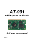
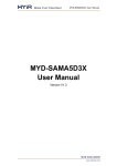
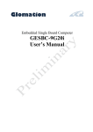
The Linux SW can be located in the NAND flash or alternatively in an SD card. If located in the
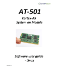
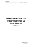
NAND flash it will be located as described in figure 1. If an SD card is used, it should be divided
to two partitions. A FAT partition for Boot, U-boot, Kernel and device tree and an additional
ext2/3/4 partition for Linux file-system see figure 2.
4 | AT-501 SW user manual 1.2
Note: When the AT-501 is equipped with both a NAND flash and valid SD card, the processor
will use the SD card.
Figure 1 – NAND Flash memory mapping
Figure 2 – SD card structure
2.2 Supported Linux version
The version delivered by Shiratech is based on the following
Linux Kernel Version 3.6.9
5 | AT-501 SW user manual 1.2
Linux Filesystem Type DEBIAN Ver 6.0.4
2.3 SW Installation steps
The following steps describes the how to install boot, U-boot, Linux Kernel, device tree and Debian file
system in to the NAND Flash. The boot and U-boot will be supplied with the SoM but the following
process can be done in case of memory corruption, or in case of an upgrade. For these cases we offer to
use the SAM-BA tools supplied by Atmel (see paragraph 4.1).
Kernel device tree and Debian file system can be installed in one of two possible ways:
Via the SAM-BA tool
Via TFTP from a host PC.
The following paragraphs will describe both options.
In case of using an SD card, the boot, U-boot and Linux Kernel and device tree files should be copied to
the FAT (16 or 32) part of the SD while the file system should be placed in the ext2 part (see figure 2).
2.3.1 SAM-BA Introduction
ATMEL provides a software tool called SAM-BA to burn the boot loader in Flash memory along with
other initialization services. To start the SAM-BA you should download the Software from ATMEL
website, from the following link:
http://www.atmel.com/tools/ATMELSAM-BAIN-SYSTEMPROGRAMMER.aspx
Note: the version should be SAM-BA 2.12 Patch 2a or higher for proper operation.
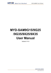
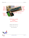
Connecting the SAM-BA
Connect the USB cable to the Micro USB (USB A) port of the board (See port location in the picture
below). Additionally by connecting the Debug port, debug massages of the SAM-BA can be viewed using
a hyper terminal application.
6 | AT-501 SW user manual 1.2
Figure 3 – Micro USB port for SAM-BA
Disabling the NAND
If the NAND flash contains a valid BOOT, it should be disabled during power up in order to enable the
operation of the SAM-BA. Disabling the NAND is done pressing the NAND disable button during power
up. Once the system is up the SAM-BA can be activated. If you are using an SD card it should be plugged
out.
Figure – 4 NAND disable push button
Double click on SAM-BA and it will open the following window:
Figure 5 - SAM-BA connecting screen
7 | AT-501 SW user manual 1.2
The virtual COM port number (COM2) may vary from PC to PC. Click Connect button and it will open a
window.
2.3.2 Bootstrap and U-boot installation steps
The following paragraph describes the download procedure for the following components:
Boot
U-boot
2.3.2.1
Boot file download procedure:
1. Choose the NandFlash media tab in the SAM-BA GUI.
2. Initialize the media choosing the Enable NandFlash action in the Scripts rolling menu and press
Execute (If the Flash is not empty it is recommended to use the Erase all option to clean the
Flash).
3. Select Send Boot File in the Scripts rolling menu and press Execute. Then select the boot file
and press Open, the media is written down.
2.3.2.2
U-boot file download procedure:
To download the U-boot to the NAND flash the following steps should be done:
1. Choose the NandFlash media tab in the SAM-BA GUI.
2. Initialize the media choosing the Enable NandFlash action in the Scripts rolling menu and press
Execute.
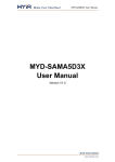
3. Select Enable OS PMECC parameters in the Scripts rolling menu and press Execute. The default
ECC Configuration should be ok(note: in patch 5 the default configuration has change, the PMECC
should be configured according to the window below) so you should have this pop-up appearing:
Figure 6 - SAM-BA ECC configuration screen
8 | AT-501 SW user manual 1.2
Select the right configuration and press the OK button.
4. To erase only the U-Boot part into the NAND FLASH, type this command after the SAM-BA
prompt:
NANDFLASH::EraseBlocks 0x40000 0xBFFFF
Then press the Enter Key.
Note: The SAM-BA EraseBlocks command take two parameters: a start and an end address of
FLASH that you want to erase.
5. Press Send File Name Browse button and choose your U-Boot binary file.
6. Enter the proper address on media in the Address text field. Its value should be 0x40000.
7. Press Send File button.
Close SAM-BA, remove the USB cable and restart the device. Once the boot and U-boot files are
installed power up the board. You will get the Boot loader prompt ( U-boot> ).
See also the picture below for the exact steps required
Figure 7 – U-boot download procedure
9 | AT-501 SW user manual 1.2
2.3.3 Linux Kernel, device tree and File system installation
The Linux Kernel, device tree and File system can be downloaded either via the SAM-BA or alternatively
using TFTP over the Ethernet port. The TFTP configuration is done using the U-boot menu.
2.3.3.1
Installation via TFTP
Once the boot loader is installed on board, the Linux kernel, device tree and file system can be installed
by the u-boot prompt using TFTP commands.
To install the SW files via TFTP do the following steps:
Open HyperTerminal on the PC. Connect a USB cable to the debug port (Mirco USB port with
build in RS232 to USB converter).
Power up the board.
Open hyper terminal application; select the virtual com detected by the PC.
o
Set the rate to 115,200 Bps, data – 8 bits, party – none, stop – 1bit and flow control –
none.
Enable a TFTP server the host PC.
Connect the Ethernet port of the board to the network
Figure 8 – Connections for TFTP
Configure the IP address of host, IP address of board and Ethernet address of board by using
10 | AT-501 SW user manual 1.2
u-boot commands as follows (The IP addresses can varied according to the setup used)
u-boot > setenv serverip 10.10.10.10
“ 10.10.10.10” is IP address of host PC.
u-boot>setenv ipaddr 10.10.10.5
“10.10.10.5” will be IP address of board.
u-boot>setenv ethaddr 12:34:56:78:9a:bc
12:34:56:78:9a:bc will be the MAC address used.
u-boot>saveenv
Save the parameters in the Flash.
In order to check the configuration you can use the printenv command.
A reset should be before starting the TFTP process.
Note: that once the MAC address is set it cannot be overwrite through the u-boot menu.
Kernel and device tree Installation
Put the file “uImage” (Kernel) and the “sama5d34ek.dtb” (device tree) on host PC on which TFTP
is configured. Disable firewall in host pc.
Run the following commands from u-boot prompt
For the device tree file:
u-boot> tftp 0x21000000 sama5d34ek.dtb
u-boot> nand erase 0x180000 0x1FFFFF
u-boot> nand write 0x21000000 0x180000 0x50E1 (size of the file – this value can be
taken for the results of the TFTP action)
For the Kernel file uImage:
u-boot> tftp 0x22000000 uImage
u-boot> nand erase 0x200000 0x600000
u-boot> nand write 0x22000000 0x200000 0x250000 (size of the file – this value can be
taken for the results of the TFTP action)
Configure the booting arguments.
u-boot> setenv bootcmd 'nand read 0x21000000 0x180000 0x50E1; nand read
0x22000000 0x200000 0x26A1A8; bootm 0x22000000 - 0x21000000'
Note: In the Shiratech U-boot version this parameter is already defined
u-boot>saveenv
11 | AT-501 SW user manual 1.2
Boot the Linux kernel using following command.
u-boot> boot
After boot it will show error proper file system couldn’t be mounted, since the file system was not
installed.
DEBIAN FILE SYSTEM Installation
To install the Debian file system follow the following steps:
Put the compressed file system image “rootfs.ubi” in tftpboot folder of host PC (the file name
should be the valid file used). The following steps are used to install Debian file system from boot
loader prompt.
u-boot> tftp 0x22000000 rootfs.ubi
u-boot> nand erase 0x800000 0xf800000
u-boot> nand write.trimffs 0x22000000 0x800000 0x3860000 (size of the file – can be
view in the results of the TFTP download, give the file size in bytes)
Reboot the board. After reboot you will get a Linux login prompt.
2.3.3.2
Installation via SAM-BA
For downloading the Kernel, device tree and file system via the SAM-BA follow the steps detailed in 2.2.1
for connecting the SAM-BA then:
1. Choose the NandFlash media tab in the SAM-BA GUI.
2. Initialize the media choosing the Enable NandFlash action in the Scripts rolling menu and press
Execute.
3. Select Enable OS PMECC parameters in the Scripts rolling menu and press Execute. The default
ECC configuration should be ok(note in patch 5 the default has change the configuration should
be as viewed in 2.3.2.2). Then press the OK button.
To download the Kernel image:
1. To erase only the kernel image into the NAND flash, type this command after the SAM-BA
prompt:
NANDFLASH::EraseBlocks 0x200000 0x600000
2. Enter the proper address on media in the Address text field. The value for the kernel image is
0x200000.
3. Press Send File Name browse button and choose your kernel image.
4. Press Send File button.
12 | AT-501 SW user manual 1.2
For download the device tree file:
1. To erase only the device tree into the NAND flash, type this command after the SAM-BA
prompt:
NANDFLASH::EraseBlocks 0x180000 0x1FFFFF
2. Enter the proper address in the Address text field. The value for the device tree is 0x180000.
3. Press Send File Name browse button and choose your device tree binary file.
4. Press Send File button.
For download the file system:
1. To erase only the NAND flash rootfs partition, type this command after the SAM-BA prompt:
NANDFLASH::EraseBlocks 0x800000 0xFFFFFFF
2. Press Send File Name browse button and choose your UBI file system.
3. Enter the proper address on media in the Address text field. The value for the file system is
0x800000.
4. Press Send File button. Wait for the end of the flashing process.
5. Close SAM-BA, remove the USB cable.
6. Restart the system and set through the U-boot menu the boot arguments according to the
following paragraph if needed.
2.3.3.3
Boot command and arguments for NAND
Boot Command for NAND:
setenv bootcmd 'nand read 0x21000000 0x180000 0x50E1; nand read 0x22000000 0x200000
0x283D70; bootm 0x22000000 - 0x21000000'
Boot argument for jffs2:
setenv bootargs = "console=ttyS0,115200 mtdparts=atmel_nand:8M(bootstrap/uboot/kernel)ro,(rootfs) root=/dev/mtdblock1 rw rootfstype=jffs2 :rootfs"
Boot argument for ubi:
setenv bootargs = "console=ttyS0,115200 mtdparts=atmel_nand:8M(bootstrap/uboot/kernel)ro,(rootfs) rw rootfstype=ubifs ubi.mtd=1 root=ubi0:rootfs
13 | AT-501 SW user manual 1.2
2.3.4 Using SD CARD
The SD card slot is located on the bottom of the CB-20.The slot is for Micro SD format only.
Figure 9 – SD card slot
The SD card should be divided to two partitions one relatively small for the boot, u-boot, device tree and
kernel, should be in FAT 16 or 32 format. For proper operation the file names should be boot, u-boot,
uImage and dtb.
The other partition will be ext2 and will be used for the file system.
The following link provides details on how to create two partitions on the SD:
http://www.at91.com/linux4sam/bin/view/Linux4SAM/SDCardBootNotice.
14 | AT-501 SW user manual 1.2
3
SW version creation and modification
The following section describe how to compile the various SW parts, how to modify the file system and
how to add user applications.
The following process was done on a PC with Ubuntu 10.04 and 12.04.
3.1 Cross Compilation
The following paragraphs describes how build the environment for cross compiling along with instruction
on how to cross compile each part of the SW
3.1.1 Introduction
The Linux platform includes several parts Bootstrap, boot loader(u-boot) Kernel and file system. The
AT91Bootstrap does some minimal initialization of SDRAM and clock. Then it will check the presence of
boot loader (u-boot). The Boot loader will initialize UART (serial) and Ethernet. Then u-boot will check
the presence of Linux kernel image. If it is present u-boot will load it from flash to DDR and starts
execution. If Linux kernel image is not present, u-boot prompt will be shown e.g: u-boot>
along with an error massage that the kernel is not found.
The U-boot provides a rich set of commands to get hardware information, downloading images to
memory, writing images to flash etc.
The Linux kernel will start execution and it will load all device drivers. Then Linux kernel will search for a
root file system in compressed format on flash. The file system provided here is based on Debian.
3.1.2 Setting Cross Compilation Environment
The following steps will lead you how to set a cross compilation environment:
Download the ARM tool chain” gcc-linaro-arm-linux-gnueabihf-2012.07-20120720_linux.tar.bz2 “ to
current directory from the following link:
https://launchpad.net/linaro-toolchain-binaries/+milestone/2012.07
Perform the following steps:
mkdir /usr/local/arm
cp gcc-linaro-arm-linux-gnueabihf-2012.07-20120720_linux.tar.bz2 /usr/local/arm/
cd /usr/local/arm
tar -jxf gcc-linaro-arm-linux-gnueabihf-2012.07-20120720_linux.tar.bz2
Set the following variables in your shell environment:
“ export PATH=/usr/local/arm/gcc-linaro-arm-linux-gnueabihf-2012.07-20120720_linux/bin:${PATH} ”
15 | AT-501 SW user manual 1.2
“ export CROSS_COMPILE=arm-linux-gnueabihf- “
“ export ARCH=arm ”
Now the cross compilation environment is ready.
3.1.3 Cross Compiling Bootstrap
The following steps will lead you how to cross compilation a Bootstarp:
Set the cross compilation environment as per the steps in section 3.1.2.
Download the bootstrap source code.
tar -xvzf AT91Bootstrap-v3.4.4.tgz
Before building Bootstrap, you have to configure it for 5series boards and to indicate where you want to
store the environment. The bootstrap can be built to be used in an internal NAND or in an SD.
cd AT91Bootstrap-v3.4.4
For NAND FLASH
“ make CROSS_COMPILE=/usr/local/arm/gcc-linaro-arm-linux-gnueabihf-2012.0720120720_linux/bin/arm-linux-gnueabihf- at91sama5d3xeknf_uboot_defconfig “
For SD Card
“ make CROSS_COMPILE=/usr/local/arm/gcc-linaro-arm-linux-gnueabihf-2012.0720120720_linux/bin/arm-linux-gnueabihf- at91sama5d3xeksd_uboot_defconfig “
Then a configure file will be generated. You can customize AT91Bootstrap with
“ make CROSS_COMPILE=/usr/local/arm/gcc-linaro-arm-linux-gnueabihf-2012.0720120720_linux/bin/arm-linux-gnueabihf- menuconfig “
“ make CROSS_COMPILE=/usr/local/arm/gcc-linaro-arm-linux-gnueabihf-2012.0720120720_linux/bin/arm-linux-gnueabihf- “
The result of this operation is a new AT91Bootstrap binary located in the binaries directory and called
at91sama5d3xek-xxxboot-uboot-3.4.bin.
at91sama5d3xek-nandflashboot-uboot-3.4.4.bin is the binary file able to boot the application
located in NAND FLASH.
at91sama5d3xek-sdcardboot-uboot-3.4.4.bin is the binary file able to boot the application
called u-boot.bin located in the FAT formatted SD card.
For proper operation the file should be renamed to boot.bin and should be located in the fat part of
the SD.
16 | AT-501 SW user manual 1.2
3.1.4 Cross Compiling U-boot
The following steps will lead you how to cross compilation a U-boot:
Set the arm cross compilation environment as per the steps in section 3.1.2. Download the u-boot
source. Extract the source with:
tar -xvjf u-boot-v2012.10-sama5d3_M5.tgz
cd u-boot-v2012.10-sama5d3_M5
Before building U-Boot, you have to configure it for 5series boards and to indicate where you want to
store the environment.
For NAND flash
“ make CROSS_COMPILE=/usr/local/arm/gcc-linaro-arm-linux-gnueabihf-2012.0720120720_linux/bin/arm-linux-gnueabihf- at91sama5ek_nandflash_config “
For SD card
“ make CROSS_COMPILE=/usr/local/arm/gcc-linaro-arm-linux-gnueabihf-2012.0720120720_linux/bin/arm-linux-gnueabihf- at91sama5ek_sdcard_config “
“ make CROSS_COMPILE=/usr/local/arm/gcc-linaro-arm-linux-gnueabihf-2012.0720120720_linux/bin/arm-linux-gnueabihf- “
The result of this operation is a u-boot binary called u-boot.bin
3.1.5 Cross Compiling Linux Kernel 3.6.9
The following steps will lead you how to cross compilation a Linux Kernel:
Set the arm cross compilation environment as per the steps in section 3.1.2.
Download the Linux kernel source.Extract the source with
tar -xvjf linux-3.6.9.tar.bz2
cd linux-3.6.9
Firstly, use the default kernel configuration
“ make ARCH=arm CROSS_COMPILE=/usr/local/arm/gcc-linaro-arm-linux-gnueabihf-2012.0720120720_linux/bin/arm-linux-gnueabihf- sama5d3_defconfig “
Then you can customize the kernel configuration with the following step:
“ make ARCH=arm CROSS_COMPILE=/usr/local/arm/gcc-linaro-arm-linux-gnueabihf-2012.0720120720_linux/bin/arm-linux-gnueabihf- menuconfig “
17 | AT-501 SW user manual 1.2
A pop up menu will enable to make changes, to modify the Kernel to support ext3, ext4 perform the
following:
For enabling ext3 and ext4 File System support in kernel you need to enable support for large (2TB+)
block devices and files that coming under the menu option Enable the block layer.
[*] Enable the block layer --->
[*] Support for large (2TB+) block devices and files
You need to enable Ext3 journalling file system support & The Extended 4 (ext4) filesystem that coming
under the menu option File systems
File systems --->
<*> Ext3 journalling file system support
<*> The Extended 4 (ext4) filesystem
Select other required features if any needed.
Save and Exit from the pop-up window of ” menuconfig ”
Build the kernel image with the following command:
“ make ARCH=arm CROSS_COMPILE=/usr/local/arm/gcc-linaro-arm-linux-gnueabihf-2012.0720120720_linux/bin/arm-linux-gnueabihf- uImage “
Build the device tree binary file according to your board. For instance for sama5d34ek:
“ make ARCH=arm CROSS_COMPILE=/usr/local/arm/gcc-linaro-arm-linux-gnueabihf-2012.0720120720_linux/bin/arm-linux-gnueabihf- sama5d34ek.dtb “
The result of these operations is a fresh kernel image and a device tree binary files in arch/arm/boot/
directory called respectively uImage and sama5d34ek.dtb.
Note: For SD card the device tree should be rename to dtb.
18 | AT-501 SW user manual 1.2
3.1.6 Building Debian file-system using Multistrap
The following steps will lead you how to cross compilation a Debian file-system:
Run apt-get update
Install Qemu for arm (“sudo apt-get install qemu-user-static”)
Install multistrap(“sudo apt-get install multistrap”)
Create a multistrap configuration file as follows:
multistrap.conf
[General]
arch=armel
directory=multistrap/
unpack=true
noauth=true
debootstrap=Grip Networking Debian
aptsources=Debian
[Grip]
packages=nano
source=http://www.emdebian.org/grip
keyring=emdebian-archive-keyring
suite=squeeze
[Debian]
packages=
source=http://ftp.debian.org/debian
keyring=debian-archive-keyring
suite=squeeze
[Networking]
packages=net-tools dhcp3-client ethtool
source=http://www.emdebian.org/grip
keyring=emdebian-archive-keyring
suite=squeeze
19 | AT-501 SW user manual 1.2
Perform the following commands:
multistrap -f path_to_multistrap.conf
cp /usr/bin/qemu-arm-static multistrap/usr/bin/
chroot multistrap/
dpkg –configure -a
Create a “multistrap/etc/hostname” file and just add “debian” as its content, then save and close that
file.
Create/edit “multistrap/etc/passwd” file and change/ paste the content as follows:
/etc/passwd
root::0:0:root:/root:/bin/bash
daemon:x:1:1:daemon:/usr/sbin:/bin/sh
bin:x:2:2:bin:/bin:/bin/sh
sys:x:3:3:sys:/dev:/bin/sh
sync:x:4:65534:sync:/bin:/bin/sync
games:x:5:60:games:/usr/games:/bin/sh
man:x:6:12:man:/var/cache/man:/bin/sh
lp:x:7:7:lp:/var/spool/lpd:/bin/sh
mail:x:8:8:mail:/var/mail:/bin/sh
news:x:9:9:news:/var/spool/news:/bin/sh
uucp:x:10:10:uucp:/var/spool/uucp:/bin/sh
proxy:x:13:13:proxy:/bin:/bin/sh
www-data:x:33:33:www-data:/var/www:/bin/sh
backup:x:34:34:backup:/var/backups:/bin/sh
list:x:38:38:Mailing List Manager:/var/list:/bin/sh
irc:x:39:39:ircd:/var/run/ircd:/bin/sh
gnats:x:41:41:Gnats Bug-Reporting System (admin):/var/lib/gnats:/bin/sh
nobody:x:65534:65534:nobody:/nonexistent:/bin/sh
libuuid:x:100:101::/var/lib/libuuid:/bin/sh
telnetd:x:101:102::/nonexistent:/bin/false
Create/edit “multistrap/etc/inittab” and change/paste the content as follows:
/etc/inittab
# /etc/inittab: init(8) configuration.
# $Id: inittab,v 1.91 2002/01/25 13:35:21 miquels Exp $
# The default runlevel.
20 | AT-501 SW user manual 1.2
id:2:initdefault:
# Boot-time system configuration/initialization script.
# This is run first except when booting in emergency (-b) mode.
si::sysinit:/etc/init.d/rcS
# What to do in single-user mode.
~~:S:wait:/sbin/sulogin
# /etc/init.d executes the S and K scripts upon change
# of runlevel.
#
# Runlevel 0 is halt.
# Runlevel 1 is single-user.
# Runlevels 2-5 are multi-user.
# Runlevel 6 is reboot.
l0:0:wait:/etc/init.d/rc 0
l1:1:wait:/etc/init.d/rc 1
l2:2:wait:/etc/init.d/rc 2
l3:3:wait:/etc/init.d/rc 3
l4:4:wait:/etc/init.d/rc 4
l5:5:wait:/etc/init.d/rc 5
l6:6:wait:/etc/init.d/rc 6
# Normally not reached, but fallthrough in case of emergency.
z6:6:respawn:/sbin/sulogin
# What to do when CTRL-ALT-DEL is pressed.
ca:12345:ctrlaltdel:/sbin/shutdown -t1 -a -r now
# Action on special keypress (ALT-UpArrow).
#kb::kbrequest:/bin/echo “Keyboard Request–edit /etc/inittab to let this
work.”
# What to do when the power fails/returns.
pf::powerwait:/etc/init.d/powerfail start
pn::powerfailnow:/etc/init.d/powerfail now
po::powerokwait:/etc/init.d/powerfail stop
# /sbin/getty invocations for the runlevels.
#
# The “id” field MUST be the same as the last
# characters of the device (after “tty”).
#
21 | AT-501 SW user manual 1.2
# Format:
# <id>:<runlevels>:<action>:<process>
#
# Note that on most Debian systems tty7 is used by the X Window System,
# so if you want to add more getty’s go ahead but skip tty7 if you run X.
#
1:2345:respawn:/sbin/getty 38400 tty1
2:23:respawn:/sbin/getty 38400 tty2
3:23:respawn:/sbin/getty 38400 tty3
4:23:respawn:/sbin/getty 38400 tty4
5:23:respawn:/sbin/getty 38400 tty5
6:23:respawn:/sbin/getty 38400 tty6
# Example how to put a getty on a serial line (for a terminal)
#
T0:23:respawn:/sbin/getty -L ttyS0 115200 vt100
#T1:23:respawn:/sbin/getty -L ttyS1 9600 vt100
# Example how to put a getty on a modem line.
#
#T3:23:respawn:/sbin/mgetty -x0 -s 57600 ttyS3
After booting, it will be a Read-only File system. To make it read/write either of the following should be
done.
Run “mount -o remount,rw /” to make it usable.
Edit multistrap/etc/fstab and paste the following into it.
/etc/fstab
proc /proc proc defaults 0 0
/dev/mmcblk0p2 /
auto errors=remount-ro 0 1
/dev/mmcblk0p1 /boot/uboot auto defaults
22 | AT-501 SW user manual 1.2
0 0
3.1.7 File-system tuning steps (only for booting from NAND FLASH)
The following steps shows how to trim and tune the file system
apt-get install openjdk-6-jre
apt-get install sqlite3
apt-get install busybox
apt-get install openssl
apt-get clean
aptitude remove apt
rm –rf /var/lib/apt/
rm –rf /var/lib/aptitude/
rm –rf /var/cache/apt/
rm –rf /usr/share/
3.1.8 Modifying Post login message
Information to be printed just after login is found in /etc/motd.
The file /var/run/motd is a text file which contains a message or system identification to be printed
before the login prompt
Distributor ID : Debian
Description : Debian GNU/Linux 6.0.4 (squeeze)
Release
Codename
: 6.0.4
: squeeze
kernel Version : 2.6.39
23 | AT-501 SW user manual 1.2
3.1.9 Modifying pre-login message
Information to be printed before login /etc/issue
Debian GNU/Linux 6.0 \n \l
____
| ||
____
|
|____| |___ |
| ||
|
| ||
|_____
EMDEBIAN CONTROLLER
The file /etc/issue is a text file which contains a message or system identification to be printed before
the login prompt. It may contain various @char and \char sequences, if supported by getty
/etc/issue - escape code
The issue-file (/etc/issue or the file set with the -f option) may contain certain escape codes to
display the system name, date and time etc. All escape codes consist of a backslash (\)
immediately followed by one of the letters explained below.
\b : Insert the baud rate of the current line.
\d : Insert the current date.
\s : Insert the system name, the name of the operating system.
\l : Insert the name of the current tty line.
\m : Insert the architecture identifier of the machine, eg. i486
\n : Insert the node name of the machine, also known as the hostname.
\o : Insert the domain name of the machine.
\r : Insert the release number of the OS, eg. 1.1.9.
24 | AT-501 SW user manual 1.2
\t : Insert the current time.
\u : Insert the number of current users logged in.
\U : Insert the string "1 user" or " users" where is the number of current users logged in.
\v : Insert the version of the OS, eg. the build-date etc
3.1.10 Creating users and passwords
Enable user guest
The following command enabled a user guest:
useradd -m -r -s /bin/bash guest
- The flag -m is used to create the guest user’s home directory if it is not existing.
- The flag -r is used to create a system account. That is, a user with a UID lower than the value of
UID_MIN defined in /etc/login.defs and whose password does not expire.
- The flag -s is used to specify the name of the user's login shell. The default is to leave this field blank,
which causes the system to select the default login shell.
Note that useradd will not create a home directory for such an user, regardless of the default setting in
/etc/login.defs. You have to specify -m option if you want a home directory for a system account to be
created.
Enable password for guest user:
The following command enabled password for user guest:
passwd guest
Then provide a password for the guest user. Verify the file /etc/passwd to see the following entry:
guest:x:999:999::/home/guest:/bin/bash
Enable password for root user:
To enable a root password use the command passwd:
passwd root
Then provide a password for the root user, verify the file /etc/passwd to see the following entry:
root:x:0:0:root:/root:/bin/bash
25 | AT-501 SW user manual 1.2
3.1.11 bashrc file – root
#configure the network
#ifconfig eth0 down
#ifconfig eth0 172.16.1.113
#ifconfig eth0 up
#route add default gw 172.16.0.1
#set the java path
export PATH=$PATH:/usr/lib/jamvm/java-1.6.0-openjdk/bin:/usr/lib/jamvm
export JAVA_HOME=usr/lib/jvm/java-1.6.0-openjdk/
#start the basic services
/usr/bin/ServiceManage
/usr/bin/dbinit
#Manage Basic service
/usr/bin/ServiceManage
3.1.12 Nandflashinfo
#!/bin/bash
df -h
26 | AT-501 SW user manual 1.2
3.1.13 Cpuinfo
#! /bin/bash
#Command will give the details of the CPU of the board
echo “Processor
: ARMv7 Processor rev 1 (v7l)”
echo “BogoMIPS
: 262.96”
echo “Features
: swp half thumb fastmult vfp edsp vfpv3 vfpv3d16 tls vfpv4 “
echo “CPU implementer : 0x41”
echo “CPU architecture: 7”
echo “CPU variant
echo “CPU part
: 0x0”
: 0xc05”
echo “CPU revision : 1”
echo “Hardware
echo “Revision
echo “Serial
: Atmel SAMA5 (Device Tree)”
: 0000”
: 0000000000000000”
3.1.14 Boardinfo
#! /bin/bash
#Command for displaying the information of the board
echo "Chipset
: AT91SAMA5D3x"
echo "Serial Interfaces : SPI , I2c"
echo "Other Interfaces : ETH , USB , UART, CAN, LCD, AUDIO"
echo "RAM size
: 256 MB"
echo "Flash Size
: 256 MB"
echo "DataFlash
: Yes"
echo "NandFlash
: Yes"
27 | AT-501 SW user manual 1.2
echo "FlashBooting
: Yes"
echo "SDCard Booting : Yes"
3.2 Running User Applications on ShiraTech Board
The following paragraph explains how a user can compile a C or JAVA coded application.
3.2.1 Cross compiling C code
Follow the below mentioned steps to cross compile C source code application:
Follow the steps mentioned in section 3.1.1 (Setting Cross Compilation Environment) to install the
toolchain before compiling the application.
Create a sample C program. For e.g. source.c
Compile the program using:
“arm-linux-gcc source.c -o source_output -static”
Then the result will be a binary named “source_output”.
Transfer the binary using one of the following options:
Using scp, transfer the source_output binary to the file-system:
“scp –r source_output root@<shiratech_board_IPaddress>:/root/”
Using tftp, transfer the source_output binary to the file-system using,
“tftp -g -r source_output tftp_server_ip”
Give execution permission to “source_output” using:
“chmod +x source_output”
Run the binary using:
“./source_output
3.2.2 Cross compiling Java code
Follow the below mentioned steps to cross compile Java source code application
For compiling java applications, we need java jdk version 1.6.0_24 in Ubuntu Linux machine
Install java jdk version 1.6.0_24, using below command.
“sudo apt-get install openjdk-6-jdk”
Use “java –version” command to get the current jdk version.
Compile the java application using
28 | AT-501 SW user manual 1.2
“javac Source_name.java”
The result of the above command will get like
“Source_name.class”
There are two options to transfer the application
Using “scp –r source_output root@<shiratech_board_IPaddress>:/root/”
Using “tftp –g –r Source_name.class tftp_server_ip”
Run java application using,
“java Source_name”
29 | AT-501 SW user manual 1.2
4
CB-20 Carrier board description
4.1 Overview
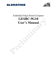
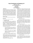
The CB-20 is a fully featured development and carrier board for ShiraTech’s AT-501 system on modules.
The board is used by software developer as a development platform with all relevant peripherals for
simulating the target product functionalities. It can also be used as a reference design for hardware
teams or as a ready for use control and display unit to be integrated in commercial products.
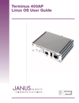
Figure 1 – CB-20 interfaces
Notes:
1. The debug port includes a build in RS-232 to USB converter. It can be connected to the PC using the
Micro USB to USB cable supplied with the evaluation board. The board can be controlled using a hyper
terminal application over USB. The port should be configured to the following parameters:
Rate to 115,200 Bps, data – 8 bits, party – none, stop – 1bit and flow control – none.
2. The USB OTG port can be used for SAM-BA connectivity.
3. The JTAG interface can be used for connecting the AT91SAM-ICE. The jumper, JP-1, select between
JTAG testing ("0") and ICE or normal operation.
For both normal operation and ICE it should be left open.
30 | AT-501 SW user manual 1.2
4.2 CB20 interfaces mapping
The CB-20 offers a large variety of interfaces for supporting a large variety of applications. The following
table provides mapping between the various interfaces and the internal ports of the CPU.
Note: On the PS (there is a label for each connector)
Interface
Connector name
Processor interface
Remarks
Debug port
J-14
PB-30,PB31
Micro USB Type A/B. An
internal RS232 to USB
converter by FTDI.
USB OTG
J-11
HHSDMA, HHSDPA
USB 2.0 Type-A Host/Device
USB host port 1
J-10
HHSDMB, HHSDPB
USB 2.0 Type-A Host
USB host port 2
J-9
HHSDMC, HHSDPC
USB 2.0 Type-A Host
Interface from USB HUB
HDMI
J-8
LCD Interface
19 pins Type-A Receptacle
Audio interface 1
J-3
Audio Interface
Stereo Out
Audio interface 2
J-2
Audio Interface
Stereo Line in
Giga Ethernet port
J-24
Ethernetg Port 0
Rj-45
RS232 port
J-1
USART 1
DB-9
CAN interface 0
J-23
CAN0
RJ-11
CAN interface 1
J-22
CAN1
RJ-11
JTAG interface
J-16
Extender
J-18
Power inlet
J-17
20 pins 2.54 Header
SPI-1, USART-3, I2C from
Extender, 10 GPI
30 pins 1.25 Header
Power Jack, 5-9 Volt
Table 1 – External interfaces mapping
31 | AT-501 SW user manual 1.2
Notes:
USB support:
Port-C supports USB 2.0 Host is connected via a USB-HUB device to the external interface.
The control and monitor of the USB is done using GPIOs listed in 4.3.
4.3 Interrupt & I/O Table
The following table describes the AT-501 I/O configuration used by the SW. To keep compatibility with
the AT-501 SW these I/O must be used for the following interfaces:
Signal
I/O
Description
Remarks
E0 INTR
PB-25
Giga Ethernet 0 interrupt
Active Low
E1 INTR
PE-30
Fast Ethernet 1 interrupt
Active Low
MCI0 CD
PD-17
uSD card detect
0 – Card in
1 – No card
MCI1 CD
PD-18
SD card detect
0 – Card in
1 – No card
VBUS Sense
PD-29
USB port A power sense
0 – No power sensed
1 – Power sensed
OverCur USB
PD-28
USB port A or Port B over current
Open Drain
EN5V HDA#
PD-25
USB port A power drive enable
0 – Enable
1 – Disable (Default)
EN5V HDB#
PD-26
USB port B power drive enable
0 – Enable
1 – Disable (Default)
EN5V HDC#
PD-27
USB port C power drive enable
0 – Enable
1 – Disable (Default)
Table 2 – Configured I/O and Interrupts
32 | AT-501 SW user manual 1.2
NOTE – More interrupts can be available using the SAMA5D I/O pins can be configured according to the
user application.
NOTE – When an interface is not in use its relevant I/O can be used as a general purpose I/O.
4.4 Jumpers
The CB-20 holds several jumpers for various applications:
JP-1 JTAG enable – if open Normal operation, JTAG emulator can be connected. If closed JTAG mode is
enabled.
JP-2, JP-3 – Battery bypass - If closed normal operation, open Battery support ( note that it is enough
that one of them will be closed for normal operation).
33 | AT-501 SW user manual 1.2