1
CONTROLLER (continued)
Series 185
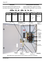
S1 DIP switch
S3 DIP switch
S2 DIP switch
Figure 6. DIP switches S1 and S2 at the top right.
The time delay settings are shown in Figures 6 and 7 and
in Table C. The sensor settings are shown in Figure 6
and in Table D. The standard (factory) settings are
shown in Tables C, D, and H.
Figure 7. DIP switch S3 at the bottom center.
Table C. Time Delay Settings
Time Delay Description
Factory Setting
override momentary
utility outages
3 seconds
transfer to generator
10 seconds (approx.)
override momentary
generator outages
4 seconds
transfer to utility
5 minutes (approx.)
unloaded running
(generator cooldown)
2 minutes
Settings
DIP Switch
DIP Actuator
Actuator Position
1 second
S2
1
on (up)
3 seconds
S2
1
off (down)
–
–
–
–
4 second
S3
9
on (up)
0
S3
9
off (down)
–
–
–
–
2 minutes
S1
10
on (up)
5 minutes
S1
10
off (down)
Table D. Voltage and Frequency Settings
Setting Description
voltage
frequency
phase
Setting
Factory Setting
Settings
DIP Switch
DIP Actuator
Actuator Position
–
220 – 240 V
non–adjustable
S2
2
on (up)
50 Hz
S1
4
on (up)
nominal
60 Hz
–
single
pickup
198 V
60 Hz
S1
4
off (down)
non–adjustable
S1
6
on (up)
198 V
S1
3
on (up)
209 V *
S1
3
off (down)
S1
1
off (down)
S1
2
off (down)
S1
1
on (up)
S1
2
off (down)
S1
1
off (down)
S1
2
on (up)
S1
1
on (up)
S1
2
on (up)
non–adjustable
–
–
–
non–adjustable
–
–
–
198 V *
utility voltage
187 V
dropout
187 V
176 V
154 V
generator voltage
generator frequency
pickup
198 V
dropout
165 V
pickup
57 Hz (nom 60 Hz)
48 Hz (nom 50 Hz)
dropout
51 Hz (nom 60 Hz)
43 Hz (nom 50 Hz)
* If the dropout voltage is set to 198 V, the pickup voltage must be set to 209 V.
381333–319 D
4