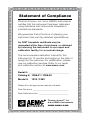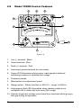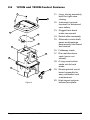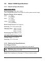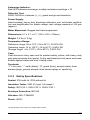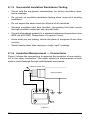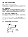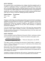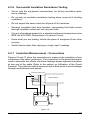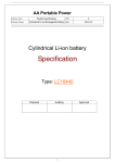
1
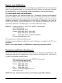
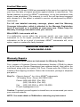
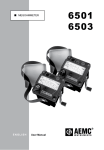
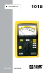
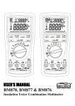
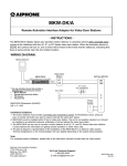
1210N 1250N MEGOHMMETER x1 0 200 500 MΩ 100 20 50 10 0 300 VC AT II /1 20 000V C AT I 2 15 200 3 600 30 ! 1.5 1kV 5 V 00V 100 50 4 0 5 4 0 40 0 50 10 EN ® M R TE ME 0N HM 25 GO l 1 ME ode M TS (250V) RU (1kV) ST User Manual 1 (500V) 600 IN ENGLISH Statement of Compliance Chauvin Arnoux®, Inc. d.b.a. AEMC® Instruments certifies that this instrument has been calibrated using standards and instruments traceable to international standards. We guarantee that at the time of shipping your instrument has met its published specifications. An NIST traceable certificate may be requested at the time of purchase, or obtained by returning the instrument to our repair and calibration facility, for a nominal charge. The recommended calibration interval for this instrument is 12 months and begins on the date of receipt by the customer. For recalibration, please use our calibration services. Refer to our repair and calibration section at www.aemc.com. Serial #: _ ________________________________ Catalog #: 1326.01 / 1326.02 Model #: 1210 / 1250 Please fill in the appropriate date as indicated: Date Received: __________________________________ Date Calibration Due: ________________________ Chauvin Arnoux®, Inc. d.b.a AEMC® Instruments www.aemc.com Table of Contents 1. INTRODUCTION....................................................................3 1.1 International Electrical Symbols......................................................3 1.2 Definition of Measurement Categories............................................4 1.3 Receiving Your Shipment................................................................4 1.4 Ordering Information.......................................................................4 1.4.1 Accessories and Replacement Parts.................................4 2. PRODUCT FEATURES...........................................................5 2.1 Description......................................................................................5 2.2 Model 1210N Features...................................................................6 2.3 Model 1250N Features...................................................................6 2.4 Model 1210N Control Features.......................................................7 2.5 Model 1250N Control Features.......................................................8 2.6 1210N and 1250N Control Features...............................................9 3. SPECIFICATIONS................................................................10 3.1 Model 1210N Specifications.........................................................10 3.1.1 Electrical Specifications....................................................10 3.1.2 Mechanical Specifications................................................ 11 3.1.3 Safety Specifications........................................................ 11 3.2 Model 1250N Specifications.........................................................12 3.2.1 Electrical Specifications....................................................12 3.2.2 Mechanical Specifications................................................12 3.2.3 Safety Specifications........................................................13 4. OPERATION........................................................................14 4.1 Using the Model 1210N................................................................14 4.1.1 Instrument Ground Terminal.............................................14 4.1.2 Auto-ranging.....................................................................14 4.1.3 Safety Check - Voltage Test ............................................14 4.1.4 Insulation Resistance Testing (MΩ Range)......................14 4.1.5 Successful Insulation Resistance Testing.........................16 4.1.6 Insulation Measurement — Connections.........................16 4.1.7 Insulation Resistance Measurements on Motors.............19 4.2 Using the Model 1250N................................................................21 4.2.1 Instrument Ground Terminal.............................................21 4.2.2 Auto-ranging.....................................................................21 4.2.3 Safety Check - Voltage Test ............................................21 4.2.4 Utilization of the Guard Terminal......................................21 4.2.5 Insulation Resistance Testing (MΩ Range)......................23 4.2.6 Successful Insulation Resistance Testing.........................25 4.2.7 Insulation Measurement - Connections............................25 4.2.8 Insulation Resistance Measurements on Motors.............28 5. MAINTENANCE...................................................................30 5.1 Warning . ......................................................................................30 5.2 Cleaning........................................................................................30 Repair and Calibration..................................................................................31 Technical and Sales Assistance...................................................................31 Limited Warranty..........................................................................................32 Warranty Repairs..........................................................................................32 2 Megohmmeter Models 1210N/1250N CHAPTER 1 INTRODUCTION Warning These safety warnings are provided to ensure the safety of personnel and proper operation of the instrument. • Read the instruction manual completely and follow all safety information before operating this instrument. • Safety is the responsibility of the operator! • Tests are to be carried out only on dead circuits! Check for live circuits before making resistance measurements (safety check). • The Megohmmeter Models 1210N/1250N are sources of high voltage, as is the sample connected to them. All persons performing or assisting in the tests must employ all safety precautions to prevent electrical shock to themselves and to others. • AEMC® Instruments considers the use of rubber gloves to be an excellent safety practice even if the equipment is properly operated and correctly grounded. • When testing capacitance samples, make sure that they have been properly discharged and that they are safe to touch. Dielectric insulation samples should be short-circuited for at least five times the amount of time they were energized. • Use the leads supplied with the megohmmeter. If defective or used, replace before testing. 1.1 International Electrical Symbols This symbol signifies that the instrument is protected by double or reinforced insulation. Use only specified replacement parts when servicing the instrument. This symbol on the instrument indicates a WARNING and that the operator must refer to the user manual for instructions before operating the instrument. In this manual, the symbol preceding instructions indicates that if the instructions are not followed, bodily injury, installation/ sample and product damage may result. Risk of electric shock. The voltage at the parts marked with this symbol may be dangerous. Megohmmeter Models 1210N/1250N 3 1.2 Definition of Measurement Categories Cat. I: For measurements on circuits not directly connected to the AC supply wall outlet such as protected secondaries, signal level, and limited energy circuits. Cat. II: For measurements performed on circuits directly connected to the electrical distribution system. Examples are measurements on household appliances or portable tools. Cat. III: For measurements performed in the building installation at the distribution level such as on hardwired equipment in fixed installation and circuit breakers. Cat. IV: For measurements performed at the primary electrical supply (<1000V) such as on primary overcurrent protection devices, ripple control units, or meters. 1.3 Receiving Your Shipment Upon receiving your shipment, make sure that the contents are consistent with the packing list. Notify your distributor of any missing items. If the equipment appears to be damaged, file a claim immediately with the carrier and notify your distributor at once, giving a detailed description of any damage. Save the damaged packing container to substantiate your claim. Do not use an instrument that appears to be damaged. 1.4 Ordering Information Megohmmeter Model 1210N.............................................. Cat. #1326.01 Megohmmeter Model 1250N.............................................. Cat. #1326.02 Both models include a carrying strap with lead pouch, three color-coded leads, ground lead, two insulated alligator clips, test probe and user manual. 1.4.1 Accessories and Replacement Parts Set of 10 fuses, 0.2A, 250V fast-blow 5x20mm................... Cat. #2973.02 Lead pouch with three color-coded safety leads, ground lead, two safety alligator clips and test probe.......... Cat. #1019.01 Lead pouch with three color-coded leads, ground lead, two alligator clips, and test probe.................... Cat. #1017.56 4 Megohmmeter Models 1210N/1250N CHAPTER 2 PRODUCT FEATURES 2.1 Description The AEMC® Models 1210N and 1250N are compact, self-contained handcranked megohmmeters. They are practical and dependable instruments designed for a broad range of plant and field service applications, such as acceptance testing and preventive maintenance of wiring, cables, switchgear, and motors. The easy hand-cranked operation provides a steady rectified DC voltage output across the entire range for consistently reliable readings. These megohmmeters incorporate a built-in, sealed alternator and a constant DC voltage circuit to provide a stable output and give direct insulation resistance reading. They are ruggedly built and use an O-ring-sealed, cast aluminum case with a polycarbonate front panel designed for harsh, heavy-duty use and protection against dust and water. The Models 1210N/1250N have a unique auto-ranging feature which expands the scale by x10 and almost doubles the scale length. When the pointer reaches near the end of scale, the auto-ranging feature activates, returning the pointer to the beginning of the scale with the x10 red LED indicator on. Insulation resistance is indicated with a rugged taut-band meter movement on a logarithmic scale. The indicator scale is easy to read. Megohmmeter Models 1210N/1250N 5 2.2 Model 1210N Features • Measures insulation at 500V, resistance, continuity • Test voltage constant across the entire measurement range • Autoranging MΩ, kΩ and Ω ranges • Designed for harsh environments: offshore, mining, heavy-duty field, industrial, and military use • Extra rugged cast aluminum case; O-ring sealed against rain, water, and dust; aluminum lid • Compact, self-contained package; folding crank • Large direct-reading scale • 600V test voltage range (safety check) 2.3 Model 1250N Features • Three test voltages: 250, 500, 1000V • Test voltage constant across the entire measurement range • Autoranging MΩ ranges • Designed for harsh environments: offshore, mining, heavy-duty field, industrial, and military use • Extra rugged cast aluminum case; O-ring sealed against rain, water, and dust; aluminum lid • Compact, self-contained package, folding crank • Four terminals including guard and ground • Large direct-reading scale • 600V test voltage range (safety check) 6 Megohmmeter Models 1210N/1250N 2.4 Model 1210N Control Features 2 1 3 FUS 4 10 600V CAT II / 1000V CAT I x 10 9 10 3 54 20 0 30 2 100 3 4 200 5 6 300 40 7 400 0.5 8 500 0 (5 50 9 1 0 600 00 V) (1m A) (5m A) 2 ! C 42 Ω M V Ω Ω V 1 5 20 10 ΜΩΩ 0 κ ! 1 2 kΩ ® 8 INSTRUMENTS MEGOHMMETER Model 1210N 6 7 Figure 1 1. Line (-) terminal Black 2. Fuse 0.2A 3. Earth (+) terminal Red 4. Instrument ground terminal for user safety 5. Amber LED illuminates when proper crank speed is attained, indicating presence of selected output 6. Foldaway handle 7. Mechanical zero adjustment screw 8. Range switch - safety test first on MΩ/V range to 500VAC 9. Autoranging: Red LED illuminates when reading needs to be multiplied x10 to obtain the true value (MΩ, kΩ, Ω ranges) 10. Security finger rest isolates users hand from terminals while giving a firm grip during an operation Megohmmeter Models 1210N/1250N 7 2.5 Model 1250N Control Features 2 1 3 G 4 10 600V CAT II / 1000V CAT I x 10 9 0 50 0 30 50 4 20 100 0 3 54 10 ΜΩ 20 50 100 200 20 2 300 ! 5 15 10 1.5 400 (1 500 0 600 ) 2 ! C 42 500V V 25 kV (2 50 00 V) V) (5 1k 0V V 1 ® V 8 INSTRUMENTS MEGOHMMETER Model 1250N 6 7 Figure 1-A 1. Line (-) terminal - Black 2. Guard terminal - Blue 3. Earth (+) terminal - Red 4. Instrument ground terminal for user safety 5. Green LED illuminates when proper crank speed is attained, indicating presence of selected test voltage 6. Foldaway handle 7. Mechanical zero adjustment screw 8. Range switch - Safety test first on 500 V/V ~ range to 500VAC 9. Autoranging: Red LED illuminates when reading needs to be multiplied x10 to obtain the true value (MΩ range) 10. Security finger rest isolates users hand from terminals while giving a firm grip during an operation 8 Megohmmeter Models 1210N/1250N 2.6 1210N and 1250N Control Features 11. Long, sturdy assembly bolts for tight case closing. 11 12 12. Instrument ground terminal for enhanced user safety. 13. Rugged taut-band meter movement. 20 13 14. Switch slide assembly. 15. Alternator crank shaft, gears and bearings permanently lubricated and sealed. 14 19 16. Foldaway crank. 17. Die cast aluminum case (cover not shown). 15 18 18. O-ring construction seals out dirt and water. 17 16 Figure 2 Megohmmeter Models 1210N/1250N 19. Simple printed circuit board assembly for easy calibration and maintenance. 20. High impact polycarbonate face plate. 9 CHAPTER 3 SPECIFICATIONS 3.1 Model 1210N Specifications 3.1.1 Electrical Specifications INSULATION TESTS DC Test Voltage: 500V (test voltage generated in full across the entire measurement range) Megohm Range (Auto-ranging): 0.5 to 5.5MΩ; 5.5 to 200MΩ Short Circuit Current: 5mA (max) Accuracy: 2.5% of full scale length Charging Time: 0.5 s/µF Discharging Time (Auto): 5 s/µF RESISTANCE TESTS DC Test Current: 1mA constant, 600V max Kilohm Range (Auto-ranging): 0 to 45kΩ; 45 to 500kΩ Accuracy: 2.5% full scale length Charging Time: 0.5 s/µF Discharging Time (Auto): 5 s/µF CONTINUITY TESTS DC Test Current: 5mA constant, 10V max Ohm Range (Auto-ranging): 0 to 9Ω; 9 to 100Ω Accuracy: 2% of full scale length Fuse Protection: 0.2A, 250V, fast-blow, 5x20mm VOLTAGE TESTS (Safety Check): Voltage Range: 0 to 600VAC Frequency: 45 to 450Hz Accuracy: 3% of full scale Input Impedance: 100kΩ (approx) 10 Megohmmeter Models 1210N/1250N 3.1.2 Mechanical Specifications Test Voltage Indicator: Amber LED indicates proper test voltage and crank speed Scale: Direct readings on all ranges; 3" (76mm), black on white Autorange Indicator: Red LED indicates Auto-range; multiply resistance readings x 10 Power Supply: Hand-cranked, heavy duty brushless alternator and solid state rectification and amplification for stable voltage; test voltage reached at 140 rpm (approx) Dielectric Test: 2000V 50/60 Hz, between (-), (+), and ground terminals Meter Movement: Rugged taut band suspension Dimensions: 4.7 x 4.7 x 5.1" (120 x 120 x 130mm) Weight: 3.3 lbs (1.5 kg) Temperature Range: Reference range: 64 to 75°F (18 to 24°C), 30-50% RH Operating range: 14 to 122°F (-10 to 50°C), 0-80% RH Storage range: -4 to 176°F (-20 to 80°C), 0-90% RH Case: Cast aluminum alloy case and lid painted safety yellow, with heavy duty gray polycarbonate front panel; O-ring seal between front panel and case; sealed against water and dust; folding crank Terminals: “+” Line (red); “-” earth (black); accepts standard 4mm safety banana plugs; ground accepts 4mm banana plug or spade lugs 3.1.3 Safety Specifications Sealed: IP54 with lid, IP52 without lid Insulation Tester: VDE 413 part 1/4 except f Safety: IEC1010-1; 600V CAT II; 1000V CAT I Envelope Protection: IEC529 Vibration: MIL-T-38800D Shock: IEC51 Megohmmeter Models 1210N/1250N 11 3.2 Model 1250N Specifications 3.2.1 Electrical Specifications INSULATION TESTS DC Test Voltages: 250, 500, 1000V (Test voltages generated in full across the entire measurement range) Megohm Ranges (Auto-ranging): 250V: 1 to 11MΩ 11 to 500MΩ 500V: 1 to 11MΩ 11 to 500MΩ 1000V: 10 to 110MΩ 110 to 5000MΩ Short Circuit Current: 5mA (approx) Accuracy: 2% of full scale length Charging Time: 250V: 0.2 s/µF 500V: 0.5 s/µF 1000V: 0.5 s/µF Discharging Time (Auto): 8 s/µF VOLTAGE TESTS (Safety Check) Voltage Range: 0 to 600VAC Accuracy: 3% of full scale 3.2.2 Mechanical Specifications Test Voltage Indicator: Green LED indicates proper test voltage and crank speed Warning: If the crank speed LED is not ON during test ing, the reading is not valid. Scale: Direct readings on all ranges; 3" (76mm), black on white 12 Megohmmeter Models 1210N/1250N Autorange Indicator: Red LED indicates autorange; multiply resistance readings x 10 Dielectric Test: 2000V 50/60 Hz, between (-), (+), guard and ground terminals Power Supply: Hand-cranked, heavy duty brushless alternator and solid state rectification and amplification for stable voltage; test voltage reached at 140 rpm (approx) Meter Movement: Rugged taut band suspension Dimensions: 4.7 x 4.7 x 5.1" (120 x 120 x 130mm) Weight: 3.3 lbs (1.5 kg) Temperature Range: Reference range: 64 to 75°F (18 to 24°C), 30-50% RH Operating range: 14 to 122°F (-10 to 50°C), 0-80% RH Storage range: -4 to 176°F (-20 to 80°C), 0-90% RH Case: Cast aluminum alloy case and lid painted safety yellow, with heavy duty gray polycarbonate front panel; O-ring seal between front panel and case; sealed against water and dust; folding crank Terminals: “+” Line (red); “-” earth (black); “G” guard (blue); accepts safety 4mm banana plugs; ground accepts 4mm banana plugs or spade lug 3.2.3 Safety Specifications Sealed: IP54 with lid, IP52 without lid Insulation Tester: VDE 413 part 1/4 except f Safety: IEC1010-1; 600V CAT II; 1000V CAT I Envelope Protection: IEC529 Vibration: MIL-T-38800D Shock: IEC51 *All specifications are subject to change without notice Megohmmeter Models 1210N/1250N 13 CHAPTER 4 OPERATION 4.1 Using the Model 1210N 4.1.1 Instrument Ground Terminal The Megohmmeter Model 1210N is equipped with an instrument ground terminal for enhanced user safety. Ground your instrument when in use. 4.1.2 Auto-ranging How it works: When the pointer reaches approximately 90% of the full scale length, the auto-range is triggered, the red auto-range (x10) LED lights up. The pointer goes back to the beginning of the scale and resumes its travel. The readings should be multiplied by 10 when the x10 LED is on. 4.1.3 Safety Check - Voltage Test Before measuring insulation resistance, confirm that the sample is fully discharged (particularly in dielectric and capacitance samples) and that the sample is not connected to an energized circuit. To perform the voltage test, set the range selection to V (MΩ), connect and read on the red voltage scale (600VAC max). DO NOT CRANK. If measuring on a DC circuit, the pointer will deflect but the measurement may be inaccurate. 4.1.4 Insulation Resistance Testing (MΩ Range) After checking for a live circuit (see Safety Check above), select the MΩ range and connect the megohmmeter. Several connection examples are illustrated further. Crank the handle until the amber LED on the upper right-hand side lights, ensuring appropriate test voltage at the output. 14 Megohmmeter Models 1210N/1250N SPOT TESTING As a general rule in spot testing, test voltage should be applied until no variation in reading is noted for 15 seconds or applied for a fixed 60 seconds. On capacitance circuits, cranking for up to a minute or more may be necessary to fully charge the sample. What minimum value should be measured? The IEEE standard N° 43-2000 states that it is impossible to specify the value of insulation resistance at which a winding will fail electrically, but on motors, minimum readings generally stated are: Rated Voltage R minimum 250 or less 2 MΩ 460 2 MΩ There is no fixed figure for determining what is good and bad in resistance readings, but a good guide would be 1 megohm for every one hundred applied operating volts, as a minimum figure. This applies to motors and transformers. When the insulation resistance gets this low, an electrical break-down can be expected at any time and rewinding or replacing should be considered. It is not unusual for a winding to be 10 to 100 times the recommended minimum value (IEEE standard 43-2000: Recommended Practice for Testing Insulation Resistance of Rotating Machinery), but this varies with temperature and humidity. RATIO TESTING In time resistance reading (Dielectric Absorption Ratio), readings are taken at 30 seconds and 60 seconds to obtain the dielectric absorption ratio. Insulation resistance @ 60s Insulation resistance @ 30s = Dielectric Absorption ratio (DAR) This test is useful to increase the accuracy of spot testing. In general, a ratio of 1.25:2 or better should be required. A ratio below this indicates that repair is probably needed. Remember that a DC insulation test may be used for acceptance testing, but is more commonly used to check the gradual deterioration of equipment over its life. Consult your equipment manufacturer for specific test or test voltage if not known. Insulation resistance decreases with moisture, temperature and age and should be recorded over time at a given temperature and corrected. Megohmmeter Models 1210N/1250N 15 4.1.5 Successful Insulation Resistance Testing • Check with the equipment manufacturer for factory insulation resistance readings. • Do not rely on insulation resistance testing alone as proof of winding conditions. • Do not expect the same value for all parts of all machines. • Observe consistent test time duration, recognizing that total current through insulation under test will vary with time. • Correct all readings properly to a standard reference temperature (see IEEE std #43-2000, Temperature Correction Curve). • Know what you are testing. Isolate the piece of equipment from other circuitry. • Watch trends rather than relying on single “spot” readings. 4.1.6 Insulation Measurement — Connections Figure 3 shows the connections to measure the insulation of one conductor to the other conductors. The cable should be disconnected at both ends to avoid leakage through switchboards and panels. Conductor Under Test Cable Insulation Fus Figure 3 16 Megohmmeter Models 1210N/1250N Figures 4 and 5 show the connections for testing insulation from a supply conductor to ground (motor frame). Conductor Under Test Cable Insulation Fus Figure 4 Conductor Under Test Cable Insulation Fus Figure 5 Figure 6 shows the connections to a transformer (lighting or distribution). Make sure that the switches and/or circuit breakers on both sides are open. Check the high voltage winding to ground, low voltage to ground, and the resistance between them with no winding ground. Megohmmeter Models 1210N/1250N 17 Tested Winding Transformer Grounding Lug Fus Figure 6 Figure 7 shows the connections for measuring the insulation of a threephase line to ground by connecting the jumpers between phases. This gives a reading of all conductors at once. If a load such as a motor, heater, etc., is attached to the other end of the line, it will read the load resistance to ground at the same time. By removing the jumpers, readings can be made between the individual conductors and ground. Jumpers ~ ~ ~ ~ ~ ~ Fus Figure 7 18 Megohmmeter Models 1210N/1250N 4.1.7 Insulation Resistance Measurements on Motors Figure 8 shows reading the resistance to ground of a three-phase motor winding. Since the three-phase motors are internally connected, it is only necessary to connect one lead to the motor lead and the other lead to the motor frame as shown. Fus Figure 8 Figure 9 shows the windings of a three-phase motor separated. Sometimes this can be done at the lead terminals, while other times the end bells must be removed to get at the lead wires of the coils. By connecting the megohmmeter as shown, the phase insulation resistance value can now be determined. Read between phases “A” and “B”, then “B” and “C”, then “C” and “A”. C A B Fus Figure 9 Megohmmeter Models 1210N/1250N 19 Figure 10 shows connections for testing insulation from a supply conductor in a switchbox to ground (motor frame). An identical test may be carried out from the motor starter. Motor Side of Switch: Connection to One Leg Starter In Grounded Motor Frame Fus Figure 10 20 Megohmmeter Models 1210N/1250N 4.2 Using the Model 1250N 4.2.1 Instrument Ground Terminal The Megohmmeter Model 1250N is equipped with an instrument ground terminal for enhanced user safety. Ground your instrument when in use. 4.2.2 Auto-ranging How it works: When the pointer reaches approximately 90% of the full scale length, the auto-range is triggered, the red auto-range (x10) LED lights up. The pointer goes back to the beginning of the scale and resumes its travel. The readings should be multiplied by 10 when the x10 LED is on. 4.2.3 Safety Check - Voltage Test Before measuring insulation resistance, confirm that the sample is fully discharged (particularly in dielectric and capacitance samples) and that the sample is not connected to an energized circuit. To perform the voltage test, set the range selection to 500V, connect and read on the red voltage scale (600VAC max). DO NOT CRANK. If measuring on a DC circuit, the pointer will deflect but the measurement may be inaccurate. 4.2.4 Utilization of the Guard Terminal E C A B E = Exposed surface A = Insulation B = Shield C = Conductor G Figure 13 Megohmmeter Models 1210N/1250N 21 Guard terminals are useful when measuring high resistance values and for stabilizing readings. When testing the insulation at the end of a cable, it is necessary to eliminate the error from surface leakage which occurs, particularly at high resistance values. The purpose of the guard terminal is to provide a third terminal within the path of the surface leakage “E”. Connect the instrument as shown in Figure 13. If there is no shield at “B”, use a copper wire wound several times around the exposed surface “B”. (Note: If a shield is not available and you do not make up a shield around “B” and connect to the guard terminal (-), the measurement will be erroneous and lead to confusion as to the cable’s state.) If the guard terminal is not connected at “B”, the instrument measures the current “I” flowing through the insulation and a surface leakage current “i1”. See Figure 14. NO CONNECTION to Guard terminal B i1 Rx: resistance through insulation Ry Rz Ry: surface resistance Rz: surface resistance Rx To EARTH A terminal C To LINE terminal I Figure 14 22 Megohmmeter Models 1210N/1250N When the guard terminal is connected at “B”, the instrument measures the current “I” and not the surface leakage current “i1”, which is not included in the measurement. See Figure 15. This type of measurement will give the true value of the resistance “Rx”, providing the “Ry” and “Rz” are not too low. To Guard terminal B i1 Rx: resistance through insulation Ry Rz Ry: surface resistance Rz: surface resistance Rx To EARTH A terminal C To LINE terminal I Figure 15 4.2.5 Insulation Resistance Testing (MΩ Range) After checking for a live circuit (see safety check), select the test voltage and connect the megohmmeter. Several connection examples are illustrated further. Crank the handle until the green LED on the upper right-hand side lights, ensuring that the selected test voltage has been reached. TEST VOLTAGE No published standard tells which voltage to choose for any given winding. However, published recommendations could be summarized as follows: Rated Voltage of Motor Below 115 115 230 460 Megohmmeter Models 1210N/1250N Test Voltage 250V 250 or 500V 500V 500 or 1000V 23 SPOT TESTING As a general rule in spot testing, test voltage should be applied until no variation in reading is noted for 15 seconds or applied for a fixed 60 seconds. On capacitance circuits, cranking for up to a minute or more may be necessary to fully charge the sample. What minimum value should be measured? The IEEE standard N° 43-2000 states that it is impossible to specify the value of insulation resistance at which a winding will fail electrically, but on motors, minimum readings generally stated are: Rated Voltage R minimum 250 or less 2 MΩ 460 2 MΩ There is no fixed figure for determining what is good and bad in resistance readings, but a good guide would be 1 megohm for every one hundred applied operating volts, as a minimum figure. This applies to motors and transformers. When the insulation resistance gets this low, an electrical break-down can be expected at any time and rewinding or replacing should be considered. It is not unusual for a winding to be 10 to 100 times the recommended minimum value (IEEE standard 43-2000: Recommended Practice for Testing Insulation Resistance of Rotating Machinery), but this varies with temperature and humidity. RATIO TESTING In time resistance reading (Dielectric Absorption Ratio), readings are taken at 30 seconds and 60 seconds to obtain the dielectric absorption ratio. Insulation resistance @ 60s Insulation resistance @ 30s = Dielectric Absorption ratio (DAR) This test is useful to increase the accuracy of spot testing. In general, a ratio of 1.25:2 or better should be required. A ratio below this indicates that repair is probably needed. Remember that a DC insulation test may be used for acceptance testing, but is more commonly used to check the gradual deterioration of equipment over its life. Consult your equipment manufacturer for specific test or test voltage if not known. Insulation resistance decreases with moisture, temperature and age and should be recorded over time at a given temperature and corrected. 24 Megohmmeter Models 1210N/1250N 4.2.6 Successful Insulation Resistance Testing • Check with the equipment manufacturer for factory insulation resistance readings. • Do not rely on insulation resistance testing alone as proof of winding conditions. • Do not expect the same value for all parts of all machines. • Observe consistent test time duration, recognizing that total current through insulation under test will vary with time. • Correct all readings properly to a standard reference temperature (see IEEE std #43-2000, Temperature Correction Curve). • Know what you are testing. Isolate the piece of equipment from other circuitry. • Watch trends rather than relying on single “spot” readings. 4.2.7 Insulation Measurement - Connections Figures 16 and 17 show the connections to measure the insulation of one conductor to the other conductors. The connection to the guard terminal is used to eliminate the effects of surface leakage across exposed insulation at one end of the cable. Refer to the section on Utilization of the Guard Terminal. The cable should be disconnected at both ends to avoid leakage through switchboards and panels. Conductor Under Test Cable Insulation G Figure 16 Megohmmeter Models 1210N/1250N 25 Conductor Under Test Cable Insulation G Figure 17 Figure 18 shows the connections to a transformer (lighting or distribution). Make sure that the switches and/or circuit breakers on both sides are open. Check the high voltage winding to ground, low voltage to ground, and the resistance between them with no winding ground. Tested Winding Transformer Grounding Lug G Figure 18 26 Megohmmeter Models 1210N/1250N Figure 19 shows the connections for measuring the insulation of a threephase line to ground by connecting the jumpers between phases. This gives a reading of all conductors at once. If a load such as a motor, heater, etc., is attached to the other end of the line, it will read the load resistance to ground at the same time. By removing the jumpers, readings can be made between the individual conductors and ground. Jumpers ~ ~ ~ ~ ~ ~ G Figure 19 Megohmmeter Models 1210N/1250N 27 4.2.8 Insulation Resistance Measurements on Motors Figure 20 shows reading the resistance to ground of a three-phase motor winding. Since the three-phase motors are internally connected, it is only necessary to connect one lead to the motor lead and the other lead to the motor frame as shown. G Figure 20 Figure 21 shows the windings of a three-phase motor separated. Sometimes this can be done at the lead terminals while other times the end bells must be removed to get at the lead wires of the coils. By connecting the megohmmeter as shown, the phase insulation resistance value can now be determined. Read between phases “A” and “B”, then “B” and “C”, then “C” and “A”. C A B G Figure 21 28 Megohmmeter Models 1210N/1250N Figure 22 shows connections for testing insulation from a supply conductor in a switchbox to ground (motor frame). An identical test may be carried out from the motor starter. Motor Side of Switch: Connection to One Leg Starter In Grounded Motor Frame G Figure 22 Megohmmeter Models 1210N/1250N 29 CHAPTER 5 MAINTENANCE 5.1 Warning • For maintenance use only original factory replacement parts. • To avoid electrical shock, do not attempt to perform any servicing unless you are qualified to do so. • Do not perform any service while the Megohmmeter Model 1210N/ 1250N is on any circuit. • To avoid electrical shock and/or damage to the instrument, do not let water or other foreign agents into the electronic module. 5.2 Warning: If the crank speed LED is not ON during testing, the reading is not valid. Cleaning The megohmmeter may be gently cleaned with a soft cloth, soap and water. Dry immediately after cleaning. Avoid water penetration into the electronic module. Make sure the megohmmeter and all leads are dry before further use. 30 Megohmmeter Models 1210N/1250N Repair and Calibration To ensure that your instrument meets factory specifications, we recommend that it be scheduled back to our factory Service Center at one-year intervals for recalibration, or as required by other standards or internal procedures. For instrument repair and calibration: You must contact our Service Center for a Customer Service Authorization Number (CSA#). This will ensure that when your instrument arrives, it will be tracked and processed promptly. Please write the CSA# on the outside of the shipping container. If the instrument is returned for calibration, we need to know if you want a standard calibration, or a calibration traceable to N.I.S.T. (Includes calibration certificate plus recorded calibration data). Ship To: Chauvin Arnoux®, Inc. d.b.a. AEMC® Instruments 15 Faraday Drive Dover, NH 03820 USA Phone:(800) 945-2362 (Ext. 360) (603) 749-6434 (Ext. 360) Fax: (603) 742-2346 or (603) 749-6309 E-mail:[email protected] (Or contact your authorized distributor) Costs for repair, standard calibration, and calibration traceable to N.I.S.T. are available. NOTE: You must obtain a CSA# before returning any instrument. Technical and Sales Assistance If you are experiencing any technical problems, or require any assistance with the proper operation or application of your instrument, please call, mail, fax or e-mail our technical support team: Chauvin Arnoux®, Inc. d.b.a. AEMC® Instruments 200 Foxborough Boulevard Foxborough, MA 02035 USA Phone:(800) 343-1391 (508) 698-2115 Fax: (508) 698-2118 E-mail:[email protected] www.aemc.com NOTE: Do not ship Instruments to our Foxborough, MA address. Megohmmeter Models 1210N/1250N 31 Limited Warranty The Models 1210N and 1250N are warranted to the owner for a period of one year from the date of original purchase against defects in manufacture. This limited warranty is given by AEMC® Instruments, not by the distributor from whom it was purchased. This warranty is void if the unit has been tampered with, abused or if the defect is related to service not performed by AEMC® Instruments. For full and detailed warranty coverage, please read the Warranty Coverage Information, which is attached to the Warranty Registration Card (if enclosed) or is available at www.aemc.com. Please keep the Warranty Coverage Information with your records. What AEMC® Instruments will do: If a malfunction occurs within the one-year period, you may return the instrument to us for repair, provided we have your warranty registration information on file or a proof of purchase. AEMC® Instruments will, at its option, repair or replace the faulty material. REGISTER ONLINE AT: www.aemc.com Warranty Repairs What you must do to return an Instrument for Warranty Repair: First, request a Customer Service Authorization Number (CSA#) by phone or by fax from our Service Department (see address below), then return the instrument along with the signed CSA Form. Please write the CSA# on the outside of the shipping container. Return the instrument, postage or shipment pre-paid to: Ship To: Chauvin Arnoux®, Inc. d.b.a. AEMC® Instruments 15 Faraday Drive • Dover, NH 03820 USA Phone:(800) 945-2362 (Ext. 360) (603) 749-6434 (Ext. 360) Fax: (603) 742-2346 or (603) 749-6309 E-mail:[email protected] Caution: To protect yourself against in-transit loss, we recommend you insure your returned material. NOTE: You must obtain a CSA# before returning any instrument. 32 Megohmmeter Models 1210N/1250N 09/08 99-MAN 100124 v11 Chauvin Arnoux®, Inc. d.b.a. AEMC® Instruments 15 Faraday Drive • Dover, NH 03820 USA • Phone: (603) 749-6434 • Fax: (603) 742-2346 www.aemc.com