1
Processor Expert Help
for CodeWarrior Plug-in for Motorola
Both hardware and software design have progressed so much with the ever- advancing new
technologies emerging everyday, but their interrelationships and interdependence have been
mostly neglected. On one hand, we often see a good new hardware architecture but the software
design is too expensive for such an architecture. On the other hand, the computerization of nearly
all mechanical gadgets all over the modern world leads to the use of embedded computer systems
in situations where expense is a consideration, embedded computer systems with efficient
software can significantly reduce the overall design cost.
Processor Expert main features
l
l
l
l
l
l
l
l
Processor Expert™ is designed for rapid application development of embedded applications
for a wide range of microcontrollers and microprocessor systems
Application is created from components called Embedded Beans™
Embedded Beans™ encapsulate functionality of basic elements of embedded systems like CPU
core, CPU on-chip peripherals, FPGA, standalone peripherals, virtual devices, and pure
software algorithms and change these facilities to properties, methods and events (like objects
in OOP)
Processor Expert™ suggests, connects and generates driver for the embedded system
hardware, peripherals or algorithms. This allows the user to concentrate on the creative part of
the whole design process.
Processor Expert™ allows true top-down style of application design - the user starts the
design directly by defining the application behavior instead of spending days just trying to
make the chip work.
Processor Expert™ works with an extensible beans library of supported microprocessors,
peripherals, virtual devices.
A user can create his own beans using Beans Wizard external tool.
Sources could be generated to various programming languages including assembler, ANSI-C,
MODULA-2, JAVA,...
Learn more about your benefits from Embedded Beans technology.
About Processor Expert
The main task of Processor Expert™ is to manage CPU and other hardware resources and to allow
virtual prototyping and design.
Code generation from beans, the ability to maintain user and generated code, and an event based
structure significantly reduce the programming effort in comparison with classic tools.
Component = bean is the essential encapsulation of functionality. For instance the TimerInt bean
encapsulates all CPU resources that provide timing and hardware interrupts on the CPU.
1
You’ll find many components that we call Embedded Beans™ in the Processor Expert™ Bean
selector window. These components were selected to cover the most commonly required
functionality used for microcontroller applications – from handling port bit operations, external
interrupts, and timer modes up to serial asynchronous/synchronous communications, A/D converter,
I2C, CAN and etc.
A bean provides clear interface that a user controls in design time by using Beans Inspector. The
Beans Inspector has several pages for bean properties, methods and events.
By setting properties, a user defines the future behavior of the bean in runtime.
2
User can enable or disable appearance (and availability) of methods of the bean in generated
source code. Disabling unused methods makes code shorter.
Events, if used, can be raised by interrupt from the hardware resource (timer, SIO,..) or by pure
software reason (overflow,..) in application runtime. You can enable or disable interrupts using
bean methods and define priority for event occurrence and for executing its Interrupt Service
Routine (ISR) –. The hardware ISR provided by the bean handles the reason for the interrupt. If the
interrupt vector is shared by two (or more) resources then this ISR provides resource identification .
Then the user is notified by calling of user event handling code.
Creation of an application with Processor Expert™ on any microcontroller is very fast. First choose
and setup CPU bean, add another ones, modify their properties, define events and choose Code
design. Processor Expert™ generates all code (well commented) from beans according to your
settings.
This is, of course a only part of the application code that was created by the "virtual application
engineer" - Processor Expert™ CPU knowledge system and solution bank. The solution bank is
created from hand written and tested code optimized for efficiency. These solutions are selected
and configured in the code generation process.
Enter your code for desired events, provide main code, add existing sources – and build application
using classic tools – compiler, assembler, debug it before final burn -in – these are typical steps
when working with Processor Expert™.
Other beans help you to very quickly include pictures, files, sounds, and stringlists in your
application .
The other beans can be obtained from www.processorexpert.com or created from existing sources,
for instance FFT. Other beans can incorporate already existing beans. They can inherit their
properties, methods, and events.
Imagine that you want to share a bean with other developers. For example a bean that can drive
an LED segment display. Because it is used often for different hardware configurations – on
different CPU pins – then it must be portable and independent of CPU resources. A lot of tasks and
algorithms can be put to bean.
Such beans are called software (SW) beans. SW beans can be pure SW beans (FFT) or can inherit
even multiple beans that encapsulate HW resources. The advantage is independence on a physical
layer, portability and share of once written and tested code.
For our example we simply choose as parents BitIO, BitsIO or ByteIO and TimerInt beans from the
bean library. The new LED display bean will provide the properties of a bean reference type for this
bean. In design time this allows the new bean access to its parents' properties and defines the
physical connection pins or timer resources. Additionally, the new bean will have its own properties
and methods. Methods and events can be constructed using the parent beans methods.
Don’t be cocncerned about the complexity of this process – simply choose from the Processor
Expert™ Tools menu the Beans Wizard tool that arranges all for you. You should only enter the
code of methods and events, save new bean and install it on the Beans Palette or share it with
others.
For additional information about Processor Expert™ and beans libraries please go to online help or
the www.processorexpert.com website.
About Plug-in
The main difference between the Processor Expert stand-alone version and plug-in version for
Metrowerks CW is that the plug-in is integrated into the Metrowerks CodeWarrior IDE and uses
some internal functions of the environment.
The Metrowerks CodeWarrior IDE menu contains a new menu item named Processor Expert. The
Processor Expert plug-in generates code from the Embedded Beans™ and CodeWarrior manages
the project files, compiles and debugs the application. (See also chapter Quick Start and the
3
Tutorial course.)
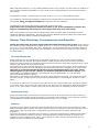
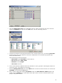
How to create a new project
To create a new project for the Processor Expert™ plug-in, select the New command in the File
menu of the CodeWarrior Main menu. Select the Stationary for your processor and in the dialog
window, type your project name in the Project edit box. You can also select desired location for the
project. After clicking the "OK" button, select the appropriate CPU in the Processor Expert™ folder.
The new project will be created. If no other project is already open in the Processor Expert™ plugin, the plug-in starts and the new project template will be inserted to the plug-in environment.
More information on how to start a new project can be found in the chapter Quick Start and in the
Tutorial course.
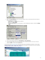
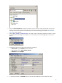
Compiler and Linker settings
To set the compiler and linker options, select the command " {TargetName} Settings " in the "Edit"
menu in the Code Warrior main menu. You can find linker and compiler specific settings in the
"Target" and "Linker" folders. The command " {TargetName} Settings " is not available when no
project is open.
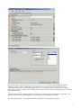
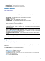
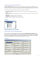
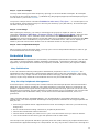
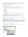
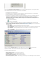
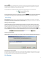
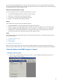
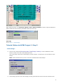
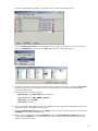
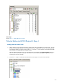
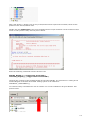
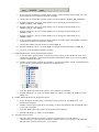
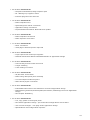
Where to find source code and user modules
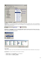
Processor Expert generates all drivers during the code design process. The generated files are
automatically inserted into the active (default) target in the CodeWarrior project. Generated files
corresponding to Embedded Beans™ can be accessed in the "Generated Code" folder in the "Files"
tab in the Code Warrior project window. The other files, intended to be modified by users, are
generated into the "User modules" folder in the "Files" tab in the Code Warrior Project window. A
user can also add his own specific source code files into this folder. If the linker setting of the
default target does not match the CPU in the Processor Expert™ project, the user is asked whether
to automatically set the correct linker settings in the default target or to create a new target with
correct linker settings. In the latter case the files will be generated in the new target (more
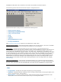
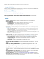
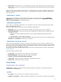
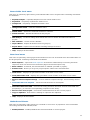
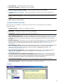
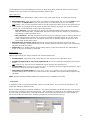
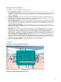
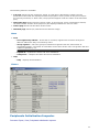
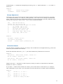
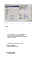
information about the CodeWarrior Project panel can be found the CodeWarrior documentation).
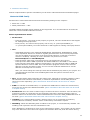
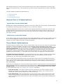
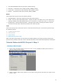
The following picture shows the CodeWarrior Project panel.
4
Benefits of Embedded Beans and Processor Expert
Technology
The key benefit of Embedded Beans™ is the same as using components in software design
environments like Microsoft Visual Basic or Borland Delphi. In comparison with components used
within these products, Embedded Beans™ provide hardware encapsulation in the form of platformindependent standard. Different players in the embedded market should benefit from such
standartisation approach.
Microprocessor producers
Each year microprocessor producers introduce many new microprocessor families or derivatives. As
the complexity of microprocessors increases, programmers must handle more and more registers to
get the required functionality. Classical development tools usually do not support the rapid
prototyping phase of design and classical programming languages are not able to efficiently
describe the on-chip peripherals structure efficiently. On the other hand, microprocessors producers
need to speed up the learning, design and coding processes for their customers.
For the designer, Processor Expert and its configuration and code generation features completely
eliminate the necessity to be occupied with hardware dependencies. Processor Expert™ could even
suggest the right member of a microprocessor family for the specific application.
Producers of intelligent peripheral I/Os and other devices
Complex and feature -rich peripherals and controllers require a great of effort to use them
efficiently, even if device drivers are supplied by the factory. But imagine the possibility of
supporting customers with components providing a standard software interface that allows building
applications and easily uses new hardware device features.
And yes, Processor Expert™ environment allows this - customers can easily download new
components from the internet and install them into Processor Expert™.
Producers of hardware of microprocessor systems
Microprocessor boards that are to be programmed by a customer must be well supported by
software. Processor Expert™ can handle software configuration and generation of drivers for
microprocessor devices and off-chip peripheral devices. Creating an application using Processor
Expert™ takes usually 70% less time than with standard Integrated Development Environments
(IDEs) containing only a source code editor/compiler/debugger.
5
Producers of compilers, hardware emulators and simulators
Processor Expert™ is able to cooperate with other tools and IDEs because it works on a higher
level of abstraction. Tools suppliers can increase attractiveness of their tool with Processor Expert™
features.
Producers of programmable logic (FPGA,..)
When a customer designs his own FPGA-based peripheral, it is possible to "bean-it" - to include its
standard form into the Processor Expert Embedded Beans™ palette. Then the design could be
reused in software and supplied to FPGA designer customers with full software support.
Producers of OS
Processor Expert™ can be used to build an OS kernel or OS drivers. Also, thanks to Processor
Expert™ open component architecture and support of pure software beans, Processor Expert™ can
be used to build applications benefiting from underlying operating system services.
Educational institutes
Microprocessor-oriented courses can benefit from the concentration of knowledge of microprocessor
structures and hardware independence delivered by Processor Expert™. Design of applications
starts from a definition of functionality, which is then obtained very quickly by building the
application from Embedded Beans™. Students can get the the results very fast without struggling
with problems that are not related to the subject of the course (e.g., compiler bugs, errors in the
documentation and so on).
Hardware and software developers
Shortening of the design and learning phase, speeding up the deployment of new components, full
use of hardware using tested software components, reducing time and cost of design - all these
are keys to success provided by Processor Expert™.
Features
PE based tool solution offers the following advantages to Motorola CPU
customers:
l
l
In all phases of development, customers will experience substantial reductions in
¡
development cost
¡
development time
Additional benefits in product development process are
¡
Integrated development environment increases productivity
¡
Minimized time to learn Motorola CPU
¡
Rapid prototyping of entire applications
¡
Modular and reusable functions
¡
Easy to modify and port implementations
¡
Design-time verifications
Integrated development environment increases users' productivity
l
"This tool lets me produce system prototypes faster because the basic setup of the constroller
is easier. This could mean that I will implement more of my ideas into a prototype application
having a positive effect on the specification-, analysis - and design-phase. PE justifies its
6
existence even when used for this purpose alone!"
l
l
"This system frees you up from the hardware considerations and allows you to concentrate on
software issues and resolve them thoroughly."
"Very good for CPUs with embedded peripherals. It significantly reduces project development
time."
The following are the primary reasons why users feel that way:
l
PE has built -in knowledge (internal definition) of entire µC with all its integrated peripherals.
l
PE encapsulates functional capabilities of µC elements into concepts of configurable beans.
l
l
l
l
PE provides intuitive graphical UI, displays the µC structure, and allows user to take advantage
of predefined and already verified beans supporting all typically used functions of the µC.
Application's are designed by defining the desired behavior using the components settings,
drag&drop selections, utilizing the generated methods and events subroutines, and combining
the generated code with user code.
PE verifies the design based on actual µC resource and timing contentions.
PE allows the efficient use of the µC and its peripherals and building of portable solutions on a
highly productive development platform.
Minimized time to learn the CPU
There are exciting possibilities in starting a new project if the user is starting from ground zero
even if the user is using a new and unfamiliar processor.
l
User is able to utilize the µC immediately without studying the µC's documentation.
l
User is able to implement simple applications even without deep knowledge of programming.
l
PE presents all necessary information to the user using built -in descriptions and hints.
l
PE has built -in tutorials and example projects.
Rapid prototyping of entire applications
"Processor Expert allows users to try several different approaches in real time, picking and
choosing the best of each for the final solution. Users are not confined to a pre -determined linear
track to a solution."
l
Easy Build of application - based on system functional decomposition (top-down approach)
l
Easy/Auto CPU selection
l
Easy/Auto CPU initialization
l
Easy/Auto initialization of each internal peripheral
l
Simple development of reusable drivers
l
Simple implementation of interrupt handlers
l
Inherited Modularity and reuse
l
Inherited ease of implementation of system hardware and software/firmware modifications
Modular and reusable functions
Processor Expert™ greatly decreases the start-up time and minimizes the problems of device
idiosyncrasies.
l
It uses the concept of a function encapsulating entity (called Embedded Bean™) with
supporting methods and events
l
Uses a library of predefined beans
l
Uses a concept of device drivers and interrupt handlers that are easy to reapply
7
l
Uses a concept of well documented programming modules to keep the code well organized and
easy to understand
Easy to modify and port implementations
PE allows optimal porting to a previously unused processor.
l
Supports multiple devices within a project and makes it extremely easy to switch them
l
Supports desired changes in the behavior of the application with an instant rebuild
l
Supports interfacing of Metrowerks CodeWarrior
Concepts
Processor Expert has built-in knowledge (internal definitions) of the entire CPU with all of its units
and integrated peripherals. The CPU units and peripherals are encapsulated into configurable
components called Embedded Beans™, each of them providing set of useful properties, methods
and event subroutines.
An intuitive and powerful User Interface (UI) allows the user to define the system behavior in
several steps. Simple system can be created just by selecting the necessary beans, setting their
properties to required values and maybe also dragging and dropping some of their methods to the
user part of the project source code.
PE key components
l
Graphical IDE
l
Built-in detailed design specifications of Motorola devices
l
Code generator
PE key features
l
CPU selection from multiple CPU derivatives available
l
CPU pin detailed description and structure viewing
l
Configuration of functions and settings for the selected CPU and its peripherals
l
Definition of system behavior during initialization and at runtime
l
Design of application from pre -built functional components (called BEANS)
l
Design of application using bean methods (user callable functions) and events (templates for
user written code to process events, e.g. interrupts)
l
Customization of beans and definition of new beans
l
Tested drivers
l
Library of components/beans for typical functions (including virtual SW beans)
l
Verified reusable beans allowing inheritance
l
Verification of resource and timing contentions
l
CPU resource meter/balancing
l
Concept of project panel with ability to switch/port between CPU family derivatives
l
Code generation for components included in the project
l
Implementation of user written code
l
Interface with Metrowerks CodeWarrior
Terms and definitions used in a Processor Expert
Bean - An Embedded Bean™ is a component that can be used in Processor Expert™. Embedded
8
Beans™ encapsulate the functionality of basic elements of embedded systems like CPU core, CPU
on-chip peripherals, standalone peripherals, virtual devices and pure software algorithms and wrap
these facilities to properties, methods, and events (like objects in OOP). Beans can support several
languages (ASM, AnsiC, Modula and others) and the code is generated to the selected language.
Bean Inspector - window with all parameters of a selected bean: properties, methods, events.
CPU Bean - bean which encapsulates CPU core. CPU beans are displayed in Bean Inspector, where
the CPU parameters can be modified and much more.
Driver - bean's driver. Drivers are the core of Processor Expert code generation process. Processor
Expert uses driver to generate code for driving internal or external peripheral considering bean
settings. Bean can encapsulate one or more drivers.
Events - an Event function is used for processing an event (e.g., an interrupt, buffer overflow) by
user-written code.
Note: In Processor Expert™, an event function is the only way to process an interrupt by an user
code, because all the interrupts are handled by routines generated by Processor Expert™. These
interrupt service routines can not be modified by the user. But just before returning, these routines
call the appropriate event function, which is supposed to (although it does not necessarily have to)
contain the user code.
External user module - external source code attached to the PE project. The external user module
may consist of two files: implementation and interface (*.C and *.H).
Internal peripherals - internal devices of the CPU (ports, timers, A/D converters etc. usually
controlled by CPU core using special registers).
ISR - Interrupt Service Routine - code, which is called when an interrupt occurs.
Methods - user callable functions or sub-routines. The user can select which of them will be
generated and which not. Selected methods will be generated during the Code generation process
into the bean modules.
Module - source code module. Could be generated by processor Expert (Bean modules, CPU
Module, events.c) or created by the user and included in the project (user module).
OOP - Object-oriented programming (OOP) was invented to solve certain problems of modularity
and reusability that occur when traditional programming languages such as C are used to write
applications.
PESL (Processor Expert Support Library) is dedicated to power programmers, which are familiar
with CPU architecture - each bit and each register. PESL provides the macros to access the
peripherals directly, so PESL should be used only in some special cases. You can find more
information in PESL documentation.
Peripheral bean - encapsulates whole initialization of appropriate peripheral. Doesn't contain any
methods and events. The rest of the device driving code needs to be written by hand using either
PESL or direct control of the peripheral registers.
Popup menu - this menu is displayed when the right mouse button is pressed on some graphical
object.
Properties - parameters of the bean. Property settings define which internal peripherals will be
used by the bean and also initialization and behaviour of the bean at runtime.
Target CPU - the CPU derivative used in a given project.
Template - Bean Template is a bean with preset parameters.
User-defined Bean Template - User-defined bean template is a bean with preset parameters
saved under a selected name. Also the name of the author and short description can be added to
the template.
9
User module - source code module created or modified by user. (Main module, event module or
external user module).
User Interface
Menu
Processor Expert menu is integreated in the CodeWarrior IDE menu. It contains a new item named
"Processor Expert".
See Processor Expert plug-in Main menu page for description of individual items.
Windows
The user interface of Processor Expert consists of the following windows (integrated in
CodeWarrior IDE):
l
l
l
l
l
l
l
l
l
l
l
l
l
Project panel with beans (including CPU(s)), external modules and documentation included in
project. Project Panel supports several configurations of one project.
Bean Selector - shows all supported beans in the appropriate version of the Processor Expert
including CPU beans and bean templates.
Inspector - a window which allows user to setup Beans and Configurations of the project.
Error window - a window with errors, warning messages and hints from project checking,
generation and from external tools
Target CPU - a window graphically showing CPU package, structure and beans connected to
internal peripherals.
CPU Structure - a window showing the target CPU's internal devices.
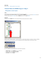
Resource Meter - a window displaying the amount of the target CPU's resources already
allocated.
Memory Map - a window showing the CPU address space and internal and external memory
mapping.
CPU Types Overview - a window displaying the list of the database's CPUs supported by the
current version of Processor Expert.
CPU Parameters Overview - a window providing access to the CPU's database.
Installed Beans Overview - this window contains information about installed beans in the
current version of Processor Expert.
Peripherals Usage Inspector - a window showing which bean allocates which on-chip
peripheral.
PDF Search - a window allows user to quickly browse in PDF documentation for the CPU.
Dialogs
There are the following dialogs for setting the Processor Expert environment:
l
Environment Options - Processor Expert plug-in environment options
l
Tools Setup - setup dialog box for the tools and the tools menu
There are the following dialog for setting the Processor Expert project:
l
Project Options - project options are options concerning the current project and project options
for the current CPU.
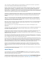
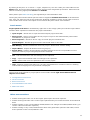
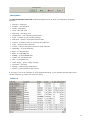
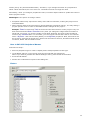
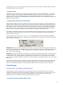
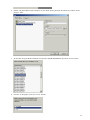
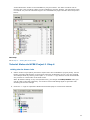
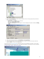
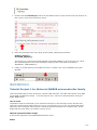
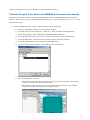
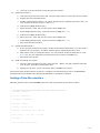
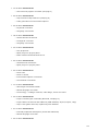
Main Menu
The Processor Expert Plug-in is integrated into the Metrowerks CodeWarrior IDE application. The
10
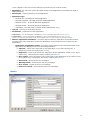
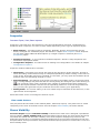
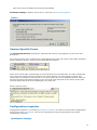
CodeWarrior IDE main menu contains a new menu item named "Processor Expert".
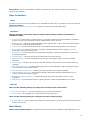
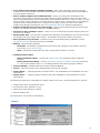
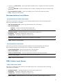
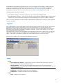
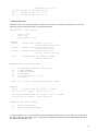
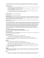
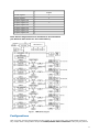
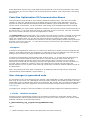
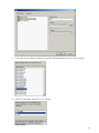
The following picture shows the Processor Expert's integrated menu:
The Processor Expert's plug-in menu consists the following items:
l
Open Processor Expert
l
Code Design "ProjectName.mcp"
l
Undo Last Code Design
l
View
l
Tools»
l
Update»
l
Bring PE Windows to Front
l
Arrange PE Windows
Note: Processor expert's help is placed in the Codewarrior's 'Help' menu.
Open Processor Expert - opens the Processor Expert for the current project. The item is available
only when Processor Expert isn't already being used for a current project.
Code Design - Invokes code generation for the current project. The generated files are
automatically inserted into the active (default) target in the CodeWarrior's project. Generated files
corresponding to the Embedded Beans can be accessed in the "Generated Code" folder in the
"Files" tab in the CodeWarrior project window. The other files, intended to be modified by the user,
are generated into the "User modules" folder in the "Files" tab in the CodeWarrior project window.
A user can also add specific source code files into this folder. If the linker setting of the default
target does not match the CPU in the Processor Expert project, the user is asked whether to set
automatically correct linker settings in the default target or to create a new target with correct
linker settings. In the latter case the files will be generated in the new target (see also chapter
Code Design).
Undo Last Code Design - if the project is generated with errors, it returns to the last successful
generation; otherwise, it returns to the previous successful generation. The files not generated in
previous code generation are also automatically removed from the CodeWarrior's Project panel.
View
l
l
l
Project Panel - displays the Processor Expert plug-in Project panel.
Inspector- displays inspector window for the currently selected item of the project (Bean, CPU
bean, Peripheral bean, Configuration)
Bean Selector - shows the Bean Selector. Bean Selector shows all supported beans in the
appropriate version of the Processor Expert plug-in including CPU beans.
11
l
l
l
l
Target CPU Package - displays the Target CPU Window in CPU Package view. This window
displays the target CPU (CPU selected as destination) with its peripherals and pins.
Target CPU Block Diagram - displays the Target CPU Window in Block Diagram view. This
window displays the target CPU (CPU selected as destination) block diagram with its
peripherals.
Error Window - displays the Error window. This window displays errors, warnings, and hints.
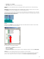
Resource Meter - displays the Resource Meter window. The Resource Meter shows the current
status of a chip resources usage (or availability).
l
Target CPU Structure - displays the schematic CPU Structure.
l
Peripherals Usage Inspector - shows the CPU Peripherals Usage Inspector.
l
l
l
l
l
Peripheral Initialization Inspector - opens the Peripheral Initialization Inspector window for
the Target CPU. (this command is available only if a target CPU is selected)
Installed Beans Overview - displays a list of installed beans and CPUs with additional
information about drivers and projects with typical settings.
CPU Types Overview - displays the CPU overview window with a tree of supported CPUs (the
active CPU's package is displayed in the Target CPU Window).
CPU Parameters Overview - displays the CPU parameters overview table and the query
dialog that provides help for the selection of the most adequate processor.
Memory Map - opens the Memory Map window. This window shows the CPU address space
and internal and external memory mapping.
Tools
l
l
Tool #1
Tool #2.... - optionally, any other external tool can be added. The tools can be added, modified
or deleted in the "Tools Setup" dialog.
Note: Bean Wizard can be added also to the Tools menu. Help for the Bean Wizard can be found in the
Bean Wizard.
l
Tools Setup - allows external tools to be included in the Processor Expert's plug-in
environment. The tools may then be accessed via the "Tools" menu. The setting changes will
take effect after the restart of the CodeWarrior application. See tools setup for details.
Update
l
l
Update Processor Expert from Package - this command allows you to update or add new
beans from compressed packages (*.PEupd) that can be downloaded from the Processor
Expert web site . It is possible to select more beans in the selected directory using a multiselect function. To add more beans select the requested bean using mouse and holding down
CTRL (or Shift) key.
Check Processor Expert Web for updates - check for updates on the Processor Expert web
site. If there is any news for your version, Processor Expert offers you to open the
corresponding page in a default Internet browser.
Bring PE Windows to Front
12
Sets the main Processor Expert's windows to the front on the screen.
Arrange PE Windows
Arranges all open windows to the default placement on the screen. (Project Panel, BeanSelector,
CpuPanel, Error Window, ResMeter, Bean Inspector)
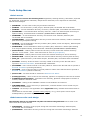
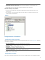
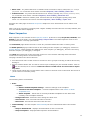
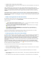
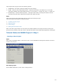
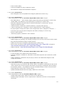
Environment Options
CodeWarrior main menu | Edit | {TargetName}Settings...
There are options in the "Target settings" window for the configuration of the Processor
Expert's plug-in environment.
Options
l
Autosave desktop - desktop is saved in statement when exiting Processor Expert.
l
Encode desktop file
l
¡
For each project - saves desktop setting for each project (recommended)
¡
For each directory - saves desktop setting for each directory.
¡
Only one global - saves only one global desktop setting .
New bean - the following settings concern the addition of a new bean to the project (Using
Bean Selector).
¡
¡
¡
l
¡
¡
l
l
l
l
l
l
Select bean template - if the new bean has templates, a selection menu appears to let
you choose between the default bean and its templates.
Auto connect bean - Processor Expert tries to connect the new bean to adequate on-chip
peripherals (if required for the bean).
Enable new bean - this settings influences decision if the bean will be enabled in a specific
configuration. (It is used only if the project does have multiple configurations defined.)
¡
l
Auto open bean inspector - the bean inspector of a new bean is automatically opened.
in all configurations - added bean will be automatically enabled in all configurations.
in active config only - new bean will be automatically enabled in current active
configuration only.
always ask - user will be asked whether to enable bean or not.
Auto save files before code design - Files will be automatically saved when user runs Code
Design.
Assign bean name to peripheral name - if you change a property and new value is used
correctly (not overlapped with another setting), then the property Bean Name is automatically
set to this value. (see also Bean Inspector)
Show progress on code design - during code generation, displays a window with a progress
bar.
Show all sources after code design - after code generation, all sources generated by
Processor Expert (i.e. all sources except main and on-event code files) are displayed in the File
Editor.
Show user modules after code design - after code design, displays in the File Editor all the
modules that may be edited by users (main and on-event code).
Undo for code design - enables the Processor Expert | Undo Last Code Design command
Make cause code design if needed - when Make is launched, code generation is performed if
changes have occurred since the last code generation.
13
l
l
l
l
l
l
l
Go to method code instead of method comment - after code generation, double-clicking a
method in the Project Panel positions the File Editor's cursor on the method's code instead of
on the method's comment.
Ask to rename periphery from unknown name - when you change the destination CPU,
Processor Expert tries to connect the project beans to the peripheral of the new CPU. If the
name of the peripheral to which a bean was connected does not exist on the new chip, you will
have to select a new peripheral. Processor Expert will then ask to rename this new peripheral
with the name of the previous one, so that you may later go from one CPU to the other
without any settings modification (see CPU Peripherals Name for detailed explanation).
Delete unused files from previous code design - remove all unused files from previous code
design (for example renamed, deleted or disabled beans).
Set Focus to Error window on error - when an error is detected, Processor Expert sets focus
on the error window.
Bitmap under CPU - you may here indicate the path name of the BMP picture you wish to have
as background of the Target CPU window. The bitmap can be either tiled or stretched.
Show producer's logo if exists - producer's logo is set as background (wallpaper) of the
Target CPU window, provided the logo is available.
Bitmap - select bitmap's position
¡
¡
l
Stretched - the bitmap is positioned in the center and enlarged in accordance with the
size of the Target CPU window.
Tiled - repeat the bitmap until the entire Target CPU window is covered.
Default property values
¡
¡
Delete all default values - removes all default values for properties and permanent
settings.
Delete permanent settings - remove permanent settings of default values for properties,
i.e. "do not use default value" or "use always default value during project loading".
l
Factory Settings - default settings of the Environment Options
l
Revert - returns to the previous setting before the current changes
l
l
Import Panel... - importing panel from XML format - see CodeWarrior documentation for more
information
Export Panel... - exporting panel to XML format (see CodeWarrior documentation for more
information)
The following options are set globally no matter what is set in the " Encode desktop file" options:
l
Assign bean name to peripheral name
l
Set Focus to Error window on error
l
Make cause code design if needed
l
Encode desktop file
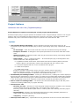
The options are not saved to the desktop.
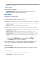
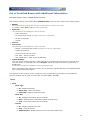
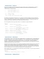
Picture
14
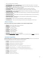
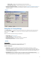
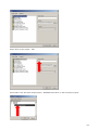
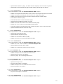
Project Options
CodeWarrior main menu: Edit | {TargetName}Settings...
Project Options are options concerning the current project (all target CPUs)
Processor Expert plug-in project options are available in the "Target settings" window. The "Project
options" item is in the folder Processor Expert as a "dummy" pre-linker. The Project options are
available only when a Processor Expert project is opened in the Code Warrior IDE.
Options
l
User modules during code design - specify whether the main and events code may be
overwritten by the Processor Expert plug-in during code design (they may contain user-written
code!)
¡
¡
¡
¡
Do not change - main and events code will never be overwritten during code design
Prompt to overwrite - a dialog box will request permission to overwrite main and events
code
Always overwrite - main and events code may be overwritten during code design without
any confirmation request
Smart update - (default) "intelligent option" - Processor Expert plug-in distinguishes userwritten code from code designed code.
n
it updates modules' and events' names that have been modified (within Processor
Expert's plug-in environment) in both code designed and user-written code.
n
it removes imports that are no more included to the project.
n
it adds new imports.
n it adds new events.
Except for modules' and events' names, the user-written code is kept intact.
External modules in folder "user modules" added to project are renamed too.
Note: The module description in comment is not updated in this mode.
l
l
l
Automatically use existing modules - unless you check this box, a dialog box will be displayed
during the first code design in order to ask if you wish to use existing Main and Events modules
(Main module must have the project's name and Events modules must have the name defined
in the Events page of the Bean Inspector of the beans) instead of generating new files.
Ask to create non-existing subdir - if is checked, the Processor Expert plug-in will ask you to
create non-existing subdirectory in project directory.
Directories for code
¡
¡
¡
l
Directory for code - directory for code designed modules and user modules. User modules
(event modules and main program body) can contain user-written code.
Directory must be the absolute path name or relative path name starting from the project
directory.
Documentation - directory for code designed project text help (absolute path name or
relative path name starting from the project directory).
Temporary - temporary directory.
Interrupt vector table (IVT) - specification for the generation of the IVT. IVTs are described in
15
the Interrupt Vector Table page. The specification consists of the following fields:
l
Table type - specifies the location and the structure of the interrupt vector table.
¡
¡
¡
l
l
l
l
generate into ROM - only for standalone applications; there is only one IVT in ROM.
generate into RAM - only for standalone applications; there is one IVT in ROM and one in
RAM (only for non-bean interrupts).
external kernel - only for applications running under an external kernel. In that case we
must enter the other IVT parameters.
Vector type - type (structure) of a single vector in IVT; it be: address (ADD) or jump (JUMP)
instruction with address (for external kernel only).
Interrupt vector table address - base address of the table; the address of the first element of
table (for external kernel only).
Number of interrupt vectors - number of vectors in the table (for external kernel only).
Interrupt vector step - distance between neighboring vectors in bytes (for external kernel
only).
l
Interrupt vector size - length of a vector in bytes (for external kernel only).
l
Number format - chose decimal or hexadecimal number format in drivers
l
Generation of bean modules - specifies how to treat user changes in generated bean
modules. (See User changes in generated code for more details.
¡
¡
Generate manifest constants - Enables/disables generation of the CH file, which contains
the list of manifest constants for each bean module.
Preserve user changes - After settings this option it's necessary to generate the code
and after that Processor Expert can detect and preserve changes in the generated code of
bean modules.
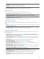
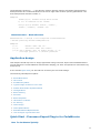
Picture
Interrupt Vector Table
An interrupt vector is a pointer to an interrupt handling subroutine.
An Interrupt Vector Table (IVT) is a table (list) which contains single interrupt vectors. Each
interrupt corresponds to one interrupt vector. IVT may be:
l
l
placed in ROM - usually first-level IVTs: the jump to the right vector is done by hardware
placed in RAM - usually second-level IVTs: the jump to the right vector is done by software
first-level interrupt handling subroutine
16
l
hard-wired - first-level IVT; it is not possible to change vectors because they are not placed in
ROM, but hard-wired on the chip (each interrupt has its jump address that cannot be changed
in any way)
Each processor that can handle and process interrupts has a first-level IVT (in ROM or hard-wired).
Whether it has a second-level (or third-level, ...) IVT depends on software (kernel or application's
interrupt system).
Standalone vs. Kernel
There are two approaches to application development: one may develop either a standalone
application for a naked system (everything is included in the project) or an application running
under an external kernel (or operating system).
Standalone applications
In the case of a standalone application, all is possible. One may create the contents of the whole
ROM - including first-level IVT.
Processor Expert offers two types of IVT for standalone applications:
l
l
ROM table - there is only a first-level IVT in ROM; no interrupt vectors can be changed.
ROM and RAM table - there is a first-level IVT in ROM and a second-level IVT in RAM. Vectors in
the ROM IVT points:
¡
directly to the user handling subroutine - for interrupts assigned by Processor Expert
beans.
¡ to the RAM IVT - for the other interrupts.
The RAM IVT contains only vectors of non-bean interrupts; those vectors can be changed using
SetVector and GetVector methods of CPU module.
Applications running on a kernel
In the case of an application running on a kernel, the application can use services offered by the
kernel but cannot change system values used by the kernel. Developers of the kernel have created
its own first-level IVT in ROM and it may not be changed. However, the kernel offers a second-level
IVT in RAM; its vectors may point to our code.
Processor Expert knows nothing about the kernel and its IVT and therefore it must be described in
Project Options.
Processor Expert needs to know:
l
vector type - only address or jump instruction with address
l
base IVT address - address of the first vector in the table
l
number of vectors to be generated to the table
l
vector step - distance between addresses of neighboring vectors
l
vector size - width of the vector (in bytes)
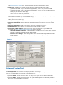
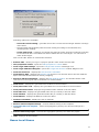
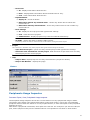
Tools Setup
Processor Expert | Tools | Tools Setup
Tools Setup - allows include tools in the Processor Expert environment. The tools may then be
accessed via the Tools menu.
Options
l
Tool name - name of the tool, as it appears in the Tools menu.
l
Visible in Tools menu - whether the tool is available in the Tool menu (it may not be necessary
17
to let it appear in the menu if the settings are meant only for internal make)
l
Application - the full name (name and path name) of the application (executable file, EXE or
COM extension).
l
Working dir - working directory of the application
l
Application type
¡
MS-DOS real - MS-DOS real mode application.
¡
MS-DOS protected - MS-DOS protected mode application.
¡
Windows 16-bit - 16-bit MS Windows application.
¡
Windows 32-bit - 32-bit MS Windows application.
¡
Autodetect - auto detection (enabled under Windows NT only).
l
Hot Key - Hot Key for launching the tool.
l
Parameters - parameters of the application.
l
Input file(s) - only for backward compatibility, value of the $OUTPTH macro (see macros).
l
Output file(s) - only for backward compatibility, value of the $IN?PTH macro (see macros).
There is no warranty that these items will be supported in the next version of Processor Expert.
l
Wait for application termination - Processor Expert waits for application termination before
executing any other operation (it has the advantage of reserving the error window for the
application).
¡
Redirection of application output - Processor Expert captures the standard output of the
application and displays errors in the Message Window.
n
n
n
Input file - name of the input file for the application. If you don't specify any, a
temporary file will be created (see macros).
Output file - name of the file for the redirection of the application output. If you don't
specify any, a temporary file will be created (see macros).
Error output - name of the file for the redirection of the application error output. If you
don't specify any, a temporary file will be created (see macros).
n
Hint format - format of the hint messages.
n
Warning format - format of the warning messages.
n
Error format - format of the error messages.
n
Fatal error format - format of the fatal error messages.
Picture
18
Tools Setup Macros
Global macros
Global macros are used in the following items: Application, Working directory, Parameters, Input file
(s), Output file, Input files for redirection, Output file for redirection, Error output file for redirection,
Format of all messages
l
$PRJNAME - current name of the project without extension
l
$DIRPRJ - current directory of the project, absolute path, terminated with a backslash
l
$DIRDRV - current destination directory of drivers, absolute path, terminated with a backslash
l
l
l
l
l
l
$DIRRELDRV - current destination directory of drivers, relative or absolute path from Project
Options setting, terminated with a backslash ($DIRRELEVENT+$EVENTTODRV)
$DIREVENT - current destination directory of main and event modules, absolute path
terminated with a backslash
$DIRRELEVENT - current destination directory of main and event modules, relative or absolute
path from Project Options setting
$DIRBIN - current destination directory of binary files (maker, linker and object), absolute path
terminated with a backslash
$DIRRELBIN - current destination directory of binary files, absolute or relative path starting
from Project Options setting, terminated with a backslash ($DIRRELEVENT+$EVENTTOBIN)
$DRVTOEVENT - relative path from drivers directory to main and event modules directory
(drivers - Driver subdir., event - Main and event dir. from Project Options)
l
$EVENTTODRV - relative path from main and event modules directory to drivers directory
l
$EVENTTOBIN - relative path from main and event modules directory to binary files directory
l
$DIR_PE - system directory of Processor Expert, absolute path, terminated with a backslash
l
l
l
$FILEDIR - directory of the file that is currently edited or directory of the file that will be
opened in External Text Editor, terminated with a backslash.
$FILENAME - name of the file that is currently edited or name of the file that will be opened in
External Text Editor (including extension).
$FILENAM - name of the file that is currently edited or name of the file that will be opened in
External Text Editor (without extension).
l
$GOTOLINE - line that should be selected in External Text Editor.
l
$?FILE(Question) - name of the file set manually, Question is displayed to the title of window
l
l
l
l
$?PARAM(Question,Default) - parameters set manually, Question is displayed to the title of
window, Default is a default value
$COMSPEC - setting of the COMSPEC variable in the Windows environment
$INTERNALMAKE - can be used only in parameters, indicates that the tool is meant only for
the start of internal make
#MAKE# - can be only in the application name (Application field), indicates that internal make is
started.
Parameters for internal make: [makefile name] [target] [-A+|-], where option A turns on/off
autodependency. (Processor Expert standalone only)
Global macros after code design
The following macros are supported only after successful code generation.Can be used in the
same items as the Global Macros.
l
l
$GENDIRPRJ - directory of the project during last successful code design, absolute path,
terminated with a backslash
$GENDIRDRV - destination directory of drivers during last successful code design, absolute
19
path, terminated with a backslash
l
l
$GENDIRRELDRV - same as $GENDIRDRV during last successful code design, only relative
path ($GENDIRRELEVENT+$GENEVENTTODRV)
$GENDIREVENT - destination directory of main and event modules during last successful code
design, absolute path terminated with a backslash
l
$GENDIRRELEVENT - same as $DIRRELEVENT during last successful code design
l
$GENDIRBIN - destination directory of binary files during last successful code design
l
l
l
l
$GENDIRRELBIN - same as $GENDIRBIN during last successful code design, only relative path
($GENDIRRELEVENT+$EVENTTOBIN)
$GENDRVTOEVENT - relative path from drivers directory to main and event modules directory
during last code design
$GENEVENTTODRV - relative path from main and event modules directory to drivers directory
during last code design
$GENEVENTTOBIN - relative path from main and event modules directory to binary files
directory during last code design
l
$GENPRJNAME - name of the project during last successful code design
l
$GENMAKEFILE - name of current makefile (Processor Expert standalone version only)
Macros in format
List of macros that can be used for definition of tool output messages format:
l
$ERRPTH - name of file where errors were found
l
$ERRMSG - full / partial error message
l
$FIRROW - first row position
l
$FIRCOL - first column position
l
$LASROW - last row position
l
$LASCOL - last column position
l
$MSGSKP - skip next string
l
$MSGEND - end/continuation of error message
l
$MSGSTR"string1"string2 - string1 is written to error message and then string2 is skipped as
in command $MSGSKP
Backward compatibility
The following macros are supported only for backward compatibility. There is no warranty that
they will be supported in the next version of Processor Expert.
l
$REDDIR - full path name of project directory for redirection
l
$REDINP - full path name of input file for redirection
l
$REDOUT - full path name of output file for redirection
l
$REDERR - full path name of error file for redirection
l
$IN?DIR - directory of input file, "?" is a number of input file from interval 0..9
l
$IN?NAM - name of input file, "?" is a number of input file from interval 0..9
l
$IN?EXT - extension of input file, "?" is a number of input file from interval 0..9
l
$IN?PTH - full path name of input file, "?" is a number of input file from interval 0..9
l
$OUTDIR - directory of output file
l
$OUTNAM - name of output file
l
$OUTEXT - extension of output file
l
$OUTPTH - full path name of output file
20
l
$DRIVERS(FORMAT) - list of the all generated drivers
l
$EVENTS(FORMAT) - list of all generated event modules
l
$SHARED(FORMAT) - list of all generated shared modules
Help and manuals
Help | Processor Expert >
This menu and contains following items:
l
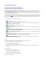
Processor Expert Help - the start page of the Processor Expert plug-in help.
l
Introduction - introduction to Processor Expert.
l
Benefits - who Processor Expert may benefit.
l
User Interface - description of Processor Expert plug-in environment.
l
Tutorial - tutorial course.
l
Quick Start - how to start with Processor Expert plug-in.
l
Embedded Beans - index page of the Embedded Beans documentation.
l
Embedded Beans Categories - index page of the Embedded Beans Categories.
l
l
l
l
l
l
Supported CPUs, Compilers and Debuggers - list of CPUs/Compilers/ Debuggers supported in
the current version of Processor Expert plug-in.
PESL Library User Manual - PESL Library Documentation
View Readme - Displays informations about used Processor Expert plugin version, basic
installation instructions, content of installation, FAQ, known problems and limitations and other
related informations.
Search in PDF Documentation of the Target CPU - displays PDF documentation of the current
CPU in the PDF Search window. It is possible to search any keyword in the CPU documentation
based on the original manufacturer's CPU manual.
Go to Processor Expert Home page - display Processor Expert home page in default Internet
browser.
About Processor Expert - displays information about the Processor Expert product version for
the target CPU family and current version of Processor Expert IDE.
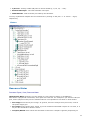
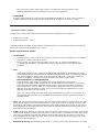
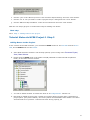
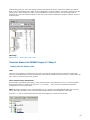
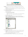
Project Panel
Processor Expert | View | Project Panel
Processor Expert Project Panel is a tab in CodeWarrior's project window (panel). When the 'Project
Panel' is noticed in Processor expert documentation the 'Processor Expert Project Panel' is
understood.
The Project panel shows the application components:
l
Configurations of the project.
l
CPUs (CPU beans) included in the project
l
Embedded Beans included in the project
l
Documentations (list of files attached into project as documentation, with relative or absolute path. No
actions are made with theese files.)
l
PESL methods (if PESL is enabled)
CPUs and Beans are organized in folders in a tree. You can expand and collapse a tree's branches
21
by clicking on the plus "+" or minus "-" signs, respectively. You can create your own folders in the
Beans folder and move beans between them using mouse drag and drop function. Each bean has
subtree containing appropriate Events and methods.
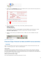
Faulty beans (see Bean Checking) are signaled by a red exclamation mark
The Project panel window allows quick access to supported methods and events of each bean as
well. User can easily put call to any method by dragging method by mouse to the editor of source
code. Double click on the event opens source code on the place of the event handler.
Local menus
Project panel local menu is accessible by right click on the empty (white) area of the Project Panel.
Contains basic operations related to the project and beans.
l
l
Open Project - Allows user to open Processor Expert project from disk.
Save Project - Saves current state of the project. Project is also automatically saved when
CodeWarrior or project is closed.
l
Save Project As - Allows to save a copy of current project to another file.
l
Reload Project - Reloads project from the last saved state on the disk.
l
Add Bean(s) - Allows to add beans from the project. Shows bean selector dialog.
l
Import Beans - Imports all beans from a file (project).
l
Export Beans - Exports selected beans including settings to the file. It's possible to insert
them into another project using Import Beans command.
l
Cut - Cuts selected bean with it's settings to the clipboard.
l
Copy - Copies selected bean with it's settings to the clipboard.
l
Paste - Insert bean from the clipboard to the current project.
l
Help - Displays related information for currently selected bean or method. If there is nothing
selected this help page for Project Panel is displayed.
Local menus of the objects in project panel are accessible with a right mouse button click on
object's icon or label.
l
Configurations local menu
l
CPUs local menu
l
Beans local menu
l
Documentations local menu
l
PESL local menu
Other mouse actions
l
l
l
l
Double-clicking the bean icon in the Project panel opens the bean inspector
Double-clicking the bean name in the Project panel allows you to edit the name of the selected
bean
Double clicking on any event/method enable/disable icon changes its enable/disable state (you
can do it also via the bean inspector)
Double clicking on any event/method name after code generation opens the file editor/viewer
at the position of the event/method's code
22
l
l
placing the mouse over any event/method icon/name displays the event/method's and
parameter's description and syntax
placing the mouse over any bean icon/name displays the bean description
Multiselect and drag'n'drop features:
l
l
you may select several items using the Ctrl and Shift key together with cursor key or left
mouse button
you may drag'n'drop components within the Project Panel to reorganize component trees
(CPUs, Beans, Documentation)
Picture
Configurations Local Menus
Configurations folder local menu
This menu is opened by right-clicking on the Configurations folder icon in the Project panel. Following
commands are available:
l
Add new configuration - add a new configuration into the project.
l
Expand/Collapse - expands/collapses one level of the folder's tree.
l
Expand all - completely expands the folder's tree.
l
Collapse all - completely collapses the folder's tree.
l
Delete all configurations - deletes all the content of the folder.
l
Help - displays documentation.
Configuration local menu
This menu is opened by clicking on the icon of one of the configurations in the configurations folder
23
of the Project panel. Following commands are available:
l
Select Configuration as Active - selects this configuration as active.
l
Configuration Inspector - invokes configuration inspector .
l
Delete Configuration - removes this configuration from the project.
l
Add New Configuration - adds a new configuration to the project.
l
Rename Configuration - renames this configuration.
l
Help - displays documentation.
For more information about configurations see chapter Configurations.
CPUs Local Menus
CPUs folder local menu
This menu is opened by right-clicking on the CPUs folder icon in the Project panel. It proposes a set
of commands to manage CPUs folder. Following commands are available:
l
Expand/Collapse - expands/collapses one level of the folder's tree.
l
Expand all - completely expands the folder's tree.
l
Collapse all - completely collapses the folder's tree.
l
Change folder name - edit the subfolder name.
l
Delete folder - deletes the subfolder and all its contents.
l
Delete all beans - deletes all the contents of the folder.
l
Add subfolder - creates a new subfolder.
l
Help - Displays related information for currently selected bean or method. If there is nothing
selected this help page for Project Panel is displayed.
CPU local menu
This menu is opened by right-clicking on a CPU icon in the CPUs folder in the Project Panel.
Following commands are available:
l
l
CPU inspector - opens the CPU's Bean inspector. Detailed help concerning the Bean Inspector
items can be found in the CPU's page of Processor Expert help (see Processor Expert | Help |
Supported CPUs and Compilers page).
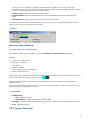
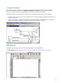
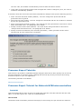
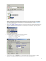
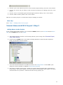
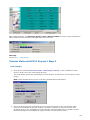
Select CPU as a target - if several CPUs are in the current project, it sets the CPU as target the CPU will appear on the Target CPU window and the code will be generated with the Project
options of active target.
The code design process checks the setting of the selected target. If the selected CPU doesn't
match a valid setting of the linker for the current CodeWarrior target, the code design process
displays the following dialog:
24
Following options are available:
¡
¡
¡
Leave the current setting - generate files to the current selected target without a change
of the linker
Second option automatically sets the linker setting according to the selected CPU,
including linker settings
Create new target - creates a new target and sets the linker and linker settings according
to the selected CPU. Generated files will be added into the new target. You can enter a
name of the target.
Click on the "OK" button to confirm the selection.
l
Rename CPU - allows you to give a project -specific name to the selected CPU
l
CPU peripherals names - opens the CPU peripheral´s names editor.
l
View Target CPU Package - opens the Target CPU window in Package view.
l
View Target CPU Block Diagram - opens the Target CPU window in Block Diagram view.
l
View CPU structure - displays the CPU structure schematic.
l
l
View Memory Map - displays the Memory map window. This window shows the CPU address.
Space and internal and external memory mapping.
Search in PDF documentation - displays the PDF Search window. The window allows a fulltext search in the original CPU manufacturer's documentation.
l
View source - displays the generated CPU module in the File editor.
l
View/edit events code - displays the generated CPU events module in the File editor.
l
View/edit main module - displays the generated main module in the File editor.
l
View linker file - displays the generated linker file (if it exists) in the File editor.
l
View makefile - displays the generated maker file (if it exists) in the File editor.
l
View MAP file - displays the MPA file in the File editor.
l
View list of methods - displays the list of methods.
l
Restore default template settings - restores default setting of the template.
l
Customize this bean template - saves the highlighted (chosen) CPU and its settings as a
template.
l
Remove CPU from project - removes the highlighted (chosen) CPU from the project.
l
Help - displays documentation.
Beans Local Menus
25
Beans folder local menu
This menu is opened by right-clicking on the Beans folder icon in Project Panel. Following commands
are available:
l
Expand/Collapse - expands/collapses one level of the folder's tree.
l
Expand all - completely expands the folder's tree.
l
Collapse all - completely collapses the folder's tree.
l
Change folder name - edits the subfolder name.
l
Delete folder - deletes the subfolder and all its contents.
l
Delete all beans - deletes all beans from the project.
l
Add bean(s) - invokes a dialog which allows the user to choose and add new beans to
project.
l
Add subfolder - creates a new subfolder.
l
Import Beans - Imports all beans from a file (project).
l
Export Beans - Exports selected beans including settings to the file.
l
Help - displays documentation.
Bean local menu
This menu is opened by clicking right mouse button on the icon of the bean from the beans folder of
the Project panel. Following commands are available:
l
Bean inspector - opens the Bean inspector of the bean. Detailed help concerning the Bean
Inspector items can be found in the bean's page of Processor Expert help.
l
Bean enabled - if checked, the selected bean is enabled (included in project).
l
Rename bean - allows you to give a project-specific name to the selected bean.
l
View source - displays the generated module of the bean in File editor.
l
View/edit events code - displays the generated events module of the bean in File editor.
l
l
l
Restore default template settings - restores default template settings. All old settings will be
lost.
Customize this bean template - saves the selected bean as a template
Disconnect bean from CPU - removes the link(s) between the bean and the associated CPU
peripheral(s) ( it clears the corresponding properties of the bean).
l
Remove bean from project - removes the selected bean from the current project.
l
Copy to clipboard - bean with it's settings is copied to the clipboard.
l
Help - displays documentation.
Methods and Events
This menu is opened by right-clicking on a method or event icon. It proposes a set of commands
concerning the selected method/event.
l
Enable/Disable - enables/disables the selected method in current project.
26
View source - shows generated method source. Available only after successful
code design.
l
method only:
l
event only:
l
Put invocation into editor - inserts invocation to the current line of the text editor.
l
Help - displays documentation.
Edit code - opens a selected event in editor. Available only after successful code
generation.
Documentations Local Menu
Documentations Folder local menu
This menu is opened by right-clicking on the Documentation folder icon in the Project Panel.
Following commands are available:
l
Add documentation file - add a new documentation file into project
l
New documentation
¡
Text file - creates a new text documentation file.
¡
HTML file - creates a new HTML documentation file.
l
Expand/Collapse - expands/collapses one level of the folder's tree.
l
Expand all - completely expands the folder's tree.
l
Collapse all - completely collapses the folder's tree.
l
Delete all documentation - deletes all the contents of the folder.
l
Help - displays documentation.
Documentation local menu
This menu is opened by clicking right mouse button on the documentation file from the
Documentations folder of the Project panel. Following commands are available:
l
View documentation - shows the document in the File Editor.
l
Edit documentation - edits the document in the File Editor.
l
Open in external viewer - uses the default shell editor to open the document.
l
Remove from project - removes the document from the project.
l
Help - displays documentation.
PESL Folder Local Menus
PESL folder local menu
This menu is opened by right-clicking on the PESL folder icon in the Project Panel. Following
commands are available:
l
Expand/Collapse - expands/collapses one level of the folder's tree.
l
Expand all - completely expands the folder's tree.
l
Collapse all - completely collapses the folder's tree.
l
PESL enabled - enables/disables use of the PESL (Processor Expert Support Library)
27
l
Help - displays documentation.
PESL local menu
This menu is opened by right-clicking on the PESL method.
Following commands are available:
l
Put invocation into editor - inserts invocation to the current line of the text editor.
l
Help - displays PESL documentation for the selected item.
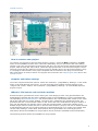
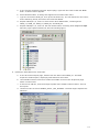
Bean Selector
Processor Expert | View | Bean Selector
Bean Selector shows supported beans including CPU beans and bean templates. It lets a user
select a desired bean or template and add it to the project.
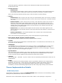
Two filters could be applied on the list. They could be switched on/off by clicking on two buttons on
the bottom bar.
l
l
all/CPU - If this filter is active, only the beans that could be used with the current target CPU
derivative are shown.
license - If active, only the beans with valid license are shown.
The Bean Selector contains the following two tabs allowing user to see list of the bean in two
modes:
l
l
Bean Categories - contains all available beans. The beans are sorted in a tree based on the
categories defined in the beans.
On Chip Peripherals - shows all beans available for the specific peripherals. All chip
peripherals, sorted by name, are listed in the appropriate CPU folder, depending on which
peripheral can be used. Current target CPU bean is displayed at the top (only if a target CPU
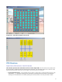
bean is selected).
There are three different icons of peripheral folders which depends on the usage of the
peripheral.
¡
If the peripheral is fully available, the folder is displayed by yellow
¡
If the peripheral is partially used, the folder is displayed by light blue
¡
The fully used peripheral is displayed by blue
The icon
"greyed"
icon.
icon.
icon.
means that there is an available license for the bean. If the icon is displayed as a
icon, it means that for the selected bean a valid license is not available.
The bean names are colored black and the bean template names are colored blue. By doubleclicking on the bean it is possible to insert the bean into the current project. The description of the
bean is shown in a hint.
The button Quick Help shows short information about function of the bean. The Quick Help is
displayed as a part of the Bean Selector window and is updated when user selects another bean in
the tree.
Folder local menu
The local menu is available by clicking the right mouse button on a folder.
l
Expand/Collapse - expands or collapses the folder
28
l
Expand all - expands the folder and all its subfolders
l
Collapse all - collapses the folder and all its subfolders
l
Help on Bean Selector- displays documentation for the Bean Selector.
Bean local menu
The local menu is available by clicking the right mouse button on a bean.
l
Add the bean to the current project - adds the bean to the current project.
l
Delete selected template- removes the selected template from the Bean Selector.
l
Help on Bean- displays bean documentation.
l
Help on Bean Selector- displays documentation for the Bean Selector.
Bean Selector local menu
The local menu is available by clicking right mouse button on the area inside the Bean Selector
window
l
l
Update - updates new beans and templates to the tree according to the appropriate category
in the Bean Selector window.
Help on Bean Selector - displays documentation for the Bean Selector.
Target CPU folder local menu
The local menu is available by clicking the right mouse button on the Target CPU folder in the On
Chip Peripheral mode.
l
l
CPU Inspector - opens the CPU's Bean inspector - Detailed help concerning the Bean
Inspector items can be found in the CPU's page of Processor Expert help (see Processor Expert
| Help | Supported CPUs and Compilers page).
Select CPU as Target - if several CPUs are in the current project, it sets the CPU as target.
The CPU will appear on the Target CPU window and the code will be generated with the CPU's
Project options.
l
Rename CPU - allows you to give a project-specific name to the selected CPU
l
CPU Peripherals Names - opens the CPU peripherals names editor.
l
View Target CPU Package - opens the Target CPU window in Package view.
l
View Target CPU Block Diagram - opens the Target CPU window in Block Diagram view.
l
View CPU Structure - displays the schematic CPU structure .
l
l
View Memory Map - displays the Memory map window. This window shows the CPU address.
Space and internal and external memory mapping.
Search in PDF Documentation - Displays the PDF Search window. The window allows a fulltext search in the original CPU manufacturer's documentation.
l
View Source - displays the generated CPU module in the File editor.
l
View/Edit Events Code - displays the generated CPU events module in the File editor.
l
View/Edit Main Module - displays the generated main module in the File editor.
l
View Linker File - displays the generated linker file (if it exists) in the File editor.
l
View Makefile - displays the generated maker file (if exists) in the File editor.
29
l
View MAP File - displays MPA file in the File editor.
l
View List of Methods - displays the list of methods.
l
Restore Default Template Settings - restores default setting of the template.
l
l
l
Customize this bean template - saves the highlighted (chosen) CPU and its settings as a
template.
Remove CPU from project - removes the highlighted (chosen) target CPU from the current
project.
Help - displays documentation.
Peripheral folder local menu
The local menu is available by clicking right mouse button on the peripheral in the On Chip
Peripheral mode.
l
Expand/Collapse - expands or collapses the folder
l
Expand All - expands the folder and all of its subfolders
l
Collapse All - collapses the folder and all of its subfolders
l
l
l
l
l
Show Peripheral Structure - opens the peripheral's structure view (see CPU structure ) - (it is
supported for I/O ports, timer's counters, serial ports. It is also supported for devices working
in several modes in the MCU block diagram. A list of represented devices for these modes is
displayed.
Rename Peripheral - allows the user to rename the selected peripheral. It is supported for I/O
ports and pins, watchdog and timers (counters, compare and capture registers, free running
devices), A/D converters and A/D channels, CAN, serial ports. See details for renaming
peripherals.
Show Peripheral Usage - shows which part of the peripheral is used by the application (visible
after code design). It is supported for I/O ports and pins, timers, A/D converters and A/D
channels, CAN, serial ports, watchdog, internal memories (EEPROM and FLASH). (see
Peripherals Usage Inspector ).
Show Peripheral Initialization - shows initialization values of all "control, status and data"
registers. It is supported for all devices displayed on CPU package. (see Peripherals
Initialization Inspector).
Search Related Info in CPU PDF Documentation displays the PDF Search window and finds
information about the peripheral in the appropriate CPU documentation. It is for possible to
search for any keyword in the CPU documentation based on the original manufacturer's CPU
manual. (This item is available on the package and on the CPU block only.)
l
View MCU Block Diagram - displays the CPU block diagram in the Target CPU window.
l
Help on Bean Selector - displays documentation on the Bean Selector
Picture
30
Inspector
Processor Expert | View | Bean Inspector
Inspector is universal tool, which allows to view and edit attributes of a Bean, Configuration or
Peripheral bean. Inspector can work in these modes depending on the type of inspected object.
l
l
l
Bean inspector - provides access to Properties, Methods, Events, and Comments for the
beans, arranged in a switchable pages. See details in chapter Bean inspector. Bean Inspector
for CPU bean offers additional Build options (if a target compiler is selected) and Used
peripherals pages.
Peripheral inspector - is very similar to the Bean inspector. Allows to setup Properties and
Comments of peripheral beans.
Configuration inspector - Provides access to settings of a configuration. See details in chapter
Configuration inspector.
Inspector window contains three columns:
l
l
l
Item names - items that are to be set are listed in the left column of the inspector. Groups of
items describing certain features may be collapsed/expanded by double clicking on the first line
of the group. By double clicking on a method or event item, you may open the File Editor at the
position of the corresponding method or event.
Selected settings - the settings of the items are made in the middle column, at the right of the
name. Timing settings may be made with the Timing dialog box that gets open when clicking on
. The "generate code"/"don't generate code" setting of methods and events determines
whether the implementation code for the corresponding method or event will be generated or
not (you may thus generate only the methods and events used by your application).
Setting status - the current setting or an error status may be reflected on the same line, in the
right column of the inspector.
Items that cause errors or warnings are written in pink.
View mode buttons
They are placed at the bottom of the window (Basic, Advanced, Expert). They allow user to switch
complexity of the view of the bean's items. See the chapter items Visibility for further details.
Items Visibility
Processor Expert supports selectable visibility of bean items. Each item is assigned a predefined
level of visibility. Higher visibility level means that items with this level are more special and rarely
used than the others with the lower visibility level. Bean Inspector displays only items on and
below the selected level. It could help especially beginners to set only basic properties at first and
do optimization and improvements using advanced and expert properties or events later. There are
three visibility levels:
31
l
l
l
Basic view - key items that have no default value and must be set for each bean, for example
peripherals . To view these items select command Inspector | Items Visibility | Basic view.
Advanced view - key items that should be set or that are usually set (including necessary items)
To view these items select command Inspector | Items Visibility | Advanced view.
Expert view- maximum visibility level. All items that can be changed including rarely used
items. To view these items select command Inspector | Items Visibility | Expert view.
See also the main page of the Bean Inspector chapter for more information how to switch view
modes.
Note: If an error occurred in a property with a higher visibility level than the level currently selected, this
error nevertheless will be displayed.
Bean Inspector
Bean inspector is one variant of the Inspector window. It allows to setup Properties, Methods, and
Events for the given bean. Use command Help | Help on Bean from Bean Inspector menu to see
documentation for currently opened bean.
The Comments page allows the user to write any comment about the bean or setting used.
The Build options page provides access to the settings of the compiler (or debugger) selected in
Project Options. These settings are different for each compiler (or debugger), and are reset every
time the compiler (or debugger) is changed.
The Used page shows list of the CPU bean resources. User can also manually block individual
resources for using them in Processor Expert.
The page consists of the three columns:
l
l
First shows the name of the resource. Resources are in groups according to which device they
belong to.
Second column allows user to reserve resource (for example pin) for external module. Click on
icon to reserve/free a resource. Reserved resource could not be use in Processor expert
any more.
l
Third column shows the current status of the resource and the name of the bean which uses it
(if the resource is already used).
Menu
The following items are available:
l
Bean
¡
Template
n
n
n
Restore default template settings - restores settings of the template.
Customize this bean template. - invokes template editor. See details on Bean
Templates here.
Active template - Shows list of currently available templates for the bean with
currently active template selected.
¡
Change bean icon - allows the user change the bean icon.
¡
Autoconnect - auto connects the bean to the CPU.
¡
Disconnect - disconnects the bean from the CPU.
l
Items Visibility - see the chapter Items Visibility for more information about view modes.
l
Help
¡
Help on Selected tab - displays documentation for the current tab.
¡
Help on Inspector - displays Bean Inspector documentation.
32
l
¡
Help on Bean - displays documentation for the selected bean.
¡
Embedded Beans Page - displays Embedded Beans documentation.
Peripheral initialization button - This button will show the Peripheral initialization inspector. If
the button is pushed, the peripheral initialization inspector window is be glued to the Bean
inspector window.
Picture
Dialog Box for Timing Settings
The Timing dialog box provides a user-friendly interface for the settings of bean timing features.
When clicking on the
button of a timing item in the Bean Inspector, the timing dialog box is
displayed.
Before you start to edit bean timing you should set:
l
Target CPU in the Project Panel
l
Used peripherals in the bean's properties
l
Requested prescaler in the bean's properties, if supported
l
Supported speed modes in the bean's properties
Options
Upper left panel
Runtime setting
determines how the timing setting can be modified in runtime.
Runtime setting is not supported in the BASIC view mode.
Runtime setting type:
l
l
l
fixed value: it will not be possible to change the timing setting of the bean in runtime.
from a list of values: it will be possible to select a new value among predetermined values
from the list (use the Add and Delete buttons to control number of values in the list). Each value
in the list defines a mode and you can switch between them using method Set???Mode(name of
the method depends on the bean) .
from interval: it will be possible to select a new value within a predetermined interval.
This Runtime setting type requires runtime calculations to change time setting of the bean. The
runtime setting type may not be supported on small microcontrollers.
33
The modification of timing settings at runtime is done using Bean methods. Some of them will be
enabled only if you select corresponding Runtime Setting Type.
Upper right panel
Value
currently edited time: initialization value, value in any mode from the list or limit of the interval.
l
l
Requested value: write here the value you wish to set and select the unit in the Units list box.
If you select the With value check- box, the value is recomputed at every unit change.
Tip: Double- click on the requested value to see all supported values close to the selected one.
It is possible to specify desired precision of the timer settings by using one of these settings
(which one is used depends on the type of the timing) :
¡
¡
l
l
Error allowed - This field allows to specify the tolerated difference between real timing
and the requested value. The % check-box allows user to set the degree of precision as a
percentage of the requested value.
Min. resolution - Minimal resolution of timer ticks. This setting is used for setting interval or
capture bean timing. Allows user to specify maximal acceptable length of one tick of the
timer. The % check-box (if it is present) allows user to set the degree of precision as a
percentage of the initial value.
Adjusted value, Prescaler, Error: Shows the real value computed from chosen on-chip
peripheral settings, selected Prescaler value and the difference between the value selected by
the user and the real value.
Status line below: displays status of the timing setting. If the requirements are impossible to
meet, a red error message is displayed.
Bottom panel
Possible settings
values supported by the Target CPU for the selected peripheral.
l
l
l
l
Closest values: supported time values that are the closest to the requested value.
Possible in high (and/or low, slow) speed mode: all correct settings in high/low/slow speed
mode.
Tip: Click on any value to see all supported values close to the selected one.
Overclocked(check-box below for information only) : if checked, the bean supports extension of the
hardware timing by the 8-bit software counter.
Intersection of speed modes(check-box below visible only in EXPERT view mode) if selected the
Possible settings box contains only values which are available in all speed modes supported by
the bean.
Note: Speed modes and related settings are supported only in EXPERT view mode.
Prescaler
Is possible to set a requested prescaler value in several beans. You can choose "Autoselect" for
automatic selection (default value).
Some peripherals support internal prescalers - any other peripheral can divide its clock. You can set
this special prescalers in the bean properties - item Prescaler (if supported). The internal prescaler
are not used by autoselection. Internal prescaler peripherals can be selected in other beans as
internal prescaler but cannot be used as a peripheral (as an interrupt source).
34
Syntax for the Setting of Timing Features in the Bean
Inspector
In timing data fields, it is necessary to type not only a value (integer or real number) but also the
unit of that value.
Supported units
l
microseconds - the value must be followed by us
l
milliseconds - the value must be followed by ms
l
seconds - the value must be followed by s
l
CPU ticks - the value must be followed by ticks
l
Hertz - the value must be followed by Hz
l
kilohertz - the value must be followed by kHz
l
megahertz - the value must be followed by MHz
l
bit/second - the value must be followed by bits
l
kbit/second - the value must be followed by kbits
Example
If you want to specify 100 milliseconds, enter 100 ms
Defaut Values for Properties
Some properties can have a global default value. Once you enter the value for the property and
you confirm that it will be the default value for the property then it will be used automatically in the
future.
If you open a project with different settings or change the value of the property in the Bean
Inspector, a Processor Expert automatically offers the following options:
l
l
l
l
l
use new value as default value - remember the newly entered (or just loaded) value as the
new default value (change default value),
use my default value - cancel changes (discard loaded value) and use previous default value,
use new value and do not change default value - use the newly entered (or just loaded)
value and do not change the default value,
do not use default value for this item - permanent settings, never use default value for this
property,
use always default value for this item during project loading - permanent settings, do not
display this dialog and always use the default value during project loading and template
creation.
35
Note: This item is accessible only during project loading.
Permanent settings or default values can be removed in Environment Options.
Picture
Version Specific Items
The Version specific items (properties, methods and events) are displayed only for some CPU
derivatives.
The version specific item is displayed as a highlighted field in the first column of the Bean Inspector.
See the following picture. There are two items with this feature:
Some items of the bean are displayed as mirrored items from the CPU bean. The item is displayed
only if the bean property has any relation to the bean setting. The item setting is global: this
means that it is possible to set the item in any bean where the item is available and the setting is
used for all appropriate beans. Display of the mirrored items depends on the setting of the bean.
The information about the item is displayed in the item hint.
See the picture below:
Configuration inspector
Configuration inspector is a variant of a Inspector Window. It could be invoked from configurations
local menu in the Project Panel. Click on the configuration with the right button and choose
Configuration inspector.
Optimization settings
36
The following setting should be used when the code is already well debugged. These settings could
increase speed of the code, but the generated code is less protected for the unexpected situations
and finding errors could be more difficult.
l
l
l
Ignore range checking - This option can disable generation of the code, that provides testing
for parameter range. If the option is set to "yes", methods do not return error code
ERR_VALUE neither ERR_RANGE. If the method is called with incorrect parameter, it may not
work correctly.
Ignore enable test - This option can disable generation of the code, that provides testing if the
bean/peripheral is internally enabled or not. If the option is set to "yes", methods do not
return error code ERR_DISABLED neither ERR_ENABLED. If the method is called in unsupported
mode, it may not work correctly.
Ignore speed mode test - This option can disable generation of the code, that provides a
testing, if the bean is internally supported in the selected speed mode. If the option is set to
"yes", methods do not return error code ERR_SPEED. If the method is called in the speed mode
when the bean is not supported, it may not work correctly.
Error Window
Processor Expert | View | Error window
This window displays errors, warnings, and hints that are found during:
l
project checking
l
code generation,
l
running of an external tool.
Some errors are found right after inconsistent or incorrect data have been entered, others during
the code generation of a project. The single messages mention the bean where the error was
found. If an error concerns two beans (where conflict results for example from using the same onchip peripheral), the error will be attributed to both beans.
If you click the right mouse button, a local menu appears that allows you to delete either tools or
code generation errors, warnings and hints in order to improve the readability of the Error window.
Picture
Local Menu
The local menu contains the following items:
l
l
l
Delete all tool errors, warnings and hits - removes all tool errors, warnings and hits listed in
the Error window
Delete all code generation errors, warnings and hits - removes all code design errors,
warnings and hits listed in the Error window
Help - display documentation
37
Target CPU window
Processor Expert | View | Target CPU Package
Processor Expert | View | Target CPU Block Diagram
Processor Expert | View | Target CPU Structure
This window displays selected target CPU with its peripherals and pins (possible data directions
of single pins are indicated by blue arrows on the CPU package when a bean uses these pins).
Several display modes are supported. It is possible to switch the display mode by pushing buttons
in the left side menu of the window.
Some signals and peripherals cannot be used by the user because they are allocated by the special
devices such as power signals, external or data bus. Special devices are indicated by a special blue
icons, for example
. The allocation of peripherals by special devices could be influenced by CPU
properties.
The meanings of the buttons on the left side are:
Rotates CPU - rotate the CPU 90 degrees to the right.
l
l
Show user names on CPU package - switches the pins' and peripherals' default names
(from catalog) for user-defined names.
Print CPU on printer - prints the CPU picture.
l
l
l
l
l
l
Always show bean icons - CPU package's size may be reduced, provided bean icons are
still displayed.
Always show internal peripheral devices - CPU package's size may be reduced, provided
on-chip peripheral devices are still displayed.
Show CPU package and peripheral - switches to a realistic view of the CPU package and
peripheral.
Show BGA CPU package - This option is allowed only for CPUs with grid-array pins layout.
Pins hidden by package are shown and the peripherals are hidden.
Show CPU block diagram - switches to a view of theCPU block diagram based on the
documentation of the MCU manufacturer.
Pins
The following information about each pin is displayed on the CPU picture:
(all pins are displayed only on the CPU package)
l
pin name (default or user-defined)
l
icon of a bean that uses (allocates) the pin
l
direction of the pin (input, output, or input/output) symbolized by blue arrows, if a bean is
connected
Pin hint contains:
l
number of the pin (on package)
l
both names (default and user-defined)
l
owner of the pin (bean that allocates it)
l
short pin description from CPU database
Bean icon hint contains:
38
l
bean name
l
bean type
l
bean description
Mouse operations:
l
clicking on a bean icon selects the bean in Project panel
l
double clicking on a bean icon opens its Bean Inspector
l
right clicking on an icon opens the Bean local menu
l
right clicking on a pin opens the Periphery local menu
Pin names are shortened and written either from left to right or from up to down.
On-chip peripherals
The following information about each on-chip peripheral is displayed on the CPU package:
l
peripheral device name (default or user-defined)
l
icon of the bean that uses (allocates) the peripheral device
Peripheral device hint contains:
l
peripheral device name
l
owner of the pin (bean that allocates it)
l
short peripheral device description
Hint on icon contains:
l
bean name
l
bean type
l
bean description
If a peripheral is shared by several beans (for example: several beans may use single pins of the
same port), an
icon is displayed.
Mouse operations:
l
clicking on an icon selects the bean in Project panel
l
double clicking on a bean icon opens its Bean Inspector
l
double clicking on a resource item opens the simple item structure view (see CPU Structure).
l
l
l
l
double clicking on an
icon opens a selection menu with all the beans that use single parts of
the peripheral. Selecting one bean opens it in the Bean Inspector.
right clicking on a bean icon opens the Bean local menu.
right clicking on an
icon opens selection menu with all the beans that use single parts of the
peripheral. Selecting one bean opens the Bean local menu.
right clicking everywhere else opens the Peripheral local menu
Note for peripherals working in several modes:
Some peripherals work in several modes and these peripherals can be represented by a several
devices in the CPU databases. For example, the device "TimerX_PPG" and "TimerX_PWM"
represents TimerX in PPG and in PWM mode. These devices can be displayed on the CPU package,
but they are also represented as a single block in the MCU block diagram.
39
Peripheral/Pin Local Menu
The following items are available in the local menu:
l
l
l
l
l
l
l
Show peripheral structure - opens the peripheral's structure view (see CPU structure ) - (it is
supported for I/O ports, timer's counters, serial ports. This option is also supported for devices
working in several modes in the MCU block diagram. A list of represented devices for these
modes is displayed.
Rename peripheral - allows you to rename the selected peripheral. It is supported for I/O
ports and pins, watchdog and timers (counters, compare and capture registers, free running
devices), A/D converters and A/D channels, CAN, serial ports.
Show peripheral usage - shows which part of the peripheral is used by the application (visible
after code generation). This option is supported for I/O ports and pins, timers, A/D converters
and A/D channels, CAN, serial ports, watchdog, internal memories (EEPROM and FLASH). (see
Peripherals Usage Inspector).
Show peripheral initialization - shows initialization values of all "control, status and data"
registers. This option is supported for all devices displayed on a CPU package. (see Peripherals
Initialization Inspector).
Add bean - adds a bean to the appropriate peripheral: all available beans for the selected
peripheral are listed. It is possible to add only beans which are applicable for the peripheral. It
means that is possible to add the bean only if the peripheral is not already allocated to
another bean or beans. The beans which cannot be added to the peripheral are grayed in the
local menu as unavailable. This option is supported for all devices displayed on CPU package.
Search related info in MCU PDF documentation displays PDF Search window and finds the
information about the peripheral in the appropriate CPU documentation. It is also possible to
search for any keyword in the CPU documentation based on the original manufacturer's CPU
manual. (This item is available on the package and on the CPU block only.)
Help on Target CPU Window - displays help for the current window
Pictures
Target CPU - CPU and package view mode
Target CPU - BGA CPU package view mode
40
Target CPU - MCU block diagram view mode
CPU Structure
Project Panel | CPU local menu | View CPU structure
This window presents the schematic structure of the target CPU. The CPU devices are ordered in
a tree structure, starting with the following main branches. The prescaler values are values in high
speed mode and these values are set-up after reset if the device is enabled.
l
SystemClockPrescaler - time related devices (timers, watch-dogs, communication devices, A/D
converters, ...). The actual setting of the prescaler is displayed in this window, and possible
settings are indicated as a hint when putting the mouse pointer over the prescaler's name.
41
l
I/O Ports - directly usable I/O ports of various widths (1, 8, 16, 32, ... bits).
l
External Interrupts - external hardware interrupts.
l
DMA channels - DMA channels provided by the hardware.
You may expand and collapse the tree's branches by clicking on the plus "+" or minus "-" signs,
respectively.
Picture
Resource Meter
Processor Expert | View | Resource Meter
The Resource Meter shows the current status of a chip resource usage (or availability).
Note that if a peripheral is allocated, all its parts are reserved. For example if you use the 8-bit I/O
port, all the I/O pins of the port are allocated and it is not possible to use them in other beans.
l
l
l
Pins usage meter shows pins' usage. In general, there are always some pins used, such as
the power supply pin.
Port usage meter shows ports' usage. A port is considered allocated if a part of it is used, or if
its pins are allocated to another device.
Compare/Reload meter shows the allocation of the timer compare registers (depending on
42
CPU type). If it is possible to combine several smaller registers into one large, then the
allocation of one of the smaller ones means allocation of the large one and the allocation of the
large one means allocation of the two smaller ones.
l
l
l
Capture regs shows timer capture registers usage.
Communication shows the allocation of the serial communication channels (including also
CAN).
A/D channels shows the allocation of the A/D converter channels.
By placing the mouse over a resource meter field, you may get a hint that provides details about
which resources are used concerning this field.
Picture
Memory Map Window
Processor Expert | View | Memory Map
This window shows the CPU address space and internal and external memory mapping.
Legend:
l
white: non-usable space
l
dark blue: I/O space
l
blue: RAM
l
light blue: ROM
l
cyan: FLASH memory or EEPROM
l
black: external memory
If the project is successfully compiled and if the debugger is started, black crossed lines are applied
to the zones which are used by compiler (e.g.
).
Note: memory allocation is supported only for some compilers, that produces these information in
readable format.
If you move the mouse pointer to any part of the CPU address space, a detailed description of the
chosen part will be displayed in the hint.
Local Menu
l
Display Mode
¡
Full - displays all items.
¡
Only Memory - displays only Flash, RAM and ROM.
l
Summary - displays window with summary of memory usage (percentage and absolute view).
l
Help - shows this page.
CPU Types Overview
43
Processor Expert | View | CPU Types Overview
The CPU Types Overview window (Menu - View) provides an overview of the database's CPUs.
The overview is given in the form of a tree structure going from CPU producers to CPU families and
finally CPU variants. The picture of the selected CPU variant is displayed on the Target CPU window.
If you click the right mouse button on the window, a local menu appears:
l
l
Add CPU into project - adds the selected CPU into the project (it will appear in the Project
Panel).
Expand/Collapse - expands/collapses the next level of the tree structure or packs the current
one.
l
Expand all - expands the entire tree structure.
l
Collapse all - expands the entire tree structure.
l
Help - opens the help page concerning this window.
Picture
CPU Parameters Overview
Processor Expert | View | CPU Parameters Overview
You may get the technical features of a CPU by selecting the CPU Parameters Overview item of
the View menu. The complete database then appears together with a query window. By specifying
requirements on technical features, you may filter the database in order to display only relevant
CPUs. If you press OK, you will get the list of CPUs that meet your requirements. If you press All,
all the CPUs supported by your version of Processor Expert will be listed.
Picture 1
44
Description
The CPU Parameters Overview windows displays the list of CPUs, including their technical
features:
l
CPU type - CPU type
l
Producer - CPU producer
l
Family - CPU family
l
Clock - CPU xtal clock
l
Dual clock - CPU dual clock
l
Temperature - CPU operating temperature
l
#pins - number of pins on CPU package
l
#IO ports - number of I/O ports and I/O pins
l
#timers - number of timers, compares and captures
l
#A/D - number of A/D channels
l
#serial - number of asynchro/synchro serial channels
l
Watchdog - on-chip watchdog
l
RAM - on-chip RAM size
l
ROM - on-chip ROM size
l
EPROM - on-chip EPROM size
l
FLASH - on-chip FLASH size
l
OTP - on-chip OTP size
l
Power supply - power supply voltage
l
Comment - comment
l
Storage - CPU storage temperature
l
Special - Special features and devices
If you right- click on the window, a menu appears allowing you to add the selected CPU to the
current project or to refine your previous query.
Picture 2
45
List of Installed Beans with Additional Information
Processor Expert | View | Installed Beans Overview
This window contains information about installed beans in the current version of Processor Expert:
l
BEANS
All installed beans including CPUs and user-created beans are listed in the report.
See menu | View | Bean Type for bean type selection.
l
Bean Info
This information is also displayed as a hint on the bean.
¡
bean description
¡
file format and access (encrypted, full source, compressed)
¡
author of the bean
¡
version
l
Drivers
l
Driver Info
This information is also displayed as a hint on the driver.
l
¡
Status - file format and access (encrypted, full source, compressed)
¡
Author of the driver
¡
Current version of the driver
¡
Init. date - date of creation
¡
Last modification - date of last modification
Typical Settings
You can open a selected project or add beans from a selected project into the current project.
Use local menu or command from menu Projects. Selected project can also be opened by a
double-click.
A description of the project is available as a hint on the project name.
Note: If all fields in the column are empty, the projects with typical beans were not distributed with
your version of Processor Expert.
The contents of the window can be configured using commands in menu View. It is posssible to
view this window also in HTML format using command View | As HTML .
Menu
l
View
¡
¡
¡
Bean Type
n
all - displays all beans.
n
Beans only - hides CPU beans.
n
CPUs only - displays CPU beans only.
Bean Info
n
all - displays information about the bean.
n
basic - displays basic information about the bean only.
n
none - hides information about the bean.
Drivers
n
all - displays all bean's drivers.
n
none - hides all drivers.
n
subdirectories - displays drivers from a selected subdirectory.
46
¡
¡
Driver Info
n
all - displays information about drivers.
n
basic - displays basic information about the bean's driver only.
n
none - hides information about drivers.
Implementation
n
n
n
¡
¡
display all - shows all beans.
Hide beans without any selected driver - shows only beans which contain the
selected driver.
Hide beans with any selected driver - shows only beans which do not contain any
selected driver.
Bean Settings
n
all - displays a list of projects with typical bean settings.
n
none - hides the list of projects.
n
subdirectories - displays projects only from the selected subdirectory.
As HTML - display this table in default HTML browser.
Temporary HTML file will be removed from the disk after closing Processor Expert.
l
Project
This submenu is available only when project with typical bean settings is selected.
¡
¡
l
Open Selected Project - opens currently selected project with typical bean settings.
Add beans from selected into current project- adds all beans except CPUs from currently
selected project into current project.
Help
¡
Help on Bean- displays help for currently selected bean (except CPU beans).
¡
Help on this Window - displays this page.
Picture
Peripherals Usage Inspector
Processor Expert | View | Peripherals Usage Inspector
The Peripheral Usage Inspector shows the current status of on-chip peripherals usage in detail.
The names of the beans using peripherals appear in the third column, next to the corresponding
peripheral names. When the mouse is over a peripheral name, a short description of the peripheral
appears as a hint.
Note that if a peripheral is allocated, all its parts are reserved. For example if you use the 8-bit I/O
port, all the I/O pins of the port are allocated and it is not possible to use them in other beans.
47
The following items are available:
l
l
I/O page shows I/O pins' and ports' usage. If a pin/port is allocated to a bean, the I/O
properties of the bean are displayed below the pin/port's name (unless all the pins of a port
are used by one bean, in which case, the properties appear under the name of the allocated
pins).
Interrupts page shows interrupt vectors usage. If an interrupt vector is allocated to a bean,
the bean's name and the interrupt priority are displayed below the vector's name.
l
Timers page shows the allocation of the timers.
l
Channels page shows A/D, CAN and serial channels usage.
Menu
l
View
¡
¡
l
Sort registers by address - If this item is checked, registers are sorted in list by their
address. Otherwise they are sorted by name.
Group registers - will show groups of numbered registers with the same name as
expandable folders. The name of each folder is the same as the name of registers with the
numbers replaced by 'xx'.
¡
Expand all - expands the folder and all its subfolders.
¡
Collapse all - collapses the folder and all its subfolders.
Help
¡
Help - displays documentation.
Picture
Peripherals Initialization Inspector
Processor Expert | View | Peripherals Initialization Inspector
48
The Peripheral Initialization Inspector shows overview of peripheral initialization settings for the
current CPU. It displays initialization values of all control, status and data registers of selected
peripheral including single bits. User can also see peripheral schematic diagram. Peripheral
Initialization Inspector can be invoked from the View menu or from Target CPU window.
The initialization information reflects:
l
l
CPU default settings - when the peripheral is not utilized by Embedded Bean
Embedded Bean settings - when the peripheral is utilized by the Embedded Bean and the bean
settings are correct. Peripheral Inspector shows initialization as required by Beans settings.
User can watch reflections of user settings to Embedded Bean Properties directly in CPU peripheral
registers and bits.
Registers
There is displayed a value in the middle column, which will be written into the register or bit by the
generated code during the initialization process of the application. In case the peripheral is
allocated by a bean and the setting of the bean is incorrect, then the initialization values are not
displayed in the Peripheral Initialization Inspector. Instead, a value of the register (or bit) after
reset is displayed in the right column.
The values of the registers can be displayed in hexadecimal, decimal or in binary form. In case the
value of the register (or bit) is not defined, an interrogation mark "?" is displayed instead of the
value. In this case it is possible to display the value of the register in binary form only.
Screenshot of registers list in Peripheral Initialization Inspector:
Menu
l
View
¡
¡
l
Sort registers by address - If this item is checked, registers are sorted in list by their
address. Otherwise they are sorted by name.
Group registers - will show groups of numbered registers with the same name as
expandable folders. The name of each folder is the same as the name of registers with the
numbers replaced by 'xx'.
¡
Expand all - expands the folder and all its subfolders.
¡
Collapse all - collapses the folder and all its subfolders.
Help
¡
Help - displays documentation.
49
Peripheral schematic
It is possible to switch peripheral initialization window style between register list, peripheral
schematic and both of them using registers, schematic and both buttons. Schematic and both
buttons are present only when the schematic for the current peripheral is provided.
Schematic diagram of the peripheral contains blue-highlighted names of the control registers.
l
l
If user places mouse coursor on the register name, the hint containing register description and
address is shown.
When user clicks the register name with the left mouse button, new dialog window containing
detailed information (including initialization value) for the register is shown.
PDF Search
Processor Expert | Help | Search in PDF Documentation of the Target CPU
The PDF Search window allows the user to quickly browse PDF documentation for an CPU.
50
Window Consists of Three Panels:
l
l
l
The top panel with tab-control allows a user to select a mode of operation. This panel also
contains a combo or input box for specifying the subject of the search.
On the left side of the widow is a narrow panel containing as a result of search a list of the
pages containing the required information. Clicking on numbers in this listing invokes the
appropriate page in the Adobe Acrobat Reader panel.
Unfortunately Acrobat Reader does not permit highlighting of any text results found on the
page. You may find on the page using the Acrobat Reader "Find" function (see Acrobat Reader
toolbar).
The Acrobat Reader panel shows PDF file content. This panel has it ´s is own toolbar which
allows you to browse within the PDF file. This panel has also an internal Find function, which is
useful for locating searched phrase on the page. Using the toolbar you can print, move, and
zoom in or out on the document. More documentation about controlling the Acrobat Reader
plug-in can be found in Adobe Acrobat Reader documentation.
Three Modes of Searching in PDF Files:
l
l
l
The Peripherals mode allows users to find documentation for a selected on-chip device. Just
pick a peripheral for which you would like to find information. The listing shows the best
matches first.
Basic search mode - This is the easy way to find strings in text. Enter a searched word or it's
part in the input box and press Search.
Advanced search mode - This mode allows full control of the search process. Users can use
the power of regular expressions and switch on case sensitivity. The results are also displayed
in a list in the left panel. The syntax of regular expressions is a subset of commonly used Perl
regular expressions. You can fine more info on the Syntax of Regular Expressions page.
Our search technology uses the PdfToText program included in XPDF package. This package must
be installed in a subdirectory named XPDF. The PDF documents are being converted to the text
form in the background and stored in your TEMP folder. This conversion is executed only once for
each PDF file. The conversion may take a moment: please wait until it is finished
It is possible to find more information about XPDF on www.foolabs.com.
The configuration for the execution of the program PDFTOTEXT.EXE must be included in the
Processor Expert Tools.
The Acrobat Reader must be installed on your computer as well.
The PDF Search feature was tested with Acrobat Reader 5.0.
Regular Expressions
Regular Expressions are a widely-used method of specifying patterns of text to search for. Special
metacharacters allow the user to specify, for instance, that a particular string the user is looking for
occurs at the beginning or end of a line, or contains n recurrences of a certain character.
Simple Matches
Any single character matches itself, unless it is a metacharacter with a special meaning as
described below.
A series of characters matches that series of characters in the target string, so the pattern "bluh"
would match "bluh'' in the target string.
You can cause characters that normally function as metacharacters or escape sequences to be
interpreted literally by 'escaping' them by preceding them with a backslash "\", for instance:
51
metacharacter "^" matches the beginning of a string, but "\^" match character "^", "\\" match "\"
and so on.
Examples:
foobar
\^FooBarPtr
matches string 'foobar'
matches '^FooBarPtr'
Escape Sequences
Characters may be specified using an escape sequence syntax much like that used in C and Perl:
"\n'' matches a newline, "\t'' a tab, etc. More generally, \xnn, where nn is a string of hexadecimal
digits, matches the character whose ASCII value is nn. If You need wide (Unicode) character code,
You can use '\x{nnnn}', where 'nnnn' - one or more hexadecimal digits.
\xnn
char with hex code nn
\x{nnnn} char with hex code nnnn
(one byte for plain text and two bytes for Unicode)
\t
tab (HT/TAB), same as \x09
\n
newline (NL), same as \x0a
\r
car.return (CR), same as \x0d
\f
form feed (FF), same as \x0c
\a
alarm (bell) (BEL), same as \x07
\e
escape (ESC), same as \x1b
Examples:
foo\x20bar
matches 'foo bar'
(note space in the middle)
\tfoobar
matches 'foobar' predefined by tab
Character Classes
You can specify a character class, by enclosing a list of characters in straight brackets [], which will
match any one character from the list.
If the first character after the "['' is "^'', the class matches any character not in the list.
Examples:
foob[aeiou]r
finds strings 'foobar', 'foober' etc.
but not 'foobbr', 'foobcr' etc.
foob[^aeiou]r find strings 'foobbr', 'foobcr' etc.
but not 'foobar', 'foober' etc.
Within a list, the "-'' character is used to specify a range, so that a-z represents all characters
between "a'' and "z'', inclusive.
If you want "-'' itself to be a member of a class, put it at the start or end of the list, or escape it
with a backslash. If you want ']' you may place it at the start of list or escape it with a backslash.
Examples:
[-az]
[az-]
[a\-z]
[a-z]
matches 'a', 'z' and '-'
matches 'a', 'z' and '-'
matches 'a', 'z' and '-'
matches all twenty six small
52
[\n-\x0D]
[\d-t]
[]-a]
characters from 'a' to 'z'
matches any of #10,#11,#12,#13.
matches any digit, '-' or 't'.
matches any char from ']'..'a'.
Metacharacters
Metacharacters are special characters which are the essence of Regular Expressions. There are
different types of metacharacters, as described below.
Metacharacters - line separators
^
$
.
start of line
end of line
any character in line
Examples:
^foobar
foobar$
^foobar$
foob.r
matches string 'foobar' only if it's
at the beginning of the line
matches string 'foobar' only if it's
at the end of the line
matches string 'foobar' only if it's
the only string in the line
matches strings like 'foobar', 'foobbr',
'foob1r' and so on
Metacharacters - predefined classes
\w
\W
\d
\D
\s
\S
an alphanumeric character (including "_")
a nonalphanumeric
a numeric character
a non-numeric
any space (same as [ \t\n\r\f])
a non space
You may use \w, \d and \s within custom character classes.
Examples:
foob\dr
matches strings like 'foob1r', ''foob6r'
and so on but not 'foobar', 'foobbr' and so on
foob[\w\s]r matches strings like 'foobar', 'foob r', 'foobbr'
and so on but not 'foob1r', 'foob=r' and so on
Metacharacters - word boundaries
\b
\B
Match a word boundary
Match a non-(word boundary)
A word boundary (\b) is a spot between two characters that has a \w on one side of it and a \W on
the other side of it (in either order), counting the imaginary characters off the beginning and end of
the string as matching a \W.
53
Metacharacters - Iterators
Any item of a regular expression may be followed by another type of metacharacters - iterators.
Using this metacharacters you can specify a number of occurrences of a previous character,
metacharacter or subexpression.
*
+
?
zero or more, similar to {0,}
one or more, similar to {1,}
zero or one, similar to {0,1}
{n}
{n,}
{n,m}
exactly n times
at least n times
at least n but not more than m times
So, digits in curly brackets of the form {n,m}, specify the minimum number of times to match the
item n and the maximum m. The form {n} is equivalent to {n,n} and matches exactly n times. The
form {n,} matches n or more times. There is no limit to the size of n or m, but large numbers will
chew up more memory and slow down regular expressions execution.
If a curly bracket occurs in any other context, it is treated as a regular character.
Examples:
foob.*r
matches strings like 'foobar',
'foobalkjdflkj9r' and 'foobr'
foob.+r
matches strings like 'foobar',
'foobalkjdflkj9r' but not 'foobr'
foob.?r
matches strings like 'foobar', 'foobbr'
and 'foobr' but not 'foobalkj9r'
fooba{2}r
matches the string 'foobaar'
fooba{2,}r matches strings like 'foobaar', 'foobaaar',
'foobaaaar' etc.
fooba{2,3}r matches strings like 'foobaar', or 'foobaaar'
but not 'foobaaaar'
Metacharacters - Alternatives
You can specify a series of alternatives for a pattern using "|'' to separate them , so that fee|fie|foe
will match any of "fee'', "fie'', or "foe'' in the target string (as would f(e|i|o)e). The first alternative
includes everything from the last pattern delimiter ("('', "['', or the beginning of the pattern) up to
the first "|'', and the last alternative contains everything from the last "|'' to the next pattern
delimiter. For this reason, it's a common practice to include alternatives in parentheses to minimize
confusion about where they start and end.
Alternatives are tried from left to right, so the first alternative found for which the entire expression
matches, is the one that is chosen. This means that alternatives are not necessarily greedy. For
example: when matching foo|foot against "barefoot'', only the "foo'' part will match, as that is the
first alternative tried, and it successfully matches the target string. (This might not seem important,
but it is important when you are capturing matched text using parentheses.)
Also remember that "|'' is interpreted as a literal within square brackets, so if you write [fee|fie|foe]
You're really only matching [feio|].
Examples:
foo(bar|foo)
matches strings 'foobar' or 'foofoo'.
Metacharacters - Subexpressions
54
The bracketing construct ( ... ) may also be used for defining regular expression subexpressions.
Subexpressions are numbered based on the left to right order of their opening parenthesis. The
first subexpression has the number '1'.
Examples:
(foobar){8,10} matches strings which contain
8, 9 or 10 instances of the 'foobar'
foob([0-9]|a+)r matches 'foob0r', 'foob1r' ,
'foobar', 'foobaar', 'foobaar' etc.
Metacharacters - Backreferences
Metacharacters \1 through \9 are interpreted as backreferences.
\ matches previously matched subexpression #.
Examples:
(.)\1+
matches 'aaaa' and 'cc'.
(.+)\1+
also match 'abab' and '123123'
(['"]?)(\d+)\1 matches '"13" (in double quotes), or '4'
(in single quotes) or 77 (without quotes)etc
Application design
This chapter should help user to design application using Processor Expert and embedded beans.
You will find here recommendations and solutions helping you write and optimize a code effectively
and properly.
In the section Quick start you will find how to make your first Code Design.
The following subchapters explains
l
Embedded beans
l
CPU beans
l
Predefined symbols
l
Typical usage of beans in user code
l
Details about beans implementation
l
Configurations
l
Bean checking
l
Priorities
l
Bean templates
l
Inheritance of beans
l
Pin sharing
l
Code Design
l
Code Optimizations
l
Embedded Beans Optimizations
l
User changes in generated code
Quick Start - Processor Expert Plug-in for CodeWarrior
How To Get Started Quickly
55
Step 1 - Open an example
You may start learning Processor Expert by opening one of the available examples. All examples
are stored in the Projects directory - {CodeWarrior}\bin\plugins\support\ProcessorExpert\Projects.
You can also try one of our tutorials.
To open an example select command CodeWarrior main menu | File | Open ... or use the Open icon
on the toolbar. Select desired project in the Projects directory (see path above). Processor Expert
will start and open the project.
Step 2 - Code design
After opening an example, you need to code design the project to obtain all sources. Select
command CodeWarrior Main Menu | Processor Expert | Code Design 'Project Name'. After the code
generation, the bean source modules will be inserted into the Generated Code folder in the
CodeWarrior project window and the event and main source modules will be inserted into the User
Modules folder in the CodeWarrior project window. Generated source code can be displayed in
editor by the left mouse button double -click on selected module in the project window.
Step 3 - More Complicated Example
Once you have learned the basic skills, you may open a more complicated example in order to get
to more advanced level of code design.
Embedded Beans
Embedded beans encapsulate the functionality of embedded systems basic elements, such as CPU
core, CPU on-chip peripherals, FPGAs, standalone peripherals, virtual devices and pure software
algorithms, and express these facilities as properties, methods, and events (like objects in OOP).
Easy Initialization
A user can initialize beans by setting their initialization properties in the Bean Inspector. The
initialization code of the beans is automatically added to that of the CPU initialization. If the user
wants to use a very simple variant of the bean without changing the bean operation mode during
runtime, he/she may disable all of its methods and use only its initialized state.
Easy On-chip Peripherals Management
Processor Expert™ knows exactly the relation between allocated peripherals and selected beans.
When the user chooses a peripheral in the bean properties, Processor Expert™ proposes all the
possible candidates but signals which peripherals are allocated already (with the icon of the bean
allocating the peripheral) and also signalizes peripherals that are not compatible with current bean
settings (with a red exclamation mark). In the case of an unrealizable allocation, an error is
generated.
Unlike common libraries, Embedded Beans™ are implemented for all possible peripherals, with
optimal code. The most important advantages of the generated modules for driving peripherals are
that you can:
l
Select any peripheral which supports bean function and change it whenever you want during
design time.
l
Be sure that the bean setting conforms to peripheral parameters.
l
Choose the initialization state of the bean.
l
Choose which methods you want to use in your code and which event you want to handle.
l
Use several beans of the same type with optimal code for each bean.
The concept of the peripheral allocation generally does not enable sharing of peripherals because it
would make the application design too complicated. The only way to share resources is through the
56
beans and their methods and events. For example, it is possible to use the RTIshared bean for
sharing periodic interrupt from timers.
Methods
Methods are interfacing bean functionality to user's code. All enabled methods are generated into
appropriate bean modules during code generation process. All Methods of each bean inserted into
the project are visible as a subtree of bean in the Project panel.
You can use in your code all enabled methods. Easiest way to call any method from your code is to
drag and drop the method from project panel into editor.
Events
Events code allows handling events from the beans. They are usually invoked from the internal
interrupt service routines generated by Processor Expert. If the enabled event handling routine is
not already present in the event module then the header and implementation files are updated and
an "empty" function (without any code) is inserted. You can write event handling code into this
procedure and this code will not be changed during the next code generation.
All Methods of each bean inserted into the project are visible as as a subtree of bean in the Project
panel.
Highly Configurable and Extensible Library
Embedded Beans™ can be created and edited manually or with the help of Bean Wizard. CPU
Beans are a special category of beans..
More information about Embedded beans can be found in the Processor Expert:
Processor Expert | Help | Embedded Beans
Processor Expert | Help | Supported CPUs
CPU Beans
Processor Expert | Help | Supported CPUs, Compilers and Debuggers
A CPU bean is an Embedded Bean encapsulating one CPU type. As with all other beans, CPU Beans
have properties, methods and events. A Processor Expert project may contain several CPU beans.
The project code designed (generated) for one CPU is called an Application. CPUs included in a
project are displayed in the upper part of the Project panel (depending on the Project panel
settings); just one of them must be active (selected as the Target CPU) before starting the code
design.
In the CPU Bean Inspector it is also possible to set properties of the selected Compiler and
Debugger.
In the CPU Bean Inspector (page Used) it is also possible to select the peripherals, which can not
be used by Processor Expert. These peripherals will not be available for the beans in the project
and may be freely used by any external module.
Portability
l
l
l
It is possible to change the target CPU during the development of an application and even to
switch between multiple CPUs. This can be done simply by adding another CPU to the project
and selecting it as the target CPU.
To connect the new CPU peripherals to the application beans correctly, it is possible to specify
CPU on-chip peripheral names (see CPU peripheral names). This way the same peripheral could
be used on different CPU derivatives even if the original name is different.
Specific application options for single targets are set in Project Options
57
Note: CPU peripherals names and Application Options are in the same popup menu as CPU inspector.
See the last part of this page to learn how to open it.
How to Add a CPU to the Project.
l
l
In the Bean Selector window, select theCPU category and find the desired CPU bean.
Double-click the desired CPU icon to add it into the project. When the CPU bean is added, it
appears in the upper part of the Project panel. If selected as the target CPU, the processor will
be displayed in the Target CPU window.
How to Select a CPU as the Target CPU.
The first CPU added to the project is automatically selected as the target CPU. It means that code
will be generated for this CPU. When there is more than one CPU in the project, the target CPU can
be changed this way:
l
Move the mouse pointer to the CPU icon on the Project panel..
l
Click with the right mouse button - a popup menu will appear.
l
Click "Select CPU as target" - the CPU is selected as target.
This setting doesn't affect the setting of the target in the Targets tab in CodeWarrior's project
panel. When user changes the target CPU in Processor Expert project panel and the CPU doesn't
match with current CodeWarrior target settings the linker dialog is invoked allowing user to switch
linker settings.
How to Change CPU Settings.
The only way to modify CPU settings (properties, methods, events, chip selects, timing, userreserved peripherals, also compiler and debugger settings, etc.) is to invoke the Bean Inspector for
the selected CPU.
You can do that with the following steps (assuming that the CPU is included in the project):
l
Command in CPU local menu:
1. Move the mouse pointer to the CPU icon in the Project panel.
2. Click with the right mouse button - a popup menu will appear
3. Click "CPU inspector" - the CPU Bean Inspector will appear
l
Or use double-click on the CPU icon in the Project panel.
Look at the given CPU help page to learn about what each feature and setting means.
For a detailed description of the current CPU properties, methods and events, select Bean
Inspector | Help | Help on Bean in Bean Inspector.
CPU Properties Overview
CPU Properties can be set in CPU Bean Inspector. The complete list of CPU properties and its
description is in the help page for the CPU (Bean Inspector | Help | Help on Bean).
Settings of these properties define the basic settings of the CPU:
l
CPU type
l
external Xtal frequency (and sub-clock xtal frequency)
l
PLL settings
l
initialization interrupt priority
58
l
external bus and signals
l
speed modes
l
and all other functions which are not directly encapsulated by beans
Speed Modes Support
The CPU bean supports up to three different speed modes. The three speed modes are a
Processor Expert™-specific concept, which (among with all the other PE features and concepts)
ensures the portability of the PE projects between different CPU models.
In fact, the 3 speed modes are a generalization of all the possible CPU clock speed modes used for
power-saving that can be found in most of modern microcontrollers. In the area of embedded
systems, power saving and power management functions are so important that we could not
neglect the proper HW - independent software implementation of these functions.
Therefore, for keeping the portability (HW independence) of PE projects, we recommend not to
program the CPU speed functions manually, but use these 3 CPU Bean speed modes instead:
l
l
l
High speed mode - this mode is selected after reset and must be enabled in the project. This
speed mode must be the fastest mode of the main CPU clock.
Low speed mode - this mode is usually used for another PLL or main prescaler settings of the
main CPU clock.
Slow speed mode - this mode is usually used for the slowest possible mode of the main CPU
clock.
The modes can be switched in the runtime by the following CPU Bean methods: (SetHighSpeed,
SetLowSpeed, SetSlowSpeed). If a speed mode is enabled in the CPU Bean properties, the
corresponding method will be enabled automatically.
For each bean in the project, whose function is dependent on the CPU timing:
l
l
l
l
Using the bean property "CPU clock/speed selection", it is possible to define the speed modes
that the bean supports. If the CPU speed mode is changed to a mode, which the bean does
not support for some reason, the bean will be disabled right after the CPU speed mode is
changed. Otherwise the bean will be enabled.
During the design, all the timing-related settings for such a bean are checked to be correct in
all the speed modes that the bean supports (is enabled in).
If the speed mode is changed, the current settings for the bean will be conserved.
Before or after the speed mode is changed, the following event functions are called:
BeforeNewSpeed, AfterNewSpeed.
Changing Names of Peripheral Devices
The editor window lists all peripherals names. Initially, on-chip peripheral devices (pins, ports,
timers, converters, etc.) have default catalogue names. You may change these names using this
editor.
How to Open the Editor.
In order to open the CPU Peripherals Names Editor, follow these steps:
l
Move the mouse pointer to the selected CPU icon on the Project panel.
l
Press the right mouse button - a popup menu will appear.
l
Click on " CPU peripherals names".
Purpose of name changes.
Some beans are associated with on-chip The link between a bean and a peripheral is done by
59
names (not by any internal identification). Therefore, if you change the name of a peripheral to
which a bean was linked, an error will occur. The bean's link will no longer be valid.
Fortunately, when you change a peripheral's name, Processor Expert offers to update the name in
all the project's beans.
Advantages of the option to change names:
l
l
Peripheral names may express the reality of the CPU environment, making the project more
understandable.
When working with several processors (having different peripheral names), one may assing a
project-specific name in order to facilitate the CPU changes in the project.
Example: Timer0 of CPU1 and TmrA of CPU2 have the same function in the project. They are
both associated with Bean1:TimerOut. Every time you change the Target CPU from CPU1 to
CPU2 and vice versa, you need to modify in the Bean Inspector the name of the peripheral
linked to the TimerOut bean. To avoid this, you can rename Timer0 and TmrA to one common
name - MyTimer - and link the bean (Bean1) to the MyTimer peripheral. Now, when CPU1 will
be set active (selected as target CPU), Bean1 will be linked to Timer0, and when CPU2 will be
set active, Bean1 will be linked to TmrA.
How to Edit CPU Peripheral Names.
Follow these steps:
l
l
Select a peripheral type in order to display all the CPU peripherals of this type.
In the Name edit box, insert a new name for the selected CPU peripheral.
Note: If you want to get back the default catalogue name, press the left-arrow button.
l
Press the OK button.
l
Answer the confirmation request of the dialog box.
Picture
60
Predefined Types, Macros and Constants
Types
type
ANSI C type
--------------------------byte
unsigned char
bool
unsigned char
(TRUE/FALSE)
word
unsigned int
dword
unsigned long
Structure for images
typedef struct {
word width;
word height;
byte *pixmap;
word size;
char *name;
} TIMAGE;
typedef TIMAGE* PIMAGE ;
/*
/*
/*
/*
/*
/*
Black&White Image */
Image width */
Image height */
Image pixel bitmap */
Image size
*/
Image name
*/
/* Pointer to image */
Structure for 16-bit register:
/* 16-bit register (Motorola format - little endian) */
typedef union {
word w;
struct {
byte high,low;
} b;
} TWREG;
Macros
__DI()
__EI()
- Disable global interrupts
- Enable global interrupts
SaveStatusReg()
- It saves CCR register and disable
global interrupts
RestoreStatusReg() - It restores CCR register saved
in SaveStatusReg()
Constants
Methods Error Codes
The error codes are defined in PE_Error module. Error code value is 8bit unsigned byte. Range 0 127 is reserved for PE, 128 - 255 for user
61
ERR_OK
0
OK
ERR_SPEED
1
This device does not work in the active
speed mode
ERR_RANGE
2
Parameter out of range
ERR_VALUE
3
Parameter of incorrect value
ERR_OVERFLOW 4
Timer overflow
ERR_MATH
5
Overflow during evaluation
ERR_ENABLED
6
Device is enabled
ERR_DISABLED
7
Device is disabled
ERR_BUSY
8
Device is busy
ERR_NOTAVAIL
9
Requested value not available
ERR_RXEMPTY
10
No data in receiver
ERR_TXFULL
11
Transmitter is full
ERR_BUSOFF
12
Bus not available
ERR_OVERRUN 13
Overrun is present
ERR_FRAMING
14
Framing error is detected
ERR_PARITY
15
Parity error is detected
ERR_NOISE
16
Noise error is detected
ERR_IDLE
17
Idle error is detected
ERR_FAULT
18
Fault error is detected
ERR_BREAK
19
Break char is received during
communication
ERR_CRC
20
CRC error is detected
ERR_ARBITR
21
A node loses arbitration. This error occurs if
two nodes start transmission at the same
time
Typical Usage of the Bean in the User Code
This chapter describes usage of methods and events that are defined in most hardware beans.
Usage of other bean specific methods is described in the bean documentation, in the section
"Typical Usage" (if supported) .
In the following examples please assume a bean named "B1".
Methods Enable, Disable
Most of the hardware beans support the methods Enable and Disable. These methods enable or
disable peripheral functionality, which causes disabling of functionality of the bean as well.
Hint: Disabling of the peripheral functionality may save CPU resources.
Overview of the method behavior according to the bean type:
l
Timer beans: timer counter is stopped if it is not shared with another bean. If the timer is
shared, the interrupt may be disabled (if it is not also shared).
l
Communication beans (like serial or CAN communication): peripheral is disabled.
l
Conversion beans (A/D, D/A): converter is disabled. The conversion is restarted by Enable.
If the bean is disabled, some methods may not be used. Please refer to beans documentation for
details.
MAIN.C
void main(void)
62
{
...
B1_Enable();
/* enable the bean functionality */
/* handle the bean data or settings */
B1_Disable(); /* disable the bean functionality */
...
}
Methods EnableEvent, DisableEvent
These methods enable or disable invocation of all bean events. These methods are usually
supported only if the bean services any interrupt vector.
The method DisableEvent may cause disabling of the interrupt, if it is not required by the bean
functionality or shared with another bean. The method usually does not disable either peripheral or
the bean functionality.
MAIN.C
void main(void)
{
...
B1_EnableEvent();
/*
/*
B1_DisableEvent(); /*
/*
...
enable the bean events */
bean events may be invoked */
disable the bean events */
bean events are disabled */
}
Events BeforeNewSpeed, AfterNewSpeed
Timed beans which depends on the CPU clock (such as timer, communication and conversion beans) , may
support speed modes defined in the CPU bean (in EXPERT view level) . The event BeforeNewSpeed is
invoked before the speed mode change and AfterNewSpeed is invoked after the speed mode
change. Speed mode may be changed using CPU bean methods SetHigh, SetLow or SetSlow.
EVENT.C
int changing_speed_mode = 0;
void B1_BeforeNewSpeed(void)
{
++changing_speed_mode;
}
void B1_AfterNewSpeed(void)
{
--changing_speed_mode;
}
Note: If the speed mode is not supported by the bean, the bean functionality is disabled (as if the
method Disable is used). If the supported speed mode is selected again, the bean status is
restored.
Version Specific Information for Motorola
This chapter contains detailed information about Beans Implementation for
l
HC08 Motorola HC08 family
63
l
Motorola HCS12 family
Another implementation-specific information you can find in individual bean documentation pages.
Motorola HC08 family
All beans were tested with Metrowerks and the following settings of the compiler:
l
Stack size = 0x80
l
Other parameters = -Onf
The ROM, ZPAGE and RAM ranges depend on the target CPU. It is recommended to increase the
stack size if some standard libraries are used.
Beans' implementation details:
l
All the beans:
¡
¡
l
Interrupt priority - the value of this property is ignored, since the HC08 has no HW support
for setting interrupt priorities.
Event priority - the value of this property can be only "0" (interrupts disabled) or
"1" (interrupts enabled), since the HC08 has no HW support for setting interrupt priorities.
CPU:
¡
¡
Speed Mode selection (CPU methods SetHighSpeed, SetLowSpeed, SetSlowSpeed): if CPU
clock-dependent beans are used then signals generated from such internal peripherals
may be corrupted at the moment of the speed mode selection (if function of clocked
devices is enabled). Handling of such a situation may be done via events
BeforeNewSpeed and AfterNewSpeed.
Interrupt Vector Table Type in external kernel is not supported in this version.
Interrupt vector table in ROM is placed at the default address in the ROM or in the Flash.
If the interrupt vector table in RAM is selected then it is generated the table in RAM and
special redirection code to ROM. This code transfers program control to the selected
address according the table in RAM. You can use CPU methods SetIntVect to set the
address of interrupt service routine.
Note: you cannot change the interrupt vector that is allocated by any bean in your project. It is
recommended to select the event OnSWI together with this option to minimize size of
generated code.
l
l
l
l
l
PPG: The PPG beans always allocates the whole timer. Although it would be possible to share
the selected timer between 2 PPG beans, it would be impossible to set the PPG period for
these two beans separately. (More information about this bean can be found in chapter
Timers)
PWM: In contrast to the PPG beans, it is possible for PWM beans to share the selected timer,
since they do not have the SetPeriod method. (More information about this bean can be found
in chapter Timers)
EventCntr16: Since the timer overflow flag is set when the timer reaches a value of 65535, the
maximum number of events that can be counted by this bean is limited to 65534 (value of
65535 is marked as invalid as the method GetNumEvents returns the ERR_OVERFLOW value as
its result.) (More information about this bean can be found in chapter Timers )
TimeDate: It is recommended to make a setting close to 10 ms (resolution provided by
GetTime/SetTime methods). Smaller values unnecessarily overload the system.
WatchDog: When the Watchdog bean is added to the project, it is automatically enabled. The
enabling code is placed in the CPU initialization code.
Note: Watchdog is enabled by a write to the configuration register. This register can be written
only once after CPU reset. Since the register also contains other bits, that are written during
64
the CPU initialization, the watchdog must be enabled when CPU is initialized. The property
"CPU clock/speed selection" has no effect because the COP timer clock source is CGMXCLK.
l
AsynchroSerial:
¡
¡
¡
Timing setting 'values from list' enables to select various values denoted by changes of the
prescaler most tightly coupled with the UART.
The SetBreak(word Len) method always generates a break signal 1 character long. The
value of the parameter "Len" is ignored.
If a software handshake is used for extremely high baud-rates it may happen that no
overruns appear and transmitted characters get lost
l
AsynchroMaster: same as AsynchroSerial
l
AsynchroSlave: same as AsynchroMaster.
l
l
SynchroMaster: Because of the disability of an SPI device (configured as Master) caused by a
mode fault, the mode fault automatically disables the bean (inside interrupt service) if interrupt
service is enabled. If the interrupt service disabled and a mode fault occurs, the bean will be
disabled at the beginning of RecvChar method.
SynchroSlave: A mode fault doesn't disable an SPI device (configured as Slave), therefore it
doesn't disable the bean.
If a mode fault error occurs, software can abort the SPI transmission by disabling and enabling
of the device ('Enable' and 'Disable' methods). When Clock edge property = "falling edge", Shift
clock idle polarity property = "Low" or Clock edge property = "rising edge", Shift clock idle
polarity property = "High" the SS pin of the slave SPI module must be set to logic 1 between
bytes. The falling edge of SS indicates the beginning of the transmission. This causes the SPI
to leave its idle state and begin driving the MISO pin with the MSB of its data. Once the
transmission begins, no new data is allowed into the shift register from the data register.
Therefore, the slave data register must be loaded with the desired transmit data before the
falling edge of SS.
l
l
l
BitIO, BitsIO, ByteIO, Byte2IO, Byte3IO, Byte4IO:
The GetVal and GetDir methods are always implemented as macros.
WordIO, LongIO:
These beans could not be implemented on Motorola HC08 - this CPU has no instructions for 16bit and 32-bit access into the I/O space.
ADC, ADconverter:
There are the following restrictions in Processor Expert:
¡
Clock input of A/D clock generator cannot be changed in runtime.
¡ The voltage levels supplied from internal reference node cannot be measured.
A conversion time in the 'Conversion time' dialog is calculated for the worse case, that is 17
cycles per one conversion.
l
ADfast:
There are the following restrictions in Processor Expert:
¡
Clock input of A/D clock generator cannot be changed in runtime.
¡
The voltage levels supplied from internal reference node cannot be measured.
ADC device doesn't support continuous mode through adjoining channels. Therefore the
bean does measurement in single mode.
A conversion time in the 'Conversion time' dialog is calculated for the worse case, that is 17
cycles per one conversion.
¡
l
l
ExtInt:
If a pin other than IRQ (IRQ1) is set in this bean, setting of the 'Pull resistor' property affects
only disable state of the device (bean). If the device (bean) is enabled, the pull-up resistor is
always connected to the pin.
KBI:
¡
Setting of the 'Pull resistor' property affects only the disabled state of the device (bean). If
device (bean) is enabled, the pull-up resistors are always connected to the used pins.
65
¡
l
Only one bean can be used in PE project. The KBI bean was not tested on the
MC68HC908AS60A derivative because it has not been available.
IntEEPROM:
A bean expects that all security options of EEPROM are disabled. If some security option is
enabled methods performing write operation (such as SetByte) can return an error.
Motorola HCS12 family
All beans were tested with Metrowerks and the following settings of the compiler:
l
Stack size = 0x100
l
Other parameters = -Onf
The ROM, ZPAGE and RAM ranges depend on the target CPU. It is recommended to increase the
stack size if some standard libraries are used.
Beans' implementation details :
l
All the beans:
¡
¡
l
Interrupt priority - the value of this property is ignored, since the HC08 has no hardware
support for setting interrupt priorities.
Event priority - the value of this property can be only "0" (interrupts disabled) or
"1" (interrupts enabled), since the HCS12 has no HW support for setting interrupt
priorities.
CPU:
¡
¡
Speed Mode selection (CPU methods SetHighSpeed, SetLowSpeed, SetSlowSpeed): if CPU
clock-dependent beans are used then signals generated from such an internal peripheral
may be corrupted at the moment of the speed mode selection (if function of clocked
devices is enabled). Handling of such a situation may be done via events
BeforeNewSpeed and AfterNewSpeed.
Interrupt Vector Table Type in external kernel is not supported in this version.
Interrupt vector table in ROM is placed at the default address in the ROM or in the Flash.
If the interrupt vector table in RAM is selected then it generates the table in RAM and
special redirection code to ROM. This code transfers program control to the selected
address according the table in RAM. You can use CPU methods SetIntVect to set the
address of interrupt service routine.
Note: you cannot change interrupt vector that is allocated by any bean in your project. It is
recommended to select the event OnSWI together with this option to minimize the size of
generated code.
l
l
l
PPG: HW doesn't support an interrupt. Aligned Center Mode Counter counts from 0 up to the
value period register and then back down to 0. If the align mode is switched to Center align
mode then real lengths of Period and Starting pulse width signals will be twice as much as is
being displayed in the Bean Inspector. Note: See the Internal peripheral property group of the
CPU bean for special settings.
PWM: HW doesn't support an interrupt. Aligned Center mode Counter counts from 0 up to the
value period register and then back down to 0. If align mode is switched to Center align mode
then the real lengths of Period and Starting pulse width signals will be twice as much as is
being displayed in the Bean Inspector. Note: See the Internal peripheral property group of the
CPU bean for special settings.
EventCntr8/16/32: Functionality of this bean is a subset of the pulse accumulator. For work
66
with hold registers, gated time mode use the PulseAccumulator bean instead of the
EventCounter bean.
l
PulseAccumulator:
¡
Method Latch
This method causes capture of the counter in the hold registers of all capture and pulse
accumulator beans in PE project because this method is invoked for all ECT modules.
Note: See Internal peripheral property group of the CPU bean for special settings.
l
Capture:
¡
¡
¡
¡
Method Reset -If the counter can't be reset (is not allowed by HW or the counter is shared
by more beans) this method stores the current value of the counter into a variable instead
of a reset.
Method GetValue -If the counter can't be reset (is not allowed by HW or the counter is
shared by more beans) this method doesn't return the value of register directly, but
returns the value as a difference between the register value and the previously stored
register value. This causes values that are proportional to time elapsed from the last
invocation of the method Reset.
Method Latch -This method causes capture of the counter in the hold registers of all
capture and pulse accumulator beans in PE project because this method is invoked for all
ECT modules.
Method GetHoldValue -This method transfers the contents of the associated pulse
accumulator to its hold register.
Note: See the Internal peripheral property group of the CPU bean for special settings.
l
l
l
l
l
l
BitIO, BitsIO, ByteIO, Byte2IO, Byte3IO, Byte4IO:
The GetVal and GetDir methods are always implemented as macros.
LongIO:
This bean could not be implemented on Motorola HCS12 - this CPU has no instructions for 32bit access into the I/O space.
IntEEPROM:
The EEPROM array is organized as rows of word (2 bytes), the EEPROM block's erase sector
size is 2 rows (2 words). Therefore it is preferable to use word aligned data for writing methods SetWord and SetLong - with word aligned address or to use virtual page - property
'Page'. The size has to be a multiple of 4 bytes.
SynchroMaster:
The mode fault causes disability of the bean (and SPI device) automatically (inside interrupt
service) if interrupt service is enabled. If the interrupt service isdisabled and a mode fault
occurs, the bean will be disabled at the beginning of RecvChar method.
IntFlash:
The Virtual page - Allocated -"by user" feature and corresponding methods and events are not
implemented.
ExtInt:
If XIRQ is selected, the method 'Disable' can't be generated, because it isn't supported by
hardware. For pins of H, J, and P ports it is not possible to switch pull resistor (pull up/pull
down) and sensitive edge (rising edge/falling edge) arbitrarily. Because of hardware
limitations, pull down with falling edge and pull up with rising edge settings aren't allowed.
Timers Implementation Details
HC08 family timers
The following information is related to MC68HC908AZ60. Other derivatives of HC08 family contain
analog timers (with different names or structure).
Allocation control makes Beans Inspector and results visible on CPU package in Target CPU
67
Window. Please refer to Processor Expert documentation for details - see the chapters "User
Interface - Beans Inspector" and "User Interface - Target CPU".
l
PWM
The PWM bean requires counter register, modulo register and one or two compare registers
according to the selected mode. There it is possible to use TIMA and TIMB devices. For the TIMA
device up to 3 beans can be used in buffered mode, up to 6 beans can be used in unbuffered
mode and for the TIMB device can be used 1 bean in buffered mode and up to 2 in unbuffered
mode.
Example: Allocation of two PWM beans on the timer TIMA.
PWM#1 uses channel 2 and PWM#2 uses channels 4 and 5 in buffered mode. The registers
counter and modulo are shared by both beans (in this case the same period of the generated
signal is used for both the counters). Channels 0,1 and 3 are unused and may be used by
other PWM beans.
bean PWM #1 in
unbuffered mode
bean PWM #2 in
buffered mode
counter register
x
x
modulo register
x
x
compare register ch0
compare register ch1
compare register ch2
x
compare register ch3
compare register ch4
x
compare register ch5
x
Target CPU Window in Processor Expert for this example:
l
PPG
The PPG bean requires counter register, modulo register and one or two compare registers
according the selected mode. There it is possible to use TIMA and TIMB devices. It is not
possible to share the un-allocated channels with other beans.
68
Example: Allocation of registers of the PPG bean in buffered mode on the timer TIMA.
Channels: 0,1,2 and 3 are free. It is possible to use the PESL library for the free registers.
beanPPG in buffered mode
counter register
x
modulo register
x
compare register ch0
compare register ch1
compare register ch2
compare register ch3
l
compare register ch4
x
compare register ch5
x
TimerOut
The TimerOut bean requires counter register, modulo register and one or two compare
registers according the selected mode. It is possible to use TIMA and TIMB devices. For the
TIMA device 3-6 TimerOut beans can be used and for the TIMB device 1-2 TimerOut beans can
be used.
Example:Allocation of registers with one TimerOut bean in buffered mode on the timer TIMA.
Channels free: 1,2,3,4 and 5 are free. It is possible to allocate the remaining registers. For
example with the TimerOut, TimerInt , FreeCntr etc. If more than one bean is used, the other
ones work in shared mode. The beans use common counters and modulo registers, and they
have a generated signal of the same period.
bean PPG in unbuffered mode
counter register
x
modulo register
x
compare register ch0
x
compare register ch1
compare register ch2
compare register ch3
compare register ch4
compare register ch5
l
TimerInt, RTIshared, TimeDate, FreeCntr8, FreeCntr16, FreeCntr32
These beans require counter register, modulo register and eventually compare register
according the selected mode. There it is possible to use TIMmod (PITmod), TIMA and TIMB
devices. The TIMA device can use 3-6 TimerOut beans and the TIMB device can use 1-2
TimerOut beans.
Example:Allocation of registers with one Timer Int bean on the timer TIMA.
Channels free: 1,2,3,4 and 5 are free. It is possible to allocate the remaining registers, for
example, with the beans of same type and also with TimerOut beans. If more than one bean is
used, the other ones work in shared mode. The beans use a common counter and modulo
register and a have generated signal of the same period.
69
TimerInt
counter register
x
moduloregister
x
compare register ch0
x
compare register ch1
compare register ch2
compare register ch3
compare register ch4
compare register ch5
Example:Allocation of registers with more beans on the timer TIMA.
RTIshared
TimerInt TimerInt TimerOut
counter register
x
x
x
x
modulo register
x
x
x
x
compare register ch0
x
compare register ch1
compare register ch2
x
compare register ch3
compare register ch4
x
compare register ch5
l
EventCntr8, EventCntr16, EventCntr32
These beans require counter register and modulo register. It is possible to use the beans for
TIMA and TIMB devices. It is not possible to share unallocated channels with other beans.
Example:Allocation of registers with EventCntr16 bean on the timer TIMA.
It is possible to use free channels with the PESL library.
EventCntrl16
counter register
x
modulo register
x
compare register ch0
compare register ch1
compare register ch2
compare register ch3
compare register ch4
compare register ch5
l
Capture
These beans require counter register, modulo register and compare register as input capture
latch. It is possible to use the beans for TIMA and TIMB devices.
Example:Allocation of registers with EventCntr16 bean on the timer TIMA.
Channels: 0,2,3,4 and 5 are free. It is possible to allocate them with Capture beans or with the
PESL library.
70
Capture
counter register
x
modulo register
x
compare register ch0
compare register ch1
x
compare register ch2
compare register ch3
compare register ch4
compare register ch5
Timer A block diagram based on manufacturer documentation
(see Motorola data sheets for more information):
Configurations
User can have several configurations of the project in one project file. The configuration system is
very simple. Each configuration keeps the enable/disable state of all beans in the project (it does
71
NOT keep bean settings!). If you enable/disable a bean in the project, the bean state is updated in
the currently selected configuration. If you create a new configuration the current project state is
memorized.
Configurations of the current project are listed in the Project Panel configurations folder.
The symbol for conditional translation is defined if it is supported by selected language/compiler.
The symbol PEcfg_[ConfigurationName] is defined in the CPU interface.
Configuration also stores which CPU is selected as the target CPU.
If the name of the configuration matches the name of one of the CodeWarrior's targets, this
target is automatically selected as an active target when user runs Code Design.
Note: It is possible to have two beans with the same name in Project. Each of the beans could be
enabled in different configuration. This way user can have different property setting of the same bean
(bean with the same name) in different configurations.
Design Time Checking: Consequences and Benefits
During the design time, Processor Expert performs instant checking of the project. As a result of
this checking, error messages may appear in the Error Window or directly in the third column of the
Bean Inspector (on the faulty items line). Sometimes, it may happen that only one small change in
the project causes several (general) error messages. The most common reasons for this behavior
are stated below.
On-Chip Peripherals
Some beans use on-chip peripherals. In the Bean Inspector you can choose from all possible
peripherals that can be used for implementation of the function of the current bean. Processor
Expert provides checking for required peripheral features such as word width and stop bit for serial
channel, pull resistor for I/O pin and others.
Processor Expert also protects against the use of one peripheral in two beans. If the peripheral is
allocated for one bean then the settings of this peripheral cannot be changed by any other bean.
The state of an allocated peripheral should never be changed directly by user code. (Using
special registers, I/O ports etc.) Always use methods generated by Processor Expert. If the
functionality of generated methods is not sufficient for your application, you can use PESL
(Processor Expert Support Library).
Note that if a peripheral is allocated to any bean, all its parts are reserved. For example if you use
the 8-bit I/O port, all the I/O pins of the port are allocated and it is not possible to use them in other
beans.
In some timer beans you can choose if you want to use only a part of the timer (compare register)
or an entire timer. If you select the entire timer, the driver can be optimized to best work with the
timer: it can, for example, invoke reset of the timer whenever is it needed by the bean function.
Interrupt Priority
If the target CPU shares interrupt priority between several interrupt vectors or shares interrupt
vectors, Processor Expert provides checking of interrupt priority settings. If you would like to have
more detailed information about Interrupt Priority see the Priorities page.
Memory
Processor Expert always checks the usage of internal and external memories accessible via CPU
address and data bus. Position and size of internal memory is defined by the CPU type and can be
configured in the CPU Properties (if supported). External memories must be defined in CPU
Properties.
Any bean can allocate a specified type of memory. See bean descriptions for detailed information
about requirements for types of memory. Processor Expert provides checking of memory and
protects you from making a poor choice. (For example: if a been requires external Flash, it is not
possible to enter an address in internal RAM).
72
The bits can also allocate memory. Therefore you can be sure that only one bean uses an allocated
bit of a register in external address space.
Timing
The settings of all timed devices are checked. If no error is detected, it means that you can work
with the given settings without a problem in run-time. Generated drivers are provided in such a
way that they cannot influence each other - this means that, even if several beans share one
physical device, changes in the bean settings using the values given (and checked) by Processor
Expert are possible in run-time without affecting any other bean.
Dealing with errors:
l
l
One bean reports an error in the Project panel
Take a look at the bean inspector dedicated to the bean. Highlighted (red) values report an error
(move a mouse pointer on to the message to get more information).
Several beans report an error in the Project panel
¡
¡
Only one bean is incorrectly set
If you cannot directly detect the faulty bean, just go through all the beans reporting an error. If
a message 'Timing setting failed because of another bean' is reported then this bean seems to
be OK, but, due to hardware dependency, it is temporarily blocked by the faulty bean. If
another message is reported (for instance: 'Timing settings failed in X speed mode - ...') read
the message carefully. It describes the error.
More than one bean is incorrectly set
If all the beans report the error message 'Timing settings failed in X speed mode', then it
means that these beans are mutually dependent on the hardware level and their settings do
not tally. Usually, you will see a message saying 'ERROR: The following devices mutually block
their timing settings: list_of_beans' in the Error window. You may be helped in your error
diagnosis by looking at the hardware dependencies with the Target CPU Structure. A typical
example of hardware dependencies is timers sharing a single prescaler.
If not all the beans report such a message, then several beans are incorrectly set and you
should read the messages carefully to detect the faulty beans.
Processor Expert Priority System
Some CPUs support selectable interrupt priority. The user may select a priority for each interrupt
vector. The interrupt with higher priority may interrupt a service routine with lower priority.
Processor Expert supports the following settings in design-time: interrupt priority and priority of the
event code.
Priority can be changed also in the user code. The user may use Cpu method to adjust the
requested value.
Small microcontroller architectures support only a basic interrupt control: interrupts enabled or
disabled. Settings of the interrupt priority may be ignored for such microcontrollers. The only option
is to enable interrupts for the user event code.
Interrupt Priority
The user may select interrupt priority in the bean properties, just below the interrupt vector name.
Processor Expert offers the following values, which are supported for all microcontrollers:
l
minimum priority
l
low priority
l
medium priority
l
high priority
l
maximum priority
73
The selected value is automatically mapped to the priority supported by the target microcontroller.
It is indicated in the third column of the Bean Inspector.
The user may select a target-specific value (such as priority 255), if portability of the application to
another architecture is not required.
Priority of the Event Code
The user may select priority for the processing of his/her event code. This priority may be different
from the interrupt priority. Processor Expert offers the following portable values:
l
same as interrupt - default value which means that the event priority is the same as the priority of interrupt
service routine.
l
minimum priority
l
low priority
l
medium priority
l
high priority
l
maximum priority
l
interrupts disabled - e.g. the highest priority supported by the microcontroller, which may be interrupted only by
non-maskable interrutps.
The selected value is automatically mapped to the priority supported by the target microcontroller
and the selected value is displayed in the third column of the Bean Inspector.
The user may also select a target-specific value, if portability of the application to another
architecture is not required.
Note: Some events do not support priorities, because their invocation is not caused by the interrupt
processing.
Creating User Bean Templates
If you frequently use a bean with the same specific settings, you may save the bean with its
settings as a template. This template is displayed in the Bean selector under given name, behaves
as a normal bean and could be added to any project. The template has the same properties as the
original bean. The values of the properties are preset in the template and could be marked as read
only.
In this section, we will show how to create a bean template and save it.
How to Create and Save Templates.
Click the right mouse button on the selected bean icon on the Project panel in order to display the
Bean local menu.
74
Select the Customize this bean template item to open the Bean Inspector. You may then make
some changes before saving the current bean in a template:
l
set default values of properties,
l
set default values of methods or events (whether it has be generated or not generated),
l
rename methods (by double clicking on method name),
l
l
set feature of properties, methods or events as Read Only (user can't edit default values for
properties or change features such as generate/not generate of methods or events) or
Changeable (user can edit default values of properties or change features generate/not
generate of methods or events) by double clicking in the first column in Bean Inspector. The
icon shows the status:
¡
- feature is ReadOnly.
¡
- feature is Changeable.
set level of visibility of properties, methods or events by repeatedly double clicking in last
column in Bean Inspector. When you use the template you may change the level of visibility in
the View menu in the Bean Inspector (see the Bean Inspector chapter).
Possible values:
¡
Type: BASIC - property/method/event will always be visible.
¡
Type: ADVANCED - property/method/event will be visible if it is selected in Advanced view.
¡
Type: EXPERT - property/method/event will be visible if it is selected in Expert view.
¡
Type: @ HIDDEN @ - property/method/event will never be visible.
Finally, select the Template-Save item of the Bean menu or click the
icon on the bean
inspector's toolbar. The Customize this bean template window then appears.
Fill out the following edit boxes:
l
Bean template name: You need not to change it.
l
Template author: Your name, name of the firm etc...
l
Short template description: Type a short description.
l
Associated peripheral / Mode - This setting is present only if it is meaningful. If user chooses a
75
peripheral, the template will be shown in OnChipPeripheral mode only for this peripheral. After
saving a template, user will get the message "Setting of the bean template is not dependent
on the target CPU." or "Warning: Setting of the bean template is dependent on the target
CPU". The second one means that the template will be shown in bean selector only for the
current target CPU.
Note: You can also choose a new template icon (double-click the icon placed in the right upper part of the
window).
After clicking the OK button, the bean template is saved and automatically added to the Beans
Selector tree.
Bean Inheritance and Bean Sharing
Basic Terms
Predecessor
is a new bean that uses another bean(s).
Descendant
is a bean that is used by another bean.
Inheritance
Inheritance means that a descendant bean is used only by a predecessor bean. Inheritance is
supported in order to allow beans to access peripherals by hardware-independent code.
For example, a bean that emulates a simple I2C transmitter may use two BitIO beans for
generation of an output signal.
Settings in Processor Expert
Predecessor bean contain a property which allows selecting a descendant bean from a predefined
list of templates. The bean is created after selection of an appropriate template name (or bean
name) from the list (and any previously used descendant bean is discarded).
76
Press the
button to edit properties, methods or events of a selected descendant bean in the
Bean Inspector.
Processor Expert allows the user to select from several descendants that implement a required
interface and are registered by the predecessor bean.
A descendant bean is displayed under its predecessor bean structure in the project tree.
A predecessor bean requires a list of methods and events (interface), which must be implemented
by a descendant bean. The error is shown if the predecessor bean does not implement any of them
(for example if the settings of the descendant bean do not allow it to generate this method).
Bean Sharing
Bean sharing allows the user to cause several beans to use capability of one bean. This feature
allows sharing of resources and its drivers by other beans.
For example, beans may use a I2C bean for communication with peripherals connected on this bus.
Settings in Processor Expert
A predecessor bean contains a property which allows the user to select existing or create a new
shared descendant bean. The descendant bean is included in the project tree as are the other
beans. The descendant bean may be used with the predecessor bean only if it was created from a
template registered in the predecessor bean or if the bean type is registered in the predecessor
bean. It's recommended that you always create a descendant bean through a predecessor bean.
Press the
button to select an existing descendant bean from the current project or the
button
to select an existing or create a new descendant bean using the beam wizard (see below).
Selection/Creatin Wizard
When a bean with a link to a shared bean is added to the project, the following "Selecting/Creating
Wizard" appears. This wizard helps you to select or create the shared descendant bean quickly.
Run-time Resources Allocation
Processor Expert (generated code) does not check the usage of shared resources/code. It's up to
the user to use the correct run-time resources allocation of shared bean. Usually it is not possible
for a shared bean to be used simultaneously by several beans.
Pin Sharing
77
Pin sharing is the way, how multiple beans can use one pin of the CPU. Processor Expert supports
the following ways of pin sharing:
InputPin bean
This bean supports reading of input pin signal without any previous pin initialization. The feature
can be used only if the pin (port) contains RAW DATA register, which allows reading the input pin
signal in any settings of related peripherals. See bean documentation for more details. Note:
InputPin bean is included in the installation of Processor Expert only if any target CPU supports the
feature mentioned above.
Design-Time and Run-Time Sharing
There is also possible to select pin sharing for the pin in the bean inspector, which is shared with
another bean (denoted "main" bean). In this case the pin must be allocated and initialized by the
main bean. The shared bean provides CPU specific verification testing if pin sharing is supported on
target CPU with the main bean and decides, if the sharing can be set in the initialization (designtime sharing), or if it is necessary to invoke a method to select switch between main and shared
bean (run-time sharing). It's allowed to set sharing of one pin for several beans too.
Pin sharing is advanced usage of the CPU peripherals and should be done only by skilled users. Pin
sharing allows advanced usage of the pins even on small CPU packages and allows applicationspecific usage of the pins.
Pin sharing can be set in the bean inspector. The bean inspector must be switched into EXPERT
mode, and then the button for pin sharing must be switched down. See picture, button at the right
side of the second column.
Design-time sharing does not need any user action in run-time. Some CPUs support usage of the
pin by more peripherals. For example input pin can be used as an input for capture and at the same
time as an input for another counter (EventCounter). Design-time sharing is indicated by singlecolor icon on the button
Run-time sharing means, that it's necessary to invoke bean method ConnectPin to connect bean to
the shared pin. And it's necessary to invoke main bean method to connect pin back to main bean.
In fact the bean can usually operate simultaneously, but they have no connection to the shared
pins unless ConnectPin method is executed. Run-time sharing is indicated by three-color icon on the
button
If more beans share one pin, it's better to invoke method ConnectPin before any bean usage. It's
allowed to invoke this method also during design-time sharing - the method has no effect in this
case. The method ConnectPin is not generated by default and it must be turned on manually.
Code Design
Processor Expert | Code Design '{ProjectName.mcp}'
Code Design command initiates the code generation process. During this process source code
modules containing functionality of the beans contained in the project are generated. The project
must be set-up correctly for successful code generation. If the generation is errors-free all
generated source code files are saved to the destination directory.
Processor Expert produces these files:
78
l
l
l
l
l
l
Bean module
This module with its header file is generated for every bean in the project. Name of this file is
the same as name of the bean.
Header file (.h) contains definitions of all public symbols, which are implemented in the driver
and can be used in user modules.
The module contains implementation of all enabled methods and may also contain some
subroutines for internal usage only. This module could be modified manually, but it is
recommended for advanced users only. See details .
CPU module
The CPU module is generated for the target specially for CPU bean. The CPU module contains
additionally:
¡
CPU initialization code
¡
interrupt processing
Main module
The main module is generated only if it does not already exist (if it exists it is not changed).
Name of this module is the same as the name of the project.
The main module cointains main function, which is called after initialization of the CPU (from the
CPU module). This function is default generated empty (without any reasonable code) and it is
considered that user will write his own code here.
Event module
The event module is generated only if it does not exist (if it exists only new events are added
into the module, user written code is not changed).
The event module contains all events selected in the beans. These event handler routines are
generated empty by default (without any reasonable code) and it is considered that user will
write his own code here.
Note: It is possible to select name of the event module (in ADVANCED view).
Text help file with description of all beans, methods and events generated from your project.
Shared modules with shared code (code which is called from several beans). Complete list of
generated shared modules depends on selected CPU, language, compiler and on the current
configuration of your project. Typical shared modules are:
¡
¡
¡
¡
¡
¡
¡
PE_Timer
This file contains shared procedures for runtime support of calculations of timing constants.
Start08.c
This startup code for the project is dynamically generated during code design. The content
reflects the hardware settings of the CPU bean, especially the CPU memory access mode
and initializations of stack and RAM. As every property of the CPU's property page has
generally a link to this file, almost all changes in the CPU properties will lead to generate a
different START.C file during codesign. Generating of this file can be disabled on the
compiler setting page.
IO_Map.h
Device names definition for C and bit structures for every device.
IO_Map.c
Device names definition for C for every device.
PE_Const.h
Definition of the constants (speed modes, reset reasons). This file is included in every
driver of the bean.
PE_Types.h
Definition of the C types (bool, byte, word, ...) This file is included in every driver of the
bean.
PE_Error.h
Common error codes. This file contain definition of return error codes of bean's methods.
See the generated module for detail description of the error codes. This file is included in
every driver of the bean.
79
¡
l
l
l
"PESL".h
PESL include file. This file can be included by user in your application to use PESL library.
For more information see PESL help.
"ProjectName".mak
Makefile for internal Processor Expert make, generated according to compiler settings and
contents of the project.
"ProjectName".prm
Project file for linker, generated according to compiler settings and contents of the project.
Linker file
Contents of this file depend on selected linker and CPU compiler settings.
See also chapter Predefined types, macros and constants.
Code optimizations
This chapter contains description of the ways how to set Processor Expert and the beans to
generate optimized code.
Disabling unused methods
When Processor Expert generates the code certain methods and events are enabled by default
setting, even when the methods or events are not needed in the application, and thus while they
are unused, it's code still can take memory. Basically, the unused methods code is dead stripped by
the linker but when the dependency among methods is complex some code should not be dead
stripped. When useless methods or events are enabled the generated code can contain spare
source code because of these unused methods or events. Moreover some methods can be
replaced by more efficient methods that are for special purposes and therefore these methods are
not enabled by default.
Disabling unused beans
Disable unused and test purpose beans or remove them from the project. Disabling of these beans
is sufficient because the useless code is removed but the bean setting remains in the project. If
these beans are required for later testing then add a new configuration to the project and disable
these useless beans in the new configuration only (the previous configuration will be used when
the application is tested again). Moreover if it is required to use the same bean with different
setting in several configurations its possible to add one bean for each configuration with same
name and different setting.
Speed modes
Timed beans which depends on the CPU clock (such as timer, communication and conversion
beans), may support speed modes defined in the CPU bean (in EXPERT view level). The Processor
Expert allows the user to set closest values for the bean timing in all speed modes (if possible). If
the requested timing is not supported by the bean, for example if the CPU clock is too low for the
correct function of the bean, the bean can be disabled for the appropriate speed mode. The mode
can be switched in the runtime by a CPU method. The bean timing is then automatically configured
for the appropriate speed mode or the bean is disabled (according to the setting). Note, however,
that use of speed modes adds extra code to the application. This code must be included to support
different clock rates. See speed mode details here.
See configuration inspector for more optimization settings.
See chapter Embedded Beans Optimizations for details on choosing and setting the beans to
achieve optimized code.
Embedded Bean Optimizations
80
This chapter describes how the size and speed of the code could be optimized by choosing right
bean for the specific task. It should also give an advice how to setup beans to produce optimized
code.
The sub-chapters explain the optimization of
l
General Port I/O
l
Timer beans
l
Communication beans
General Port I/O Optimizations
ByteIO Bean Versus BitsIO Bean
ByteIO bean instead of BitsIO bean should be used when whole port is accessed. The BitsIO bean
is intended for accessing only part of the port (e.g. 4 bits of 8- bit port)
Using the BitsIO bean results more complex code because this bean provides more general code
for the methods, which allows access to only some of the bits of the port. On the other side, the
ByteIO bean provides access only to the whole port and thus the resulted code is optimized for
such type of access.
BitsIO bean versus BitIO beans
In the case of using only a part of the port the multiple BitIO beans could be used. A better solution
is to use the BitsIO bean replacing multiple calls of BitIO bean's methods. The application code
consist only of one method call and is smaller and faster.
Timer Beans Optimizations
Processor Expert provides a large variety of timer beans. Some of them are native to the hardware
and some of them are software extensions to provide the maximal portability of the beans'
interface. An example is the free running counter - FreeCntr bean versus FreeCntr8, FreeCntr16,
and FreeCntr32 beans. The FreeCntr bean encapsulates the HW module and provides the low
level function only, i.e. the width of the counter depends on used HW counter. The FreeCntr8,
FreeCntr16, and FreeCntr32 beans provide the same interface for every variant of HW counters
and high level functionality, i.e. the width of the counter does not depend on used HW counter.
For better code size performance it's recommended do not use a bigger counter/reload/compare
register for timer than is necessary. Otherwise the code size generated by a bean may be
increased (e.g. For 8-bit timer choose 8bit timer register.
In some cases several timing periods are required when using timers (For example the TimerInt
bean). The Processor Expert allows changing the timer period during run-time using several ways
(note that this is an advanced option and the Bean Inspector 'Items visibility' must be set to at
least 'ADVANCED').
These ways of changing the run-time period of timer requires various amount of code and thus the
total application code size is influenced by the method chosen. When the period must be changed
during run-time, use fixed values for period instead of an interval if possible to save code. There
are two possibilities (see Timing dialog of the inspector for details):
l
l
From list of values - this allow to specify several (but fixed in run-time) number for given
periods. This allows only exact values - modes, listed in the listbox. The resulted code for
changing the period is less complex than using an interval.
From time interval - this is an alternative to using 'list of values', which requires more code.
Using an interval allows setting whatever value specified by the bean during run-time. This
code re-calculates the time period to the CPU ticks and this value is used when changing the
timer period.
81
If the application requires only a few different timing periods, even if the functionality is the same
for both cases, the correct usage of list of periods produces smaller code compared to code using
an interval.
Code Size Optimization Of Communication Beans
Communication beans should be used with the smallest possible buffer. Thus the user should
compute or check the maximum size of the buffer during execution of the application. For this
purpose the method GetCharsInTxBuffer/GetCharsInTxBuffer (AsynchroSerial bean), which gets
current size of a used buffer, can be used after each calling of the SendBlock/RecvBlock method.
Use interrupts if you require faster application response. The interrupt routine is performed only at
the event time, i.e. the code does not check if a character is sent or received. Thus the saved CPU
time can be used by another process and application is faster.
Use polling mode instead interrupts if you require less code because usually overhead of interrupts
is bigger than overhead of methods in polling mode. But the polling mode is not suitable for all
cases. For example when you use the SCI communication for sending of the data only and a
character is sent once in a while then it is better to use the polling mode instead of using interrupt
because it saves the code size, i.e. when the interrupt is used an interrupt subroutine is needed
and code size is increased.
Examples:
A module of an application sends once in a while one character to another device through the SCI
channel. If the delay between two characters is sufficient to sent one character at a time then the
polling mode of the SCI (the AsynchroSerial bean) should be used in this case.
A module of an application communicates with another device, i.e. it sends several characters at
one time and receives characters from the device. Thus the interrupt mode of the SCI (the
AsynchroSerial bean) should be used in this case because when a character is received the
interrupt is invoked and the underlying process of the application need not check if a character is
received. When a buffer for sending is used, the characters are saved into the buffer and
AsynchroSerial's service routine of the interrupt sends these characters without additional code of
the application.
Note: The polling mode of the bean is switched on by disabling of the Interrupt service of the bean
(AsynchroSerial, AsynchroMaster, AsynchroSlave, …)
User changes in generated code
It's necessary to say at the begging of the chapter, that modification of the generated code may be
done only at user's own risk. Generated code was hardly tested by the skilled developers and the
functionality of the modified code cannot be guaranteed. We strongly don't recommend modification
of the generated code to the beginners. See more information for generated modules in chapter
Code Design.
To support user changes in the bean modules, Processor Expert supports the following features:
1. CH file - manifest constants
Processor Expert automatically produce list of manifest constants for each bean module, which
encapsulates any CPU peripheral and modifies any of the CPU control registers. The name of each
manifest constant is in the following format:
C_[bean+method]_reg_[register name][additional- info]
where
l
[bean+method] is name of bean (and optionally also bean's method),
82
l
l
[register name] is name of the control register,
[additional-info] is additional information about usage of the value (modification of one bit, bits
mask or whole value).
These constants may be used to write user code, which reflects the bean settings. Once the
constant is generated into the CH file, it is preserved there even it is already not used in the bean
module. The most important advantage of these constants is, that small changes in the bean
settings (for example timing) does not cause change of the bean module, but the only CH file is
changed.
To generate CH file it is necessary to set the following option: "Generate manifest constants for
bean modules (CH file)" options in the Project options. CH file is generated also during "smart code
generation of bean modules", see paragraph 3 for details. CH file is always overwritten during the
code generation.
2. Mode of code generation for the bean modules
It's possible to select mode of the code generation for each bean, the following options can be
found in the bean's popup menu in the project panel:
Code Generation
l
l
l
Always Write Generated Bean Modules (default) - generated bean modules are always
written to disk and any existing previous module is overwritten
Preserve User Changed in Generated Bean Modules - smart detection of user changes,
see paragraph 3 for details
Don't Write Generated Bean Modules - the code from bean is no generated. Any
initialization code of the bean, which resides in the CPU bean, interrupt vector table and
shared modules are updated.
The mode of code generation is indicated as a bean's status in the project panel. This mode
influences only the generation of bean modules (bean.c, bean.h).
3. Smart generation of the code of bean modules
To enable smart generation of the bean modules, it's necessary to set "Preserve user changes" in
the Project options. (option "Generate manifest constants" is turned on automatically). After
settings this option it's necessary to generate the code and after that Processor Expert can detect
and preserve changes in the generated code of bean modules. In this mode it is still possible to
select for each bean, if the code will be overwritten, not written or if the user changes will be
preserved (see paragraph 2). In case of first use of the bean, the generated code will be always
overwritten.
The user can make any change in the generated bean module. If the Processor Expert detects
during code generation, that the bean module was changed, the user is informed immediately.
Status icon of the bean with changed module is red
. Until the generated code is not changed,
the user changes are completely preserved.
The generated code of the bean module may be changed from several reasons:
l
the user changed the bean settings
l
the user changed settings of another bean, and the change is reflected to the bean's module
l
the bean driver was changed (updated)
The following changes in the generated code may be updated automatically into the bean's
module:
l
l
new method is generated into the bean's module - this method is automatically added into the
bean's module
any method from the bean's module is not generated - if the method code is not changed in
83
the user code, the method is automatically removed from the bean's module.
l
If the code of the generated method has changed and it wasn't changed by user, the code of
method is automatically updated.
In all other cases the user must select how to handle the changed code (see the following picture):
l
l
l
l
l
Don't overwrite the bean module (default) - the user changes are preserved and the
generated code is ignored
Overwrite the bean module - the user changes are discarded and the user module is rewritten
by the new generated code
Never overwrite all the bean modules - the mode of the code generation for the bean is "Don't
Write Generated Code", see paragraph 2 for details
Always overwrite all the bean modules - the mode of the code generation for the bean is
"Always Write Generated Code", see paragraph 2 for details
Always overwrite all modules (turn off smart generation) - smart generation of the code if
switched off, all user modules are overwritten.
Processor Expert Tutorials
This tutorial is provided for embedded system designers who wish to learn quickly how to use the
exclusive features of Processor Expert. Reading this tutorial may be all you need to start using
Processor Expert for your own application.
The following tutorials are available:
Motorola HC08 Project 1
Processor Expert Tutorial for Motorola HC08 microcontrollers
Tutorial01
This tutorial describes a demo project of a simple LED controller. The LED controller has two color
LEDs - a red and a green one - and one command button.
How it works
The button sends commands (external interrupts) to CPU through one pin and the CPU switches
84
the red and green LEDs lights on or off. If you press the key you can see that lights of two LEDs
have been changed. One of them is switched off and the other one is switched on. At the beginning
the green LED is on and the red one is off.
Minimal required hardware design
In the demo application the following components are used:
1. CPU MC68HC908AZ60 Motorola HC08 processor family
2. Red LED - connected to CPU output pin PTB0
3. Green LED - connected to CPU output pin PTB1
4. Button - connected to CPU input pin PTG0
Beans
This simple demo-project uses the following beans:
1. MC68HC908AZ60 - CPU bean (Motorola HC08 processor family)
2. PinIO - General 1-bit input/output bean - outputs to LEDs. The LEDs receive 1 bit data which
specifies whether the light should switch on or off (value 0 = switch off, value 1 = switch on).
3. ExtInterrupt - External Interrupt bean - interrupt from button. Pressing the button calls an
external interrupt which switches the state of the LEDs (on/off).
steps
There are step-by-step instructions how to create this tutorial project. This tutorial goes through
the following steps:
1. Creating a new project
2. Adding beans
3. Code design
4. Adding the On-Event Code
Note: This demo project does not care about non-defined states on the output of the key during the
process of key pressing. This may result in the fact that state of two LEDs stays apparently unchanged.
Tutorial Motorola HC08 Project 1 Step 1
Creating a New Project
a. Click on the command "New" in the menu "File" in the CodeWarrior Main panel window in
order to create a new project.
85
b. Select "HC(S)08 New Project wizard" in the "New" dialog window and enter the name of the
project - LED.
c. In the New Project Wizard window Choose CPU (MC68HC908AZ60) and click "next" button.
d. Choose "C language" and click "next" button.
86
e. Choose "yes" in the "Would you like to use Processor Expert dialog" and click "next" button.
f. Choose "no" in "Do you want to create a project setup?" dialog and click "next" button.
g. Choose "P&E Full chip simulation" in the list of connections and click "next" button.
Now the new empty project is created and ready for adding new beans.
Next step
Go to Step 2 - Adding beans to the project.
Tutorial Motorola HC08 Project 1 Step 2
Adding Beans to the Project
In the context of the LED controller, you will add two BitIO beans for the Red LED and the Green
LED, and an ExtInt bean for the Button.
a. If the Bean Selector window is not already opened, open it using menu Processor Expert |
View | Bean Selector
b. Double click the BitIO bean in the folder PortI/O (subfolder of CPU Internal Peripherals
folder) in the Bean selector window.
c. You will be asked whether to enable the bean in all configurations. Choose Yes.
d. New bean is added to the project. Switch to Processor Expert project tab in codewarrior's
project panel. (See picture below). Don't worry about red exclamation mark beside a new bean.
It means that error is present - bean has not been set-up properly yet.
87
e. Open the Bean Inspector window by double click on the new bean (Bit1:BitIO) in Processor
Expert project panel (if the Bean Inspector hasn't been opened automatically). Automatical
opening of the bean inspector is influenced by environment settings (see chapter Environment
Options for more details.)
f. Select Items visibility | Advanced view in the local menu of the Bean Inspector window in order
to display detailed settings of the bean. It is necessary for the following steps. See picture
below.
g. Using Bean inspector set the bean properies as follows:
¡
Bean name: type RedLED into the edit box.
¡
Pin for IO: select PTB0_ATD0
¡
Direction: select Output
h. To setup generation of methods click on the Methods TAB and set all methods to "don't
generate" and NegVal method to 'generate code'. See the following picture:
88
i. click the Change bean icon item of the Bean menu in order to choose a new icon in the list.
Select the RLEDON icon and click the OK button. See the following pictures:
j. Using the procedure previously described for the red LED (steps a,b,c,d) add the green LED
bean to the project. The difference from the redLED bean is in the bean's propeties (pin,
name and initial value).
Set the bean properties as follows:
¡
Bean name: type GreenLED into the edit box.
¡
Pin for IO: select PTB1_ATD1
¡
Direction: select Output
¡
Init. value: select 1
k. Click on the Methods TAB and switch all methods to "don't generate" and NegVal method to
"generate code" using button on the right.
l. Click the Change bean icon item of the Bean menu in order to choose a new icon. Select the
GLEDON icon and click the OK button.
m. Now is time to add bean handling the button. Open the Bean Selector window again and
double click the ExtInt icon on the folder Interrupts in the in order to add the bean to the
project. See picture below:
89
n. Open the bean inspector for the new bean (double click it in the project panel) and set the
bean properties as follows:
¡
Bean name: type Button into the edit box.
¡
Pin: select PTG0_KBD0
¡
Generate interrupt on: click the option in order to display the options. Select the falling
edge.
o. Click on the Methods TAB and set all methods to "don't generate".
p. Click the Change bean icon item of the Bean menu in order to choose a new icon in the list.
Select the KEY icon and click the OK button.
You can see in the Target CPU window which pins of the chip are handled by the beans. You can easily
identify LED beans by their specific icons. If the Target CPU window is not opened, use menu command
Processor Expert | View | Target CPU package
90
After adding all beans, click Processor Expert | View | Resource Meter in order to open the Resource
Meter window and see remaining available resources of the chip.
Next step
Go to Step 3 - Code Design.
Tutorial Motorola HC08 Project 1 Step 3
Code Design
a. Click on the command Processor expert | Code Design 'Led.mcp' in the CodeWarrior main
menu in order to run the code design process
The code design opens the code design process window. It shows the current state of code
design.
Note: There shouldn't be any errors in the Error window before Code design.
b. Code design process. The code design process generates all source files from beans to the
91
"Generated Code" folder in the CodeWarrior project window. The other modules can be
found in the "User modules" folder in the CodeWarrior project window. The generated code
is inserted only into the selected target in the CodeWarrior project window. See the picture
below.
Next Step
Go to Step 4 - Adding On-Event Code
Tutorial Motorola HC08 Project 1 Step 4
Adding the On-Event Code
a. Switch to the Project panel (Processor expert tab in the CodeWarrior project panel). All the
beans (including CPU beans) in the project panel are organized in a tree. You may expand
and collapse them by clicking on the plus "+" or minus "-" sign. Bean's events and methods
are present as a subnodes of the bean node.
Note: By double-clicking on any event/method icon, you change its enable/disable state (you
can do it also in the bean inspector). You need to invoke Code Design again to generate code
according to the new settings.
b. Click the "+" sign to expand the Button bean and display its events and methods.
92
c. Double-click the OnInterrupt event from the Button bean to open and find out the position of
this event in code. See the picture below.
d. Enter the following lines to the body of the Button_OnInterrupt function:
RedLED_NegVal ();
GreenLED_NegVal ();
The first line is a call of the method NegVal of the bean RedLED. The second line is a call of
the method NegVal of the bean GreenLED. Calling syntax of all bean's methods is
'BeanName'_'MethodName'();
e. Finally, to create a binary executable file click on "Make" icon in the CodeWarrior Project
Window.
Motorola HCS12 Project 1
Processor Expert Tutorial for Motorola HCS12 microcontrollers
Tutorial01
This tutorial describes a demo project of a simple LED controller. The LED controller has two color
LEDs - a red and a green one - and one command button.
How it works
The button sends commands (external interrupts) to CPU through one pin and the CPU switches
the red and green LEDs lights on or off. If you press the key you can see that lights of two LEDs
have been changed. One of them is switched off and the other one is switched on. At the beginning
the green LED is on and the red one is off.
Minimal required hardware design
In the demo application the following components are used:
93
1. CPU MC9S12DP256 Motorola processor (HCS12 family)
2. Red LED - connected to CPU output pin PB0_ADDR0_DATA0
3. Green LED - connected to CPU output pin PB1_ADDR1_DATA1
4. Button - connected to CPU input pin PH0_KWH0_MISO1
Beans
This simple demo-project uses the following beans:
1. MC9S12DP256 - CPU bean (Motorola HCS12 processor family)
2. PinIO - General 1-bit input/output bean - outputs to LEDs. The LEDs receive 1 bit data which
specifies whether the light should switch on or off (value 0 = switch off, value 1 = switch on).
3. ExtInterrupt - External Interrupt bean - interrupt from button. Pressing the button calls an
external interrupt which switches the state of the LEDs (on/off).
steps
There are step-by-step instructions how to create this tutorial project. This tutorial goes through
the following steps:
1. Creating a new project
2. Adding beans
3. Code design
4. Adding the On-Event Code
Note: This demo project does not care about non-defined states on the output of the key during the
process of key pressing. This may result in the fact that state of two LEDs stays apparently unchanged.
Tutorial Motorola HCS12 Project 1 Step 1
Creating a New Project
a. Click on the command "New" in the menu "File" in the CodeWarrior Main panel window in
order to create a new project.
b. Select "HC(S)12 New Project wizard" in the "New" dialog window and enter the name of the
project - LED.
94
c. In the New Project Wizard window Choose CPU (MC9S12DP256) and click "next" button.
d. Choose "C language" and click "next" button.
95
e. Choose "yes" in the "Would you like to use Processor Expert dialog" and click "next" button.
f. Choose "no" in the "Do you want to creat a project set up fot PC-lit? dialog" and click "next"
button.
g. Choose "none" in the floating point format support selection dialog. click "next" button.
h. Choose "small" memory model. click "next" button.
Now the new empty project is created and ready for adding new beans.
Next step
Go to Step 2 - Adding beans to the project.
Tutorial Motorola HCS12 Project 1 Step 2
Adding Beans to the Project
In the context of the LED controller, you will add two BitIO beans for the Red LED and the Green
LED, and an ExtInt bean for the Button.
a. If the Bean Selector window is not already opened, open it using menu Processor Expert |
View | Bean Selector
b. Double click the BitIO bean in the folder PortI/O (subfolder of CPU Internal Peripherals
folder) in the Bean selector window.
c. If zou will be asked whether to enable the bean in all configurations. Choose Yes. (This
dialog box could be enabled or disabled in environment options.)
d. New bean is added to the project. Switch to Processor Expert project tab in codewarrior's
project panel. (See picture below). Don't worry about red exclamation mark beside a new bean.
It means that error is present - bean has not been set-up properly yet.
96
e. Open the Bean Inspector window by double click on the new bean (Bit1:BitIO) in Processor
Expert project panel (if the Bean Inspector hasn't been opened automatically). Automatical
opening of the bean inspector is influenced by environment settings (see chapter Environment
Options for more details.)
f. Select Items visibility | Advanced view in the local menu of the Bean Inspector window in order
to display detailed settings of the bean. It is necessary for the following steps. See picture
below.
g. Using Bean inspector set the bean properies as follows:
¡
Bean name: type RedLED into the edit box.
¡
Pin for IO: select PB0_ADDR0_DATA0
¡
Direction: select Output
h. To setup generation of methods click on the Methods TAB and set all methods to "don't
97
generate" and NegVal method to 'generate code'. See the following picture:
i. click the Change bean icon item of the Bean menu in order to choose a new icon in the list.
Select the RLEDON icon and click the OK button. See the following pictures:
j. Using the procedure previously described for the red LED (steps a,b,c,d) add the green LED
bean to the project. The difference from the redLED bean is in the bean's propeties (pin,
name and initial value).
Set the bean properties as follows:
¡
Bean name: type GreenLED into the edit box.
¡
Pin for IO: select PB1_ADDR1_DATA1
¡
Direction: select Output
¡
Init. value: select 1
k. Click on the Methods TAB and switch all methods to "don't generate" and NegVal method to
"generate code" using button on the right.
l. Click the Change bean icon item of the Bean menu in order to choose a new icon. Select the
GLEDON icon and click the OK button.
m. Now is time to add bean handling the button. Open the Bean Selector window again and
double click the ExtInt icon on the folder Interrupts in the in order to add the bean to the
project. See picture below:
98
n. Open the bean inspector for the new bean (double click it in the project panel) and set the
bean properties as follows:
¡
Bean name: type Button into the edit box.
¡
Pin: select PH0_KWH0_MISO1
¡
Generate interrupt on: click the option in order to display the options. Select the falling
edge.
o. Click on the Methods TAB and set all methods to "don't generate".
p. Click the Change bean icon item of the Bean menu in order to choose a new icon in the list.
Select the KEY icon and click the OK button.
You can see in the Target CPU window which pins of the chip are handled by the beans. You can easily
identify LED beans by their specific icons. If the Target CPU window is not opened, use menu command
Processor Expert | View | Target CPU package
99
After adding all beans, click Processor Expert | View | Resource Meter in order to open the Resource
Meter window and see remaining available resources of the chip.
Next step
Go to Step 3 - Code Design.
Tutorial Motorola HCS12 Project 1 Step 3
Code Design
a. Click on the command Processor expert | Code Design 'Led.mcp' in the CodeWarrior main
menu in order to run the code design process
The code design opens the code design process window. It shows the current state of code
design.
Note: There shouldn't be any errors in the Error window before Code design.
b. The code design process generated all source files from beans to the "Generated Code"
folder in the CodeWarrior project window. The other modules can be found in the "User
modules" folder in the CodeWarrior project window. The generated code is inserted only into
the selected target in the CodeWarrior project window. See the picture below.
100
Next Step
Go to Step 4 - Adding On-Event Code
Tutorial Motorola HCS12 Project 1 Step 4
Adding the On-Event Code
a. Switch to the Project panel (Processor expert tab in the CodeWarrior project panel). All the
beans (including CPU beans) in the project panel are organized in a tree. You may expand
and collapse them by clicking on the plus "+" or minus "-" sign. Bean's events and methods
are present as a subnodes of the bean node.
Note: By double-clicking on any event/method icon, you change its enable/disable state (you
can do it also in the bean inspector). You need to invoke Code Design again to generate code
according to the new settings.
b. Click the "+" sign to expand the Button bean and display its events and methods.
101
c. Double-click the OnInterrupt event from the Button bean to open and find out the position of
this event in code. See the picture below.
d. Enter the following lines to the body of the Button_OnInterrupt function:
RedLED_NegVal ();
GreenLED_NegVal ();
The first line is a call of the method NegVal of the bean RedLED. The second line is a call of
the method NegVal of the bean GreenLED. Calling syntax of all bean's methods is
'BeanName'_'MethodName'();
e. Finally, to create a binary executable file click on "Make" icon in the CodeWarrior Project
Window.
Motorola 56800 Project 1
Motorola 56800 Project 2
Tutorial Project 1 for Motorola 568000 microcontroller family
This tutorial describes a demo project for a simple LED controller. The LED controls two color LEDs
on the EVM (evaluation module) - a red and a green one - and one command button using the
EVM's IRQB button.
How it works
The button sends a commands (via an external interrupt) to CPU through one pin and the CPU
turns the red and green LEDs lights on or off. If you press the key you can see that lights of two
LEDs have been changed. One of them is switched off and the other one is switched on. At the
beginning the green LED is on and the red one is off.
Minimal required hardware design
In this demo application the 56F8346 EVM board is used.
Beans
102
This simple demo-project uses the following beans:
1. M568346E - CPU bean (Motorola 56800 processor family)
2. PinIO - General 1-bit input/output bean - outputs to the LEDs. The LEDs use 1 bit of data
specifying whether the light should switch on or off (value 0 = switch off, value 1 = switch on).
3. ExtInterrupt - External Interrupt bean - interrupt from button. Pressing the button calls an
external interrupt which switches the state of the LEDs (on/off).
Steps
There are step-by-step instructions how to create this tutorial project.
This tutorial goes through the following steps:
1. Creating a new project
2. Adding beans
3. Code design
4. Adding the On-Event Code
Note: This demo project does not care about non-defined states on the output of the key during the
process of key pressing. This may result in the fact that state of two LEDs stays apparently unchanged.
Tutorial Motorola 56800 Project 1 Step 1
Creating a New Project
Steps
Click on the command "New" in the menu "File" in the CodeWarrior Main panel window in order to
create a new project.
New empty project
Select 56800 Stationary in the "New" dialog window
103
Enter name of the project - LED
Select CPU in the Processor Expert folder - M56836E and select 'C with Processor Expert'
104
Next step
Go to Step 2 - Adding beans to the project.
Tutorial Motorola 56800 Project 1 Step 2
Adding Beans to the Project
Task
In this step you will add, set and connect the project's beans.
In the context of the LED controller, you will add two BitIO beans, one for the Red LED and the
second one for the Green LED, and an ExtInt bean for the IRQB Button.
Red LED
Double click the BitIO bean in the folder PortI/O in the Bean selector window.
Select "View | Advanced view" in the local menu of the Bean Inspector window in order to display
detailed settings of the bean. This is necessary for the following steps. See picture below.
For the RedLED, set the properties of the bean as follows:
l
Bean name : type RedLED into the edit box.
l
Pin for IO: select GPIOC0_SCLK1
l
Direction: select Output
105
Methods: click on the Methods TAB and set NegVal method to "generate code". We use the NegVal
(Negate Value) method to toggle the value of the GPIO pin, thus changing the LED connected to the pin
from on to off or vice versa.
Bean icon: click the Change bean icon item of the Bean menu in order to choose a new icon in the
list. Select the RLEDON icon and click the OK button. Different icons allows user to easily distinguish
beans, especially in the large projects.
Green LED
Using the procedure previously described for the Red LED, add the Green LED bean to the project.
Properties:For the GreenLED, set the bean as follows:
l
Bean name: type GreenLED into the edit box.
l
Pin for IO:select GPIOC2_MISO1
106
l
Direction: select Output
l
Init. value: select 1 to turn on the LED initially
Methods: click on the Methods TAB and set NegVal method "generate code". See the following
picture:
Bean icon: click the Change bean icon item of the Bean menu in order to choose a new icon. Select
the GLEDON icon and click the OK button. See the following pictures:
You can see in the Target CPU window where the GreenLED bean and RedLED bean are connected
(the appropriate pins is colored in yellow). If the Target CPU window is not already opened, choose
Processor Expert|View|Target CPU
Button
Double click the ExtInt icon on the folder Interrupts in the Bean Selector window in order to add
the bean to the project. See picture below:
For the button, set the bean as follows:
l
Bean name: type Button into the edit box.
l
Pin: select IRQB_B
l
Generate interrupt on: click the option in order to display the options. Select the falling edge.
Methods: click on the Methods TAB and set all methods to "don't generate ".
You can see in the Target CPU window where the Button bean is connected (the pin is colored in
yellow). If the Target CPU window is not opened, click Processor Expert|View|Target CPU
107
Note: After adding all beans, you can click Processor Expert|View|Resource Meter in order to open the
Resource Meter window and see remaining available resources of the chip.
Next step
Go to Step 3 - Code Design
Tutorial Motorola 56800 Project 1 Step 3
Code Design
Click on the command "Code Design {project}" in the CodeWarrior main menu in order to run the
code design process.
The code design windows appears the code design process window. It shows you the running
state of code design.
Note: There shouldn't be any errors in the Error window before Code design.
108
Code design process. The code design process generates all source code from beans and stores
files in the "Generated Code" folder in the CodeWarrior project window. The other modules can be
found in the "User modules" folder in the CodeWarrior project window. The generated code is
inserted only into the selected target in the 'Files' tab of the CodeWarrior project window. See the
picture below.
Next Step
Go to Step 4 - Adding On-Event Code
Tutorial Motorola 56800 Project 1 Step 4
Adding the On-Event Code
Task
This step covers how to complete the project by writing the Interrupt Service Routine (ISR) that
services the IRQB button's external interrupt. This code is added to the file Events.c, which holds all
user code for events used in the project.
View of bean events and method
All the beans (including CPU beans) in the project panel are organized in a tree. You may expand
and collapse them by clicking on the plus "+" or minus "-" sign. There are all bean events and
methods in the tree under bean.
Note: By double-clicking on any event/method icon, you change its enable/disable state (you can do it
also in the bean inspector). Then, click the Code Design option to code design the code again.
Click the "+" sign to expand the Button bean and display its events and methods.
109
After code design, a double-click on any event/method name opens the file editor/viewer at the
position of the event/method code.
Double-click the OnInterrupt event from the Button bean to open and find out the location of this
event in code (Events.c file). See the picture below.
Enter the following commands into the Events.c file:
RedLED_NegVal (); /*toggle state of Red LED*/
GreenLED_NegVal (); /*toggle state of Green LED*/
The first line is calling of the method NegVal of the bean RedLED. The second line is calling of the
method NegVal of the bean GreenLED. Calling syntax of all methods is
'BeanName'_'MethodName'();
To create a binary executable file click on "Make" icon in the CodeWarrior Project Window. See
picture below.
110
Project is finished. Now you can upload it to the board and execute it.
Tutorial Project 2 for Motorola 568000 microcontroller family
This tutorial exercise creates a project that flashes the LEDs of a DSP568346E EVM (evaluation
module). This project is more complicated than the first one. If you are a beginner try Project 1 first.
Follow these steps:
1. Create a 56836E project, using C with Processor Expert stationery.
a. Start the CodeWarrior IDE, if it is not started already.
b. From the main-window menu bar, select File > New. The New window appears.
c. In the Project page, select (highlight) Dsp56800E EABI Stationery.
d. In the Project name text box, enter a name for the project, such as LEDcontrol.
e. Click the OK button. The New Project window replaces the New window.
f. In the Project Stationery list, expand the M56836E entry.
g. Select C with Processor Expert, as the following picture shows:
h. Click the OK button. The IDE:
n
n
Opens the project window, docking it the left of the main window. This project
window includes a Processor Expert page.
Opens the Target CPU window, as the following picture shows. This window
shows the the CPU package and peripherals view.
111
n
Opens the Bean Selector window, behind the Target CPU window.
2. Select the sdm external memory target to use small data memory model and external
memory.
a. Click the project window’s Targets tab. The Targets page moves to the front of the
window.
b. Click the target icon of the sdm external memory entry. The black arrow symbol moves
to this icon, confirming your selection.
3. Add six BitIO beans to the project.
a. Click the project window’s Processor Expert tab. The Processor Expert page moves to
the front of the window.
b. Make the Bean Selector window visible:
n
n
Minimize the Target CPU window.
Select Processor Expert > View > Bean Selector, from the main -window menu
bar.
c. In the Bean Categories page, expand the entry CPU internal peripherals.
d. Expand the subentry Port I/O.
e. Double-click the BitIO bean name six times. (folloging figure depicts this bean
selection.) The IDE adds these beans to your project; new bean icons appear in the
project window’s Processor Expert page.
4. Add two ExtInt beans to the project.
a. In the Bean Categories page of the Bean Selector window, expand the Interrupts
subentry.
b. Double-click the ExtInt bean name two times. The IDE adds these beans to your
project; new bean icons appear in the Processor Expert page.
c. You may close the Bean Inspector window.
5. Rename the eight beans GPIO_C0 — GPIO_C3, GPIO_D6, GPIO_D7, IRQA, and IRQB.
112
a. In the project window’s Processor Expert page, right-click the name of the first BitIO
bean. A context menu appears.
b. Select Rename Bean. A change box appears around the bean name.
c. Type the new name GPIO_C0, then press the Enter key. The list shows the new name;
as the following shows, this name still ends with BitIO.
d. Repeat substeps a, b, and c for each of the other BitIO beans, renaming them
GPIO_C1, GPIO_C2, GPIO_C3, GPIO_D6, and GPIO_D7.
e. Repeat substeps a, b, and c for the two ExtInt beans, renaming them IRQA and IRQB.
Now the project panel should look like the following figure.
6. Update pin associations for each bean.
a. In the Processor Expert page, double -click the bean name GPIO_C0. The Bean
Inspector window opens, displaying information for this bean.
b. Use standard window controls to make the middle column of the Properties page
about 2 inches wide.
c. In the Pin for I/O line, click the triangle symbol of the middle-column list box. The list
box opens.
d. Use this list box to select GPIOC0_SCLK1_TB0_PHASEA1. Followin fFigure depicts this
selection.
113
e. In the project window’s Processor Expert page, select the bean name GPIO_C1. The
Bean Inspector information changes accordingly
f. Use the Pin for I/O middle -column list box to select GPIOC1_MOSI1_TB1_PHASEB1
g. Repeat substeps e and f, for bean GPIO_C2, to change its associated pin to
GPIOC2_MISO1_TB2_INDEX1
h. Repeat substeps e and f, for bean GPIO_C3, to change its associated pin to
GPIOC3_SSA_B_TB3_HOME1
i. Repeat substeps e and f, for bean GPIO_D6, to change its associated pin to
GPIOD6_TxD1
j. Repeat substeps e and f, for bean GPIO_D7, to change its associated pin to
GPIOD7_RxD1
k. In the project window’s Processor Expert page, select the bean name IRQA The Bean
Inspector information changes accordingly
l. Use the Pin middle -column list box to select IRQA_B
m. Repeat substeps k and l, for bean IRQB, to change its associated pin to IRQB_B
n. You may close the Bean Inspector window
7. Enable BitIO SetDir, ClrVal, and SetVal functions.
a. In the Processor Expert page, click the plus-sign control for the GPIO_C0 bean. The
function list expands: red X symbols indicate disabled functions, green check symbols
indicate enabled functions
b. Double-click function symbols as necessary, so that only SetDir, ClrVal, and SetVal have
green checks. (Followin figure shows this configuration.)
c. Click the GPIO_C0 minus-sign control. The function list collapses
d. Repeat substeps a, b, and c for beans GPIO_C1, GPIO_C2, GPIO_C3, GPIO_D6, and
GPIO_D7
8. Enable ExtInt OnInterrupt, GetVal functions.
a. In the Processor Expert page, click the plus-sign control for the IRQA bean. The
function list expands.
b. Double-click function symbols as necessary, so that only OnInterrupt and GetVal have
green check symbols.
c. Click the IRQA minus-sign control. The function list collapses.
d. Repeat substeps a, b, and c for bean IRQB.
9. Generate project code.
a. From the main-window menu bar, select Processor Expert > Code Design
‘LEDcontrol.mcp.’ (This selection shows the actual name of your project.) The IDE and
PEI generate several new files for your project.
114
b. You may close all windows except the project window.
10. Update file Events.c.
a. Click the project window’s Files tab. The Files page moves to the front of the window.
b. Expand the User Modules folder.
c. Double-click filename Events.c. An editor window opens, displaying this file ’s text. (To
view content of the file events.c click here )
d. Find the line IRQB_OnInterrupt().
e. Above this line, enter the new line extern short IRQB_On;.
f. Inside IRQB_OnInterrupt(), enter the new line IRQB_On ^= 1;.
g. Find the line IRQA_OnInterrupt().
h. Above this line, enter the new line extern short IRQA_On;.
i. Inside IRQA_OnInterrupt(), enter the new line IRQA_On ^= 1;.
j. Save and close file Events.c.
11. Update file LEDcontrol.c.
a. In the project window’s Files page, double -click filename LEDcontrol.c (or the actual .c
filename of your project). An editor window opens, displaying this file ’s text.
b. Add custom code, to utilize the beans. (To view content of the file LEDcontrol.c click
here , you can use clipboard to transfer the source code to CodeWarrior).
c. Save and close the file.
12. Build and debug the project.
a. From the main-window menu bar, select Project > Make. The IDE compiles and links
your project, generating executable code.
b. Debug your project, as you would any other CodeWarrior project.
Second Processor Expert tutorial exercise is complete. Downloading this code to a DSP56836E
development board should make the board LEDs flash in a distinctive pattern.
Listing of the file events.c
Manually written code is marked bold. Rest of the file is generated by Processor Expert.
/*
**
**
**
**
**
**
**
**
**
**
**
**
**
**
**
**
**
**
########################################################### **
Filename : Events. C
Project : LEDcontrol
Processor : DSP56F836
Beantype : Events
Version : Driver 01.00
Compiler : Metrowerks DSP C Compiler
Date/ Time : 3/ 24/ 2003, 1: 18 PM
Abstract :
This is user's event module.
115
**
**
**
**
**
**
**
**
**
**
**
**
**
**
**
**
**
**
**
**
**
**
*/
/*
Put your event handler code here.
Settings :
Contents :
IRQB_ OnInterrupt -void IRQB_ OnInterrupt( void);
IRQA_ OnInterrupt -void IRQA_ OnInterrupt( void);
(c) Copyright UNIS, spol. s r. o. 1997-2002
UNIS, spol. s r. o.
Jundrovska 33
624 00 Brno
Czech Republic
http : www. processorexpert. com
mail : info@ processorexpert. com 32
#########################################################
MODULE Events */
/* Including used modules for compilling procedure*/
#include "Cpu. h"
#include "Events. h"
#include "GPIO_ C0. h"
#include "GPIO_ C1. h"
#include "GPIO_ C2. h"
#include "GPIO_ C3. h"
#include "GPIO_ D6. h"
#include "GPIO_ D7. h"
#include "IRQA. h"
#include "IRQB. h"
/* Include shared modules, which are used for whole project*/
#include "PE_ Types. h"
#include "PE_ Error. h"
#include "PE_ Const. h"
#include "IO_ Map. h"
/*
** ==========================================================
** Event : IRQB_ OnInterrupt (module Events)
**
** From bean : IRQB [ExtInt]
** Description :
** This event is called when the active signal edge/ level
** occurs.
** Parameters : None
** Returns : Nothing
** ==========================================================
*/
#pragma interrupt called
extern short IRQB_ On;
void IRQB_ OnInterrupt(void)
116
{
IRQB_ On ^= 1;
/* place your IRQB interrupt procedure body here */
}
/*
** ==========================================================
** Event : IRQA_ OnInterrupt (module Events)
**
** From bean : IRQA [ExtInt]
** Description :
** This event is called when the active signal edge/ level
** occurs.
** Parameters : None
** Returns : Nothing
** =========================================================
*/
#pragma interrupt called
extern short IRQA_ On;
void IRQA_ OnInterrupt(void)
{
IRQA_ On ^= 1;
/* place your IRQA interrupt procedure body here */
}
/*
/*
**
**
**
**
**
**
END Events */
########################################################
This file was created by UNIS Processor Expert 03.15 for
the Motorola DSP56x series of microcontrollers.
##########################################################
Listing of the file LEDcontrol.c
Manually written code is marked bold.Rest of the file is generated by Processor Expert.
/*
**
**
**
**
**
**
**
**
**
**
**
**
**
**
**
############################################################
Filename : LEDcontrol. C
Project : LEDcontrol
Processor : DSP56F836
Version : Driver 01.00
Compiler : Metrowerks DSP C Compiler
Date/ Time : 3/ 24/ 2003, 1: 18 PM
Abstract :
117
**
**
**
**
**
**
**
**
**
**
**
**
**
**
**
**
**
**
**
**
**
**
*/
/*
Main module.
Here is to be placed user's code.
Settings :
Contents :
No public methods
(c) Copyright UNIS, spol. s r. o. 1997-2002
UNIS, spol. s r. o.
Jundrovska 33
624 00 Brno
Czech Republic
http : www. processorexpert. com
mail : info@ processorexpert. com
###########################################################
MODULE LEDcontrol */
/* Including used modules for compilling procedure */
#include "Cpu. h"
#include "Events. h"
#include "GPIO_ C0. h"
#include "GPIO_ C1. h"
#include "GPIO_ C2. h"
#include "GPIO_ C3. h"
#include "GPIO_ D6. h"
#include "GPIO_ D7. h"
#include "IRQA. h"
#include "IRQB. h"
/* Include shared modules, which are used for whole project */
#include "PE_ Types. h"
#include "PE_ Error. h"
#include "PE_ Const. h"
#include "IO_ Map. h"
/*
* Application Description:
* LED program for the 56836 EVM.
*
* Pattern: "Count" from 0 to 63, using LEDs to represent the bits of
the number.
*
* Pressing the IRQA button flips LED order: commands that previously
went to LED1 go to LED6, and so forth.
* Pressing the IRQB button reverses the enabled/ disabled LED states.
*
*/
/* global used as bitfield, to remember currently active bits, used to
118
* enable/ disable all LEDs. */
long num = 0;
short IRQA_ On, IRQB_ On;
/* simple loop makes LED changes visible to the eye */
void wait( int);
voide wait( int count)
{
int i;
for (i= 0; i< count; ++ i);
}
/* set the given LED */
void setLED( int);
void setLED( int num)
{
if (! IRQA_ On)
{
num = 7-num;
}
if (! IRQB_ On)
{
switch (num)
{
case 1: GPIO_
case 2: GPIO_
case 3: GPIO_
case 4: GPIO_
case 5: GPIO_
case 6: GPIO_
}
}
else
{
switch (num)
{
case 1: GPIO_
case 2: GPIO_
case 3: GPIO_
case 4: GPIO_
case 5: GPIO_
case 6: GPIO_
}
}
}
C0_
C1_
C2_
C3_
D6_
D7_
ClrVal();
ClrVal();
ClrVal();
ClrVal();
ClrVal();
ClrVal();
break;
break:
break;
break;
break;
break;
C0_
C1_
C2_
C3_
D6_
D7_
SetVal();
SetVal();
SetVal();
SetVal();
SetVal();
SetVal();
break;
break;
break;
break;
break;
break;
/* clear the given LED */
void clrLED( int);
void clrLED( int num)
{
if (! IRQA_ On)
{
num = 7-num;
}
if (IRQB_ On)
{
switch (num)
{
119
case
case
case
case
case
case
1:
2:
3:
4:
5:
6:
GPIO_
GPIO_
GPIO_
GPIO_
GPIO_
GPIO_
}
}
else
{
switch (num)
{
case 1: GPIO_
case 2: GPIO_
case 3: GPIO_
case 4: GPIO_
case 5: GPIO_
case 6: GPIO_
}
}
C0_
C1_
C2_
C3_
D6_
D7_
ClrVal();
ClrVal();
ClrVal():
ClrVal();
ClrVal();
ClrVal();
break;
break;
break;
break;
break;
break;
C0_
C1_
C2_
C3_
D6_
D7_
SetVal();
SetVal();
SetVal();
SetVal();
SetVal();
SetVal();
break;
break;
break;
break;
break;
break;
}
#define CLEARLEDS showNumberWithLEDs( 0)
/* method to set each LED status to reflect the given number/ bitfield */
void shwNumberWithLEDs( long);
void showNumberWithLEDs( long num)
{
int i;
for (i= 0; i< 6; ++ i)
{
if (( num>> i) & 1
setLED( i+ 1);
else
clrLED( i+ 1);
}
}
/* Pattern: "Count" from 0 to 63 in binary using LEDs to represent bits
of the current number. 1 = enabled LED, 0 = disabled LED. */
void pattern();
void pattern()
{
long i;
int j;
for (i= 0; i<= 0b111111; ++ i)
{
showNumberWithLEDs( i);
wait( 100000);
}
}
void main( void)
{
/*** Processor Expert internal initialization. DON'T REMOVE
THIS CODE!!! ***/
PE_ low_ level_ init();
120
/*** End of Processor Expert internal initialization. ***/
/* Write your code here*/
#pragma warn_ possunwant off
IRQA_ On = IRQA_ GetVal() ? 1 : 0
IRQB_ On = IRQB_ GetVal() ? 1 : 0
for(;;); {
CLEARLEDS;
pattern();
}
#pragma warn_ possunwant reset
}
/*
/*
**
/*
**
**
**
**
*/
END LEDcontrol */
###################################################################
This file was created by UNIS Processor Expert 03.15 for
the Motorola DSP56x series of microcontrollers.
###############################################################
Bean Wizard Description
Embedded Beans™ can be created and edited manually or with the help of Bean Wizard.
Bean Wizard is a tool dedicated to the creation and edition of Embedded Beans. It provides a
powerful interface for the composition of new beans, and generates the bean files.
Using Bean Wizard, the user can create new beans very quickly and easily without errors in the
generated files. User needs only to determine Properties, Methods and Events and write the
necessary implementation of the methods and events.
Bean Wizard facilitates the reusability of existing Beans and helps edit the source code (quick
location, editor, ...).
Bean Wizard is an external tool, not a part of Processor Expert™.
For further information, see Bean Wizard Help.
Picture
121
Revision List of Processor Expert documentation
History
l
l
l
l
6.10.2003 version 2.48
¡
Added Embedded Beans Configurations
¡
Associated Peripheral / Mode setting for template
¡
Timing dialog error display
26.09.2003 version 2.47
¡
Minimal resolution and error display in Timing dialog
¡
Generalised inspector, new Peripheral inspector
¡
Automatic update of methods in user changed modules
¡
ALL/CPU filter correction
08.09.2003 version 2.46
¡
Peripheral inspector redesigned, scheme changed to schematics
¡
Project status correction in stand-alone
¡
Active template in Bean inspector is read only
29.08.2003 version 2.45
¡
l
28.08.2003 version 2.44
¡
l
BGA CPUpackage screenshot.
Show BGA CPUpackage button.
25.08.2003 version 2.43
¡
Optimization settings
122
l
l
l
l
l
l
l
l
22.08.2003 version 2.42
¡
Peripheral initialization/usage inspector split
¡
BI - added group registers menu
¡
External programs rest removed
15.08.2003 version 2.41
¡
Bean templates intro
¡
Quickstart,quick control corrections
¡
Application design corrections
¡
Implementation details for Motorola CPUs update
12.08.2003 version 2.40
¡
Bean templates corrections
¡
Bean inspector corrections
11.08.2003 version 2.39
¡
Minor corrections
¡
Used page in Bean Inspector improved
08.08.2003 version 2.38
¡
Project panel local menus put together
¡
Methods and Events added to Embedded beans in Application Design
07.08.2003 version 2.37
¡
Linker dialog moved to CPU local menu
¡
Target switching
¡
Tools settings corrected
04.08.2003 version 2.36
¡
All/CPU filter for all beans
¡
Bean timing description (Error allowed)
¡
Corrected Speed modes keyword
¡
DSP tutorial project corrections
30.06.2003 version 2.35
¡
¡
¡
l
Embedded beans section and subsection moved to Application design
BeanChecking,Priorities,BeanTemplates,Inheritance,CodeDesign moved to Application
Design
New chapter PinSharing
23.06.2003 version 2.34
¡
Cut, copy, paste in the Project panel
¡
New folder application design - quick start and configurations moved there.
¡
User module changes - new page under application design
¡
Optimizations and configuration inspector
123
l
13.06.2003 version 2.33
¡
l
l
l
l
l
l
l
l
l
l
HC12 tutorial project1 rewritten (CW plug-in)
04.06.2003 version 2.32
¡
Help moved to Help submenu (CW plug-in)
¡
Code generation in Environment options
02.06.2003 version 2.31
¡
keywords correction
¡
Language corrections
18.05.2003 version 2.30
¡
HC08 tutorials corrections
¡
Arrange all corrected
¡
Language corrections
30.04.2003 version 2.29
¡
CPU properties
¡
Open project in project panel
¡
Bean module instead of Bean driver
25.04.2003 version 2.28
¡
HC08 tutorial corrections
¡
Open project in project panel
24.04.2003 version 2.27
¡
Driver info
¡
Driver in terms
¡
Environment options corrections
¡
Screenshots corrections
17.04.2003 version 2.26
¡
GIF images converted to PNG.
¡
Partial language correction
¡
Terminology - codesign removed, code design, driver corrected.
30.03.2003 version 2.25
¡
Project 1 and Project 2 tutorials (Motorola, CW plug-in).
¡
Project Panel corrections and additions (PESL Enabled, Import, Export, Help)
¡
Help->User guide removed, replaced by View Readme
27.03.2003 version 2.24
¡
Internal peripherals description (terms and definitons)
¡
Partial language correction
24.03.2003 version 2.23
124
l
¡
Fixes in linker dialog
¡
Common CodeWarrior plug-in Motorola version
¡
New features in Peripheral initialization inspector
20.03.2003 version 2.22
¡
l
28.02.2003 version 2.21
This help should be used with Processor Expert IDE version 3.15 or higher.
¡
New 'Add bean(s) ...' item in beans folder project panel pop-up.(CW plug-in version only)
¡
'Enable PESL' item added in project panel pop-up.(CW plug-in version only)
¡
l
MCU changed to CPU except MCU block diagram (Motorola versions only)
Removed 'Suspend Processor Expert' command (CW plug-in version only). PE now
supports multiple projects.
¡
"Delete Content" renamed to "Delete All Beans" in project panel pop-up
¡
"Help on selected item" renamed to "Help on Selected Tab" in bean inspector
¡
In project panel "change CPU name" and "change bean name" changed to "Rename ..."
¡
Processor Expert project panel changed to tab folder (CW plug-in version only)
¡
Filters in bean selector
¡
'External programs' renamed to 'user modules'
06.12.2002 version 2.20
This help should be used with Processor Expert IDE version 3.10 or higher.
¡
Added support for updating more PEupd packages from directory into the Processor Expert
¡
New 'On Chip Peripherals mode' in Bean Selector
¡
Added new hot-keys to File Editor (PE stand-alone version only)
¡
Name of the command in main menu/Processor Expert | View | Target CPU' changed to
main menu/Processor Expert | View | Target CPU Package
¡
l
25.09.2002 version 2.19
This help should be used with Processor Expert IDE version 3.01 or higher.
¡
¡
¡
l
To the File Editor were added some new functions.
The tab "Compiler" available for CPU beans in the Bean Inspector was renamed to "Build
Options".
Added "Add Bean" command in the pin pop-up menu in the MCU Block diagram of the
Target CPU window.
15.07.2002 version 2.18
This help should be used with Processor Expert IDE version 2.90 or higher.
¡
¡
¡
l
Added command - main menu/Processor Expert | View | Target CPU Block Diagram
Help sources were converted to XML format. Now it is possible to generate the help to the
"html" output with a version specific information for the target compilation and CPU family.
In the dialog "About", it is possible to find out information about version of the Processor
Expert IDE and version of the current product.
Updated Installed Beans Overview page. Added new view modes.
27.03.2002 version 2.17
This help should be used with Processor Expert 2.85 or higher.
¡
¡
Updated Start Panel page. Added new items to the Start Panel.
Updated Target CPU page. There is improved the "Add bean" function in the peripheral
local menu.
125
l
l
l
l
l
l
¡
Updated Bean Selector page. The Bean selector displays also the bean templates.
¡
Updated Environment Options page. Global setting and saving the options.
8.01.2002 version 2.16
This help should be used with Processor Expert 2.80 or higher.
¡
Added new Peripheral Initialization view mode to the Peripheral Inspector window.
¡
Added new MCU block diagram view mode to the Target CPU page.
¡
Added Version specific items to the Bean Inspector Items Visibility page.
¡
Created Bean Selector page.
¡
Created PDF Search in Documentation page.
¡
Updated Internal Make and Make File page.
¡
Added new local menu items to the CPU local menu page.
¡
Added new error codes to the Embedded Beans page.
¡
Created Predefined Symbols page with predefined types, macros and constants.
¡
Updated Installed Beans Overview page.
1.11.2001 version 2.15
This help should be used with Processor Expert 2.70 or higher.
¡
Updated Project Options page.
¡
Updated Watch Properties page.
¡
Added new command to Memory Map.
¡
Added new terms to Terms and Definitions page.
25.9.2001 version 2.14
This help should be used with Processor Expert 2.67 or higher.
¡
Added new error codes available in Processor Expert 2.67.
¡
Updated Beans palette editor page.
¡
Added new command to Memory Dump window.
8.6.2001 version 2.13
This help should be used with Processor Expert 2.60 or higher.
¡
Added description of new features in this version
¡
Updated some pictures and pages
¡
Removed page "Error Messages Overview"
9.5.2001 version 2.12
This help should be used with Processor Expert 2.57 or higher.
¡
Updated some pictures
¡
Improved description of makefile.
¡
Added description of new features in this version
¡
Removed pages "File Viewer"
13.4.2001 version 2.11
This help should be used with Processor Expert 2.56 or higher.
¡
l
Improved description of makefile.
12.3.2001 version 2.10
This help should be used with Processor Expert 2.53 or higher.
126
l
¡
Changed interface of the help.
¡
Removed Embedded Beans from the help.
¡
Removed some pages from Bean inspector help.
1.9.2000 version 2.05
This help should be used with Processor Expert 2.41 or higher.
¡
l
l
¡
Added selectable Item View Level for all bean items in the Bean Inspector.
¡
You can create your own subfolders in the Project Panel - Beans folder.
29.5.2000 version 2.04
This help should be used with Processor Expert 2.38 and 2.39 and 2.40.
¡
Added error codes of all methods into method pages.
¡
List of error codes added incl. link into each method page.
¡
ExternalI2C SLAVE mode documentation updated.
28.4.2000 version 2.03
This help should be used with Processor Expert 2.37.
¡
l
l
External Text Editor is supported in Processor Expert
19.4.2000 version 2.02
This help should be used with Processor Expert 2.35 and 2.36.
¡
Flash beans were updated (new property Wait in RAM, new method EraseFlash).
¡
FPGAI2C bean updated, added new type of interrupt/pooling communication mode.
3.3.2000 version 2.01
This help should be used with Processor Expert 2.34.
¡
added detail information about update from package,
¡
updated description of ExternalI2C bean, property I2C bus mode,
¡
added chapter about default values and permanent setting,
¡
updated Environment Options, added removing of default values,
¡
added more details about program folder in the Project Panel,
¡
improved information about Project Options - directories and added details about smart
updating of user modules,
¡
added more features to Installed Beans Overview (bean type and implementation),
¡
added description of Registration button in the Start panel,
¡
added watch properties dialog into page about debugger's watches window
¡
¡
¡
¡
l
Pages with version-specific information were removed from this help. They are now being
stored in a separate HTML pages that makes the help maintenance much easier. These
HTML pages are now accessible directly from the PE "Help" menu.
updated DevKit16 project templates and Processor Expert Tools menu for DevKit16, new
description is independent of the target CPU.
structure of Tools Macros page redesigned.
added section about implementation of Interrupt Vector Table in the CPU beans into
"Beans Implementation" page.
added description of GetVal method of ExtInt bean.
1.1.2000 version 2.00
This help should be used with Processor Expert 2.32 and 2.33.
127