1
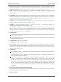
CodeWarrior for
Microcontrollers V10.x
Processor Expert
User Manual
Help version 4.24
Copyright 2011 Freescale Semiconductor, Inc.
PROCESSOR EXPERT is trademark of Freescale Semiconductor, Inc.
-1-
CONTENTS
1. Introduction
4
1.1. Processor Expert Plug-in Overview
1.2. Features
1.3. Concepts
1.4. Benefits of Embedded Components and Processor Expert Technology
1.5. Terms and Definitions Used in Processor Expert
4
5
8
10
11
2. User Interface
13
2.1. Main Menu
13
2.1.1. Processor Expert Options
14
2.2. Project Panel View
2.3. Components Library
15
17
2.3.1. Component Assistant
19
2.4. Inspector View
19
2.4.1. Inspector Items
2.4.2. Items Visibility
2.4.3. Component Inspector
2.4.3.1. Dialog Box for Timing Settings
2.4.3.2. Syntax for the Timing Setup in the Component Inspector
2.4.4. Configuration Inspector
21
22
23
24
27
27
2.5. Target CPU View
2.6. Memory Map View
2.7. Configuration Registers View
28
31
31
3. Application Design
33
3.1. Quick Start in Processor Expert
3.2. Basic Principles
33
34
3.2.1. Embedded Components
3.2.1.1. Component Categories
3.2.1.2. Logical Device Drivers
3.2.2. CPU Components
3.2.2.1. CPU component variants selection
3.2.2.2. Compiler selection
3.2.2.3. CPU Properties Overview
3.2.2.4. Speed Modes Support
3.3. Configuring Components
34
36
38
41
42
43
43
44
45
3.3.1. Interrupts and Events
3.3.1.1. Processor Expert Priority System
3.3.2. Configurations
3.3.3. Design Time Checking: Consequences and Benefits
3.3.4. Timing Settings
3.3.5. Creating User Component Templates
3.3.6. Signal Names
3.3.7. Component Inheritance and Component Sharing
3.3.8. Pin Sharing
3.4. Implementation Details
45
47
50
51
52
54
55
56
57
58
3.4.1. Reset Scenario with PE for HC(S)08, RS08 and 56800/E
3.4.2. Reset Scenario with PE for ColdFire and Kinetis MCUs
3.4.3. Version Specific Information for 56800/E
3.4.4. Version Specific Information for Freescale HC(S)08 and ColdFire V1 derivatives
3.4.4.1. HC(S)08/ColdFire V1 Timers Usage and Sharing
3.4.4.2. Debugging on HC08 Using MON8
3.4.5. Version Specific Information for RS08
-2-
58
60
62
64
66
69
70
Processor Expert User Manual
3.4.5.1. RS08 Timers Usage and Sharing
3.4.6. Version Specific Information for Kinetis and ColdFire+
3.5. Code Generation and Usage
71
74
74
3.5.1. Code Generation
3.5.1.1. Tracking Changes in Generated Code
3.5.2. Predefined Types, Macros and Constants
3.5.2.1. 56800/E Additional Types For SDK Components
3.5.3. Typical Usage of Component in User Code
3.5.3.1. Typical Usage of Peripheral Initialization Components
3.5.3.2. Typical LDD Components Usage
3.5.4. User Changes in Generated Code
3.6. Embedded Component Optimizations
3.6.1. General Optimizations
3.6.2. General Port I/O Optimizations
3.6.3. Timer Components Optimizations
3.6.4. Code Size Optimization of Communication Components
3.7. Converting Project to Use Processor Expert
3.8. Low-level Access to Peripherals
74
76
77
79
83
85
86
87
88
88
89
89
90
90
91
3.8.1. Physical Device Drivers
3.8.2. Processor Expert System Library
3.8.3. Direct Access to Peripheral Registers
92
92
93
3.9. Processor Expert Files and Directories
95
4. Processor Expert Tutorials
96
4.1. Tutorial Project 1 for Kinetis Microcontrollers
96
4.1.1. Tutorial Project 1 for Kinetis, Step 1
4.1.2. Tutorial Project 1 for Kinetis, Step 2
4.1.3. Tutorial Project 1 for Kinetis, Step 3
4.1.4. Tutorial Project 1 for Kinetis, Step 4
96
97
98
99
5. Component Wizard Description
102
-3-
Processor Expert User Manual
Introduction
1. Introduction
Both hardware and software design have progressed with the ever-advancing new technologies emerging
everyday, but their interrelationships and interdependence have been mostly neglected. On one hand, we often
see a good new hardware architecture but the software design is too expensive for such an architecture. On the
other hand, the computerization of nearly all mechanical gadgets all over the modern world leads to the use of
embedded computer systems. In situations where expense is a consideration, embedded computer systems with
efficient software can significantly reduce the overall design cost.
Processor Expert Code Warrior plug-in is designed for rapid application development of embedded
applications for a wide range of microcontrollers and microprocessor systems.
Processor Expert Main features
• The application is created from components called Embedded Components.
• Embedded Components encapsulate functionality of basic elements of embedded systems like CPU core,
CPU on-chip peripherals, FPGA, standalone peripherals, virtual devices, and pure software algorithms, and
change these facilities to properties, methods, and events (like objects in OOP).
• Processor Expert suggests, connects, and generates the drivers for embedded system hardware, peripherals,
or used algorithms. This allows the user to concentrate on the creative part of the whole design process.
• Processor Expert allows true top-down style of application design - the user starts the design directly by
defining the application behavior instead of spending days just trying to make the chip work.
• Processor Expert works with an extensible components library of supported microprocessors, peripherals,
and virtual devices.
• Processor Expert Peripheral Initialization components generate effective initialization code for all on-chip
devices and support all their features.
• Logical Device Drivers (LDD components) are efficient set of Embedded Components that are ready to be
used together with RTOS. They provide a unified hardware access across MCUs allowing to develop simpler
and more portable RTOS drivers or bare board application. See 3.2.1.2 Logical Device Drivers for details.
• Processor Expert allows to examine the relationship between the Embedded Component setup and control
registers initialization.
• The user can create his/her own components using the Component Wizard external tool. See 5 Component
Wizard Description for details.
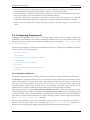
1.1. Processor Expert Plug-in Overview
Processor Expert provides an efficient development environment for rapid application development of the
embedded applications. You can develop embedded applications for a wide range of microcontrollers and
microprocessor systems using Processor Expert.
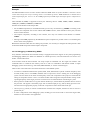
Processor Expert is integrated as a plug-in into the CodeWarrior IDE. You can access Processor Expert from the
CodeWarrior IDE using the Processor Expert menu in the CodeWarrior IDE menu bar. The Processor Expert
plug-in generates code from the Embedded Components and the CodeWarrior IDE manages the project files, and
compilation and debug processes.
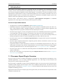
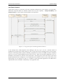
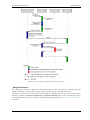
Figure below shows the Processor Expert plug-in that appears when you select the Processor Expert menu in the
CodeWarrior IDE menu bar.
-4-
Processor Expert User Manual
Introduction
Figure 1.1 - CodeWarrior IDE with Processor Expert plug-in active
How to Create a New Project
See the chapter 4 Processor Expert Tutorials or 3.1 Quick Start in Processor Expert for step-by-step instructions
on how to create a new Processor Expert project.
Where to find source code and user modules
Processor Expert generates all drivers during the code generation process. The generated files are automatically
inserted into the active (default) target in the CodeWarrior project. For more information on generated files
please see the chapter 3.5.1 Code Generation.
1.2. Features
Processor Expert has built-in knowledge (internal definitions) about all microcontroller units and integrated
peripherals. The microcontroller units and peripherals are encapsulated into configurable components called
Embedded Components, each of which provides a set of useful properties, methods and events.
An intuitive and powerful User Interface (UI) allows the user to define the system behavior in several steps. A
simple system can be created just by selecting the necessary components, setting their properties to the required
values and maybe also dragging and dropping some of their methods to the user part of the project source code.
-5-
Processor Expert User Manual
Introduction
Processor Expert Key Components
• Graphical IDE
• Built-in detailed design specifications of the Freescale devices
• Code generator
PE Key Features
• Design-time verifications
• MCU selection from multiple MCU derivatives available
• MCU pin detailed description and structure viewing
• Configuration of functions and settings for the selected MCU and its peripherals
• Definition of system behavior during initialization and at runtime
• Design of application from pre-built functional components
• Design of application using component methods (user callable functions) and events (templates for user
written code to process events, e.g. interrupts)
• Customization of components and definition of new components
• Tested drivers
• Library of components for typical functions (including virtual SW components)
• Verified reusable components allowing inheritance
• Verification of resource and timing contentions
• Concept of project panel with ability to switch/port between MCU family derivatives
• Code generation for components included in the project
• Implementation of user written code
• Interface with Freescale CodeWarrior
PE based tool solution offers the following advantages to Freescale MCU customers:
• In all phases of development, customers will experience substantial reductions in
development cost
development time
• Additional benefits in product development process are
Integrated development environment increases productivity
Minimized time to learn Freescale MCU
Rapid prototyping of entire applications
Modular and reusable functions
Easy to modify and port implementations
-6-
Processor Expert User Manual
Introduction
Integrated development environment increases users' productivity
• "This tool lets me produce system prototypes faster because the basic setup of the controller is easier. This
could mean that I will implement more of my ideas into a prototype application having a positive effect on
the specification, analysis and design phase. PE justifies its existence even when used for this purpose alone!"
• "This system frees you up from the hardware considerations and allows you to concentrate on software issues
and resolve them thoroughly."
• "Very good for CPUs with embedded peripherals. It significantly reduces project development time."
Primary Reasons Why Users Feel that Way:
• Processor Expert has built-in knowledge (internal definition) of the entire microcontroller with all its
integrated peripherals.
• Processor Expert encapsulates functional capabilities of microcontroller elements into concepts of
configurable components.
• Processor Expert provides an intuitive graphical UI, displays the microcontroller structure, and allows the
user to take advantage of predefined and already verified components supporting all typically used functions
of the microcontroller.
• Applications are designed by defining the desired behavior using the component settings, drag & drop
selections, utilizing the generated methods and events subroutines, and combining the generated code with
user code.
• Processor Expert verifies the design based on actual microcontroller resource and timing contentions.
• Processor Expert allows the efficient use of the microcontroller and its peripherals and building of portable
solutions on a highly productive development platform.
Minimized Time to Learn Microcontroller
There are exciting possibilities in starting a new project if the user is starting from ground zero even if the user is
using a new and unfamiliar processor.
• The user is able to utilize the microcontroller immediately without studying the microcontroller's
documentation.
• The user is able to implement simple applications even without deep knowledge of programming.
• PE presents all necessary information to the user using built-in descriptions and hints.
• PE has built-in tutorials and example projects.
Rapid Prototyping of Entire Applications
"Processor Expert allows the users to try different approaches in real time and select the best approach for the
final solution. Users are not confined to a pre-determined linear approach to a solution."
• Easy Build of application - based on system functional decomposition (top-down approach)
• Easy MCU selection
• Easy CPU initialization
• Easy initialization of each internal peripheral
• Simple development of reusable drivers
• Simple implementation of interrupt handlers
• Inherited Modularity and reuse
-7-
Processor Expert User Manual
Introduction
• Inherited ease of implementation of system hardware and software/firmware modifications
Modular and Reusable Functions
Processor Expert greatly decreases the start-up time and minimizes the problems of device idiosyncrasies.
• It uses the concept of a function encapsulating entity called Embedded Component with supporting methods
and events
• Uses a library of predefined components
• Uses the concept of device drivers and interrupt handlers that are easy to reapply
• Uses the concept of well-documented programming modules to keep the code well organized and easy to
understand
Note: Processor Expert Embedded Component were formerly called "Processor Expert Embedded Beans."
Easy to modify and port implementations
Processor Expert allows optimal porting to a previously unused processor.
• Supports multiple devices within a project and makes it extremely easy to switch them
• Supports desired changes in the behavior of the application with an instant rebuild
• Supports interfacing of the CodeWarrior IDE
1.3. Concepts
The main task of Processor Expert is to manage CPU and other hardware resources and to allow virtual
prototyping and design.
Code generation from components, the ability to maintain user and generated code, and an event based structure
significantly reduce the programming effort in comparison with classic tools.
Embedded Components
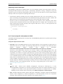
Component is the essential encapsulation of functionality. For instance, the TimerInt component encapsulates all
CPU resources that provide timing and hardware interrupts on the CPU.
Figure 1.2 - Example of TimerInt component (periodical event timer) properties
You'll find many components that we call Embedded Components in the Processor Expert Components library
window. These components are designed to cover the most commonly required functionality used for the
-8-
Processor Expert User Manual
Introduction
microcontroller applications - from handling port bit operations, external interrupts, and timer modes up to serial
asynchronous/synchronous communications, A/D converter, I2C, CAN etc.
A component provides a clear interface . By setting properties , a user defines the future behavior of the
component in runtime. The user controls properties in design time by using the Component Inspector. Runtime
control of the component function is done by the Methods. Events are interfacing hardware or software events
invoked by the component to the user's code.
The user can enable or disable the appearance (and availability) of methods of the component in generated
source code. Disabling unused methods could make the generated code shorter. See 3.6.1 General Optimizations
for details.
Events, if used, can be raised by interrupt from the hardware resource such as timer, SIO or by pure software
reason, such as overflow in application runtime. You can enable or disable interrupts using component methods
and define priority for event occurrence and for executing its Interrupt Service Routine (ISR). The hardware ISR
provided by the component handles the reason for the interrupt. If the interrupt vector is shared by two (or more)
resources, then this ISR provides the resource identification and the user is notified by calling the user event
handling code.
Creating Applications
Creation of an application with Processor Expert on any microcontroller is very fast. To create an application,
first choose and set up a CPU component, add other components, modify their properties, define events and
select Generate Code . Processor Expert generates all code (well commented) from components according to
your settings. See 3.5.1 Code Generation for details.
This of course is only part of the application code that was created by the "virtual application engineer" Processor Expert CPU knowledge system and solution bank. The solution bank is created from hand written and
tested code optimized for efficiency. These solutions are selected and configured in the code generation process.
Enter your code for desired events, provide main code, add existing source code - and build the application using
classic tools - compiler, assembler - and debug it before the final burn-in. These are typical steps when working
with Processor Expert.
Other components may help you to very quickly include pictures, files, sounds, and string lists in your
application .
Processor Expert has built-in knowledge (internal definitions) about the entire MCU with all integrated
peripherals. The MCU units and peripherals are encapsulated into configurable components called Embedded
Components and the configuration is fast and easy using a graphical Component Inspector.
Peripheral Initialization Components are a subset of Embedded Components allow the user to setup
initialization of the particular on-chip device to any possible mode of operation. The user can easily view all
initialization values of the MCU produced by Processor Expert with highlighted differences between the last and
current properties settings.
Processor Experts performs a design time checking of the settings of all components and reports errors and
warnings notifying users about wrong property values or conflicts in the settings with other components in the
project.
Processor Expert contains many useful tools for exploring a structure of the target MCU showing the details
about the allocated on-chip peripherals and pins.
Processor Expert generates a ready-to-use source code initializing all on-chip peripherals used by the
component according to the component setup.
-9-
Processor Expert User Manual
Introduction
RTOS support
Processor Expert provides a set of LDD components (Logical Device Drivers) that support generation of driver
code that can be integrated with RTOSes (Real Time Operating Systems). Please see details in the section 3.2.1.2
Logical Device Drivers
1.4. Benefits of Embedded Components and Processor Expert
Technology
The key benefit of Embedded Components is using components in software design. Embedded Components
provide hardware encapsulation in the form of a platform-independent standard. Different players in the
embedded market should benefit from such a standardized approach.
Microprocessor producers
Each year microprocessor producers introduce many new microprocessor families or derivatives. As the
complexity of microprocessors increases, programmers must handle more and more registers to get the required
functionality. Classical development tools usually do not support the rapid prototyping phase of design, and
classical programming languages are unable to describe the on-chip peripherals structure efficiently. On the
other hand, microprocessor producers need to speed up the learning, design and coding processes for their
customers.
For the designers, Processor Expert and its configuration and code generation features eliminate the necessity to
be otherwise preoccupied with the hardware dependencies.
Producers of intelligent peripheral I/Os and other devices
Complex and feature-rich peripherals and controllers require immense efforts to use them efficiently, even if
device drivers are supplied by the factory. But imagine the possibility of supporting customers with components
providing a standard software interface that allows building applications and using new hardware device features
easily.
The Processor Expert environment allows this — customers can download new components from the internet
and install them into Processor Expert.
Producers of hardware of microprocessor systems
Microprocessor boards that are to be programmed by a customer must be well supported by software. Processor
Expert can handle software configuration and generation of drivers for microprocessor devices and off-chip
peripheral devices. Creating an application using Processor Expert takes usually 70% less time than with
standard Integrated Development Environments (IDEs) containing only a source code editor/compiler/debugger.
Producers of OS
Processor Expert can be used to build an OS kernel or OS drivers. Also, due to its open component architecture
and support of pure software components, Processor Expert can be used to build applications benefiting from
underlying operating system services.
- 10 -
Processor Expert User Manual
Introduction
Educational institutes
Microprocessor-oriented courses can benefit from the information available in Processor Expert about
microprocessor structures and hardware independence delivered by Processor Expert . Design of applications
begins with definition of functionality, which can be obtained very quickly by building the application from
Embedded Components. Students can get the results very fast without facing problems that are not related to the
subject of the course, for example compiler bugs and errors in the documentation.
Hardware and software developers
Shortening of the design and learning phase, speeding up of the deployment of new components, full use of
hardware using tested software components, reduction in time and cost of design — all these are keys to success
provided by Processor Expert.
1.5. Terms and Definitions Used in Processor Expert
Component - An Embedded Component is a component that can be used in Processor Expert . Embedded
Components encapsulate the functionality of basic elements of embedded systems like CPU core, CPU on-chip
peripherals, standalone peripherals, virtual devices and pure software algorithms and wrap these facilities to
properties, methods, and events (like objects in OOP). Components can support several languages (ANSI C,
Assembly language or other) and the code is generated for the selected language.
Component Inspector - Window with all parameters of a selected component: properties, methods, events.
Bus clock - A main internal clock of the CPU. Most of the CPU timing is derived from this value.
CPU Component - Component that encapsulates the CPU core initialization and control. This component also
holds a group of settings related to the compilation and linking, such as Stack size, Memory mapping, linker
settings. Only one CPU component can be set active as the target CPU. See 3.2.2 CPU Components for details.
Component Driver - Component drivers are the core of Processor Expert code generation process. Processor
Expert uses drivers to generate the source code modules for driving an internal or external peripheral according
to the component settings. A Component can use one or more drivers.
Counter - Represents the whole timer with its internal counter.
Events - Used for processing events related to the component's function (errors, interrupts, buffer overflow etc.)
by user-written code. See 3.2.1 Embedded Components for details.
External user module - External source code attached to the PE project. The external user module may consist
of two files: implementation and interface (*.C and *.H).
Free running device - Virtual device that represents a source of the overflow interrupt of the timer in the free
running mode.
High level component - Component with the highest level of abstraction and usage comfort. An application
built from these components can be easily ported to another microcontroller supported by the Processor Expert.
They provide methods and events for runtime control. See 3.2.1.1 Component Categories for details.
Internal peripherals - internal devices of the MCU such as ports, timers, A/D converters, etc. usually controlled
by the CPU core using special registers.
ISR - Interrupt Service Routine — code which is called when an interrupt occurs.
- 11 -
Processor Expert User Manual
Introduction
LDD components - Logical Device Driver components. The LDD components are efficient set of components
that are ready to be used together with RTOS. They provide a unified hardware access across MCUs allowing to
develop simpler and more portable RTOS drivers. See 3.2.1.1 Component Categories for details.
Low level component - a component dependent on the peripheral structure to allow the user to benefit from the
non-standard features of a peripheral. The level of portability is decreased because of this peripheral dependency.
See 3.2.1.1 Component Categories for details.
MCU - Microcontroller Unit — microcontroller used in our application.
Methods - user callable functions or sub-routines. The user can select which of them will be generated and
which not. Selected methods will be generated during the code generation process into the component modules.
Module - Source code module — could be generated by Processor Expert (Component modules, CPU Module,
events.c) or created by the user and included in the project (user module).
OOP - Object-oriented programming (OOP) was invented to solve certain problems of modularity and
reusability that occur when traditional programming languages such as C are used to write applications.
PE - Abbreviation of Processor Expert that is often used within this documentation.
PESL (Processor Expert System Library) is dedicated to power programmers, who are familiar with MCU
architecture - each bit and each register. PESL provides the macros to access the peripherals directly, so PESL
should be used only in some special cases. See 3.8.2 Processor Expert System Library for details.
Peripheral Initialization component - encapsulates the whole initialization of the appropriate peripheral.
Components that have the lowest levels of abstraction and usage comfort. See 3.2.1.1 Component Categories for
details. They usually do not support any methods or events except the initialization method. The rest of the
device driver code needs to be written by hand using either PESL or direct control of the peripheral registers. See
3.8 Low-level Access to Peripherals for details.
Popup menu - this menu is displayed when the right mouse button is pressed on some graphical object.
PLL - Phase Locked Loop. This circuit is often built-in inside the CPU and can be used a main source of the
clock within the CPU.
Prescaler - A fixed or configurable device that allows to divide or multiply a clock signal for a peripheral CPU
peripheral or its part.
Properties - Parameters of the component. Property settings define which internal peripherals will be used by
the component and also initialization and behavior of the component at runtime.
RTOS - Real Time Operating System is an operating system (OS) intended for real-time applications.
Target CPU - The CPU derivative used in a given project.
Template - Component Template — component with preset parameters.
User-defined Component Template - User-defined component template is a component with preset parameters
saved under a selected name. Also the name of the author and short description can be added to the template.
User module - Source code module created or modified by the user. (Main module, event module or external
user module).
Xtal - A crystal - a passive component used as a part of an oscillator circuit.
- 12 -
Processor Expert User Manual
User Interface
2. User Interface
Processor Expert menu is integrated as a plugin in the CodeWarrior IDE offering set of views. There is also a
menu item named "Processor Expert" offering PE-related commands.
See Processor Expert plug-in Main menu page for description of individual items.
The user interface of Processor Expert consists of the following windows :
Project Editing Views
• Project panel - Shows projects with files and components within the projects.
• Inspector - Allows the user to setup components of the project.
• Components Library - Shows all supported components including CPU components and component
templates.
• Target CPU - Shows CPU package, structure and components connected to internal peripherals.
Project Information Views
• Configuration Registers - Shows overview of the peripheral initialization settings for the current CPU.
• Memory Map - Shows the CPU address space and internal and external memory mapping.
2.1. Main Menu
The Processor Expert Plug-in is integrated into the CodeWarrior Eclipse IDE as plugin application. The IDE
main menu contains a new menu item named "Processor Expert".
The Processor Expert menu includes the following command(s):
• Component Wizard - Invokes Component wizard tool. See 5 Component Wizard Description for details.
• Show views - Shows standard Processor Expert windows in case they are hidden.
• Hide views - Hides Processor Expert views.
• Import package - This command allows to select and install Processor Expert update packages (.PEUpd)
files. These files can be for example created in Component Wizard by exporting a user's component.
For commands related to individual projects please follow to 2.2 Project Panel View.
For Processor Expert related settings and options please follow to 2.1.1 Processor Expert Options.
- 13 -
Processor Expert User Manual
User Interface
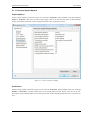
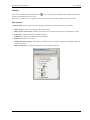
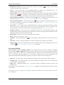
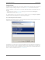
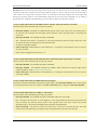
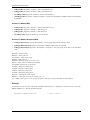
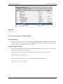
2.1.1. Processor Expert Options
Project Options
Project options related to Processor Expert can be found in Properties dialog available using the command
Project > Properties . Then select Processor Expert page in the list on the left. Description of the individual
options can be found in the hint window displayed when the cursor is placed on an item.
Figure 2.1 - Project Properties Dialog
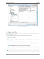
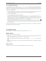
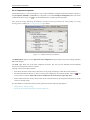
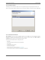
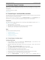
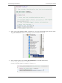
Preferences
Global settings related to Processor Expert can be found in Preferences dialog available using the command
Window > Preferences . The PE related items can be found under Processor Expert in the list on the left.
Description of the individual options can be found in the hint window displayed when the cursor is placed on an
item.
- 14 -
Processor Expert User Manual
User Interface
Figure 2.2 - Preferences Dialog
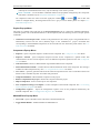
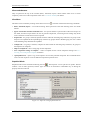
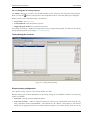
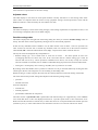
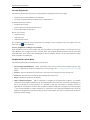
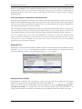
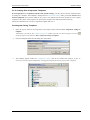
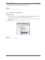
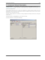
2.2. Project Panel View
Processor Expert project panel shows the project tree with the Processor Expert items listed within the
ProcessorExpert.pe project branch.
When the user unfolds the Processor Expert project files the following items are shown:
• Configurations of the project.
• Operating System - contains special components that provide operating system interface and configuration
if there are any used.
• CPUs - contain CPU components included in the project
• Embedded Components included in the project. Every component inserted in the project is displayed in the
project panel and may have a sub tree showing items available for the component (please note that
components can offer only some or even none of these items):
Methods - Methods allow runtime control of the component's functionality.
Event routines - Events allow handling of the hardware or software events related to the component. If
the event is disabled, the name of the event is shown. For enabled events, the name of the handling
function is shown.
ISRs - Represent component-related interrupt routines that can be created by the user for low-level
interrupt processing. For items, whose ISR names have been specified within component settings, a
user-specified name of an ISR and name of the interrupt vector is shown. If an ISR name is not specified
- 15 -
Processor Expert User Manual
User Interface
(interrupt has to be disabled in this case), only the interrupt vector name is present.
PESL commands - low-level PESL commands related to the peripheral configured by this component.
This folder is available only for Peripheral Initialization components.
All component's items have status icons that signify the enabled ( ) or disabled ( ) state. If this state
cannot be changed directly, the background of the icon is gray. For more details please see chapter 3.2.1
Embedded Components.
Project Pop-up Menu
This menu is available using right-click at the ProcessorExpert.pe file. It contains the standard CodeWarrior
commands (please refer to the documentation for the description) with the following Processor Expert specific
commands:
• Generate Processor Expert Code - Invokes code generation for the current project. The generated files are
automatically inserted into the active (default) target in the CodeWarrior's project. Generated files
corresponding to the Embedded Components can be accessed from the "Generated_Code" folder. See 3.5.1
Code Generation for details.
Component Pop-up Menu
• Inspector - opens Component Inspector window for the component. See 2.4 Inspector View for details.
• Inspector - Pinned - opens Component Inspector window for the component in "pinned" mode. This
command allows to have several inspector views for different components opened at once. See 2.4 Inspector
View for details.
• Code Generation - allows to disable/enable of generated module for the component.
• Select Distinct/Shared mode - switches between shared and distinct mode of the component. This setting is
available for LDD components only. See 3.2.1.2 Logical Device Drivers for details.
• View source - opens the generated code from the selected component for the source code editor. Please note
that the code is available only after successful code generation.
• Component Enabled - enables/disables component in the project.
• Remove component from project - Deletes the component from the project.
• Help on component - shows on-line help for the component.
• Save Component Settings As Template - Creates a template of the selected component. See 3.3.5 Creating
User Component Templates for details.
• Configuration registers - Opens the Configuration registers view for the peripheral initialized by the
selected component. See 2.7 Configuration Registers View for details.
Method/Event Pop-up Menu
• View Code - Opens code editor at the code of the selected method/event.
• Toggle Enable/Disable - Enables/Disables the Method/Event.
- 16 -
Processor Expert User Manual
User Interface
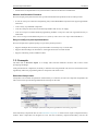
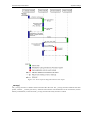
Figure 2.3 - Processor Expert in the Project Panel
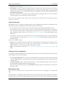
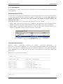
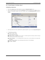
2.3. Components Library
The Components Library view shows supported embedded components including CPU components and
component templates. It lets the user select a desired component or template and add it to the project.
Modes
The Components Library has the following four tabs allowing the user to select components in different modes:
• Component Categories - Contains all available components. The components are sorted in a tree based on
the categories defined in the components. See 3.2.1.1 Component Categories for details. Please see below for
menu and control details.
• Alphabetical - Shows alphabetical list of the available components.
• Assistant - Guides the user during the component selection process. The user answers a series of questions
that finally lead to a selection of a component that suits best for a required function. See 2.3.1 Component
Assistant for details.
• CPUs - Contains list of the available CPU components.
Component names are colored black and the component template names are colored blue. The components that
are not supported for the currently selected target processor are gray. By double-clicking on the component, it
is possible to insert the component into the current project. The description of the component is shown in a hint.
- 17 -
Processor Expert User Manual
User Interface
Filtering
Filter can be activated using the filtering icon
. If it's active, only the components that could be used with the
currently selected target CPU are shown .
If the filter is inactive, Processor Expert also shows components that are not available for the current CPU.
Pop-up menu
A pop-up menu opens by right-clicking a component or folder. It contains the following commands:
• Add to project- Adds the component to the current project.
• Add to project with wizard- Adds the component to the current project and opens a configuration wizard.
• Expand all - Expands the folder and all its subfolders.
• Collapse all - Collapses the folder and all its subfolders.
• Refresh- Refreshes the view area.
• Deleted Selected Template - This option is available only for templates. Removes the template from the
Components Library.
• Help on component - Opens help information for the selected component.
- 18 -
Processor Expert User Manual
User Interface
2.3.1. Component Assistant
The Component Assistant is a mode of Components Library window. It guides the user during the selection of
components, that is basic application building blocks. The user answers a series of questions that finally lead to a
selection of a component that suits best for a required function. In this mode the Components Library window
consists of the following parts:
• History navigation buttons and the history line showing answers for already answered questions. The user
can walk through the history using the arrow buttons or by clicking the individual items.
• A box with a current question.
• A list of available answers for the current question.
If the answer already corresponds to a single component (it has an icon of the component and there is a
[component name] at the end of the list line) and user double-clicks it, its added into the project. Also, you
can right-click on the line to open the pop-up menu of the component, allowing to add it into the project or
view its documentation (for details see 2.3 Components Library help page).
If more questions are necessary for the component selection, the line with the answer contains a group icon
and in brackets a number of components that still can possibly be selected. After clicking on such line a next
question is displayed.
This mode of Components Library doesn't offer addition of CPU components. If you would like to add another
CPU component, please switch to CPUs tab.
2.4. Inspector View
Inspector allows to view and edit attributes of the item selected in the Project Panel.
Window Columns
Inspector window contains the three columns:
• Name - Name of the item to be selected. Groups of items may be collapsed/expanded by double clicking on
the first line of the group with its name, it has '+' or '-' sign on the left.
• Value - the settings of the items are made in this column. See chapter 2.4.1 Inspector Items for list of item
types.
• Details - the current setting or an error status may be reflected on the same line, in the rightmost column of
the inspector.
Read only items
Some items are read-only so the user could not change the content. Such values are gray.
- 19 -
Processor Expert User Manual
User Interface
View mode buttons
They are placed at the top of the window (Basic, Advanced, Expert). These buttons allow users to switch
complexity of the view of the component's items. See 2.4.2 Items Visibility for details.
View Menu
This menu can be invoked by clicking on the down arrow icon
. The menu contains the following commands:
• Basic, Advanced, Expert - view mode switching. These options have the same meaning as the view mode
buttons.
• Ignore Constraints and non-Critical Errors - this option enables a special mode of Processor Expert. In
this mode, Processor Expert allows the user to generate output files, even though some settings may break
some constraints or limits and errors are reported.
• Expand All - if a group is selected, expands all items within the selected group. Otherwise, all groups in the
Inspector are expanded. If the expanded group contains any groups that are disabled (gray), the user is asked
if the disabled groups should all be expanded.
• Collapse All - if a group is selected, collapses all items within the selected group. Otherwise, all groups in
the Inspector are collapsed.
• Help on Component - shows a help page for the component.
• Save component settings as template - creates a template for the current component settings. See 3.3.5
Creating User Component Templates for details.
• Open pinned view - opens a copy of the inspector for currently selected component. This command allows
to have several inspector views for different components opened at once.
Graphical Mode
Graphical mode can be switched on/off using the icon
. The instpector view is split into two panels. The left
contains a list of items (proerties) and the right one allows an anternative comfortable way of editing the
property selected on the left.
Figure 2.5 - Inspector with graphical mode on
- 20 -
Processor Expert User Manual
User Interface
Pop-up Menu
This menu is invoked by right-clicking a specific inspector item. The menu contains the following commands:
• Expand All - if a group is selected, expands all items within the selected group. Otherwise, all groups in the
Inspector are expanded. If the expanded group contains any groups that are disabled (gray), the user is asked
if the disabled groups should all be expanded.
• Collapse All - if a group is selected, collapses all items within the selected group. Otherwise, all groups in
the Inspector are collapsed.
• Help on Component - shows a help page for the component.
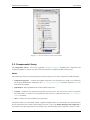
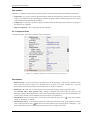
2.4.1. Inspector Items
The following types of the items could be found in the Inspector
Figure 2.6 - Example component with various inspector item types
Descriptions
• Boolean Group - A group of settings controlled by this boolean property. If the group is enabled, all the
items under the group are valid; if it is disabled, the list of items is not valid. Clicking the + sign will
show/hide the items in the group but doesn't affect value or validity of the items.
• Boolean yes / no - The user can switch between two states of the property using a drop-down menu.
The Generate code / Don't generate code settings of methods and events works the same way and
determines whether the implementation code for the corresponding method or event will be generated or not
(you may thus generate only the methods and events used by your application).
• Enumeration - Selection from a list of values. If the user clicks the arrow icon (
values for the property is offered.
), a list of the possible
• Enumeration Group - A list of items. Number of visible (and valid) items in the group depends on chosen
value. Clicking the arrow icon ( ) will show a list of the possible values of the property. Clicking the + sign
shows/hides the items in the group but doesn't influence value or validity of the items.
- 21 -
Processor Expert User Manual
User Interface
• File/Directory Selection - Allows to specify a file or directory. Clicking the
window allowing to select a file/directory.
icon opens a system dialog
• Group - A list of items that can be expanded/collapsed by clicking on the plus/minus icon or by
double-clicking at the row. Values of the items in the group are untouched.
• Integer Number - The user can insert a number of a selected radix. Radix of the number could be switched
using the icons
(D = Decimal ,H = Hexadecimal, B = Binary). Only reasonable radixes are offered
for the property. If the radix switching icon is not present, Processor Expert expects the decimal radix.
• Link to Inherited component - The down-arrow button
allows to change the ancestor from the list of
possible ancestor. See 3.3.7 Component Inheritance and Component Sharing for details.
• Link to shared component - The down-arrow button
allows to change the component from the list of
the available components or add a new component to the project . See 3.3.7 Component Inheritance and
Component Sharing for details.
• List of items - A list of items may be expanded/collapsed by clicking on the plus/minus button in the left
side of the row or by double clicking on the row. The user may add/remove items by clicking on the
plus/minus button. The items in the list can be arranged using the related pop-up menu commands.
• Peripheral selection - The user can select a peripheral from the list of the available peripherals. The
peripheral that are already allocated have the component icon in the list. The properties that conflicts with the
component settings have the red exclamation mark.
• Real Number - The user can insert any real (floating point) number.
• String - Allows to enter any text or value
• String list - Clicking the dialog button
lines.
opens the simple text editor that allows to enter an array of text
• Time, Date - Allows to setup the Time/Date in a format according to the operating system settings.
• Timing settings - Allows a comfortable setting of the component's timing. The timing dialog box opens on
clicking on . See 2.4.3.1 Dialog Box for Timing Settings for details.
2.4.2. Items Visibility
Processor Expert supports selectable visibility of the component items. Each item is assigned a predefined
level of visibility. Higher visibility level means that items with this level are more special and rarely used than
the others with the lower visibility level. Component Inspector displays only items on and below the selected
level. It could help especially beginners to set only basic properties at first and do optimization and
improvements using advanced and expert properties or events later. There are three visibility levels:
• Basic view - The key and most often used items that configure the basic functionality of the components.
• Advanced view - All items from Basic view and the settings that configure some of more advanced and
complex features of the component.
• Expert view - Maximum visibility level - All possible settings, including all settings from basic and
advanced view.
The visibility can be switched in the Component Inspector using Basic, Advanced and Expert buttons or within
its view menu.
Note: If an error occurs in a property with a higher visibility level than the level currently selected, then too this
error is displayed.
- 22 -
Processor Expert User Manual
User Interface
2.4.3. Component Inspector
Component inspector is one of the Inspector view variants intended to configure component settings. It allows to
setup Properties, Methods, and Events of a component. Use command Help on Component from View menu
(ivoked by the down arrow icon
) to see documentation for currently opened component.
Note: Property settings influencing the hardware can often be better presented by the CPU package view using
the Target CPU window. See 2.5 Target CPU View for details.
Figure 2.7 - Component Inspector Window
The Build options page is present only in the CPU component and it provides access to the settings related to
linker and compiler.
The Used page shows list of the CPU component resources. The user can also manually block individual
resources for using them in Processor Expert.
The page consists of the three columns:
• First shows the name of the resource. Resources are in groups according to which device they belong to.
• Second column allows the user to reserve resource (for example pin) for external module. Click on
to reserve/free a resource. Reserved resource could not be use in Processor expert any more.
icon
• Third column shows the current status of the resource and the name of the component which uses it (if the
resource is already used).
For more details on component inspector items, please see also the following sub-chapters
• Dialog Box for Timing Settings
• Syntax for the Timing Setup in the Component Inspector
- 23 -
Processor Expert User Manual
User Interface
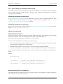
2.4.3.1. Dialog Box for Timing Settings
The Timing dialog box provides a user-friendly interface for the settings of the component timing features.
When you click the
button of a timing item in the Component Inspector, the Timing dialog box is displayed.
Before you start to edit component timing you should set:
• Target CPU in the Project Panel
• Used peripherals in the component's properties
• Supported speed modes in the component's properties
The settings are instantly validated according to the Processor Expert timing model. For details on the timing
settings principles please see the chapter 3.3.4 Timing Settings.
Timing Dialog Box Controls
Figure 2.8 - Timing Settings Dialog
Runtime setting configuration
Note: Runtime setting cannot be selected in the BASIC view mode.
Runtime setting type selection determines how the timing setting can be modified at runtime. The following
options are available:
• fixed value - Timing cannot be changed at runtime.
• from a list of values - Allows to change the timing by selecting one of predefined values (from the list)
using component method "SetXXXMode". This method sets the value(s) corresponding to the selected
timing into the appropriate prescaler and other peripheral register(s). The values (modes) in the list can be
- 24 -
Processor Expert User Manual
User Interface
added/removed by editing the timing values table.
• from interval - Allows to change a timing freely within a selected interval, while all values of the interval
are selected with specified precision. Prescaler value is fixed in this mode, timing is set only using
compare/reload registers value. It means that it has to be possible to reach all values within the interval
by using the same prescaler.
Please note that this kind of runtime setting requires runtime computations that can be time and space
consuming and may not be supported on all microcontrollers.
Note: Some of the methods used for runtime setting of timing will be enabled only if the appropriate runtime
setting type is selected.
Timing values table
This table allows to set or modify a requested value(s) for the configured timing. Each row represents one time
value and the number of rows depends on the selected type of runtime setting.
• For the option "fixed value", there is only one row (Init.Value) containing the fixed initialization value.
• For the option "from a list of values", there is one row for each of the possible timing modes. It is possible to
enter 16 possible values (modes). The empty fields are ignored. The user can drag and drop rows within the
table to change their order. Please see the section Runtime setting configuration within this chapter for more
information.
• For the option "from interval", the table has three rows that contain the Initial value, low limit and high limit
of the interval. Please see the section Runtime setting configuration within this chapter for details on this type
of runtime setting.
There are two editable columns:
• Value - Fill in a requested time value (without units). The drop-down arrow button allows to display a list of
neighboring values and the user can select one of them. There is also possible to set the value by
double-clicking on a value from the possible settings table (see below).
• Units - Time units for the value. See 2.4.3.2 Syntax for the Timing Setup in the Component Inspector for
details.
Timing precision configuration
It is possible to specify desired precision of the timer settings by using one of the following settings (which one
is used depends on the type of the timing) :
• The field Error allowed allows to specify a tolerated difference between the real timing and the requested
value. The Unit field allows to specify the units for the error allowed field (time units or a percentage of the
requested value).
• The Min. resolution field is used for setting interval or capture component timing. Allows the user to
specify maximal acceptable length of one tick of the timer.
In the case of interval settings type, the % of low limit (percentage of the low limit value) can be used as the
unit for this value.
Minimal timer ticks
Note: This item is available only for setting of period in components where it's meaningful, for example PWM,
PPG.
This item allows to set a minimal number of timer-ticks in period. It means that it will be possible to set a duty of
the output signal to at least the specified number of distinct values for any period of the output signal at runtime.
- 25 -
Processor Expert User Manual
User Interface
Value 0 means no requirements for the timer settings.
Adjusted values
This table displays a real values for each speed mode the currently selected row in the Timing values table.
These values are computed from the chosen on-chip peripheral settings, selected prescaler(s) value and the
difference between a value selected by the user and the real value.
Status box
The status box displays a status of the timing setting(s). If the timing requirements are impossible to meet, a red
error message is displayed, otherwise it's blank and gray.
Possible settings table
This table is displayed on the right side of the timing dialog box when you click the Possible settings button on
the top. The table shows values supported by the target CPU for the selected peripheral.
If there are only individual values available to set, the table contains a list of values - each row represents one
value. If there are intervals with a constant step available, each row contains one of the intervals with three
values: From, Till - minimum and maximum value, Step - a step between values within the interval.
The way the values are displayed may be dependent on
• Runtime setting type - If it's "fixed value" or "from list of values" — the values present in more rows
(overlapping intervals) are shown only once. If the "from time interval" runtime setting type is used, all
intervals that can be set by various prescalers combinations are shown, even if they overlap. It's because
intervals can differ in resolution, that is number of individual timing steps that can be achieved within them.
• Timing unit - If a frequency unit is used (e.g. Hz, kHz), the step column is not visible
By clicking on the table header, there is possible to order the rows as per selected column. By clicking the same
column again, the user can arrange the rows in ascending or descending order.
Double clicking on a value will place the value into the currently edited row within the Timing values table.
The values listed in the possible settings table depend on the following timing settings:
• prescalers
• minimal timer ticks
and it also depend on
• selected CPU
• selected peripheral
• speed-modes enabled for the component
The table contains a speed mode tabs (speed modes and related settings are supported only in the EXPERT
view mode) that allow to filter the displayed intervals for a specific speed mode or show intersection of all.
Please note that the intersection contains only a values that can be set in all speed modes with absolute precision
(without any error), so some values that are still valid due to non-zero Error allowed value are not shown.
- 26 -
Processor Expert User Manual
User Interface
2.4.3.2. Syntax for the Timing Setup in the Component Inspector
The properties that contain timing settings can be configure using the timing dialog box (For details, please see
the chapter 2.4.3.1 Dialog Box for Timing Settings) or directly by entering the timing value. If the timing values
are specified directly, it's necessary to type not only a value (integer or real number) but also the unit of that
value. The following units are supported:
• microseconds - A value must be followed by us.
• milliseconds - A value must be followed by ms.
• seconds - A value must be followed by s.
• CPU ticks - A unit derived from the frequency of external clock source. If there is no external clock enabled
or available, it is derived from the value of internal clock source. A value must be followed by ticks.
• Timer ticks - A unit representing number of changes (for example increments) of the counter used by the
component. The real time of one tick is incfluenced by input clock set for the timer.
• Hertz - A value must be followed by Hz.
• kilohertz - A value must be followed by kHz.
• megahertz - A value must be followed by MHz.
• bit/second - A value must be followed by bits.
• kbit/second - A value must be followed by kbits.
Example
If you want to specify 100 milliseconds, enter 100 ms
For more details on timing configuration, please see the chapter 3.3.4 Timing Settings.
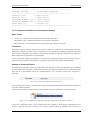
2.4.4. Configuration Inspector
Configuration Inspector is a variant of an Inspector Window. It shows the settings that belong to one
configuration. It could be invoked from configurations pop-up menu in the Project Panel (Click on a
configuration with the right button and choose the Configuration Inspector). For details on configurations please
see the chapter 3.3.2 Configurations.
Properties
The Properties tab contains optimization settings related to the configuration. These setting should be used when
the code is already well debugged. They could increase speed of the code, but the generated code is less
protected for the unexpected situations and finding errors could be more difficult.
Please note that some of the options may not be present for all Processor Expert versions.
• Ignore range checking - This option can disable generation of the code, that provides testing for parameter
range. If the option is set to "yes", methods do not return error code ERR_VALUE neither ERR_RANGE. If
the method is called with incorrect parameter, it may not work correctly.
• Ignore enable test - This option can disable generation of the code, that provides testing if the
component/peripheral is internally enabled or not. If the option is set to "yes", methods do not return error
code ERR_DISABLED neither ERR_ENABLED. If the method is called in unsupported mode, it may not
work correctly.
- 27 -
Processor Expert User Manual
User Interface
• Ignore speed mode test - This option can disable generation of the code, that provides a testing, if the
component is internally supported in the selected speed mode. If the option is set to "yes", methods do not
return error code ERR_SPEED. If the method is called in the speed mode when the component is not
supported, it may not work correctly.
• Use after reset values - This option allows Processor Expert to use the values of peripheral registers which
are declared by a chip manufacturer as the default after reset values. If the option is set to "no", all registers
are initialized by a generated code, even if the value after reset is the same as the required initialization
value. If the option is set to "yes", the register values same as the after reset values are not initialized.
• Complete initialization in Peripheral Init. Component - This option can disable shared initialization
peripheral in Init methods of Peripheral Initialization Components. If this option is set to "yes", the complete
peripheral initialization is provided in Init method, even for parts that are already initialized in CPU or
elsewhere. The could mean longer code, but the initialization can be repeated in application using the Init
method.
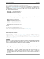
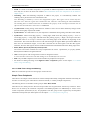
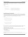
2.5. Target CPU View
This view displays selected target MCU with its peripherals and pins.
Figure 2.9 - Target CPU view example
Control Buttons
The meanings of the buttons are:
•
•
•
Zoom in - Increases the detail level of the view. The whole picture might not fit the viewing area.
Zoom out - Decreases the detail level of the view. Processor Expert tries to fit the whole picture to the
viewing area.
Rotate - Rotates the package clockwise.
- 28 -
Processor Expert User Manual
User Interface
•
Resources (available for BGA type packages only) - Selects Resources view mode that shows a top side
of the package without pins but including list of peripherals and showing their allocation by components.
•
Pins (available for BGA type packages only)- Selects Pins view mode that shows a bottom side of the
package with pins. The peripherals are not shown in this mode beacause the surface is covered with pins.
Pins
The following information about each pin is displayed on the CPU picture:
(in case of BGA type package the pins are displayed only in the Pins view mode)
• pin name (default or user-defined)
• icon of a component that uses (allocates) the pin
• direction of the pin (input, output, or input/output) symbolized by blue arrows, if a component is connected
Pin names are shortened and written either from left to right or from top to bottom and are visible only if there is
enough space in the diagram.
Some signals and peripherals cannot be used by the user because they are allocated by special devices such as
power signals, external or data bus. The special devices are indicated by a special blue icons, for example
The allocation of peripherals by special devices can be influenced by CPU component settings.
.
In case of BGA package, the pins that are used by some component are colored yellow. Move the cursor on the
pin to get detailed information.
Hints
Pin hint contains:
• number of the pin (on package)
• both names (default and user-defined)
• owner of the pin (component that allocates it)
• short pin description from CPU database
Component icon hint contains:
• component name
• component type
• component description
Shared Pins
If a pin is shared by multiple components, the line connecting the pin to the component has a red color. See 3.3.8
Pin Sharing for details.
- 29 -
Processor Expert User Manual
User Interface
On-chip Peripherals
The following information about each on-chip peripheral is displayed on the CPU package:
• peripheral device name (default or user-defined)
• icon of the component that uses (allocates) the peripheral device
Peripheral device hint contains:
• peripheral device name
• owner of the pin (component that allocates it)
• short peripheral device description
Hint on icon contains:
• component name
• component type
• component description
If a peripheral is shared by several components (for example: several components may use single pins of the
same port), the
icon is displayed.
Note for peripherals working in several modes:
Some peripherals work in several modes and these peripherals can be represented by a several devices in the
CPU databases. For example, the device "TimerX_PPG" and "TimerX_PWM" represents TimerX in the PPG
and PWM mode. These devices can be displayed on the CPU package, but they are also represented as a single
block in the MCU block diagram.
Peripheral/Pin Pop-up Menu
The following commands are available in the pop-up menu:
• Show Peripheral Initialization - shows initialization values of all "control, status and data" registers. This
option is supported for all devices displayed on a CPU package. See 2.7 Configuration Registers View for
details.
• Zoom in - Increases the detail level of the view. The whole picture might not fit the viewing area.
• Zoom out - Decreases the size of the picture and detail level of the view.
• Rotate - Rotates the package by 90 degrees.
• Add Component/Template - adds a component or template for the appropriate peripheral: all available
components and templates suitable for the selected peripheral are listed. The components and templates in
the list are divided by a horizontal line. It is possible to add only components or templates which are
applicable for the peripheral. It means that is possible to add the component or template only if the peripheral
is not already allocated to another component or components. The components/templates that cannot be
added to the peripheral are grayed in the pop-up menu as unavailable. This option is supported for all devices
displayed on CPU package.
- 30 -
Processor Expert User Manual
User Interface
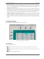
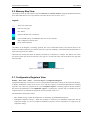
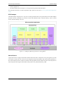
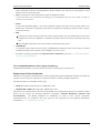
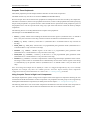
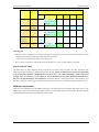
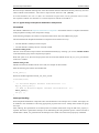
2.6. Memory Map View
This window shows the CPU address space and internal and external memory mapping. Detailed information
for an individual memory area is provided as a hint when the user moves cursor over it.
Legend:
white: non-usable space
dark blue: I/O space
blue: RAM
light blue: ROM, OTP or Firmware
cyan: FLASH memory or EEPROM. This area can also contain a
flash configuration registers area.
black: external memory
The address in the diagram is increasing upwards. The sizes of individual memory areas blocks drawn in the
window are different from the ratio of their real sizes to improve readability of the information (Small blocks are
larger and large blocks are smaller).
The black line-crossed areas show the memory allocated by a component or compiler. The address axis within
one memory block goes from the left side to the right (i.e. the left side means start of the block, the right side
means the end).
Figure 2.10 - Sample Of Used Part Of The Memory Area
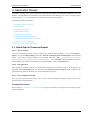
2.7. Configuration Registers View
Window > Show View > Other... > Processor Expert / Configuration Registers
Configuration Registers view shows overview of the peripheral initialization settings for the current target MCU.
It displays initialization values of all control, status and data registers of selected peripheral/device including
single bits. The values are grouped into two parts: Peripheral registers containing registers directly related to
the selected peripheral/device and Additional registers containing the registers that are influenced by the
component but are not listed for the peripheral currently selected in this view.
The initialization information reflects:
• MCU default settings - When the peripheral is not utilized by any Embedded Component.
• Embedded Component settings - When the peripheral is utilized by an Embedded Component and the
component settings are correct. Peripheral Initialization Inspector shows initialization as required by the
component settings.
- 31 -
Processor Expert User Manual
User Interface
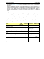
Register Values Table
The table within the window shows the registers and their initialization value, displayed in the column Init. value
. This value written into the register or bit by the generated code during the initialization process of the
application. It is the last value that is written by the initialization function to the register. The After reset column
contains the value that is in the register by default after the reset.
The values of the registers are displayed in the hexadecimal and binary form. In case the value of the register (or
bit) is not defined, an interrogation mark "?" is displayed instead of the value.
Note: For some registers, the value read from the register afterwards can be different than the last written value.
For example, some interrupt flags are cleared by writing 1. Please see the MCU manual for details on registers
behavior.
In case the peripheral is allocated by a component and the setting of the component is incorrect, the initialization
values are not displayed in the Configuration Registers window.
- 32 -
Processor Expert User Manual
Application Design
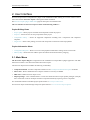
3. Application Design
This chapter will hep you to design application using Processor Expert and Embedded Components. You will
find here recommendations and solutions to write and optimize a code effectively. If you are a beginner, please
see the section Quick start that shows how to generate the code of your first project.
The following subchapters explain:
• Quick Start in Processor Expert
• Basic Principles
• Configuring Components
• Implementation Details
• Code Generation and Usage
• Embedded Component Optimizations
• Converting Project to Use Processor Expert
• Low-level Access to Peripherals
• Processor Expert Files and Directories
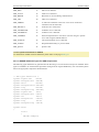
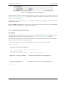
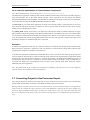
3.1. Quick Start in Processor Expert
Step 1 - Open an example
You can start learning Processor Expert by opening one of the available examples. Use the command File >
Import... to open the Import dialog. Then select General / Existing Projects into Workspace and click Next
button. All Processor Expert examples can be found within the folder {CodeWarrior_for_MCUs}
\MCU\CodeWarrior_Examples\Processor_Expert. Use the Browse button and select the directory
of the example project that you would like to use under this folder. Click on the Finish button.
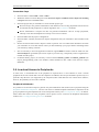
Step 2 - Code generation
After opening an example, invoke the code generation of the project to obtain all sources. In the project tree,
right-click the ProcessorExpert.pe file and select the Generate Processor Expert Code command. The
generated code is placed in the Generated_Code sub-folder of the project.
Step 3 - More Complicated Example
Once you have learned the basic skills, you can open a more complicated example in order to get to more
advanced level of code generation.
Creating Own Projects
See the chapter 4 Processor Expert Tutorials for step-by-step tutorials on creating Processor Expert projects
from the beginning.
- 33 -
Processor Expert User Manual
Application Design
3.2. Basic Principles
The application created in Processor Expert is built from the building blocks called Embedded Components. The
following sub-chapters describe the features of the Embedded Components and the CPU components that are
special type of Embedded Components and what they offer to the user.
• Embedded Components
• CPU Components
3.2.1. Embedded Components
Embedded components encapsulate the initialization and functionality of embedded systems basic elements,
such as MCU core, on-chip peripherals (for details on categories of components delivered with Processor Expert
see chapter 3.2.1.1 Component Categories), FPGAs, standalone peripherals, virtual devices, and pure software
algorithms.
These facilities are interfaced to the user through properties, methods and events. It is very similar to objects in
the Object Oriented Programming (OOP) concept.
Easy Initialization
A user can initialize components by setting their initialization properties in the Component Inspector. Processor
Expert generates the initialization code for the peripherals according to the properties of the appropriate
components. User can decide whether the component will be initialized automatically at startup or manually by
calling the component's Init method.
Easy On-chip Peripherals Management
Processor Expert knows exactly the relation between the allocated peripherals and the selected components.
When the user selects a peripheral in the component properties, Processor Expert proposes all the possible
candidates but signals which peripherals are allocated already (with the icon of the component allocating the
peripheral). PE also signalizes peripherals that are not compatible with the current component settings (with a
red exclamation mark). In the case of an unrealizable allocation, an error is generated.
Unlike common libraries, Embedded Components are implemented for all possible peripherals, with optimal
code. The most important advantages of the generated modules for driving peripherals are that you can:
• Select any peripheral that supports component function and change it whenever you want during design time.
• Be sure that the component setting conforms to peripheral parameters.
• Choose the initialization state of the component.
• Choose which methods you want to use in your code and which event you want to handle.
• Use several components of the same type with optimal code for each component.
The concept of the peripheral allocation generally does not enable sharing of peripherals because it would make
the application design too complicated. The only way to share resources is through the components and their
methods and events. For example, it is possible to use the RTIshared component for sharing periodic interrupt
from timers.
- 34 -
Processor Expert User Manual
Application Design
Methods
Methods are interfacing component functionality to user's code. All enabled methods are generated into
appropriate component modules during the code generation process. All Methods of each component inserted
into the project are visible as a subtree of the components in the Project panel.
You can use in your code all enabled methods. The easiest way to call any method from your code is to drag and
drop the method from project panel to the editor. The complexity and number of methods depend on the
component's level of abstraction.
Events
Some components allow handling the hardware or software events related to the component. The user can
specify the name on function invoked in the case of event occurrence. They are usually invoked from the internal
interrupt service routines generated by Processor Expert. If the enabled event handling routine is not already
present in the event module then the header and implementation files are updated and an "empty" function
(without any code) is inserted. The user can write event handling code into this procedure and this code will not
be changed during the next code generation.
All Methods and Events of each component inserted into the project are visible as a subtree of components in the
Project panel.
Interrupt Subroutines
Some components, especially the Low-level components and the Peripheral Initialization components ( please
see more details in chapter 3.2.1.1 Component Categories ) allow to assign an interrupt service routine (ISR)
name to a specific interrupt vector setup.
The name of the Interrupt service is generated directly to the interrupt vector table and the user has to do all
necessary control registers handling within the user code. See 3.5.3.1 Typical Usage of Peripheral Initialization
Components for details.
ISRs items are listed in the subtree of a component in the Project panel.
Figure 3.1 - Example Of a Component With Two ISRs
Highly Configurable and Extensible Library
Embedded Components can be created and edited manually or with the help of Component Wizard. CPU
Components are a special category of components.
- 35 -
Processor Expert User Manual
Application Design
3.2.1.1. Component Categories
Components Library Categories
Complete list of the component categories and corresponding components can be found in the Component
Categories page of the Components Library
The components are categorized based on their functionality, so you can find an appropriate component for a
desired function in the appropriate category.
There are the following main categories, which further contain various sub-categories.
• CPU External Devices - Components for devices externally controlled to the CPU. For example sensors,
memories, displays or EVM equipment.
• CPU Internal Peripherals - Components using any of on-chip peripherals offered by the CPU. The
Components Library folder with the same name contains sub-folders for the specific groups of functionality.
(i.e. Converters, Timers, PortIO etc.)
Note: It seems that components (especially in this category) correspond to on-chip peripherals. Even this
declaration is close to the true, the main purpose of the component is providing the same interface and
functionality for all supported MCU s. This portability is the reason why the component interface often
doesn't copy all features of the specific peripheral.
• Logical Device Drivers - LDD components. See 3.2.1.2 Logical Device Drivers for details.
• Operating systems - Components related to Processor Expert interaction with operating system running on
the target.
• SW - Components encapsulating a pure software algorithms or inheriting a hardware-dependent components
for accessing peripherals. These components (along with components created by the user) can be found in a
components library in the folder 'SW'.
Specific functionality of the MCU may be supported as a version-specific settings of the component. For more
information about this feature please refer to Version specific parts in the component documentation or
Components Implementation help chapter.
Levels of Abstraction
Processor Expert provides components with several levels of abstraction and configuration comfort.
• LDD components - Logical Device Drivers. The LDD components are efficient set of components that are
ready to be used together with RTOS. They provide a unified hardware access across MCUs allowing to
develop simpler and more portable RTOS drivers or bare board application. See 3.2.1.2 Logical Device
Drivers for details.
• High Level Components - Components that are the basic set of components designed carefully to provide
functionality to most microcontrollers in market. An application built from these components can be easily
ported to another microcontroller supported by the Processor Expert. This basic set contains for example
components for simple I/O operations (BitIO, BitsIO, ByteIO, ...), timers (EventCounter, TimerInt, FreeCntr,
TimerOut, PWM, PPG, Capture, WatchDog,...), communication (AsynchroSerial, SynchroMaster,
SynchroSlave, AsynchroMaster, AsynchroSlave, IIC), ADC, internal memories.
This group of components allows comfortable settings of a desired functionality such as time in ms or
frequency in Hz without user knowing about the details of the hardware registers. MCU specific features are
supported only as CPU specific settings or methods and are not portable.
- 36 -
Processor Expert User Manual
Application Design
The components inheriting or sharing a high-level component(s) to access hardware are also high-level
components.
• Low Level Components - Components that are dependent on the peripheral structure to allow the user to
benefit from the non-standard features of a peripheral. The level of portability is decreased due to a different
component interface and the component is usually implemented only for a MCU family offering the
appropriate peripheral. However, you can easily set device features and use effective set of methods and
events.
• Peripheral Initialization Components - Components that are on the lowest level of abstraction. An
interface of such components is based on the set of peripheral control registers. These components cover all
features of the peripherals and are designed for initialization of these peripherals. Usually contain only "Init"
method, see 3.5.3.1 Typical Usage of Peripheral Initialization Components for further details). The rest of
the function has to be implemented using a low level access to the peripheral. This kind of components could
be found in the " CPU Internal Peripherals / Peripheral Initialization Components " folder of the
Components library and they are available only for some CPU families. The interface of these components
might be different for a different CPU. The name of these components starts with the prefix 'Init_'.
Features of Components at Different Level of Abstraction
Feature
LDD
components
High level
Low level
Peripheral Init
High-level settings portable between
different MCU families
partially
yes
partially
no
Portable method interface for all CPU
families
yes
yes
partially
Init method only
(usually direct access to
control registers)
CPU specific peripheral features support
mostly yes
partially
mostly yes
full
partially
no
partially
yes
Speed mode independent timing
yes
yes
mostly yes
no
Events support
yes
yes
yes
Low-level peripheral initialization
settings
no
(direct interrupt
handling)
Software emulation of a component
function (if the specific hardware is not
present)
no
yes
no
no
Support for RTOS drivers creation
yes
no
no
no
- 37 -
Processor Expert User Manual
Application Design
3.2.1.2. Logical Device Drivers
Introduction
Logical Device Drivers were developed to offer users the Hardware Abstraction Layer (HAL) for bare-metal
applications as well as RTOS applications. The components provide tested, optimized C code tuned to the
application needs. The code may be tuned to the specific RTOS when the RTOS component is in the project.
Differences between LDD and High Level Components
• Each component provides Init() method to initialize appropriate peripheral and driver. Init() method returns
a pointer to driver’s device structure.
• Each component provides Deinit() method to de-initialize appropriate peripheral and driver.
• The first parameter of each component’s method is a pointer to a device structure returned from Init()
method. It is up to the user to pass a valid device structure pointer to component’s methods (null check is
highly recommended).
• The Init() method has one parameter UserDataPtr. A user can pass a pointer to its own data and this pointer
is then returned back as a parameter in component’s events. The pointer or date pointed by this pointer is not
modified by driver itself. A bare-board application typically passes a null pointer to Init() method.
• LDD components are not automatically initialized in CPU component by default. If 'Auto initialization'
property is not enabled, a user must call appropriate Init() method during runtime. Othervise the Init method
is automatically called in CPU component and device structure is automatically defined.
• LDD components have RTOS adapter support allowing to generate variable code for different RTOSes.
• Runtime enable/disable of component events.
• Low Power Modes support.
Logical Device Drivers in Bare-metal Applications
Logical Device Drivers can be used in applications where the RTOS is not required.
Logical Device Drivers in bare-metal environment have following specific features:
• Init() method of each component uses a static memory allocation of its device structure.
• Interrupt Service Routines are statically allocated in generated interrupt vector table (IVT).
• The Linker Command File (LCF) is generated from CPU component.
• The main module (ProcessorExpert.c) is generated.
Logical Device Drivers in RTOS environment
Logical Device Drivers in RTOS environment have following specific features:
• Init() method of each component uses a dynamic allocation of its device structure through the RTOS API.
• Deinit() method of each component uses a dynamic de-allocation of its device structure through the RTOS
API.
• Interrupt Service Routines are allocated through the RTOS API in Init() method and de-allocated in Deinit()
method of each component.
• The Interrupt table is not generated from CPU component in case whether RTOS provides runtime allocation
of interrupt service routines.
• The Linker Command File (LCF) is not generated from CPU component in case that RTOS provides its own
- 38 -
Processor Expert User Manual
Application Design
LCF for applications.
• The main module (ProcessorExpert.c) is not generated if specified in RTOS adapter.
For information and hints on LDD components usage, please see the section 3.5.3.2 Typical LDD Components
Usage.
RTOS adapter
The RTOS adapter component is a way how to utilize generated code to the specific RTOS. The RTOS adapter
provides necessary information to the driver which API should be used to allocate memory, create a critical
section, allocate interrupt vector, etc.
Figure 3.2 - Example of HAL integration into existing RTOS
Shared Drivers
Logical device drivers support the shared mode that means that more components can be put together to provide
one instance of API. The user can access each component instance through the API of the shared component. A
driver device data structure is used for resolution which peripheral instance shall be accessed. Currently there are
three components that support shared mode: Serial_LDD, CAN_LDD and Ethernet_LDD.
- 39 -
Processor Expert User Manual
Application Design
Low Power Features
Logical device drivers in conjunction with CPU component implement low power features of a target MCU .
Each LDD component define two methods related to the low power capability – SetOperationMode() and
GetDriverState(). For more details see documentation of components.
Figure 3.3 - Usage of low power API in Logical Device Drivers
In the example above, DPM (Dynamic Power Manager) task may opt to care for a selected number of
peripherals for graceful power mode change (eg. FEC, CAN) and rest of the peripheral drivers need not know
the power mode change. When opted for informing a peripheral device driver, the DPM can build a semaphore
object for low power acknowledgement from the device drivers. When all such acknowledgements arrive (ie.
Semaphore count equals zero) the CPU can be placed into a wait/sleep power mode. In the future, with silicon
design modifications, these semaphores can be implemented in the hardware and as a result a much faster power
mode change can be expected. In There is no DPM in typical bare-metal applications the DPM task is
implemented. In this case DPM is substituted by a user application code.
- 40 -
Processor Expert User Manual
Application Design
3.2.2. CPU Components
A CPU component is an Embedded Component encapsulating one processor type. A Processor Expert project
may contain one or more CPU components. The project generated for one CPU is called an Application.
Processors included in a project are displayed in the upper part of the Project panel (depending on the Project
panel settings). It's possible to switch among the CPU component, but only one of the CPU can be active at one
time.
The Build options accessible in the Component Inspector of the CPU component allow the user to set
properties of the Compiler and Debugger (if it is supported).
Portability
• It is possible to change the target MCU during the development of an application and even to switch between
multiple MCUs. This can be done simply by adding another CPU to the project and selecting it as the target
CPU.
• To connect the new CPU peripherals to the application components correctly, it is possible to specify the
CPU on-chip peripheral names. This way the same peripheral could be used on different CPU derivatives
even if the original name is different.
Adding a CPU to a Project.
1.
In the Components Library window, select the CPU tab and find the desired CPU component.
2.
Double-click the desired CPU icon to add it to the project. When the CPU component is added, it appears
in the upper part of the Project panel. If selected as the target CPU, the processor will be displayed in the
Target CPU window.
Selecting a CPU as Target CPU
The first MCU added to the project is automatically selected as the target CPU . It means that code will be
generated for this MCU. When there are more than one CPU in the project, the target CPU can be changed by
following these steps:
1.
Right-click the CPU icon in the Project panel to display a pop-up menu.
2.
Select Select CPU as target - the CPU is selected as target.
This setting doesn't affect the setting of the target in the Targets tab in the CodeWarrior project panel. If the user
changes the target CPU in the Processor Expert project panel and the CPU doesn't match with the current
CodeWarrior target settings, the Linker dialog box is invoked during the code generation allowing the user to
update the linker setup.
- 41 -
Processor Expert User Manual
Application Design
Changing Settings
To modify the CPU component settings (its properties, methods, events, external bus, timing, user-reserved
peripherals, compiler and debugger settings etc.) is to invoke the Inspector for the selected CPU component.
If you have added CPU to your project, you can invoke Component Inspector by performing either of the
following:
• Right click the CPU icon in the Project panel to display pop-up menu and select the CPU inspector.
• Double-click the CPU icon in the Project panel.
For a detailed description of the current CPU properties, methods and events, select Help on Component
command in the View menu (drop-down arrow) in the Component Inspector.
3.2.2.1. CPU component variants selection
This dialog is shown during the creation of a new project using Project Wizard or when the user adds a new CPU
component into project using Components Library view.
In this dialog the user can select CPU pin-variants and configurations that will be supported for switching later in
the project. Each selection of variant or configuration represent one CPU component pre-set. For example, if the
user selects two pin variants and two configuration, there will be totally four CPU components added into the
project. For details on configurations, please see 3.3.2 Configurations.
- 42 -
Processor Expert User Manual
Application Design
3.2.2.2. Compiler selection
This dialog is shown when the user adds a new CPU component into project using Components Library view.
If there are more target compilers available, the user can select the compiler to be userd for the newly added CPU
.
3.2.2.3. CPU Properties Overview
CPU Properties can be set in CPU Component Inspector. The complete list of CPU properties and their
description is available in the help page for the CPU. To open the CPU help page, select Help > Help on
Component from the menu bar in the Component Inspector window.
Following properties define the basic settings of the CPU:
• CPU type
• External Xtal frequency (and sub-clock xtal frequency)
• PLL settings
• Initialization interrupt priority
• External bus and signals
• Speed modes (See the following chapter Speed Modes).
• All other functions that are not directly encapsulated by components
- 43 -
Processor Expert User Manual
Application Design
3.2.2.4. Speed Modes Support
Note: Speed Modes are not available for Kinetis and ColdFire+ family MCUs. Please use the Clock
configurations instead.
The CPU component supports up to three different speed modes. The three speed modes is a Processor Expert
specific concept which (among all the other PE features and concepts) ensures the portability of the PE projects
between different CPU models.
In fact, the three speed modes are a generalization of all the possible CPU clock speed modes used for
power-saving that can be found in most of the modern microcontrollers. In the area of embedded systems, power
saving and power management functions are so important that we could not neglect the proper HW- independent
software implementation of these functions.
Therefore, for keeping the portability (HW independence) of PE projects, we recommend not to program the
CPU speed functions manually, but use these three CPU Component speed modes instead:
• High speed mode - this mode is selected after reset and must be enabled in the project. This speed mode
must be the fastest mode of the main CPU clock.
• Low speed mode - this mode is usually used for another PLL or main prescaler settings of the main CPU
clock.
• Slow speed mode - this mode is usually used for the slowest possible mode of the main CPU clock.
Switching Speed Modes at Runtime
The modes can be switched in the runtime by the following CPU component methods:
• SetHighSpeed
• SetLowSpeed
• SetSlowSpeed
If a speed mode is enabled in the CPU Component properties, the corresponding method is enabled
automatically.
It is highly recommended to disable interrupts before switching to another speed mode and enable them
afterwards.
Speed Modes Support in Components
Using the component property CPU clock/speed selection, it is possible to define the speed modes supported by
the component.
Some components allow to set two values of the CPU clock/speed selection property:
• Supported - The CPU clock/speed selection group contains properties defining which speed modes are
supported for the component.
• Ignored - The speed mode settings are ignored and there are no action is performed when a speed mode is
changed, that is the peripheral continues to run with the same configuration for all speed modes. No speed
mode handling code is generated for this component. The component timing values are valid only for
high-speed mode.
The following features are available for high-level components, if the CPU clock/speed selection is not set to
ignored:
- 44 -
Processor Expert User Manual
Application Design
• During the design, all the timing-related settings for such a component are checked to be correct in all the
speed modes that the component supports and the component is enabled in these modes.
• If the speed mode is changed, the current timing components are preserved (recalculated to be the same in
the new speed mode), except the timing that is set at runtime from interval.
If the CPU speed mode is changed to a mode that the component does not support for any reason, the
component is disabled right after the CPU speed mode is changed. Otherwise the component is enabled.
• Before or after the speed mode is changed, the BeforeNewSpeed and AfterNewSpeed event functions are
called.
3.3. Configuring Components
Configuring the components in the project is one of the main activities in Processor Expert. It affects the
initialization, run-time behavior and range of functionality available to the user of the generated code. For the
description of the user interface of the components settings please see the chapters 2.2 Project Panel View and
2.4.3 Component Inspector.
The following sub-chapters provide hints and information about how to configure the Embedded Components
used in the project correctly and effectively.
• Interrupts and Events
• Configurations
• Design Time Checking: Consequences and Benefits
• Timing Settings
• Creating User Component Templates
• Signal Names
• Component Inheritance and Component Sharing
• Pin Sharing
3.3.1. Interrupts and Events
This chapter describes the details of interrupt and events processing in the code generated by Processor Expert.
An Interrupt is a signal that causes the CPU stop the execution of the code and execute the Interrupt service
routine instead. When the execution of the code is suspended, the current state of the CPU core is saved on the
stack. After the execution finishes, the previous state of the CPU core is restored from the stack and the
suspended program continues from the point where it was interrupted. The signals causing interrupts can be
hardware events or software commands. For more details, please see an appropriate CPU manual.
Each interrupt can have an assigned Interrupt Service Routine (ISR) that is called when the interrupt occurs.
The table assigning the subroutines to interrupts is called Interrupt Vector Table and it is completely generated
by Processor Expert. Most of the interrupts have corresponding Processor Expert Events that allow handling of
these interrupts. Processor Expert also allows to configure interrupt priorities, if they are supported by the CPU.
See 3.3.1.1 Processor Expert Priority System for details.
Processor Expert Events are part of the Embedded component interface and encapsulate the hardware or
software events within the system. Events are offered by the High and Low Level components to help the user to
service the events without any knowledge of the platform specific code required for such service.
- 45 -
Processor Expert User Manual
Application Design
Processor Expert Events can be enabled and disabled and have a user-written program subroutines that are
invoked when the event occurs. Events often correspond to interrupts and are for that case invoked from the
generated ISR. Moreover, the event can also be a pure software event caused by a buffer overflow or improper
method parameter.
Interrupts Usage in Component's Generated Code
Some high-level components use interrupt service routines to provide their functionality. Usage of interrupts can
usually be enabled/disabled through property "Interrupt service/event". If the interrupt service is used, complete
interrupt service routine is generated into component's driver and the generated code contains configuration of
the corresponding peripheral to invoke the interrupts.
The user should be careful while disabling an interrupt. If a component should operate properly, it is necessary to
allow the interrupt invocation by having interrupts enabled and (if the CPU contains priority system) set the
corresponding interrupt priority level. This can be done using the appropriate method of the CPU component.
Note: It is a common "bug" in user code, if the application is a waiting for a result of the component action
while the interrupts are disabled. In this situation, the result of the component method does not change until the
interrupt service routine is handled. See description of the property "Interrupt service/event" for detailed
information about the particular component.
Enabling Event
Functionality of each event can be enabled or disabled. The user can easily enable the event and define its name
within the Component Inspector of the appropriate component. Another possibility is to double-click an event
icon in the component's subtree or use a pop-up menu in the Project Panel window.
Figure 3.6 - Event Example in the Component Inspector Events Tab
Writing an Event Handler
Event handler is a subroutine that is assigned to a specific event. After the event is enabled Processor Expert
generates the empty function of the specified name to the Event module. See 3.5.1 Code Generation for details.
The user can directly open the Event handler code (if it already exists) using a Component pop-up menu >
View/Edit event module or a double-click on the event within the Project Panel. The event handler is an
ordinary function and the user needs not to provide the interrupt handling specific code in his/her event code.
- 46 -
Processor Expert User Manual
Application Design
Interrupt Service Routines
When High or Low-level components are used, the interrupts functionality is covered by the events of the
components. The interrupt subroutines calling the user's event handlers are generated to the component modules
and PE provides parts of the background code necessary to correctly handle the interrupt requests.
The Peripheral Initialization components can only provide the initialization of the interrupt and generate a
record to the Interrupt Vector Table. The user has to provide a full implementation of the interrupt subroutine.
See 3.5.3.1 Typical Usage of Peripheral Initialization Components for details.
3.3.1.1. Processor Expert Priority System
Some CPUs support selectable interrupts priorities . The user may select a priority for each interrupt vector.
The interrupt with a higher priority number can interrupt a service routine with the lower one.
Processor Expert supports the following settings in design-time: interrupt priority and priority of the event code.
Priority can also be changed in the user code. The user may use a CPU component method to adjust the priority
to a requested value.
Interrupt Priority
The user may select interrupt priority in the component properties, just below the interrupt vector name.
Processor Expert offers the following values, which are supported for all microcontrollers:
• minimum priority
• low priority
• medium priority
• high priority
• maximum priority
The selected value is automatically mapped to the priority supported by the target microcontroller. It is indicated
in the third column of the Component Inspector.
The user may also select a target-specific numeric value (such as priority 255), if portability of the application to
another architecture is not required.
Peripheral Initialization components on some platforms also allow to set the value default that means that the
user doesn't have any requirement on it so the priority value will be the default after-reset value.
Version specific information for HCS08 derivatives with IPC (Interrupt Priority Controller)
The HCS08 derivatives with IPC module offer an interrupt priority configuration. There are four interrupt
priority levels 0 to 3 available, where 0 is the lowest priority and 3 is the highest one.
The platform-independent interrupt priority values in Processor Expert described on top of this section are
mapped to these values.
Version specific information for RS08 without interrupt support and HC(S)08 derivatives without IPC
(Interrupt Priority Controller)
These derivatives do not support interrupt priorities. The interrupt priority settings, for example imported from
a project for another CPU, are ignored.
- 47 -
Processor Expert User Manual
Application Design
Version specific information for RS08 with interrupt support
On these RS08 derivatives, the interrupts are handled through single interrupt vector. The priority of each
individual "emulated interrupt" is determined by order in which the SIPx registers are polled in the sofware
handler. The priority can be in the range 0 ..number_of_interrupts-1 (e.g. 0 .. 15). The lower is the number the
higher is the priority. The platform independent interrupt priority values in Processor Expert described on top
of this section are mapped to these values.
The default priority depends on the position of an associated bit in a SIPx register. The interrupt priority can be
changed to any value within the allowed range. Interrupts with lower priority number (higher priority of
execution) are polled first. If two interrupts have assigned the same priority number then the order in which
they are polled depends on the default priority. For more details on interrupts on RS08 please see the chapter
Version Specific Information for RS08.
Version specific information for ColdFire V1 derivatives
On the ColdFire V1 platform, an interrupt priority of an interrupt is determined by an Interrupt Level (1-7) and
a Priority within Level (0-7). Please see the CPU data sheet for interrupt priority system details.
The applied interrupt priority value (the value displayed in the third column of the Component Inspector )
contains both values - e.g. Level 4, priority within level 6. The target-independent values of interrupt priority
(e.g. minimum, maximum etc...) are mapped either to the default priority of the selected interrupt or to Level 6,
Priority within level 6 or level 6, Priority within level 7.
Priority of Event Code
Version specific information for Kinetis and ColdFire+ derivatives
Priority of event code is not supported for Kinetis and ColdFire+.
The user can also select a priority for the processing of the event code. This setting is available for the events
that are invoked from the Interrupt Service Routines. This priority may be different from the interrupt priority.
However, the meaning of the number is the same - the event may be interrupted only by the interrupts with the
higher priority. Processor Expert offers the following architecture independent values:
• same as interrupt - default value which means that Processor Expert doesn't generate any code affecting the
priority of the event - the priority is in the state determined by the default hardware behavior.
• minimum priority
• low priority
• medium priority
• high priority
• maximum priority
• interrupts disabled - For example the highest priority supported by the microcontroller, which may be
interrupted only by non-maskable interrupts.
The selected value is automatically mapped to the priority supported by the target microcontroller and the
selected value is displayed in the third column of the Component Inspector.
Please see version specific information below. The user may also select a target-specific value, if portability of
the application to another architecture is not required.
Note: Some events do not support priorities, because their invocation is not caused by the interrupt processing.
- 48 -
Processor Expert User Manual
Application Design
Warning: Please note that Processor Expert does not allow the user decrease an event code priority (with the
exception of 'Interrupts enabled' value on some platforms, please see below). This is because Processor Expert
event routines are not generally reentrant so there is a risk that the interrupt would be able to interrupt itself
during the processing. If there is such functionality requested, the user has to do it manually (e.g. by calling a
appropriate CPU component method setting a priority) and carefully check possible problems.
Version specific information for HCS08 derivatives with IPC (Interrupt Priority Controller)
Processor Expert offers the following event priority options:
• interrupts enabled - Interrupts are enabled and the priority of the event routine stays at the same level as
the interrupt. The interrupts with the higher priority than the current interrupt priority can interrupt the
event code.
• interrupts disabled - All maskable interrupts are disabled.
• 1..3 - Priorities from lowest (1) to highest (3). The code generated by Processor Expert before the event
invocation sets the event code priority to the specified value.
• 4 - Same as 'interrupts disabled'
• same as interrupt - Default behavior of the architecture - no interrupts can interrupt the event. It is same as
interrupts disabled.
• Other values are mapped to the priorities 1..4.
Version specific information for HC(S)08 derivatives without IPC (Interrupt Priority Controller)
Processor Expert offers the following event priority options:
• interrupts disabled - All maskable interrupts are disabled.
• interrupts enabled - All maskable interrupts are enabled. Please note that this settings might lead to
possible problems, see the warning within this chapter.
• same as interrupt - Default behavior of the architecture - no interrupts can interrupt the event. It is same as
"interrupts disabled".
Version specific information for RS08 with interrupt support
Because of architecture limitations, the Processor Expert allows only interrupts disabled value so the interrupt
is always disabled within the event routines. The same as interrupt value is mapped to interrupts disabled.
Version specific information for ColdFire V1 derivatives
Processor Expert offers the following event priority options:
• interrupts disabled - All maskable interrupts are disabled within the event routine.
• 0..7 - Priorities from the lowest (0) to the highest (7). The code generated by Processor Expert before the
event invocation sets interrupt priority mask to the specified value. The event routine may be then
interrupted only by an interrupt with higher priority than the specified number.
• same as interrupt - The priority of the event routine stays on the level set for the interrupt. The event
routine can be interrupted only by a higher priority interrupt then the value set for the interrupt.
- 49 -
Processor Expert User Manual
Application Design
Version specific information for 56800 derivatives
Processor Expert offers the following event priority options:
• interrupts enabled - Interrupts are enabled so the event routine can be interrupted by another interrupt.
Please note that this settings might lead to possible problems, see the warning within this chapter.
• interrupts disabled - All maskable interrupts are disabled.
• same as interrupt - Default behavior of the architecture within interrupts service routines - interrupts are
disabled.
Version specific information for 56800E derivatives
Processor Expert offers the following event priority options:
• interrupts disabled - All maskable interrupts are disabled within the event routine.
• 1..3 - Priorities from the lowest (1) to the highest (3). The code generated by Processor Expert before the
event invocation sets the event code priority to the specified value. The event routine can be interrupted
only by a higher priority interrupt than the specified number.
• same as interrupt - The priority of the event routine stays on the level set for the interrupt. The event
routine can be interrupted only by a higher priority interrupt then the value set for the interrupt.
• Other values are mapped to the priorities 1..3.
3.3.2. Configurations
The user can have several configurations of the project in one project file. The configuration system is very
simple. Every configuration keeps the enable/disable state of all components in the project (it does NOT keep
any component settings!). If you enable/disable a component in the project, the component state is updated in the
currently selected configuration. If you create a new configuration the current project state is memorized.
Configurations of the current project are listed in the Project Panel configurations folder.
Configurations can also hold additional settings that may influence code generation. These settings can be
changed in the configuration inspector. See 2.4.4 Configuration Inspector for details.
The symbol for conditional compilation is defined if it is supported by the selected language/compiler. The
symbol PEcfg_[ConfigurationName] is defined in the CPU interface.
The user can switch using this symbol between variants of code according to the active configuration (see
example in this chapter).
Configuration also stores which CPU is selected as the target CPU.
If the name of the configuration matches the name of one of the CodeWarrior's targets, the target is
automatically selected as an active target when the user runs code generation.
Note: It is possible to have two components with the same name in Project. Each of the components could be
enabled in different configuration. This way the user can have different setup of a component (a component with
the same name) in multiple configurations.
- 50 -
Processor Expert User Manual
Application Design
Example
Suppose, there is a configuration named 'Testing case'. We use a component and part of our code using the
component only in the 'Testing case' configuration. Then we make the testing case configuration active. After the
successful code generation the CPU.H file contains the following definition:
/* Active configuration define symbol */
#define PEcfg_Testingcase 1
The parts of the code intended to be used only in this configuration need to be surrounded with the following
lines:
...
#ifdef PEcfg_TestingCase
Component_MethodCall(...);
#endif
...
3.3.3. Design Time Checking: Consequences and Benefits
During the design time, Processor Expert performs instant checking of the project. As a result of this
checking, error messages may appear in the Problems View or directly in the third column of the Component
Inspector (on the faulty items line). Sometimes, it may happen that only one small change in the project causes
several (general) error messages.
On-Chip Peripherals
Some components use on-chip peripherals. In the Component Inspector, you can choose from all possible
peripherals that can be used for implementation of the function of the current component. Processor Expert
provides checking for required peripheral features such as word width and stop bit for serial channel, pull
resistor for I/O pin and others.
Processor Expert also protects against the use of one peripheral in two components. If the peripheral is allocated
for one component then the settings of this peripheral cannot be changed by any other component. The state of
an allocated peripheral should never be changed directly in the user code. (Using special registers, I/O
ports etc.) It is recommended to always use methods generated by Processor Expert. If the functionality of
generated methods is not sufficient for your application, you can use PESL (Processor Expert System Library).
See 3.8 Low-level Access to Peripherals for details.
Note that if a peripheral is allocated to any component, all its parts are reserved. For example if you use the
8-bit I/O port, all the I/O pins of the port are allocated and it is not possible to use them in other components.
In some timer components you can choose if you want to use only a part of the timer (compare register) or an
entire timer. If you select the entire timer, the driver can be optimized to work best with the timer. It can, for
example, invoke reset of the timer whenever is it needed by the component function.
- 51 -
Processor Expert User Manual
Application Design
Interrupt Priority
If the target CPU shares interrupt priority between several interrupt vectors or shares interrupt vectors, Processor
Expert provides checking of interrupt priority settings. For detailed information about Interrupt Priority see the
Priorities page.
Memory
Processor Expert always checks the usage of the internal and external memories accessible throught CPU
address and data bus. Position and size of internal memory is defined by the CPU type and can be configured in
the CPU Properties (if supported). External memories must be defined in CPU Properties.
Any component can allocate a specified type of memory. See component descriptions for detailed information
about requirements for types of memory. Processor Expert provides checking of memory and protects you from
making a wrong choice. ( For example: if a component requires external Flash, it is not possible to enter an
address in internal RAM).
The bits can also allocate memory. Therefore, you can be sure that only one component uses an allocated bit of a
register in external address space.
Timing
The settings of all timed high-level components are checked using the internal timing model. See 3.3.4 Timing
Settings for details. If there is no error reported, it means that Processor Expert was successful in calculating the
initialization and runtime control values for all components and hence the settings should work according to the
configuration.
3.3.4. Timing Settings
Many high-level components contain a timing configuration (e.g. speed of the serial communication, period of
the interrupt, conversion time of the ADC etc.). Processor Expert allows to configure such timing using
user-friendly units and it also contains a model of the complete MCU timing. This model allows calculation of
the required values of control registers and continuous validation of the timing settings.
Timing Model
A component timing can be viewed like a chain of elements, such as dividers and multipliers between the main
clock source and the device configured by the component. The user sets the desired timing value using the
Timing Dialog box (see chapter 2.4.3.1 Dialog Box for Timing Settings) or directly by specifying the value in
Component Inspector (see chapter 2.4.3.2 Syntax for the Timing Setup in the Component Inspector). Processor
Expert tries to configure individual elements in the timing chain to achieve the result and the user is informed if
it was successful. After leaving the Timing Dialog box, the real value of the timing is shown in the third column
of the component inspector.
- 52 -
Processor Expert User Manual
Application Design
Timing Setup Problems
The errors are reported in red in the Timing Dialog box or in the timing property line in the Component
Inspector. The error summary is available in the Error window. Please follow the error message text to find the
source of the problem. If no error is reported, it means that Processor Expert can achieve the desired timing for
all components in the project.
Common problems that make impossible to set a timing value:
• It is impossible to set some item(s).
This problem is reported in the component or the Timing dialog box and the user is informed which value
has incorrect value. The reason is usually the hardware structure and limitations of the CPU. The Timing
dialog box shows the list of values (ranges) that are allowed to be set. It might be necessary to increase the
allowed error (using the 'Error' field in the Timing Dialog) that specifies the allowed difference between the
required value and possible value that can be produced by the hardware.
• Settings for the device are mutually incompatible (or can't be used with another device).
In this case, the problem is reported by all components that share some timing hardware. Due to
dependencies between used parts of the timer, there might be necessary to adjust the values of the shared
elements (such as prescalers) to the same value.
For example, if two TimerInt components are using two channels of one timer and all timer channels are
connected to one common prescaler, it is not possible to set the values that would require a different
prescaler values. In this case it is useful to manually adjust the prescaler values of all components to the same
value (switch to Expert view mode and adjust the property in the Component Inspector window).
• The Runtime setting from interval is selected and it is not possible to set the values.
The required run-time settings are outside the range of one prescaler. This is a limitation of this mode of
runtime setting. Please see the text below in this chapter.
Run-time Timing Settings Limitation
Some components allow to change the timing at run-time by switching among several predefined values or by
setting a value from given interval.
For the runtime setting from interval the prescaler value is fixed and the Processor Expert allows to adjust the
time using a compare/reload registers. It means that Processor Expert allows to configure the limits of an
interval only within a range of one prescaler and it's possible to set values from this interval only. See
2.4.3.1 Dialog Box for Timing Settings for details.
Speed Modes
Processor Expert provides three speed modes that are generalization of all the possible CPU clock speed modes
used for power-saving supported by most of the modern microcontrollers. See 3.2.2.4 Speed Modes Support for
details.
- 53 -
Processor Expert User Manual
Application Design
3.3.5. Creating User Component Templates
If you frequently use a component with the same specific settings, you may need to save the component with
its settings as a template. This template is displayed in the Components library under given name, behaves as a
normal component and could be added to any project. The template has the same properties as the original
component. The values of the properties are preset in the template and could be marked as read only.
This section describes how to create a component template and save it.
Creating and Saving Templates
1.
Open the pop-up menu of the component in the Project Panel and select Save component settings as
template.
Alternatively, you can use the Component Inspector window: open the view menu using the arrow icon
in the top right corner and select Save component settings as template.
2.
Fill in the template details into the dialog box and confirm:
3.
The template appears within the Components Library and can be inserted into projects. It may be
necessary to invoke refresh command by selecting the Components Library pop-up menu > Refresh.
- 54 -
Processor Expert User Manual
Application Design
3.3.6. Signal Names
The main purpose of signals is to allow the user to name the pins used by components with names corresponding
to the application.
Assigning Signals to Pins
A signal name can be assigned to an allocated pin by specifying the signal name into the appropriate property
(e.g. Pin_signal) in the Component Properties (available in ADVANCED view mode). Signal name is an
identifier that must start with a letter and rest of the name must contain only letters, numbers, and
underscore characters.
For the components that allocate a whole port, such as ByteIO, there are two options:
• Assign a same signal name to all pins of port by writing the name into the Port signal property. Processor
Expert automatically assigns this name extended with a bit number suffix to each of the individual pins.
• Assign a different signal names to individual pins by writing pin signal names (from the lowest bit to the
highest one) separated by commas or spaces into the Port signal property.
Figure 3.9 - Signal names list for a port
Generated Documenation
Processor
Expert
automatically
generates
a
document
{projectname}_SIGNALS.txt
or
{projectname}_SIGNALS.doc containing a list of relationship between defined signals and corresponding pins
and vice versa. There is an additional signal direction information added next to each signal name and pin
number information next to each pin name. This document can be found in the Documentation folder of the
Project Panel.
Sample of generated signals documentation:
=================================================================
SIGNAL LIST
----------------------------------------------------------------SIGNAL-NAME [DIR]
=> PIN-NAME [PIN-NUMBER]
----------------------------------------------------------------LED1 [Output]
=> GPIOA8_A0 [138]
LED2 [Output]
=> GPIOA9_A1 [10]
Sensor [Input]
=> GPIOC5_TA1_PHASEB0 [140]
TestPin [I/O]
=> GPIOE0_TxD0 [4]
Timer [Output]
=> GPIOC4_TA0_PHASEA0 [139]
=================================================================
=================================================================
PIN LIST
- 55 -
Processor Expert User Manual
Application Design
----------------------------------------------------------------PIN-NAME [PIN-NUM]
=> SIGNAL-NAME [DIRECTION]
----------------------------------------------------------------GPIOA8_A0 [138]
=> LED1 [Output]
GPIOA9_A1 [10]
=> LED2 [Output]
GPIOC4_TA0_PHASEA0 [139] => Timer [Output]
GPIOC5_TA1_PHASEB0 [140] => Sensor [Input]
GPIOE0_TxD0 [4]
=> TestPin [I/O]
=================================================================
3.3.7. Component Inheritance and Component Sharing
Basic Terms
• Ancestor is a component that is inherited (used) by another component.
• Descendant is a new component that inherits (uses) another component(s).
• Shared Ancestor is a component that can be used and shared by multiple components.
Inheritance
Inheritance in Processor Expert means that an ancestor component is used only by the descendant component.
Inheritance is supported in order to allow components to access peripherals by hardware-independent interface
of the ancestor components. For example, a component that emulates a simple I2C transmitter may inherit two
BitIO components for generation of an output signal.
On several complex components inheritance is used to separate component settings into several logical parts, for
example settings of channel is inherited in the component with settings of the main peripheral module.
Settings in Processor Expert
The Descendant component contains a property that allows selecting an ancestor component from a predefined
list of templates. The component is created after selection of an appropriate template name (or component name)
from the list of the templates fitting the specified interface. Any previously used ancestor component is
discarded.
Figure 3.10 - Inherited component item in inspector.
Processor Expert allows the user to select from ancestors that implement the required interface and are registered
by the descendant component.
The ancestor component is displayed under its descendant in the project structure tree in the project panel.
Figure 3.11 - Example of ancestor and descendant components in the project panel tree.
An ancestor component requires a list of methods and events ( interface ), which must be implemented by an
ancestor component. The error is shown if the ancestor component does not implement any of them. For
- 56 -
Processor Expert User Manual
Application Design
example, if the settings of the descendant component do not allow it to generate this method.
Component Sharing
Component sharing allows the user to cause several components to use capability of one component with the
way similar to inheritance. This feature allows sharing of its resources and its drivers with other Components.
For example, components may share an I2C component for communication with peripherals connected to the
I2C bus or some component may do DMA transfers via DMA component.
Settings in Processor Expert
A shared ancestor component contains a property that allows the user to select existing shared ancestor
component or create a new one. In this case, the ancestor component is included in the project tree as the other
components. The ancestor component may be used with the descendant component only if it is created from a
template registered in the descendant component or if the component type is registered in the descendant
component. It is recommended that you always create a shared ancestor component through a descendant
component.
Figure 3.12 - Popup menu for selection/creation of a shared ancestor component.
Run-time Resources Allocation
Processor Expert (generated code) does not check the usage of shared resources/code. It's up to the user to ensure
the correct run-time resources allocation of a shared ancestor component. Often, it is not possible for a shared
ancestor component to be used simultaneously by several components.
3.3.8. Pin Sharing
Sharing Pins among Peripherals
Some CPUs allows some pins to be used by multiple peripherals. This may lead to the need of sharing pin(s) by
multiple components. Normally, if the user selects one pin in more than one component, a conflict is reported.
However, it is possible to setup a sharing for such pin in the component inspector.
One of the components sharing a pin has to be chosen as a "main component". This component will initialize the
pin. In the properties of other components that use the pin, the pin has to be marked as shared by the sharing (see
the picture below).
Pin sharing can be set in the component inspector. The Component Inspector must be in EXPERT view mode.
Use the pop-up menu of the property and select the command Pin Sharing Enabled.
Figure 3.13 - Pin property with sharing enabled
Pin sharing is advanced usage of the CPU peripherals and should be done only by skilled users. Pin sharing
allows advanced usage of the pins even on small CPU packages and allows application-specific usage of the
- 57 -
Processor Expert User Manual
Application Design
pins.
ConnectPin Method
It's necessary to invoke the component method ConnectPin to connect a component to the shared pin. It's also
necessary to invoke the main component method to connect pin back to the main component. In fact, the
peripherals can usually operate simultaneously, but they have no connection to the shared pins unless the
ConnectPin method is executed. In case that all components control the shared pin using one peripheral, it's not
necessary to use the ConnectPin method.
Shared pins are presented in the Target CPU view as well. The component to pin connection line is red.
3.4. Implementation Details
This chapter contains implementation details for Embedded Components and Processor Expert generated code.
The following subchapters describe:
• Reset Scenario with PE for HC(S)08, RS08 and 56800/E
• Reset Scenario with PE for ColdFire and Kinetis MCUs
• Version Specific Information for 56800/E
• Version Specific Information for Freescale HC(S)08 and ColdFire V1 derivatives
• Version Specific Information for RS08
• Version Specific Information for Kinetis and ColdFire+
Additional implementation specific information can be found on individual component documentation pages.
3.4.1. Reset Scenario with PE for HC(S)08, RS08 and 56800/E
- 58 -
Processor Expert User Manual
Application Design
Figure 3.14 - Reset sequence diagram with Processor Expert
_EntryPoint function
The _EntryPoint() function is called as the first function after the reset. This function is defined in the cpu
module, usually Cpu.c, and provides necessary system initialization such as PLL and external bus.
Sometimes it is necessary to do some special user initialization immediately after the cpu reset. Processor Expert
provides a possibility to insert user code into the _EntryPoint() function. There is a User Initialization property
in the build options tab of a CPU component inspector defined for this purpose. See 2.4.3 Component Inspector
for details.
- 59 -
Processor Expert User Manual
Application Design
C startup function
The C startup function in the C startup module is called at the end of the _EntryPoint() function. It provides a
necessary initialization of the stack pointer, runtime libraries, and so on. At the end of the C startup function the
main() function is called.
PE_low_level_init()
There is a second level of Processor Expert initialization PE_low_level_init() called at the beginning of the
main() function. PE_low_level_init() function provides initialization of all components in project and it is
necessary for proper functionality of the Processor Expert project.
OnReset event
The user can write the code that will be invoked from the PE_low_level_init() function after the Processor
Expert internal initialization, but before the initialization of individual components. Thus, the user should expect
that peripherals are not completely initialized yet. This event can be enabled/disabled in the CPU component
inspector's events page.
3.4.2. Reset Scenario with PE for ColdFire and Kinetis MCUs
- 60 -
Processor Expert User Manual
Application Design
Figure 3.15 - Reset sequence diagram with Processor Expert
_startup()
The _startup() function is called as the first function after the reset. The _startup() function initializes the stack
pointer, calls the __initialize_hardware() function and continues with initialization of the enviroment (such as
memory initialization). At the end of the _startup() function the main() function is called.
- 61 -
Processor Expert User Manual
Application Design
__initialize_hardware()
The __initialize_hardware() function is called from the _startup function after an initialization of the stack
pointer. This function is defined in the cpu module, usually Cpu.c, and provides necessary system initialization
such as PLL, and external bus.
Sometimes it is necessary to do some special user initialization immediately after the cpu reset. Processor Expert
provides a possibility to insert user code into the __initialize_hardware() function. There is a User Initialization
property in the build options tab of a CPU component inspector defined for this purpose. See chapter Component
Inspector for details. See 2.4.3 Component Inspector for details.
PE_low_level_init()
There is a second level of Processor Expert initialization PE_low_level_init() called at the beginning of the
main() function. PE_low_level_init() function provides initialization of all components in project and it is
necessary for proper functionality of the Processor Expert project.
OnReset event
The user can write the code that will be invoked from the PE_low_level_init() function after Processor Expert
internal initialization, but before the initialization of individual components. Thus, the user should expect that
peripherals are not completely initialized yet. This event can be enabled/disabled in the CPU component
inspector's events page.
3.4.3. Version Specific Information for 56800/E
Priority of interrupts and events
Please see details and version specific information in the chapter 3.3.1.1 Processor Expert Priority System.
Chaining of timer channels
The timer channels can be chained. Chaining of 16-bit counters it is supported by accommodating counts up to
64bits. The chained channels can be selected by a "Timer" property. For example, if 32-bit counts are required
for the FreeCntr component, it is possible to set the "Timer" property of the component by selecting the
TMRA01_Compare or TMRA01_Free values. These counters are not "standalone" 32- bit HW counters, but
rather two chained 16-bit counters.
Note: Only chaining of the channels 0-1,2-3 and 0-1-2-3 is available. Another possible chains can be created
with using Init_TMR components.
Capture component
Once the capture is triggered, the capture register cannot be overwritten until the 'Input edge' flag is enabled
again. This is provided different way depending on the Interrupt service settings and OnCapture Event usage.
The following cases can occur:
• Interrupt service is disabled. Once a capture event occurs, no further updating of the capture register will
occur until the method GetCaptureValue is used (the 'Input edge' flag is enabled in this method).
• Interrupt service is enabled and event OnCapture is disabled. The 'Input edge' flag is cleared immediately
after the interrupt occurs. Content of the capture register can be updated immediately with any input active
transition.
- 62 -
Processor Expert User Manual
Application Design
• Interrupt service is enabled and event OnCapture is enabled. It is recommended to use the method
GetCaptureValue within OnCapture event. Content of the capture register is protected against the change
until the end of OnCapture event only.
TimeDate component
It is recommended to set a resolution to multiples of 10 ms (resolution of the time provided by the
GetTime/SetTime methods). It should be 10ms or more. Smaller values are unnecessarily overloading the
system.
PulseAccumulator component
This component is generally used to count pulses (events) generated on external inputs. Thus, the primary and
secondary input can only be a physical pins of the device. The primary input is required to be an internal clock,
the Init_TMR component has to be used instead.
WatchDog component
The interrupt service routine for the vector INT_COPReset is generated only if the OnWatchDog event is used.
Otherwise the INT_COPreset entry in the interrupt vector table contains only the call of the _EntryPoint, which
is the same as the INT_Reset service routine. The user can find out the cause of the reset by using a CPU
component method GetResetSource.
FreescaleCAN component
This component can encapsulate FlexCAN device or MSCAN12 device.
• FlexCAN device
The FlexCAN device receives self-transmitted frames if there exist a matching receive MB. FlexCAN
module is implemented on 56F83xx derivatives. Message buffers should be configured as receive or transmit
using the FreescaleCAN component's settings.
• MSCAN12 device
When interrupt mode is enabled, received frames should be read in the OnFullRxBuffer event to avoid
message buffer lock/unlock problems.
AsynchroSerial, SynchroMaster, SynchroSlave, FreescaleSSI components
When the component is configured in DMA mode then Send/Receive routines use a user buffer that is passed as
a parameter to these methods. User should avoid changing a buffer content during receive/transmit process.
IntFlash components
If the Save write method is used (property Write method), the Save buffer (buffer for saving data from the sector
which has to be erased) is implemented by component in data RAM.
If the Virtual page feature is used (property Virtual page), the page buffer is implemented by component in data
RAM.
The basic addressing mode of IntFLASH component methods is a 16-bit word. It is used by most of the memory
access methods. Only SetByteFlash, GetByteFlash, SetBytePage, GetBytePage and SetBlockFlash,
GetBlockFlash methods use a byte addressing mode. An address of the byte location is an address according to a
16-bit word location multiplied by 2 and then the even/odd bytes are discriminated by LSB: 0 for even byte, 1
for odd byte.
- 63 -
Processor Expert User Manual
Application Design
PE does not check if the memory mode selected in the CPU component corresponds to the current CodeWarrior
target. Thus it is needed to take care to the memory mode selection especially if the program and boot flash
memory is served by the IntFLASH component (if the program and boot flash memory has to be served by the
component, then one of the internal memory targets has to be selected).
• 56F83xx, 56F81xx, 56F80xx derivatives:
If the project contain both IntFLASH components (one for each memory space), then none of the
components could be disabled in High speed mode.
If a programming/erasing operation is started by component and it is configured not to wait until the end of
the operation (property Wait enabled in init., method SetWait), then calling of a programming/erasing
method of the other component is not allowed before the end of the programming/erasing operation of the
first component (ERR_BUSY is returned).
• 56F80x, 56F82x derivatives:
Internal flash has not protection feature, so the SetProtection and SetGlobalProtection methods are not
implemented.
If the component is configured not to wait until the end of the programming/erasing operation (property Wait
enabled in init., method SetWait), the FinishProcess method has to be called after the end of the operation.
Since the flash device does not support erase verification feature, the EraseVerify method is implemented by
software routine. Thus it gets more time to verify the flash memory than this method is implemented by
hardware module (all parts of the flash memory have to be read).
3.4.4. Version Specific Information for Freescale HC(S)08 and ColdFire V1 derivatives
The ROM, Z_RAM and RAM ranges depend on the target MCU. It is recommended to increase the stack size if
some standard libraries are used.
For the detailed information on debugging HC08 application using MON8 interface please refer to chapter
3.4.4.2 Debugging on HC08 Using MON8.
Components' implementation details:
• All the components:
Interrupts priorities - For details on priority settings for interrupts and event please see also 3.3.1.1
Processor Expert Priority System.
• CPU:
Speed Mode selection (CPU methods SetHighSpeed, SetLowSpeed, SetSlowSpeed ): If CPU
clock-dependent components are used, the signals generated from such internal peripherals may be
corrupted at the moment of the speed mode selection (if function of clocked devices is enabled).
Handling of such a situation may be done using events BeforeNewSpeed and AfterNewSpeed.
Interrupt vector table in ROM is placed at the default address in the ROM or in the Flash:
If the interrupt vector table in RAM is selected, the vectors table is generated into RAM and special
redirection code is generated to ROM. This code transfers program control to the selected address
according to the table in RAM. The user can use CPU methods SetIntVect to set the address of interrupt
service routine.
Note: You cannot change the interrupt vector that is allocated by any component in your project. It is
recommended to select the event OnSWI together with this option to minimize size of the generated code.
- 64 -
Processor Expert User Manual
Application Design
• PPG: The PPG components always allocates the whole timer. Although it is technically possible to share the
selected timer between 2 PPG components, it would be impossible to set the PPG period for such two
components separately. More information about this component can be found in chapter Timers.
• PWM : In contrast to the PPG components, it is possible for the PWM components to share the selected
timer, since they do not have the SetPeriod method. More information about this component can be found in
chapter Timers.
• EventCntr16 : Since the timer overflow flag is set when the timer reaches a value of 65535, the maximum
number of events that can be counted by this component is limited to 65534 (value of 65535 is marked as
invalid as the method GetNumEvents returns the ERR_OVERFLOW value as its result). More information
about this component can be found in chapter Timers
• TimeDate : It is recommended to make a setting close to 10 ms (resolution provided by GetTime/SetTime
methods). Smaller values unnecessarily overload the system.
• WatchDog : When the Watchdog component is added to the project, it is automatically enabled. The
enabling code is placed in the CPU initialization code.
Note: Watchdog is enabled by a write to the configuration register. This register can be written only once
after CPU reset. Since the register also contains other bits that are written during the CPU initialization, the
watchdog must be enabled when CPU is initialized. The property "CPU clock/speed selection" has no effect
because the COP timer clock source is CGMXCLK.
• AsynchroSerial:
Timing setting 'values from list' enables to select various values denoted by changes of the prescaler most
tightly coupled with UART.
If a software handshake is used for extremely high baud-rates it may happen that no overruns appear and
transmitted characters get lost
• AsynchroMaster: Same as AsynchroSerial
• AsynchroSlave: Same as AsynchroMaster.
• SynchroMaster : Because of the disability of an SPI device (configured as Master) caused by a mode fault,
the mode fault automatically disables the component (inside an interrupt service) if interrupt service is
enabled. If the interrupt service disabled and a mode fault occurs, the component will be disabled at the
beginning of RecvChar method.
• SynchroSlave:
On HC08 family MCUs: A mode fault doesn't disable an SPI device (configured as Slave), therefore it
doesn't disable the component.
If a mode fault error occurs, software can abort the SPI transmission by disabling and enabling of the
device ('Enable' and 'Disable' methods).
When Clock edge property = "falling edge", Shift clock idle polarity property = "Low" or Clock edge
property = "rising edge" and Shift clock idle polarity property = "High", the SS pin of the slave SPI
module must be set to logic 1 between bytes. The falling edge of SS indicates the beginning of the
transmission. This causes the SPI to leave its idle state and begin driving the MISO pin with the MSB of
its data. Once the transmission begins, no new data is allowed into the shift register from the data
register. Therefore, the slave data register must be loaded with the desired transmit data before the falling
edge of SS.
• BitIO, BitsIO, ByteIO, Byte2IO, Byte3IO, Byte4IO:
The GetVal and GetDir methods are always implemented as macros. Optimization for property (BitIO,
BitsIO) doesn't influence the generated code.
• WordIO, LongIO:
- 65 -
Processor Expert User Manual
Application Design
These components could not be implemented on Freescale HC08 - this CPU has no instructions for 16-bit
and 32-bit access into the I/O space.
• ADC: Clock input of A/D clock generator cannot be changed in runtime.
A conversion time in the 'Conversion time' dialog box is calculated for the worse case, which is usually 17
cycles per one conversion.
• ExtInt:
If a pin other than IRQ (IRQ1) is set in this component, setting of the 'Pull resistor' property affects only
disable state of the device (component). If the device (component) is enabled, the pull-up resistor is always
connected to the pin.
• KBI:
Limitation for HC08: Setting of the 'Pull resistor' property affects only the disabled state of the device
(component). If device (component) is enabled, the pull-up resistors are always connected to the used
pins.
Only one KBI component can be used to handle one peripheral in PE project.
• IntEEPROM:
A component expects that all security options of EEPROM are disabled. If some security option is enabled
methods performing write operation (such as SetByte) can return an error.
• For details on sharing and usage of the high-level timer components, please see 3.4.4.1 HC(S)08/ColdFire
V1 Timers Usage and Sharing.
3.4.4.1. HC(S)08/ColdFire V1 Timers Usage and Sharing
The HC(S)08 and ColdFire V1 microcontrollers provide two main groups of timer devices.
Single-channel Timer Peripherals
These devices are simple counters that do not contain multiple individually configurable channels and usually do
not allow to control any pins. These devices cannot be shared (i.e. used by multiple components).
The following devices are members of this group:
• HC08: PIT (TIM on some derivatives), TBM, PWU, RTC
• HCS08, RS08, ColdFire V1: RTI, CMT, MTIM, RTC, TOD
These devices are usually listed in Processor Expert under their original names without any extensions. These
devices can be used by the following high-level components: TimerInt, RTIshared, TimerOut and
FreeCntr8/16/32. The MTIM peripheral can additionally be used in event counter components
(EventCntr8/16/32). All peripherals from this group are also supported by the Peripheral Initialization
Components (3.2.1.1 Component Categories).
- 66 -
Processor Expert User Manual
Application Design
Multi-channel Timer Peripherals
These timer peripherals provide multiple channels and allow several modes of operation.
The following devices are members of this group:
• HC08: TIM (Timer Interface Modules)
• HCS08, RS08, ColdFire V1: TPM and FTM (Timer/PWM modules)
Processor Expert shows each of these timer peripherals as multiple devices that can be used by the components.
The name of such device (shown in the peripheral selection list) consists of the peripheral and a suffix specifying
the part of the peripheral or it's specific function. These named devices represent the whole peripheral or parts of
the peripheral set to work in a specific mode. Using only a part of the timer allows to share the timer by multiple
components.
The following devices are usually defined for the complex timer peripherals:
(the examples are for the MC68HC908AZ60 CPU)
• TIMx (e.g. TIMA) - The whole timer including counter, all channels and control registers. Name of the
device should be same as name listed in datasheet. (Sometimes the 'x' is omitted if there is only one such
timer on the chip). This device blocks all other devices defined for this timer.
• TIMxy (e.g. TIMA0) - Channel 'y' of the timer TIMx.
• TIMxfree (e.g. TIMAfree) - This device represents the overflow flag and the interrupt capabilities of the
counter. The range is of the counter is not limited and it is determined by the size of the counter register so
the timing is controlled only by the prescaler selection.
• TIMx_PPG (e.g. TIMA_PPG) - The whole timer in a programmable pulse generation mode. If the timer is
used in this mode, it is not possible to use any of the TIMx, TIMxy and TIMxfree devices.
• TIMxPP (e.g. TIMAPP) - modulo register of the timer in a programmable pulse generation mode, that
controls period of the generated signal.
• TIMxyPPG (e.g. TIMA0PPG) - channel 'y' of the timer 'TIMx' in the programmable pulse generation
mode.
Note: Even though the multiple devices defined for a timer are configured independently, they can be mutually
dependent. For example, they share one common prescaler. Processor Expert instantly checks components
configuration and only valid combinations are allowed. See 3.3.4 Timing Settings for details.
Timing Model Restrictions for High level components
• TOD - Interrupt each 1/4 second is not available.
• TPM - It is not possible to select interrupt after 1 tick of the counter, because of hardware restrictions. At
least 2 ticks must be used.
• MTIM1 as a shared prescaler - On some derivatives MTIM1 can be used as a clock-source for other
timers. This feature allows the user to select large range of timing; even the timing model does not support
all combinations of the MTIM1 prescaler and the modulo register.
Using Complex Timers in High Level Components
This chapter explains the options of usage of the complex timers in the high-level components allowing the user
to benefit from the advanced features of these components. All peripherals from this group are also supported by
the Peripheral Initialization Components (for details please see the chapter 3.2.1.1 Component Categories).
The following table shows a list of the timer components and PE devices that can be used in the components as
- 67 -
Processor Expert User Manual
Application Design
rows. The columns show the state of all devices defined for the timer for conditions determined by rows.
Component
Selected
device(s)
PE devices defined for the timer
TIMx
TIMxy
TIMxfree
TIMxPP
TIMx_PPG
PWM
TIMxy
Blocked
Used 1 channel
Blocked
(2 in buffered mode)
TIMxyPPG
Blocked
Blocked
Blocked
Others free
PPG
TIMxPP
Blocked
TIMxyPPG
All channels blocked Blocked
Used
Used
Used
TimerOut
TIMxy
Used 1 channel
Free
(2 in buffered mode)
Blocked
Blocked
Blocked
Free
Blocked
Blocked
Blocked
Used
Blocked
Blocked
Blocked
Blocked
Others free
TimerInt
RTIShared
TimeDate
FreeCntr8
FreeCntr6
FreeCntr32
TIMxy
Blocked
Used 1 channel
Others free
TIMxfree
Blocked
All channels free
EventCntr8
EventCntr16
EventCntr32
TIMx
Used
All channels blocked Blocked
Blocked
Blocked
Blocked
Capture
TIMxy
Blocked
Used 1 channel
Blocked
Blocked
Blocked
Free
Others free
Table legend:
• Blocked - Device might not be directly used by the component but it cannot be used (shared) by other
components because it would disrupt the component's function.
• Used - Device is required and used by the component.
• Free - Device is not used nor blocked by the component so it can be used by another component.
How to Use the Table
The table allows to easily find out which components (in which setup) can share the timer peripheral. The
following rule determines the condition necessary for sharing: When you take the rows of table corresponding
to the components and their configurations you want to use, every column containing "Used" value must
contain "Free" in all other rows (it cannot be used or blocked). In case of individual channels, there has to
be enough channels for all components. Please note that if a component allocates some channels, it is possible
to share the timer among several components of the same type (e.g. TimerInt using the TIMxy device).
PWM Sharing Limitation
There are some limitations for the PWM component, if it shares the timer peripheral with other devices. The
PWM in this case uses the whole range of the counter (i.e. the modulo register is not used) so the period values
are limited to the value(s) determined by the prescaler value.
- 68 -
Processor Expert User Manual
Application Design
Example
The 68HC908AZ60 contains two timer modules TIMA and TIMB. Each one of these modules is based on a 16-bit
counter that can operate as a free-running counter or a modulo-up counter. TIMB module has 2 channels and 2
related input/output pins. Can we use the TIMB peripheral for PWM output and input capture components at
once?
Timer Module B (TIMB) is supported in PE by the following devices: TIMB, TIMB0, TIMB1, TIMBfree,
TIMB_PPG, TIMBPP, TIMB0PPG, TIMB1PPG.
It follows from the table in this chapter that:
• For the PWM component (in non-buffered mode) you use only one channel (e.g.TIMB0). According to the
columns, the component will use one channel and TIMBfree device, other channels will stay free, all other
devices will be blocked.
• The Capture component, according to the columns, uses only one channel. Such channel is available:
TIMB1.
• Sharing of the TIMB peripheral by the PWM and Capture component is possible. There is no remaining free
device on the timer peripheral.
Because the channels of this timer are sharing one prescaler, it is necessary to configure the same prescaler value
for both the PWM component and the Capture component.
3.4.4.2. Debugging on HC08 Using MON8
Every member of the HC08 microcontroller family is equipped with a basic support for in-system programming
and debugging (MON8, for details see datasheet of a HC08 processor). The microcontroller can work in two
modes - normal and monitor.
In the monitor mode the microcontroller can accept couple of commands over the single wire interface. The
commands allow to read/write the memory and run a code. In combination with Break module a simple
debugging system can be built (e.g. ICS boards, P&E Multilink, or various custom designs).
There are few issues that results from the characteristics of the MON8 system:
• To achieve a standard communication speed (19200, 9600, 4800 bauds) a specific oscillator frequency must
be used (usually 9.83 or 4.915MHz). Suitable source of processor clock is usually part of the debugging
system. The user must set the same clock frequency in the CPU component of his project to ensure that the
timing of components will be correct. Care must be taken when using PLL and speed modes. Change of the
operating frequency of the target processor can result in loss of communication with the target system.
• Some processor models allows to by-pass internal divider-by-2, which effectively doubles the bus clock of
the processor. The bypass is selected by logic state of selected input pin (e.g. PTC3) during processor reset.
The user must set appropriate property in the CPU component to reflect actual state of the pin.
• One I/O pin (e.g. PTA0) is used for communication with the host computer, therefore it can't be used as a
general I/O pin.
• In some configuration of the debugging system, the IRQ pin can be also used to control the target board,
therefore it can't be used in user application.
- 69 -
Processor Expert User Manual
Application Design
Capturing unused interrupts
The debugging system based on MON8 allows only one breakpoint placed in the flash memory. However,
executing an SWI instruction while running is functionally equivalent to hitting a breakpoint, except that
execution stops at the instruction following the SWI. The user can use this feature to actively capture unused
interrupts. There are two options for capturing such interrupts:
• If the property named 'Unhandled interrupts' located in Build Options tab is set to Own handler for every,
there is an interrupt routine generated for each unhandled interrupt generated into the CPU.c module. The
SWI instruction can be placed in the generated routine of the interrupt that need to be caught.
• The user can also use the InterruptVector component. In the properties of the component, select which
interrupt will be monitored and set the name of the ISR function, for example 'Trap'. One function can be
used to capture more interrupts if property Allow duplicate ISR names is set to yes. The Trap function will
contain only the SWI instruction:
__interrupt void Trap(void)
{
asm(SWI);
}
3.4.5. Version Specific Information for RS08
The ROM and RAM ranges depend on the target CPU. The RESERVED_RAM size for pseudo registers storage
is by default 5 bytes.
Component implementation details:
• Interrupts : Some of the RS08 derivatives do not support interrupts so the components on these CPUs are
limited and some are not available. The following components are not available on the RS08 derivatives
without
interrupt
support
because
they
depend
on
interrupt(s):
ExtInt,TimerInt,FreeCntr8,FreeCntr16,FreeCntr32,RTIshared, InterruptVector,TimeDate.
Derivatives of the RS08 family with CPU core version 2 support a single global interrupt vector. The
interrupt doesn't support a vector table lookup mechanism as used on the HC(S)08 devices. It is the
responsibility of a routine servicing the global interrupt to poll the system interrupt pending registers (SIPx)
to determine if an interrupt is pending. To support the single global interrupt vector Processor Expert defines
a set of emulated interrupt vectors for each HW module, which duplicates interrupt vectors of the HCS08
family. When an emulated interrupt vector is used by a component a call to the appropriate interrupt service
routine is added to the global interrupt service routine. The global interrupt vector routine performs check of
the SIPx registers to determine if an interrupt is pending. The order in which the SIPx registers are polled is
affected by priority of the emulated interrupts. For priority settings details please see the chapter 3.3.1.1
Processor Expert Priority System.
• CPU:
Speed Mode selection (CPU methods SetHighSpeed, SetLowSpeed, SetSlowSpeed ): if CPU
clock-dependent components are used then signals generated from such internal peripherals may be
corrupted at the moment of the speed mode selection (if function of clocked devices is enabled).
Handling of such a situation may be done using events BeforeNewSpeed and AfterNewSpeed.
• PPG : The PPG components always allocate whole timer. Although it is possible to share the selected timer
between 2 PPG components, it would be impossible to set the PPG period for these two components
separately. More information about this component can be found in chapter Timers.
- 70 -
Processor Expert User Manual
Application Design
• PWM : In contrast to the PPG components, it is possible for PWM components to share the selected timer,
since they do not have the SetPeriod method. More information about this component can be found in
chapter Timers
• WatchDog : When the Watchdog component is added to the project, it is automatically enabled. The
enabling code is placed in the CPU initialization code.
Note: Watchdog is enabled by a write to the configuration register. This register can be written only once
after CPU reset. Since the register also contains other bits, which are written during the CPU initialization,
the watchdog must be enabled when CPU is initialized. The property "CPU clock/speed selection" has no
effect because the COP timer clock source is CGMXCLK.
• AsynchroSerial : Timing setting 'values from list' enables to select various values denoted by changes of the
prescaler most tightly coupled with UART.
• SynchroMaster: If a mode fault occurs, the component is disabled at the beginning of the RecvChar method.
• SynchroSlave : When Clock edge property = "falling edge", Shift clock idle polarity property = "Low" or
Clock edge property = "rising edge" and Shift clock idle polarity property = "High", the SS pin of the slave
SPI module must be set to logic 1 between bytes. The falling edge of SS indicates the beginning of the
transmission. This causes the SPI to leave its idle state and begin driving the MISO pin with the MSB of its
data. Once the transmission begins, no new data is allowed into the shift register from the data register.
Therefore, the slave data register must be loaded with the desired transmit data before the falling edge of SS.
• BitIO, BitsIO, ByteIO, Byte2IO, Byte3IO, Byte4IO:
The GetVal and GetDir methods are always implemented as macros. Optimization for property (BitIO,
BitsIO) doesn't influence the generated code.
• ADC: Clock input of A/D clock generator cannot be changed in runtime.
A conversion time in the 'Conversion time' dialog box is calculated for the worst case.
• KBI: Only one KBI component can be used to handle one peripheral in PE project.
• For details on sharing and usage of the high-level timer components please see the chapter 3.4.5.1 RS08
Timers Usage and Sharing.
3.4.5.1. RS08 Timers Usage and Sharing
RS08 microcontrollers provide two main groups of timer devices.
Simple Timer Peripherals
These devices are simple counters that do not contain multiple individually configurable channels and usually do
not allow to control any pins. These devices cannot be shared (i.e. used by multiple components).
The following devices are members of this group on RS08: RTI, MTIM
These devices are usually listed in Processor Expert under their original names without any extensions. These
devices can be used by the TimerOut component. The MTIM peripheral can additionally be used in event
counter components (EventCntr8,16,32). All peripherals from this group are also supported by the Peripheral
Initialization Components (for details please see the chapter 3.2.1.1 Component Categories).
- 71 -
Processor Expert User Manual
Application Design
Complex Timer Peripherals
These timer peripherals provide multiple channels and allow several modes of operation.
The RS08 contains only one device of such kind: TPM (Timer/PWM modules)
Processor Expert shows each of these timer peripherals as multiple devices that can be used by the components.
The name of such device (shown in the peripheral selection list) consists of the peripheral and a suffix specifying
the part of the peripheral or it's specific function. These named devices represent the whole peripheral or parts of
the peripheral set to work in a specific mode. Using only a part of the timer allows to share the timer by multiple
components.
The following devices are usually defined for the complex timer peripherals:
(the examples are for MC9RS08SA12 CPU)
• TPM (e.g. TPM) - Whole timer including all channels and control registers. (Sometimes the 'x' is omitted if
there is only one such timer on the chip). This device blocks all other devices defined for this timer.
• TPMxy (e.g. TPM1) - Channel 'y' of the timer 'x'. (Sometimes the 'x' is omitted if there is only one timer on
the chip)
• TPMx_PPG (e.g. TPM_PPG) - Whole timer in a programmable pulse generation mode. (Sometimes the 'x'
is omitted if there is only one timer on the chip)
• TPMxPP (e.g. TPMPP) - Modulo register of the timer in a programmable pulse generation mode.
(Sometimes the 'x' is omitted if there is only one timer on the chip)
• TPMxyPPG (e.g. TPMPPG) - Channel 'y' of the timer 'x' in the programmable pulse generation mode.
(Sometimes the 'x' is omitted if there is only one timer on the chip)
• TPMxfree (e.g. TPMfree) - This device represents the overflow flag and interrupt capabilities of the counter.
The range is of the counter is not limited and it is determined by the size of the counter register so the timing
is controlled only by the prescaler selection. (Sometimes the 'x' is omitted if there is only one timer on the
chip)
Note: Even though the multiple devices defined for a timer are configured independently, they can be mutually
dependent. For example, they share one common prescaler. Processor Expert instantly checks components
configuration and only valid combinations are allowed. See 3.3.4 Timing Settings for details.
Using Complex Timers in High Level Components
This chapter explains the options of usage of the complex timers in the high-level components allowing the user
to benefit from the advanced features of these components. All peripherals from this group are also supported by
the Peripheral Initialization Components (for details please see the chapter 3.2.1.1 Component Categories).
The following table shows a list of the timer components and PE devices that can be used in the components as
rows. The columns show the state of all devices defined for the timer for conditions determined by rows.
- 72 -
Processor Expert User Manual
Component
Application Design
Selected
device(s)
PE devices defined for the timer
TIMx
TIMxy
TIMxfree
TIMxPP
TIMx_PPG
PWM
TIMxy
Blocked
Used 1 channel
Blocked
(2 in buffered mode)
TIMxyPPG
Blocked
Blocked
Blocked
Others free
PPG
TIMxPP
Blocked
TIMxyPPG
All channels blocked Blocked
Used
Used
Used
TimerOut
TIMxy
Used 1 channel
Free
(2 in buffered mode)
Blocked
Blocked
Blocked
Blocked
Others free
EventCntr8
EventCntr16
EventCntr32
TIMx
Used
All channels blocked Blocked
Blocked
Blocked
Blocked
Capture
TIMxy
Blocked
Used 1 channel
Blocked
Blocked
Blocked
Free
Others free
Table legend:
• Blocked - Device might not be directly used by the component but it cannot be used (shared) by other
components because it would disrupt the components' function.
• Used - Device is required and used by the component.
• Free - Device is not used nor blocked by the component so it can be used by another component.
How to Use the Table
The table allows to easily find out which components (in which setup) can share the timer peripheral. The
following rule determines the condition necessary for sharing: When you take the rows of table corresponding
to the components and their configurations you want to use, every column containing "Used" value must
contain "Free" in all other rows (it cannot be used or blocked). In case of the individual channels there
has to be enough channels for all components. Please note that if a component allocates some channels, it is
possible to share the timer among several components of the same type (e.g. TimerInt using the TIMxy device).
PWM Sharing Limitation
There are some limitations for the PWM component, if it shares the timer peripheral with other devices. The
PWM in this case uses the whole range of the counter (i.e. the modulo register is not used) so the period values
are limited to the value(s) determined by the prescaler value.
- 73 -
Processor Expert User Manual
Application Design
3.4.6. Version Specific Information for Kinetis and ColdFire+
Only the Peripheral Initialization and Logical Device Drivers (LDD) components are available for the Kinetis
and ColdFire+ derivatives. For details please see the section 3.2.1.2 Logical Device Drivers and 3.2.1.1
Component Categories.
Kinetis and ColdFire+ CPU components support Clock configurations that are similar to "Speed Modes"
(available with High Level components) but provide more options on configuring low power and slow clock
modes of the CPU. Please find details on individual settings in the CPU component's on-line help.
3.5. Code Generation and Usage
This chapter informs the user about the principles and results of the Processor Expert code generation process
and the correct ways and possibilities of using this code in the user application.
Please refer to the following subchapters for more information:
• Code Generation
• Predefined Types, Macros and Constants
• Typical Usage of Component in User Code
• User Changes in Generated Code
3.5.1. Code Generation
ProcessorExpert.pe pop-up menu > Generate Processor Expert Code
Generate Code command initiates the code generation process. During this process source code modules
containing functionality of the components contained in the project are generated. The project must be set-up
correctly for successful code generation. If the generation is error-free all generated source code files are saved
to the destination directory.
Files Produced by Processor Expert
The existence of the files can be conditional to project or Processor Expert environment settings and their usage
by the components.
• Component module
This module with its header file is generated for every component in the project with exception of some
components that generate only an initialization code or special source code modules. Name of this file is the
same as the name of the component.
Header file (.h) contains definitions of all public symbols, which are implemented in the component module
and can be used in the user modules.
The module contains implementation of all enabled methods and may also contain some subroutines for
internal usage only.
• CPU module
The CPU module is generated according to the currently active target CPU component. The CPU module
additionally contains:
MCU initialization code
- 74 -
Processor Expert User Manual
Application Design
interrupt processing
• Main module
The main module is generated only if it does not already exist (if it exists it is not changed). Name of this
module is the same as the name of the project.
The main module contains the main function, which is called after initialization of the MCU (from the CPU
module). By default this function is generated empty (without any reasonable code). It is designed so that the
user can write code here.
• Event module
The event module is generated only if it does not exist. If it exists, only new events are added into the
module; user written code is not changed.
The event module contains all events selected in the components. By default these event handler routines are
generated empty (without any meaningful code). It is considered that user will write code here.
Event module can also contain the generated ISRs for the components that require a direct interrupt handling
( Peripheral Initialization Components). It is possible to configure the name of event module individually for
each component in the ADVANCED view mode of the Component Inspector. However, please note that the
event module is not generated by Processor Expert if there is no event enabled in the component, except the
CPU component, for which the event module is always generated.
• Method list file with description of all components, methods and events generated from your project. The
name of the file is {projectname}.txt or {projectname}.doc. This documentation can be found in the
Documentation folder of the Project Panel.
• Signal names
This is a simple text file {projectname}_SIGNALS.txt or {projectname}_SIGNALS.doc with a list of all used
signal names. The signal name can be assigned to an allocated pin in the component properties (available in
ADVANCED view mode). This documentation can be found in the Documentation folder of the Project
Panel. See 3.3.6 Signal Names for details.
• Code generation log that contains information on changes since last code generation. See 3.5.1.1 Tracking
Changes in Generated Code for details.
• XML documentation containing the project information and settings of all components in XML format. The
generated file {projectname}_Settings.xml can be found in the Documentation folder of the Project Panel. It
is updated after each successful code generation.
• Shared modules with shared code (the code which is called from several components). Complete list of
generated shared modules depends on selected CPU, language, compiler and on the current configuration of
your project. Typical shared modules are:
IO_Map.h
Control registers and bit structures names and types definitions in C language.
IO_Map.c
Control registers variable declarations in C language. This file is generated only for the
HC(S)08/HC(S)12 versions.
Vectors.c
A source code of the interrupt vector table content.
- 75 -
Processor Expert User Manual
Application Design
PE_Const.h
Definition of the constants, such as speed modes, reset reasons. This file is included in every driver of the
component.
PE_Types.h
Definition of the C types, such as bool, byte, word. This file is included in every driver of the component.
PE_Error.h
Common error codes. This file contains definition of return error codes of component's methods. See the
generated module for detailed description of the error codes. This file is included in every driver of the
component.
PE_Timer
This file contains shared procedures for runtime support of calculations of timing constants.
{startupfile}.c
This external module, visible in the External Modules folder of the Project Panel , contains a platform
specific startup code and is linked to the application. The name of the file is different for the Processor
Expert versions. For datils on the use of the startupfile during the reset see chapter 3.4.1 Reset Scenario
with PE for HC(S)08, RS08 and 56800/E
"PESL".h
PESL include file. This file can be included by the user in his/her application to use the PESL library.
See 3.8.2 Processor Expert System Library for details.
See also chapter 3.5.2 Predefined Types, Macros and Constants.
3.5.1.1. Tracking Changes in Generated Code
Processor Expert allows to track changes in generated modules. It's just necessary to enable the option Create
code generation log in the Processor Expert Project options. See 2.1.1 Processor Expert Options for details.. If
this option is enabled, a file ProcessorExpert_CodeGeneration.txt is generated into Documentation folder.
The file contains a list of changes with details on purpose of each change. Please see the example below:
###############################################################
Code generation 2010/10/22, 15:57; CodeGen: 1 by user:
by Processor Expert 5.00 for Freescale Microcontrollers; PE core 04.46
Configuration: Debug_S08GW64CLH
Target CPU: MC9S08GW64_64; CPUDB ver 3.00.000
# The following code generation options were changed:
> option Create code generation log: value changed from false to true
###############################################################
Code generation 2010/10/22, 16:01; CodeGen: 2 by user: hradsky
by Processor Expert 5.00 Beta for Freescale Microcontrollers; PE core 04.46
Configuration: Debug_S08GW64CLH
Target CPU: MC9S08GW64_64; CPUDB ver 3.00.000
# Component Cpu:MC9S08GW64_64, the following files modified due to internal interdepend
- Generated_Code\Vectors.c - changed
- Generated_Code\Cpu.h - changed
- Generated_Code\Cpu.c - changed
# New component PWM1:PWM (ver: 02.231, driver ver. 01.28) added to the project, the fol
- 76 -
Processor Expert User Manual
Application Design
- Generated_Code\PWM1.h - added
- Generated_Code\PWM1.c - added
# Documentation
- Documentation\ProcessorExpert.txt - regenerated
- Documentation\ProcessorExpert_Settings.xml - regenerated
# Other files have been modified due to internal interdependency:
- Generated_Code\PE_Timer.h - added
- Generated_Code\PE_Timer.c - added
# User modules
- Sources\ProcessorExpert.c - changed
> updated list of included header files
- Sources\Events.h - changed
> updated list of included header files
Totally 11 file(s) changed during code generation.
To view changes within the individual files, the user can use a file pop-up menu command Compare with >
Local history... available in Project panel. It allows to compare files with the version before the code generation.
3.5.2. Predefined Types, Macros and Constants
Processor Expert generates definitions of all hardware register structures to the file IO_Map.h. The Processor
Expert type definitions are generated to the file PE_Types.h which also containins definitions of macros used
for a peripheral register access. See 3.8.3 Direct Access to Peripheral Registers for details.
Types
Type
Description
Supported for
byte
8-bit unsigned integer (unsigned char)
all
bool
Boolean value (unsigned char) (TRUE = any non-zero value /
FALSE = 0)
all
word
16-bit unsigned integer (unsigned int)
all
dword
32-bit unsigned integer (unsigned long)
all
dlong
array of two 32-bit unsigned integers (unsigned long)
all
TPE_ErrCode Error code (uint8_t)
all except MPC55xx
Structure for images
typedef struct {
/* Image */
word width;
/* Image width in pixels */
word height;
/* Image height in pixels */
byte *pixmap;
/* Image pixel bitmap */
word size;
/* Image size in bytes */
char *name;
/* Image name */
} TIMAGE;
typedef TIMAGE* PIMAGE ; /* Pointer to image */
Structure for 16-bit register:
- 77 -
Processor Expert User Manual
Application Design
/* 16-bit register (big endian format) */
typedef union {
word w;
struct {
byte high,low;
} b;
} TWREG;
Macros
__DI()
__EI()
- Disable global interrupts
- Enable global interrupts
EnterCritical()
- It saves CCR register and disable
global interrupts
ExitCritical()
- It restores CCR register saved
in EnterCritical()
For the list of macros available for Peripheral registers access, please see the chapter 3.8.3 Direct Access to
Peripheral Registers
Constants
Methods Error Codes
The error codes are defined in the PE_Error module. Error code value is 8-bit unsigned byte. Range 0 - 127 is
reserved for PE, and 128 - 255 for user.
ERR_OK
0
OK
ERR_SPEED
1
This device does not work in the active speed mode
ERR_RANGE
2
Parameter out of range
ERR_VALUE
3
Parameter of incorrect value
ERR_OVERFLOW
4
Timer overflow
ERR_MATH
5
Overflow during evaluation
ERR_ENABLED
6
Device is enabled
ERR_DISABLED
7
Device is disabled
ERR_BUSY
8
Device is busy
ERR_NOTAVAIL
9
Requested value not available
ERR_RXEMPTY
10
No data in receiver
ERR_TXFULL
11
Transmitter is full
ERR_BUSOFF
12
Bus not available
ERR_OVERRUN
13
Overrun is present
ERR_FRAMING
14
Framing error is detected
ERR_PARITY
15
Parity error is detected
ERR_NOISE
16
Noise error is detected
- 78 -
Processor Expert User Manual
Application Design
ERR_IDLE
17
Idle error is detected
ERR_FAULT
18
Fault error is detected
ERR_BREAK
19
Break char is received during communication
ERR_CRC
20
CRC error is detected
ERR_ARBITR
21
A node loses arbitration. This error occurs if two nodes start
transmission at the same time
ERR_PROTECT
22
Protection error is detected.
ERR_UNDERFLOW
23
Underflow error is detected.
ERR_UNDERRUN
24
Underrun error is detected.
ERR_COMMON
25
General unspecified error of a device. The user can get a specific
error code using the method GetError.
ERR_LINSYNC
26
LIN synchronization error is detected
ERR_FAILED
27
Requested functionality or process failed.
ERR_QFULL
28
Queue is full.
Version Specific Information for 56800/E
For information on SDK constants definitions please follow to the page SDK types.
3.5.2.1. 56800/E Additional Types For SDK Components
The following types definitions are generated into the file PETypes.h in the Processor Expert for 56800/E. These
types are intended to be used with the algorithms coming from the original SDK library. For more details please
refer to the appropriate components documentation.
/* SDK types definition */
typedef signed char
Word8;
typedef unsigned char UWord8;
typedef short
Word16;
typedef unsigned short UWord16;
typedef long
Word32;
typedef unsigned long UWord32;
typedef signed char
Int8;
typedef unsigned char UInt8;
typedef int
Int16;
typedef unsigned int
UInt16;
typedef long
Int32;
typedef unsigned long UInt32;
typedef union
{
struct
{
UWord16 LSBpart;
- 79 -
Processor Expert User Manual
Application Design
Word16 MSBpart;
} RegParts;
Word32 Reg32bit;
} decoder_uReg32bit;
typedef struct
{
union { Word16 PositionDifferenceHoldReg;
Word16 posdh; };
union { Word16 RevolutionHoldReg;
Word16 revh; };
union { decoder_uReg32bit PositionHoldReg;
Word32 posh; };
}decoder_sState;
typedef struct
{
UWord16 EncPulses;
UWord16 RevolutionScale;
Int16
scaleDiffPosCoef;
UInt16 scalePosCoef;
Int16
normDiffPosCoef;
Int16
normPosCoef;
}decoder_sEncScale;
typedef struct
{
UWord16 Index
UWord16 PhaseB
UWord16 PhaseA
UWord16 Reserved
}decoder_sEncSignals;
:1;
:1;
:1;
:13;
typedef union{
decoder_sEncSignals
UWord16 Value;
} decoder_uEncSignals;
EncSignals;
/******************************************************************************
*
* This Motor Control section contains generally useful and generic
* types that are used throughout the domain of motor control.
*
******************************************************************************/
- 80 -
Processor Expert User Manual
Application Design
/* Fractional data types for portability */
typedef short
Frac16;
typedef long
Frac32;
typedef enum
{
mcPhaseA,
mcPhaseB,
mcPhaseC
} mc_ePhaseType;
typedef struct
{
Frac16 PhaseA;
Frac16 PhaseB;
Frac16 PhaseC;
} mc_s3PhaseSystem;
/* general types, primary used in FOC */
typedef struct
{
Frac16 alpha;
Frac16 beta;
} mc_sPhase;
typedef struct
{
Frac16 sine;
Frac16 cosine;
} mc_sAngle;
typedef struct
{
Frac16 d_axis;
Frac16 q_axis;
} mc_sDQsystem;
typedef struct
{
Frac16 psi_Rd;
Frac16 omega_field;
Frac16 i_Sd;
Frac16 i_Sq;
} mc_sDQEstabl;
typedef UWord16 mc_tPWMSignalMask;
/* pwm_tSignalMask contains six control bits
representing six PWM signals, shown below.
- 81 -
Processor Expert User Manual
Application Design
The bits can be combined in a numerical value
that represents the union of the appropriate
bits. For example, the value 0x15 indicates
that PWM signals 0, 2, and 4 are set.
*/
/* general types, primary used in PI, PID and other controllers */
typedef struct
{
Word16 ProportionalGain;
Word16 ProportionalGainScale;
Word16 IntegralGain;
Word16 IntegralGainScale;
Word16 DerivativeGain;
Word16 DerivativeGainScale;
Word16 PositivePIDLimit;
Word16 NegativePIDLimit;
Word16 IntegralPortionK_1;
Word16 InputErrorK_1;
}mc_sPIDparams;
typedef struct
{
Word16 ProportionalGain;
Word16 ProportionalGainScale;
Word16 IntegralGain;
Word16 IntegralGainScale;
Word16 PositivePILimit;
Word16 NegativePILimit;
Word16 IntegralPortionK_1;
}mc_sPIparams;
#endif /* __PE_Types_H */
#define
#define
#define
#define
#define
#define
#define
#define
MC_PWM_SIGNAL_0
MC_PWM_SIGNAL_1
MC_PWM_SIGNAL_2
MC_PWM_SIGNAL_3
MC_PWM_SIGNAL_4
MC_PWM_SIGNAL_5
MC_PWM_NO_SIGNALS
MC_PWM_ALL_SIGNALS
0x0001
0x0002
0x0004
0x0008
0x0010
0x0020
0x0000
/* No (none) PWM signals */
(MC_PWM_SIGNAL_0 | \
MC_PWM_SIGNAL_1 | \
MC_PWM_SIGNAL_2 | \
MC_PWM_SIGNAL_3 | \
MC_PWM_SIGNAL_4 | \
MC_PWM_SIGNAL_5)
- 82 -
Processor Expert User Manual
Application Design
3.5.3. Typical Usage of Component in User Code
This chapter describes usage of methods and events that are defined in most hardware oriented components.
Usage of other component specific methods is described in the component documentation, in the section
"Typical Usage" (if available).
Peripheral Initialization Components
Peripheral Initialization Components are the components at the lowest level of peripheral abstraction. These
components contain only one method Init providing the initialization of the used peripheral. See 3.5.3.1 Typical
Usage of Peripheral Initialization Components for details.
Peripheral Initialization Components
Plese see the chapter For typical usage and hints on Logical Device Drivers (LDD components) please see the
chapter 3.5.3.2 Typical LDD Components Usage
High level components
Methods Enable, Disable
Most of the hardware components support the methods Enable and Disable. These methods enable or disable
peripheral functionality, which causes disabling of functionality of the component as well.
Hint: Disabling of the peripheral functionality may save CPU resources.
Overview of the method behavior according to the component type:
• Timer components: timer counter is stopped if it is not shared with another component. If the timer is shared,
the interrupt may be disabled (if it is not also shared).
• Communication components, such as serial or CAN communication: peripheral is disabled.
• Conversion components, such as A/D and D/A: converter is disabled. The conversion is restarted by Enable.
If the component is disabled, some methods may not be used. Please refer to components documentation for
details.
MAIN.C
void main(void)
{
...
B1_Enable();
/* enable the component functionality */
/* handle the component data or settings */
B1_Disable(); /* disable the component functionality */
...
}
Methods EnableEvent, DisableEvent
These methods enable or disable invocation of all component events. These methods are usually supported only
if the component services any interrupt vector.
- 83 -
Processor Expert User Manual
Application Design
The method DisableEvent may cause disabling of the interrupt, if it is not required by the component
functionality or shared with another component. The method usually does not disable either peripheral or the
component functionality.
MAIN.C
void main(void)
{
...
B1_EnableEvent();
/*
/*
B1_DisableEvent(); /*
/*
...
enable the component events */
component events may be invoked */
disable the component events */
component events are disabled */
}
Events BeforeNewSpeed, AfterNewSpeed
Timed components that depend on the MCU clock such as timers, communication and conversion components,
may support speed modes defined in the CPU component (in EXPERT view level). The event BeforeNewSpeed
is invoked before the speed mode changes and AfterNewSpeed is invoked after the speed mode changes. Speed
mode may be changed using the CPU component methods SetHigh, SetLow, or SetSlow.
EVENT.C
int changing_speed_mode = 0;
void B1_BeforeNewSpeed(void)
{
++changing_speed_mode;
}
void B1_AfterNewSpeed(void)
{
--changing_speed_mode;
}
Note: If the speed mode is not supported by the component, the component functionality is disabled, as if the
method Disable is used. If the supported speed mode is selected again, the component status is restored.
TRUE and FALSE Values of bool Type
Processor Expert defines the TRUE symbol as 1, however true and false logical values in C language are defined
according to ANSI-C:
• False is defined as 0 (zero)
• True is any non-zero value
It follows from this definition, that the bool value cannot be tested using the expressions, such as if (value
== TRUE) ...
- 84 -
Processor Expert User Manual
Application Design
Processor Expert methods returning bool value often benefit from this definition and they return any non-zero
value as TRUE value instead of 1. The correct C expression for such test is: if (value) ....
In our documentation, the "true" or "false" are considered as logical states, not any particular numeric values.
The capitalized "TRUE" and "FALSE" are constants defined as FALSE=0 and TRUE=1.
3.5.3.1. Typical Usage of Peripheral Initialization Components
Init method
Init method is defined in all Peripheral Initialization Components. Init method contains a complete initialization
of the peripheral according to the component's settings.
In the following examples, let's assume a component named "Init1" has been added to the project.
The Init method of the Peripheral Initialization component can be used in two ways.
• The Init method is called by Processor Expert
• The Init method is called by the user in his/her module
Automatic calling of Init
The user can let Processor Expert call the Init method automatically by selecting "yes" for the Call Init method
in the Initialization group of the Component's properties.
When this option is set, Processor Expert places the call of the Init method into the PE_low_level_init function
of the CPU.c module.
Manual calling of Init
Add the call of the Init method into the user's code, for example in main module.
Enter the following line into the main module file:
Init1_Init();
Put the Init method right below the PE_low_level_init call.
void main(void)
{
/*** Processor Expert internal initialization. ***/
PE_low_level_init();
/*** End of Processor Expert internal initialization. ***/
Init1_Init();
for(;;) {}
}
Interrupt Handling
Some Peripheral Initialization components allow the initialization of an interrupt service routine. Interrupt(s) can
be enabled in the initialization code using appropriate properties that can be usually found within the group
Interrupts.
After enabling, the specification of an Interrupt Service Routine (ISR) name using the ISR name property is
required. This name is generated to Interrupt Vector table during the code generation process. Please note that if
the ISR name is filled, it is generated into the Interrupt Vector Table even if the interrupt property is disabled.
- 85 -
Processor Expert User Manual
Application Design
Figure 3.16 - Example of the Interrupt Configuration
Enabling/disabling peripheral interrupts during runtime has to be done by user's code, for example by utilizing
PESL or direct register access macros , because the Peripheral Initialization Components do not offer any
methods for interrupt handling.
The ISR with the specified name has to be declared according to the compiler conventions and fully
implemented by the user.
Note for 56800/E version users: ISRs generated by Processor Expert contain the fast interrupt handling
instructions if the interrupt priority is specified as fast interrupt.
3.5.3.2. Typical LDD Components Usage
Init method
The Init() method is defined in all Logical Device Drivers. The Init() method contains a complete initialization
of the peripheral according to the component's settings. See 3.2.1.2 Logical Device Drivers for details.
The following example shows how to use Init method in user code, main module in this case. Let's assume a
component named "AS1" has been added to the project.
The user needs to add the call of the Init method into the user code, for example in main module.
void main(void)
{
LDD_TDeviceStructure MyDevice;
/*** Processor Expert internal initialization. ***/
PE_low_level_init();
/*** End of Processor Expert internal initialization. ***/
MyDevice = AS1_Init(NULL); /* Initialize driver and peripheral */
. . .
AS1_Deinit(MyDevice);
/* Deinitialize driver and peripheral */
for(;;) {}
}
- 86 -
Processor Expert User Manual
Application Design
Deinit method
Deinit() method disables a peripheral and frees the allocated memory if supported by the RTOS adapter. Deinit()
method is usually used in RTOS applications, not in bare-metal applications.
Interrupt Handling
Most of LDD components are designed to be used in the interrupt mode. It means that the interrupt service
routine (ISR) is called by the interrupt controller when an asynchronous interrupt occurs. Interrupt service
routine is defined in LDD driver and a user is notified through component’s events. Events can be enabled or
disable in the component inspector according to an application needs. When an event is enabled, the appropriate
function is generated into Event.c, where a user can write own event handler code. Events are called from the
ISR context, so a user should keep an event code as short as possible to minimize a system latency.
3.5.4. User Changes in Generated Code
It's necessary to say at the beginning of the chapter, that modification of the generated code may be done only at
user's own risk. Generated code was thoroughly tested by the skilled developers and the functionality of the
modified code cannot be guaranteed. We strongly don't recommend modification of the generated code to the
beginners. See more information for generated modules in chapter Code Generation.
To support user changes in the component modules, Processor Expert supports the following features:
Code generation options for component modules
It's possible to select mode of the code generation for each component, the following options can be found in the
components's pop-up menu in the project panel:
• Always Write Generated Component Modules (default) - generated component modules are always
written to disk and any existing previous module is overwritten
• Don't Write Generated Component Modules - the code from component is not generated. Any
initialization code of the component, which resides in the CPU component, interrupt vector table and shared
modules are updated.
Freezing the Code generation
Sometimes, there is unwanted any change in the code generated by Processor Expert. It's for example in case of
manual modification done by the user and the user doesn't want to loose the code by accidental re-generation of
PE project. For such cases there is an option in Processor Expert Project Options that completely disables the
code generation. See 2.1.1 Processor Expert Options for details.
- 87 -
Processor Expert User Manual
Application Design
3.6. Embedded Component Optimizations
This chapter describes how the size and speed of the code could be optimized by choosing right component for
the specific task. It also describes how to setup components to produce optimized code. The optimizations that
are described are only for the High or Low level components, not for the Peripheral Initialization components.
Please refer to sub-chapters for more details:
• General Optimizations
• General Port I/O Optimizations
• Timer Components Optimizations
• Code Size Optimization of Communication Components
3.6.1. General Optimizations
This chapter describes how to setup Processor Expert and components to generate optimized code. The
following optimization are only for the High or Low-level components, and not for the Peripheral Initialization
components.
Disabling Unused Methods
Note: These optimization are not usable for the Peripheral Initialization Components.
When Processor Expert generates the code certain methods and events are enabled by default setting, even when
the methods or events are not needed in the application, and thus while they are unused, the code may still take
memory. Basically, the unused methods code is dead stripped by the linker but when the dependency among
methods is complex some code should not be dead stripped. When useless methods or events are enabled the
generated code can contain spare source code because of these unused methods or events. Moreover some
methods can be replaced by more efficient methods that are for special purposes and therefore these methods are
not enabled by default.
Disabling Unused Components
Disable unused and test purpose components or remove them from the project. Disabling of these components is
sufficient because the useless code is removed but the component setting remains in the project. If these
components are required for later testing then add a new configuration to the project and disable these useless
component only in the new configuration. The previous configuration will be used when the application is tested
again. Moreover if it is required to use the same component with different setting in several configurations, its
possible to add one component for each configuration with same name and different setting.
Speed modes
Note: These optimizations are not usable for the Peripheral Initialization Components.
Timed components which depend on the CPU clock (such as timer, communication and conversion
components), may support speed modes defined in the CPU component (in EXPERT view level). The Processor
Expert allows the user to set closest values for the component timing in all speed modes (if possible) . If the
requested timing is not supported by the component, for example if the CPU clock is too low for the correct
function of the component, the component can be disabled for the appropriate speed mode. The mode can be
switched in the runtime by a CPU method. The component timing is then automatically configured for the
appropriate speed mode or the component is disabled (according to the setting). Note, however, that use of speed
modes adds extra code to the application. This code must be included to support different clock rates. See speed
mode details here.
- 88 -
Processor Expert User Manual
Application Design
See chapter Embedded Components Optimizations for details on choosing and setting the components to achieve
optimized code.
3.6.2. General Port I/O Optimizations
Note: These optimizations are not usable for the Peripheral Initialization Components.
ByteIO Component Versus BitsIO Component
ByteIO component instead of BitsIO component should be used when whole port is accessed. The BitsIO
component is intended for accessing only part of the port (e.g. 4 bits of 8- bit port)
Using the BitsIO component results more complex code because this component provides more general code for
the methods, which allows access to only some of the bits of the port. On the other side, the ByteIO component
provides access only to the whole port and thus the resulted code is optimized for such type of access.
BitsIO component versus BitIO components
In case of using only a part of the port the multiple BitIO components could be used. A better solution is to use
the BitsIO component replacing multiple calls of the BitIO component's methods. The application code consist
only of one method call and is smaller and faster.
3.6.3. Timer Components Optimizations
Note: These optimizations are not usable for the Peripheral Initialization Components.
For better code size performance, it's recommended to not to use a bigger counter/reload/compare register for
timer than is necessary. Otherwise the code size generated by a component may be increased (e.g. For 8-bit timer
choose 8bit timer register).
In some cases, several timing periods are required when using timers (For example, the TimerInt component).
The Processor Expert allows changing the timer period during run-time using several ways (note that this is an
advanced option and the Component Inspector Items visibility must be set to at least 'ADVANCED').
These ways of changing the run-time period of timer requires various amount of code and thus the total
application code size is influenced by the method chosen. When the period must be changed during run-time,
use fixed values for period instead of an interval if possible to save code. There are two possibilities (See 2.4.3.1
Dialog Box for Timing Settings for details. ):
• From list of values - this allow to specify several (but fixed in run-time) number for given periods. This
allows only exact values - modes, listed in the listbox. The resulted code for changing the period is less
complex than using an interval.
• From time interval - this is an alternative to using 'list of values', which requires more code. Using an
interval allows setting whatever value specified by the component during run-time. This code re-calculates
the time period to the CPU ticks and this value is used when changing the timer period.
If the application requires only a few different timing periods, even if the functionality is the same for both
cases, the correct usage of list of periods produces smaller code compared to code using an interval.
- 89 -
Processor Expert User Manual
Application Design
3.6.4. Code Size Optimization of Communication Components
Note: These optimizations are not usable for the Peripheral Initialization Components.
Communication components should be used with the smallest possible buffer. Thus the user should compute or
check the maximum size of the buffer during execution of the application. For this purpose the method
GetCharsInTxBuffer/GetCharsInTxBuffer (AsynchroSerial component), which gets current size of a used buffer,
can be used after each time the SendBlock/RecvBlock method is called.
Use interrupts if you require faster application response. The interrupt routine is performed only at the event
time, that is the code does not check if a character is sent or received. Thus the saved CPU time can be used by
another process and application is faster.
Use polling mode instead of interrupts if you require less code because usually overhead of interrupts is bigger
than overhead of methods in polling mode. But the polling mode is not suitable for all cases. For example when
you use the SCI communication for sending only the data, and a character is sent once in a while, then it is better
to use the polling mode instead of using interrupt because it saves the code size, that is when the interrupt is used
an interrupt subroutine is needed and code size is increased.
Examples:
A module of an application sends once in a while one character to another device through the SCI channel. If the
delay between two characters is sufficient to sent one character at a time then the polling mode of the SCI (the
AsynchroSerial component) should be used in this case.
A module of an application communicates with another device, that is it sends several characters at one time and
receives characters from the device. Thus the interrupt mode of the SCI (the AsynchroSerial component) should
be used in this case because when a character is received the interrupt is invoked and the underlying process of
the application need not check if a character is received. When a buffer for sending is used, the characters are
saved into the buffer and AsynchroSerial's service routine of the interrupt sends these characters without
additional code of the application.
Note: The polling mode of the component is switched on by disabling of the Interrupt service of the component
(AsynchroSerial, AsynchroMaster, and AsynchroSlave).
3.7. Converting Project to Use Processor Expert
The C project that doesn't use Processor Expert can be can be converted to Processor Expert. This is useful when
the user finds out that he/she would like to use additional features of Processor Expert.
Warning: Please note that in most cases this conversion involves necessary manual changes in the application
code, because for example the register interrupt vectors table definitions created by the user often conflicts with
Processor Expert definitions. Don't forget to backup the whole project before the conversion. Some files will
have to be removed from the project. The conversion to Processor Expert is recommended to experienced users
only.
- 90 -
Processor Expert User Manual
Application Design
Conversion Steps
1.
Select the menu command File > New > Other...
2.
Within the "Select a wizard" dialog box select Processor Expert / Enable Processor Expert for Existing
C Project and click on the Next button.
3.
Select the project that you would like to convert and the project type.
Processor Expert can generate initialization code and drivers for on-chip peripherals and also drivers
for selected external peripherals or software algorithms. See 1.2 Features for details.
Device Initialization is simpler tool that can generate initialization code for on-chip peripherals,
interrupt vector table and template for interrupt vector service routines.
4.
Select the MCU that the project is designed for.
5.
Select the MCU variant(s) and Processor Expert configuarions that you would like to have available in the
project.
6.
Review the actions that Processor Expert is about to perform. You can uncheck the checkboxes for items
you would like not to be done. Please ensure you have backed-up your project before confirming before
you confirm by clicking on Finish.
7.
Now it's necessary to move the application code from original main.c located in "Sources" folder into new
ProcessorExpert.c generated by Processor Expert in previous step, consequently remove original main.c
module from the project.
8.
For Kinetis family projects, it's necessary to remove the files kinetis_sysinit.c and kinetis_sysinit.h from
Project_Settings/Startup_Code. This module contains definitions that conflict with Processor Expert
definitions.
3.8. Low-level Access to Peripherals
In some cases, a non-standard use of the peripheral is required and it is more efficient to write a custom
peripheral driver from scratch than to use the component. In addition, there are special features present only on a
particular chip derivative (not supported by the component) that could make the user routines more effective;
however, the portability of such code is reduced.
Peripheral Initialization
It is possible to use Processor Expert to generate only the initialization code (function) for a peripheral using the
Peripheral initialization components. The user can choose a suitable Peripheral initialization component for the
given peripheral using the Peripherals tab of the Components Library. See 2.3 Components Library for details.
Initial values that will be set to the peripheral control registers can be viewed in the Peripheral Initialization
window. See 2.7 Configuration Registers View for details.
- 91 -
Processor Expert User Manual
Application Design
Peripheral Driver Implementation
The rest of the peripheral driver can be implemented by the user using one of the following approaches:
• Physical Device Drivers
• Processor Expert System Library
• Direct Access to Peripheral Registers
Warning: Incorrect use of PESL or change in registers of the peripheral, which is controlled by any
Component driver can cause the incorrect Component driver function.
3.8.1. Physical Device Drivers
Note: PDD layer is available only for Kinetis and ColdFire+ family MCUs.
Physical Device Drivers (PDD) is a software layer that provides set of methods for accessing MCU peripheral
configuration registers.
PDD methods abstract from:
• What kind of registers are available
• How registers are organized
• How they are named
PDD header files are located in {CodeWarrior}\Processor Expert\lib\{MCU}\pdd.
Each file contains a definitions of PDD methods for one MCU peripheral. Basic PDD methods are implemented
by macros and do not provide any additional functionality like register masking, shifting, etc.
3.8.2. Processor Expert System Library
PESL is supported only for 56800/E
PESL (Processor Expert System Library) is dedicated to power programmers, who are familiar with the MCU
architecture - each bit and each register. PESL provides macros to access the peripherals directly. It should be
used only in special cases when the low-level approach is necessary.
PESL is peripheral oriented and complements with Embedded Components, which are functionality oriented.
While Embedded Components provide very high level of project portability by stable API and inheritance
feature across different CPU/DSP/PPC architectures, PESL is more architecture dependent.
PESL commands grouped by the related peripheral can be found in Processor Expert Project Panel in PESL
folder.
Convention for PESL macros
Each name of the PESL macro consists of the following parts:
PESL(device name, command, parameter)
Example:
PESL(SCI0, SCI_SET_BAUDRATE, 0);
- 92 -
Processor Expert User Manual
Application Design
Using PESL and Peripheral Initialization Components
For every Peripheral Initialization Component (for details see the chapter 3.2.1.1 Component Categories) there is
a C macro defined by Processor Expert with the name component name_DEVICE. This macro results to the
name of the peripheral selected in the component named 'component name'. Using this macro instead of a real
peripheral name allows a peripheral to be changed later by changing the component property without modifying
the PESL commands in user code.
Example:
Let's expect we have a component Init_SCI named SCI1:
PESL(SCI1_DEVICE, SCI_SET_BAUDRATE, 1);
Processor Expert shows the list of the available PESL commands as a subtree of the Peripheral Initialization
component in the Project Panel (please see the chapter 2.2 Project Panel View for details). User can drag and
drop the commands into the code from this tree. The PESL commands created this way use the component name
_DEVICE macro instead of a specific peripheral name.
PESL Commands Reference
For details on PESL, its commands and parameters, see PESL Library user manual using the Help command of
PESL project panel folder pop-up menu.
3.8.3. Direct Access to Peripheral Registers
Note: Register access macros are not available for Kinetis and ColdFire+ family MCUs.
The direct control of the Peripheral's registers is a low-level way of creating peripheral driver which requires a
good knowledge of the target platform and the code is typically not portable to different platform. However, in
some cases is this method more effective or even necessary to use (in the case of special chip features not
encapsulated within the Embedded component implementation). See 3.8 Low-level Access to Peripherals for
details.
The common basic peripheral operations are encapsulated by the PESL library commands which is effectively
implemented using the simple control register writes. See 3.8.2 Processor Expert System Library for details.
Register Access Macros
Processor Expert defines a set of C macros providing an effective access to a specified register or its part. The
definitions of all these macros are in the file PE_Types.h . The declaration of the registers which could be
read/written by the macros is present in the file IO_Map.h.
Whole Register Access Macros
• getReg{w} (RegName) - Reads the register content
• setReg{w} (RegName, RegValue) - Sets the register content
Register Part Access Macros
• testReg{w}Bits (RegName, GetMask) - Tests the masked bits for non-zero value
- 93 -
Processor Expert User Manual
Application Design
• clrReg{w}Bits (RegName, ClrMask) - Sets a specified bits to 0.
• setReg{w}Bits (RegName, SetMask) - Sets a specified bits to 1.
• invertReg{w}Bits (RegName, InvMask) - Inverts a specified bits.
• clrSetReg{w}Bits (RegName, ClrMask, SetMask) - Clears bits specified by ClrMask and sets bits specified
by SetMask
Access To Named Bits
• testReg{w}Bit (RegName, BitName) - Tests whether the bit is set.
• setReg{w}Bit (RegName, BitName) - Sets the bit to 1.
• clrReg{w}Bit (RegName, BitName) - Sets the bit to 0.
• invertReg{w}Bit (RegName, BitName) - Inverts the bit.
Access To Named Groups of Bits
• testReg{w}BitGroup (RegName, GroupName) - Tests a group of the bit for non-zero value
• getReg{w}BitGroupVal(RegName, GroupName) - Reads a value of the bits in group
• setReg{w}BitGroupVal ( RegName, GroupName, GroupVal ) - Sets the group of the bits to the specified
value.
RegName - Register name
BitName - Name of the bit
GroupName - Name of the group
BitMask - Mask of the bit
BitsMask - Mask specifying one or more bits
BitsVal - Value of the bits masked by BitsMask
GroupMask - Mask of the group of bits
GetMask - Mask for reading bit(s)
ClrMask - Mask for clearing bit(s)
SetMask - Mask for setting bit(s)
InvMask - Mask for inverting bit(s)
RegValue - Value of the whole register
BitValue - Value of the bit (0 for 0, anything else = 1)
{w} - Width of the register (8, 16, 32). The available width of the registers depends on used platform.
Example
Assume that we have a CPU which has a PWMA channel and it is required to set three bits (0,1,5) in the
PWMA_PMCTL to 1. We use the following line:
setRegBits(PWMA_PMCTL,35);
/* Run counter */
- 94 -
Processor Expert User Manual
Application Design
3.9. Processor Expert Files and Directories
PE Project File
All components in the project with their state and settings and all configurations are stored in one file
ProcessorExpert.pe in the root of project directory. If the whole content of the project including subdirectories
is copied or moved to another directory it is still possible to open and use it in the new location.
Project Directory Structure
Processor Expert uses the following sub-directory structure within the project directory:
• \Generated_Code - the directory containing all generated source code modules for components.
• \Documentation - the directory with the project documentation files generated by Processor Expert.
• \Sources - the directory for main module, event module other user modules.
Please see details on files generated by Processor Expert in 3.5.1 Code Generation.
User templates and components
User-created templates ( see chapter 3.3.5 Creating User Component Templates ) and components (created in
Component Wizard, see chapter 5 Component Wizard Description) are shared by all users and they are stored in
the directory:
%ALLUSERSPROFILE%\ApplicationData\Processor Expert\{version}\
For example C:\Documents and Settings\All Users\ApplicationData\Processor Expert\CW08_PE3_02\
- 95 -
Processor Expert User Manual
Processor Expert Tutorials
4. Processor Expert Tutorials
This tutorial is provided for embedded system designers who wish to learn quickly how to use the exclusive
features of Processor Expert. Reading this tutorial may be all you need to start using Processor Expert for your
own application.
The following tutorials are available:
Kinetis Project 1
4.1. Tutorial Project 1 for Kinetis Microcontrollers
This simple tutorial describes a periodically blinking LED project. The LED is connected to one pin of the CPU
and it is controlled by a periodical timer interrupt.
Please note that the project is designed to work with MK60X256VMD100 CPU and TWR–K60N512 tower
board. However, it's not necessary to have this hardware. The project can be created without it.
Components
This simple Processor Expert demo-project uses the following LDD Embedded Components ( See 3.2.1.1
Component Categories for details.):
1.
MK60X256VMD100 - CPU component
2.
GPIO_LDD - This component will control LED output, connected to PTA10 pin.
3.
TimerUnit_LDD - This component will provide periodical timing.
Steps
This tutorial contains the following main steps:
1.
Creating a new project
2.
Adding and renaming components
3.
Configuring components
4.
Generating and writing code
4.1.1. Tutorial Project 1 for Kinetis, Step 1
Creating a New Project
1.
In the CodeWarrior, click on the command New / Bareboard Project... in the menu File in the
CodeWarrior window in order to create a new project.
2.
The Project Wizard dialog window appears. Enter the name of the project - "LED". Click on the Next
button.
3.
Select Kinetis / MK60 / MK60X256VMD100. Click on the Next button.
4.
P&E USB BDM Multilink is set as the default connection. Click on the Next button.
5.
Skip addition of existing files by clicking on the Next button.
6.
C is set in 'Languages' dialog. Continue by clicking on the Next button.
7.
Select the Processor Expert from Rapid Application Development and click on the Next button.
8.
Confirm the dialog Select configurations by clicking on the "OK" button.
9.
Select the MK60X256VMD100
in "MCU Pin variants" and th 'INTERNAL_RAM for
- 96 -
Processor Expert User Manual
Processor Expert Tutorials
MK60X256VMD100' in "Configurations". Click on the Finish button.
Now the new empty project is created and ready for adding new components.
Next step
Go to Step 2 - Adding components to the project.
4.1.2. Tutorial Project 1 for Kinetis, Step 2
Adding components
1.
In the Components Library window switch to Alphabetical tab and find a GPIO_LDD component and in
its pop-up menu (invoked by the right mouse button) select 'Add to project'.
2.
Find TimerUnit_LDD component and in its pop-up menu (invoked by the right mouse button) select '
Add to Project'.
The components are now visible in the Component folder in the Project Panel.
Next step
Go to Step 3 - Configuring components
- 97 -
Processor Expert User Manual
Processor Expert Tutorials
4.1.3. Tutorial Project 1 for Kinetis, Step 3
Configuring components
1.
Click on the GPIO1 GPIO_LDD component to open it in Component Inspector view.
2.
In the Component Inspector set the property Field name in the first Bit field group to LedPin. Select pin
PTA10 (it corresponds to LED17 on the tower board). Then set the Initial pin direction property to
Output.
3.
In the Project Panel click on the TU1 TimerUnit_LDD component to open it in the Component Inspector
.
4.
Set the following properties:
Counter to PIT_CVAL0
Counter direction to Down
Counter restart to On-match. This will allow to set desired period of interrupt, otherwise interrupt
invocation period is fixed to counter overflow.
Counter frequency - use the dialog button and select the only value offered in the right pane:
20.972MHz.
Counter restart / Period - click on the dialog button and set Init. value to 0.5 sec
Interrupt to Enabled
- 98 -
Processor Expert User Manual
Processor Expert Tutorials
Next step
Go to Step 4 - Code
4.1.4. Tutorial Project 1 for Kinetis, Step 4
Code Generation
1.
Generate code using the menu command Project / Generate Processor Expert Code . This process
generates source files for components to the "Generated Code" folder in the CodeWarrior project window.
The other modules can be found in the "Sources" folder.
Writing Application Code
2.
Go back to the Project Panel and open the Sources / ProcessorExpert.c module. This is Processor Expert
main module. Do the following modifications:
Declare global variables of type LDD_TDeviceData by adding this line before main function:
LDD_TDeviceData *LedData;
LDD_TDeviceData *TimerData;
In main function after PE_low_level_init(); call components initialization functions:
TimerData = TU1_Init(NULL);
LedData = GPIO1_Init(NULL);
- 99 -
Processor Expert User Manual
Processor Expert Tutorials
3.
In the project panel unfold the TU1 component's list of events and methods. Open the code of the
TU1_OnCounterRestart in editor using the pop-up menu command 'View Code'.
4.
Insert the following lines into the TU1_OnCounterRestart event handler function body:
extern LDD_TDeviceData *LedData;
GPIO1_ToggleFieldBits(LedData,LedPin,1);
- 100 -
Processor Expert User Manual
Processor Expert Tutorials
Running the Application
5.
Build the project using the Project / Build command from the CodeWarrior menu.
6.
If you have the TWR–K60N512 board, connect it now. Run and debug the application using the Run /
Run command from the CodeWarrior menu. After the application is run, the on-board LED should start
blinking.
- 101 -
Processor Expert User Manual
Index
5. Component Wizard Description
Component Wizard is a tool dedicated to the creation and edition of Embedded Components. See 3.2.1
Embedded Components for details. It provides a powerful interface for the composition of new components, and
generates the component files.
Using Component Wizard, the user can create new components very quickly and easily without errors in the
generated files. The user needs only to determine the Properties, Methods and Events and write the necessary
implementations of the methods and events.
Component Wizard facilitates the reusability of existing Components and helps edit the source code (quick
location, editor, ...).
Component Wizard is an external tool, not a part of Processor Expert.
For further information, see Component Wizard Help.
- 102 -
Processor Expert User Manual
Index
INDEX
56800 implementation details
Adding components
Adding CPU
Application design
Application options
Available components
Basic principles
Benefits
Building application
Building blocks
Bus clock
CH file
Change log
Changes in generated code
Changing target CPU
Choosing a component
Code generation
ColdFire V1 implementation details
ColdFire V1 timers
Component
Component Assistant
Component categories
Component Inspector
Component levels
Component optimizations
Component related keywords
Component selection
Component sharing
Component templates
Component usage
Component Wizard
Components Library
Concepts
Configuration inspector
Configuration registers
Configurations
Configuring Components
Control registers
Converting to Processor Expert
CPU block diagram
CPU Components
CPU package
CPU Properties overview
CPU ticks
Creating own components
Design-time checking
Directories
Driver
Embedded Components
Enabling component
Environment options
Error codes
Events
Features
Files
General optimizations
Generated code optimizations
HC(S)08 implementation details
HC08 timers
HCS08 timers
High level components
High speed mode
Implementation details
Inheritance
Init Component usage
Init Method usage
Initialization values
Initializing component
62
17
41
33
14
17, 17
34
10
33
34
11
87
76
87
41
17, 17
74, 74
64
66
11
19
36
19, 23
36
88
17
17
56
54
83
102
17
8
27
31
50
45
93
90
28
41
28
43
27
102
51
95
11
34
83
14
78
11, 45
5
95
88
27
64
66
66
36
44
58
56
85
85, 86
31
85, 86
Inspector
Inspector items
Internal peripherals
Interrupt initialization
Interrupts
Items visibility
Kinetis and ColdFire+ implementation details
LDD
LDD Component usage
Levels of abstraction
Logical Device Drivers
Low level components
Low speed mode
Low-level access
Manifest constants
MCU
Memory map
Methods
Methods and events
Methods and events usage
Module
MON8 on HC08
Optimizing communication components
Optimizing port I/O
Optimizing timers
PDD
PE Project storage
Peripheral direct control
Peripheral initialization components
PESL
Pin Sharing
PLL
Plug-in
Porperty types
Predefined symbols
Prescaler
Priorities
Processor Expert tab
Project file
Project options
Project panel
Properties
Quick start
Reserving CPU resources
Reset scenario
RS08 implementation details
RS08 timers
RTOS
SDK types
Shared ancestor component
Sharing pins with multiple components
Signals
Slow speed mode
Speed modes
Target CPU
Target switching
Template
Terms
ticks
Timing
Timing units
Tracking changes
Tutorial
Used CPU resources
User Interface
User module
User modules
Xtal
- 103 -
19
21
11
85
45
22
74
38
86
36
38
36
44
91
87
12
31
12
34
83
12
69
90
89
89
92
95
93
36
92, 12
57
12
4
21
77
12
47
15
95
14
15
12
33
23
58, 60
70
71
12
79
57, 56
57
55
44
44
12, 28
50
12
11
27
52, 24
27
76
96
23
13
12
33
12
Processor Expert User Manual
Index
- 104 -
Processor Expert User Manual
Index
- 105 -