1
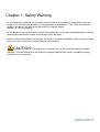
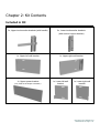
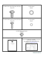
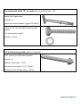
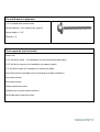
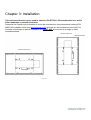
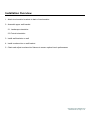
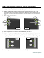
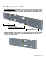
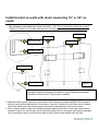
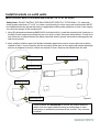
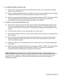
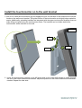
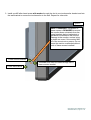
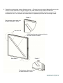
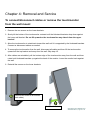
Installation Manual
Elo Touch Solutions
Wallmounting Kit for the 7001L
IDS Touchmonitors
SW602083 Rev E
Table of Contents
Chapter 1: Safety Warning ............................................................................................................................................... 3
Chapter 2: Kit Contents .................................................................................................................................................... 4
Included in Kit ................................................................................................................................................. 4
Chapter 3: Installation...................................................................................................................................................... 8
Installation Overview ...................................................................................................................................... 9
Attach touchmonitor brackets to back of touchmonitor................................................................................ 10
Assemble the upper wall bracket .................................................................................................................. 11
Install bracket on walls with studs measuring 16” or 24” on center ............................................................... 12
Install brackets on solid walls ........................................................................................................................ 14
Install the touchmonitor on to the wall bracket ............................................................................................ 16
Chapter 4: Removal and Service ..................................................................................................................................... 19
To connect/disconnect cables or remove the touchmonitor from the wall mount......................................... 19
Chapter 5: Technical Support ......................................................................................................................................... 20
Technical Assistance ..................................................................................................................................... 20
Agency Certifications .................................................................................................................................... 20
Getting in Touch with Us............................................................................................................................... 21
User Manual-7001 Wall Mount Kit
SW602083 Rev E, Page 2 of 21
Chapter 1: Safety Warning
Do not install this equipment on any wall or structure that is not capable of supporting 4 times the
weight of the touchmonitor, brackets, and any accessories attached to it. The 7001L touchmonitor
weighs in excess of 149 lbs with the optional Elo computer module.
149 lbs x 4 = 596 lbs (246kg).
Do not leave out any required parts or leave the touchmonitor on the wall unattended without securely
fastening all brackets and screws as instructed in this document.
Failure to follow all installation instructions can result in an unsafe installation. Serious injury or death
can occur if the touchmonitor unexpectedly falls on someone.
CAUTION: This wall mount is intended for use only with the maximum weights
indicated. Use with heavier than the maximum weights indicated may result in instability causing
possible injury or equivalent.
User Manual-7001 Wall Mount Kit
SW602083 Rev E, Page 3 of 21
Chapter 2: Kit Contents
Included in Kit
2x, Upper touchmonitor brackets (with handle)
2x, Lower touchmonitor brackets
(with service support bracket)
1x, Upper-left wall bracket
1x, Upper spacer bracket
(only used for landscape orientation)
1x, Upper-right wall bracket
1x, Lower-left wall
bracket
1x, Lower-right wall
bracket
User Manual-7001 Wall Mount Kit
SW602083 Rev E, Page 4 of 21
2x, M8x14 Allen Head Cap Screws with Nylock
2x, M8 washers
Class 10.9
Grade 2
10x, M5x12 Allen Head Cap Screws with Nylock
10x, M5 washers
Class 12.9
Grade 2
4x, M5x5 Philips head screws
Class 8.8
1 Printed installation guide
Dimensional drawing for mounting in landscape
and portrait orientation.
Also available within drawing MS601422
available at www.elotouch.com
User Manual-7001 Wall Mount Kit
SW602083 Rev E, Page 5 of 21
For metal stud walls 16” on center (Max drywall thickness = 5/8”)
Heavy Duty Toggle anchor
Quantity = 8
Additional anchors available (Toggler P/N 25014)
1/4-20 x 2-1/2” hex head steel machine screws,
grade 5
1/4” steel washers, grade 2
Quantity = 8 each
For solid masonry walls (brick or concrete)
5/16” (or 8mm) concrete sleeve anchors
Quantity = 8
Fastener thread type = 1/4-20
Minimum anchor length = 2-1/2” (70mm)
Minimum pullout strength rating = 1500 lbs.
User Manual-7001 Wall Mount Kit
SW602083 Rev E, Page 6 of 21
For solid wood or plywood
1/4” hex head steel wood screws,
Screw material = zinc coated steel, grade 5
Screw length =1-1/2”
Quantity = 8
Tools required (not included)
Power drill
3/16” drill bit for wood
(for installation on wood structured walls walls)
5/16” drill bit for masonry (for installation on masonry walls)
1/2” drill bit for metal (for installation on metal stud walls)
3mm allen wrench (required only for mounting in portrait orientation)
6mm allen wrench
4mm allen wrench
Philips head screw driver
Hammer (for concrete sleeve anchors)
Stud finder and construction level
User Manual-7001 Wall Mount Kit
SW602083 Rev E, Page 7 of 21
Chapter 3: Installation
This wall mount bracket can be used to attach an Elo ET7001L IDS touchmonitor to a wall in
either landscape or portrait orientation.
Determine the location and orientation to mount the touchmonitor using dimensional drawing P/N
MS601422 available online from www.elotouch.com. With this kit, the touchmonitor can ONLY be
mounted in landscape or portrait orientation and MUST NOT be mounted at an angle or tilted
forward/backward.
User Manual-7001 Wall Mount Kit
SW602083 Rev E, Page 8 of 21
Installation Overview
1. Attach touchmonitor brackets to back of touchmonitor
2. Assemble upper wall bracket
2.1. Landscape orientation
2.2. Portrait orientation
3. Install wall brackets on wall
4. Install touchmonitor on wall bracket
5. Check and adjust touchmonitor flatness to ensure optimal touch performance
User Manual-7001 Wall Mount Kit
SW602083 Rev E, Page 9 of 21
Attach touchmonitor brackets to back of touchmonitor
1. Loosely install one M8 allen head screw and washer through one of the upper touchmonitor
brackets and into the back of the touchmonitor. See Figure 1.
2. Install two M5 allen head screws with washers through the bracket and into the back of the
touchmonitor. Make sure the bracket is straight before tightening the screws because there are
extra holes in the back of the touchmonitor that can make the bracket not line up properly. See
Figure 1.
3. Tighten the M8 screw from step 1.
M8
M8
M5
M5
M5
M5
Figure 1
Figure 2
4. Repeat this procedure for the other top side handle bracket. See Figure 2.
5. Place one of the lower touchmonitor brackets over the two M5 screw holes on the bottom of the
touchmonitor and install one M5 allen head screw with washer through the bracket into the
touchmonitor. Approximately center the screw in the slot on the bracket and tighten the screws
only slightly so the bracket can be adjusted later during touchmonitor installation. See Figure 3.
Figure 3
Figure 4
M5
M5
M5
M5
6. Repeat this procedure for the other bottom side bracket. See Figure 4.
User Manual-7001 Wall Mount Kit
SW602083 Rev E, Page 10 of 21
Assemble the upper wall bracket
1. For landscape orientation, fasten the upper-left wall bracket to the upper spacer bracket using two
of the philips head M5 screws included in the kit. Fasten the upper-right wall bracket to the other
side of the upper spacer bracket using the other two philips head M5 screws included with the kit.
M5
M5
Figure 5
M5
Upper–left wall bracket
M5
Upper spacer bracket
(Required for landscape orientation)
Upper-right wall bracket
2. For portrait orientation, fasten the upper-left and upper-right wall brackets to each other using two
M5 philips head screws included with the kit. The upper spacer bracket is not used for portrait
orientation and can be discarded.
Figure 6
M5
M5
User Manual-7001 Wall Mount Kit
SW602083 Rev E, Page 11 of 21
Install bracket on walls with studs measuring 16” or 24” on
center
1. Use a stud finder to locate studs. The bracket must be mounted to at least two studs using
two screws in each stud. Max drywall thickness = 5/8”. Do not attempt to secure the bracket
directly to drywall or to anything else that cannot safely support four times the weight of the
touch-monitor.
Wall stud
Wall stud
Mounting hole
Wall panel
Mounting hole
Mounting hole
Mounting hole
Figure 7
These brackets are REQUIRED to ensure the monitor does not detach from
the upper brackets during an earthquake or other inadvertent/accidental
movement of the monitor. They must be installed!
2. Mark the mounting hole locations on the wall per Elo dimensional drawing #MS601422 (included
with kit) ensuring the locations are in the center of the stud. Check to be sure there are no objects
behind the holes (electrical wires or pipes) that could be damaged by wall-mount screws.
3. Have a helper hold the upper wall bracket assembly against the wall to ensure the hole locations
marked in step 2 line up correctly with the mounting screw slots in the upper wall bracket assembly.
Use a carpenter’s level to confirm the bracket is level. Remove the bracket from the wall.
User Manual-7001 Wall Mount Kit
SW602083 Rev E, Page 12 of 21
4. Drill one 1/8” (4mm) pilot hole through the drywall and into the studs at each marked location (8
locations total). Then enlarge the pilot hole and install screws and anchors per the
recommendations below:
For wood studs only:
4.1. Enlarge the pilot holes to 3/16”. Ensure the pilot holes are at least 2-1/2” deep.
4.2. Place upper wallmount bracket assembly against wall and install one 1/4” wood screw and
washer into each hole (4 total). Check and adjust for level before tightening screws.
4.3. Attach the lower left and right brackets using the same procedure. NOTE: The lower brackets
are required safety feature of this wall-mount system. Do not leave the touchmonitor
unattended without them being installed. See figure 7 for illustration.
For steel studs only:
4.1. Enlarge the hole to 1/2". (Do not enlarge the drywall or stud hole to any more than 1/2”)
4.2. Install the heavy duty toggle anchor by holding the metal channel flat alongside the plastic
straps and slide the channel through the drilled hole.
4.3. Hold ends of strap between thumb and forefinger and pull toward you until channel rests flush
behind wall. Slide plastic cap along straps with other hand until flange of cap is flush with wall.
4.4. Place thumb between straps at wall. Push thumb side to side, snapping off straps level with
flange of cap.
4.5. Place upper wallmount bracket assembly against wall and install one 1/4-20 hex head
machine screw and washer into each anchor (4 total). Check and adjust for level before
tightening screws.
4.6. Attach the lower left and right brackets using the same procedure. NOTE: The lower brackets
are a required safety feature of this wall-mount system. Do not leave the touchmonitor
unattended without installing them. See figure 7 for illustration.
Safety warning: Mounting screws in the center spacer bracket are unnecessary and will not
support the weight of the touchmonitor by itself. Holes may be drilled in the center spacer bracket
up to maximum 2” diameter for cables to pass through but do not remove the bracket from the
assembly. It is a required part of the wall-mount system when mounting a touchmonitor in
landscape orientation.
User Manual-7001 Wall Mount Kit
SW602083 Rev E, Page 13 of 21
Install brackets on solid walls
(Brick, concrete, wood, or stud walls with studs NOT 16” or 24” on center)
Safety Note: DO NOT INSTALL THE WALL BRACKET DIRECTLY TO DRYWALL. For walls with
studs spaced other than 16” or 24” on center, wood blocking or other structural reinforcement MUST
be installed behind the drywall according to applicable building code guidelines so that it can support
four times the weight of the touchmonitor.
1. Using Elo dimensional drawing #MS601422 (included with kit), mark the mounting hole locations on
the wall (8 total) ensuring the locations are over studs or other structural reinforcement. Check to be
sure there are no objects behind the holes (electrical wires or pipes) that could be damaged by the
wall-mount screws.
2. Have a helper hold the upper wall bracket assembly against the wall to ensure the hole locations
marked in step 1 line up correctly with the mounting screw slots on the upper wall bracket assembly
and use a carpenter’s level to confirm the bracket is level. Remove the bracket from the wall.
Mounting hole
Solid Wall Structure
Mounting hole
Mounting hole
Mounting hole
Figure 8
These brackets are REQUIRED to ensure the monitor does not
detach from the upper brackets during an earthquake or other
inadvertent or accidental movement of the monitor. They must be
installed!
User Manual-7001 Wall Mount Kit
SW602083 Rev E, Page 14 of 21
3. For solid wood wall structures only:
3.1. Drill one 3/16” (5mm) pilot hole into the wall structure in each of the marked hole locations.
Holes must be at least 2-1/2”.
3.2. Attach the upper bracket assembly to the wall with one 1/4” hex head wood screw and washer
through each slotted hole on the upper bracket assembly (4 screws total).
3.3. Attach the lower left and right brackets using the same procedure. NOTE: The lower brackets
are required safety feature of this wall-mount system. Do not leave the touchmonitor
unattended without them being installed. See figure 8 for illustration.
4. For brick or concrete wall structures only:
4.1. Drill one 5/16” (6mm) hole into the wall structure using a solid carbide tipped masonry bit in
each of the marked hole locations. The holes must be at least 2-1/2” (64mm) deep. Do not
ream the hole or allow the bit to wobble. Through drilling is allowed when using hollow block
or brick.
4.2. Clean each hole with dry oil-free compressed air or a nylon brush.
4.3. Assemble the washers and nuts on the concrete sleeve anchors so the anchor extends above
the nut slightly.
4.4. Place the upper bracket assembly against the wall and insert one concrete sleeve anchor
through the bracket and into each hole in the wall (4 total). Use a hammer to ensure the
anchor is seated completely.
4.5. Check the bracket for level and tighten the nut on each anchor 3 to 5 turns past hand tight or
10-15 ft-lbs.
4.6. Attach the lower left and right brackets using the same procedure. NOTE: The lower brackets
are a required safety feature of this wall-mount system. Do not leave the touchmonitor
unattended without installing them. See figure 8 for illustration.
Safety warning: Mounting screws in the center spacer bracket are unnecessary and will not
support the weight of the touchmonitor by itself. Holes may be drilled in the center spacer bracket
up to maximum 2” diameter for cables to pass through but do not remove the bracket from the
assembly. It is a required part of the wall-mount system when mounting a touchmonitor in
landscape orientation.
User Manual-7001 Wall Mount Kit
SW602083 Rev E, Page 15 of 21
Install the touchmonitor on to the wall bracket
1. Use a lift to raise the touchmonitor up and engage the pins on the back of the touchmonitor with the
hooks on the wall mount bracket. Tilting the bottom of the touchmonitor out slightly helps make this
easier. Additionally, extending handles are integrated with the upper touchmonitor brackets that can
make lifting and positioning the touchmonitor easier. The handles can be hidden behind the
touchmonitor while mounted on the wall.
Figure 8
Pin
Handle
Hook
2. Lower the touchmonitor carefully so the M5 screw hole on the lower wall bracket is visible through
the slot in the lower touchmonitor bracket. Adjust the position of the lower touchmonitor brackets if
needed. Repeat for other side.
User Manual-7001 Wall Mount Kit
SW602083 Rev E, Page 16 of 21
3. Install one M5 allen head screw with washer through the slot in one touchmonitor bracket and into
the wall bracket to secure the touchmonitor to the wall. Repeat for other side.
Figure 9
SAFETY WARNING: Installation of
these screws is REQUIRED to ensure
the monitor does not detach from the
upper brackets during inadvertent or
accidental movement of the monitor.
Damage to the monitor, serious injury,
or death can occur if the monitor falls
off of the mount onto a person. Do not
leave the monitor unattended without
both of these screws installed!
Lower monitor bracket
Threaded hole must be visible through slot in
lower monitor bracket
Lower wall bracket
User Manual-7001 Wall Mount Kit
SW602083 Rev E, Page 17 of 21
4. Check the touchmonitor screen flatness using a ~1.5 meter long ruler placed diagonally across the
screen in both directions. If the gap between the ruler and the screen does not meet the
requirements below, loosen the lower M5 mounting screws and adjust the lower corners of the
touchmonitor in or out to flatten the screen before re-tightening the lower M5 mounting screws.
Detail B
Gap between glass and ruler
at each end must = 0 mm
See detail B
0-3MM gap between glass and ruler is
OK near center of screen
Detail C
See detail C
Gap between glass and ruler
at each end must = 0mm
User Manual-7001 Wall Mount Kit
SW602083 Rev E, Page 18 of 21
Chapter 4: Removal and Service
To connect/disconnect cables or remove the touchmonitor
from the wall mount
1. Remove the two screws on the lower brackets.
2. Slowly tilt the bottom of the touchmonitor outward until the kickstand brackets drop down against
the lower wall bracket. Do not lift upward or the touchmonitor may detach from the upper
bracket!
3. Allow the touchmonitor to rotate back toward the wall until it is supported by the kickstand brackets.
Connect or disconnect cables as needed.
4. To remove the touchmonitor from the wall, disconnect all cables and then lift the touchmonitor
upward off the top bracket and away from the wall. Skip step 4-5.
5. After cables are reinstalled, pull the bottom edge of the touchmonitor away from the wall and then
rotate both kickstand brackets up against the back of the monitor. Lower the monitor back against
the wall.
6. Reinstall the screws on the lower brackets.
Remove this screw to tilt monitor
(both sides)
Kickstand bracket
User Manual-7001 Wall Mount Kit
SW602083 Rev E, Page 19 of 21
Chapter 5: Technical Support
Technical Assistance
Visit www.elotouch.com/products for technical specifications for this device
Visit www.elotouch.com/go/websupport for online self-help.
Visit www.elotouch.com/go/contactsupport for technical support.
For all technical question and inquiries, please contact Elo Touch Solutions. Worldwide technical
support phone numbers are available on the last page of this use manual.
Agency Certifications
Check the latest version of this document on the Elo website for all agency approval status
User Manual-7001 Wall Mount Kit
SW602083 Rev E, Page 20 of 21
Check out our website
www.elotouch.com
Get the latest...
• Product Information
• Specifications
• Upcoming events
• Press releases
• Software drivers
Getting in Touch with Us
To find out more about the extensive range of Elo touch solutions, visit our website at
www.elotouch.com, or simply call the office nearest you:
North America
Elo Touch Solutions
1033 McCarthy Blvd
Milpitas, CA 95035
Tel 800-ELO-TOUCH
Tel + 1 408 597 8000
Fax +1 408 597 8050
[email protected]
Europe
Tel +32 (0) 16 70 45 00
Fax +32 (0)16 70 45 49
[email protected]
Asia-Pacific
Tel +86 (21) 3329 1385
Fax +86 (21) 3329 1400
www.elotouch.com.cn
Latin America
Tel 786-923-0251
Fax 305-931-0124
www.elotouch.com.ar
Disclaimer
The information in this document is subject to change without notice. Elo Touch Solutions, Inc. and its affiliates makes no
representations or warranties with respect to the contents herein, and specifically disclaims any implied warranties of
merchantability or fitness for a particular purpose. Elo reserves the right to revise this publication and to make changes
from time to time in the content hereof without obligation of Elo to notify any person of such revisions or changes.
No part of this publication may be reproduced, transmitted, transcribed, stored in a retrieval system, or translated into any
language or computer language, in any form or by any means, including, but not limited to, electronic, magnetic, optical,
chemical, manual, or otherwise without prior written permission of Elo Touch Solutions, Inc.
Elo, the Elo logo, Elo Touch, Elo Touch Solutions and Elo TouchSystems are trademarks of Elo Touch Solutions, Inc. and its
affiliates in the United States, other countries, or both.
Copyright © 2014 Elo Touch Solutions, Inc. All rights reserved.
User Manual-7001 Wall Mount Kit
SW602083 Rev E, Page 21 of 21