1
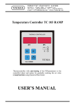
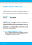
PHOTOVOLTAIC MODULES:
USER MANUAL
01
Photovoltaic Modules Eurener
www.eurener.com
INDEX
SAFETY INSTRUCTIONS ...................................................................... 03
CERTIFICATES AND WARRANTY ........................................................ 04
MANUFACTURING DETAILS ................................................................ 06
IMPORTANT FIELD DESIGN CONSIDERATIONS ................................ 10
MOUNTING INSTRUCTIONS ................................................................. 12
INSTRUCTIONS OF USE ....................................................................... 15
GROUNDING .......................................................................................... 19
MAINTENANCE CONDITIONS............................................................... 20
TECHNICAL SPECIFICATIONS ............................................................. 21
02
Photovoltaic Modules Eurener
www.eurener.com
SAFETY INSTRUCTIONS
We strongly recommend to fully read and understand the following
instructions as well as the modules back sticker before handling or
connecting your photovoltaic module.
Eurener modules are qualified for application class A: Hazardous voltage (IEC
61730: higher than 50V DC; EN 61730: higher than 120V), hazardous power
applications (higher than 240W) where general contact access is anticipated
(modules qualified for safety through EN IEC 61730-1 and -2 within this
application class are considered to meet the requirements for safety class II).
Warning: Any defect in Eurener photovoltaic modules produced by non
compliance of the following instructions may void the warranty. Eurener S.L.
shall not be responsible for unintended use or mishandling of its
manufactured products.
03
Photovoltaic Modules Eurener
www.eurener.com
CERTIFICATES AND WARRANTY
ISO 9001:2008 Quality Management System
Certified by Bureau Veritas
ISO 14001:2001 Environmental Management
System Certified by Bureau Veritas
Following all valid quality and environmental norms, Eurener counts with
recognition of the most prestigious certification organisms such as TÜV Rheinland,
contracted since 2007 to perform IEC Standards inspections.
04
Photovoltaic Modules Eurener
www.eurener.com
CERTIFICATES AND WARRANTY
Eurener photovoltaic modules warranty ensures the following aspects: The
product warranty provided by Eurener for photovoltaic modules implies compliance
with the following points:
1. Total absence of manufacturing defects over a 12 years period, starting on
sale date to the first buyer (excluding connectors and interconnection cables which
are not intrinsic part of the module).
2. Rated power supply over a minimum period of 25 years. We proudly guarantee
a power loss that does not exceed 1,75% after the first year, and then a linear regression
of 0,75% per year during the first 25 years.
05
Photovoltaic Modules Eurener
www.eurener.com
MANUFACTURING DETAILS
Photovoltaic modules are made of the following materials.
Frame: Made of anodized aluminium, provides a perfect clamping system
to the supporting structure.
Glass: low iron, 4mm thick tempered glass that provides stiffness to the
laminate and protection for the active side of the solar cells.
EVA: (Ethyl Vinyl Acetate): Cells circuit encapsulating material.
Solar Cells: Made of High efficiency crystalline silicon. They are the
components that generate electricity within the module.
Back sheet foil: Specially designed multi-layer foil, it provides electrical
insulation to the rear side of the module.
Junction box: IP 65 specified, provides a safe electrical connection
between the module and the overall installation.
06
Photovoltaic Modules Eurener
www.eurener.com
MANUFACTURING DETAILS
:: Schematic of a photovoltaic laminate ::
Glass
EVA layer
Solar Cells electric circuit
EVA layer
Backsheet foil
07
Photovoltaic Modules Eurener
www.eurener.com
MANUFACTURING DETAILS
:: Junction box :: By-pass diodes ::
Photovoltaic modules are protected by by-pass diodes, a semiconductor device that
provides very fast commutations between forward and reverse conducting state
(less than 1ns in small devices of 5 mm diameter).
These diodes protect the module against cells partial shading, avoiding the module
to completely stop functioning.
CAUTION: For security reasons, it is important not to extract diodes from
the junction box.
In case of by-pass diodes malfunction, these should be replaced by original
diodes. Modules affected should remain disconnected during the time
needed for replacement, to ensure that the photovoltaic field remains in
open circuit.
08
Photovoltaic Modules Eurener
www.eurener.com
MANUFACTURING DETAILS
:: Schematic of the By-pass diode protection in a module ::
09
Photovoltaic Modules Eurener
www.eurener.com
IMPORTANT FIELD DESIGN CONSIDERATIONS
Under normal conditions, a photovoltaic module can produce more current and/or
voltage than reported at standard test conditions.
Accordingly, the values of Isc and Voc labeled on a module should be multiplied by
a factor of 1,25 when determining component voltage ratings, conductor current
ratings, fuse sizes, and size of controls connected to the PV output.
1. Intensity / Current consideration:
• Eurener photovoltaic modules are designed to sustain reverse current ratings up to
12A. Observe this maximal reverse current bearing capacity when connecting
modules in parallel. If the possible reverse current through a module might become
higher than this value, appropriate diodes must be used in each module or string of
modules connected in parallel.
• Only connect modules with the same rated output current in series.
• Under no circumstances any Eurener module shall be exposed to concentrated
sunlight.
10
Photovoltaic Modules Eurener
www.eurener.com
IMPORTANT FIELD DESIGN CONSIDERATIONS
2. Tension / Voltage consideration:
• Only connect modules or series combinations of modules with the same voltage in
parallel.
• With a serial interconnection of modules, the sum of the open circuit voltage at
Standard Test Conditions (Voc @ STC) must not overtake the maximum system
voltage indicated.
Warning: Due to the voltage increase induced by very low temperature ranges, the
maximum number of modules will have to be corrected according to the place and
correction parameters stated in the formula below. The lowest temperature of the
region where the photovoltaic modules will be installed must be taken into account.
Maximum tension of the system
maximum number of modules =
Voc25ºc + ((Tª - 25 ) x nº cell x (-0.00215))
11
Photovoltaic Modules Eurener
www.eurener.com
MOUNTING INSTRUCTIONS
The positioning of the module should be done in accordance with the indications
established by the technician responsible for the technical project or official project.
The inclination and orientation angles should be respected. Projected shades
towards the active area should be avoided, as they generate decrease in the
electrical production.
Safety distances between lines of modules must be respected to avoid
overheating. Note that an excess rise of temperature causes efficiency losses in the
module.
Grid connected installations as well as stand alone installations must be done in
accordance with the recommendations and requirements established as per the
local Electro technical Regulation for Low Tension.
The use of structural elements such as flanged type locks or cable crimping
clamps to fix the cables must be avoided. In any case, excessive tension of the
connecting cables must be avoided.
12
Photovoltaic Modules Eurener
www.eurener.com
MOUNTING INSTRUCTIONS
Actions to take into account when fixing modules onto a supporting structure:
Mechanical installation on a supporting structure must be done in accordance with
the safety conditions established by the local regulation for low tension and
legislation on labour risk prevention.
The cable crimping press from the junction box should be oriented downward in
the same direction as the inclination.
The mounting structure and hardware must be made of durable, corrosion- and
UV-resistant material.
The mounting system must be capable of securely fixing modules exposed to
uplift or load pressures of more than 2’400 N/m².
Either clamps or bolts are suitable for mechanical fixation on the supporting
structure, although clamps are highly recommended as they do not require drilling of
the aluminum frame. The torque on the clamp bolt shall be around 8-10Nm.
A minimum of 4 fixation points shall be used, see the drawings facilitated on next
page for location details.
13
Photovoltaic Modules Eurener
www.eurener.com
MOUNTING INSTRUCTIONS
14
Photovoltaic Modules Eurener
www.eurener.com
INSTRUCTIONS OF USE
Eurener modules are supplied with IEC certified cables and connectors for serial
electrical connections, which technical specifications are as follows:
- 4mm2, 1m long copper conductor,
- Inner and sheath insulation made of polyolefin reticulated compound
- Maximum conductor temperature: 120ºC / Maximum ambient Tº: 60ºC
For additional extension cables use only suitable cables
Since Eurener photovoltaic modules generate DC power, electrical polarities must
be respected. These polarities come indicated with the + sign for the positive part,
and the - sign for the negative part, both marked on the connectors.
Negative
Positive
15
Photovoltaic Modules Eurener
www.eurener.com
INSTRUCTIONS OF USE
Manipulation, installation and maintenance of photovoltaic modules must be
carried out by qualified technicians. In any case, the technicians manipulating the
installation must comply with the safety norms in force and use protective clothes
with isolation superior to 1000 V.
Avoid modules installation in rainy or humidity conditions.
Do not install the module in case of breakage of the glass cover or any other
structural element.
Avoid leaning on the module or overcharging it.
If Eurener modules are installed in or on roofs, an appropriately rated fireproof
underlay is needed.
Do not use mirrors or other hardware to artificially concentrate sunlight on the
module.
16
Photovoltaic Modules Eurener
www.eurener.com
INSTRUCTIONS OF USE
Protective elements between modules series and inverter must be used as per
the local norms and safety regulations. Typical protective elements such as fuses or
magneto caloric devices shall display breaking capacity superior to the intensities of
the series of modules.
The non installation of this type of devices could cause that, in case of error in
polarity connections, the inverted series act as energy receptors and damage live
parts of the module.
Avoid the installation of photovoltaic modules next to sources of toxic, corrosive
or inflammable vapours.
Do not manipulate any component of the module.
Do not remove the label with technical specifications.
Avoid tearing the back sheet foil with assembly tools.
17
Photovoltaic Modules Eurener
www.eurener.com
INSTRUCTIONS OF USE
Do not deposit broken modules in garbage containers or landfills because it could
be dangerous. In case of breakage, electrical malfunction and in general any event
that could cause the end of the module useful life, please contact your module
supplier for adequate elimination and/or recycling in accordance with European
norms.
Warning: Any failure in the module produced by the non-compliance
with the instructions of use contained in this manual may void our
product warranty.
No responsibility will be assumed by Eurener S.L. in the event of an
inadequate module manipulation.
18
Photovoltaic Modules Eurener
www.eurener.com
GROUNDING
Functional grounding is not foreseen for Eurener photovoltaic modules. If it is
performed, local electric codes and regulations have to be observed, and used
grounding means have to be isolated from live parts by reinforced insulation.
In any case the grounding screws, bolts or other parts have to be used separately
from the module mounting parts. The grounding holes should be situated as per the
drawing facilitated below.
For frame grounding: a bolded or screwed connection is required, it incorporates:
- a serrated stainless steal star washer under the screw head so as to penetrate the
nonconductive coating of the anodized frame
- 2 or more screws or 2 full threads of a single screw shall engage the metal
Grounding Cable
Frame profile
19
Photovoltaic Modules Eurener
www.eurener.com
Serrated star washer
MAINTENANCE CONDITIONS
It is recommended to periodically clean the module with water or non abrasive
detergent, avoiding the use of high pressure cleaning equipments. Perform an
annual control of the electrical connexions state, cables, fixing elements and
supporting structures.
Check technical features of the modules to verify its efficiency.
Visually inspect the photovoltaic modules in order to detect hot spots,
delaminations, colour changes of the cells, broken glass, etc.
Warning: No responsibility will be assumed by Eurener,
S.L. for a possible loss of efficiency nor will it be
considered that there is a defect in production of the
module supplied if it is due to the non-compliance with
these instructions of use and maintenance.
20
Photovoltaic Modules Eurener
www.eurener.com
TECHNICAL SPECIFICATIONS
MEPV 220-250 Modules
21
Photovoltaic Modules Eurener
www.eurener.com
TECHNICAL SPECIFICATIONS
22
Photovoltaic Modules Eurener
www.eurener.com
TECHNICAL SPECIFICATIONS
Data measured in standard test conditions: Radiation of 1000 W/m2,
spectrum AM 1.5 and cell temperature of 25 ºC
These are typical ratings, always refer to a module back sticker for
detailed electrical ratings
23
Photovoltaic Modules Eurener
www.eurener.com
TECHNICAL SPECIFICATIONS
PEPV 220-250 Modules
24
Photovoltaic Modules Eurener
www.eurener.com
TECHNICAL SPECIFICATIONS
25
Photovoltaic Modules Eurener
www.eurener.com
TECHNICAL SPECIFICATIONS
Data measured in standard test conditions: Radiation of 1000 W/m2,
spectrum AM 1.5 and cell temperature of 25 ºC
These are typical ratings, always refer to a module back sticker for
detailed electrical ratings
26
Photovoltaic Modules Eurener
www.eurener.com
CONTACT DETAILS
Eurener, S.L.
C/ Gabriel Miró, 2
03380 Bigastro (Alicante)
SPAIN
Tel. +34 96 677 24 89
Fax +34 96 677 20 50
[email protected]
www.eurener.com
27
Photovoltaic Modules Eurener
www.eurener.com