1
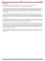
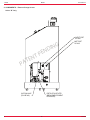
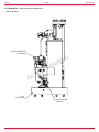
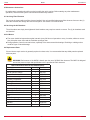
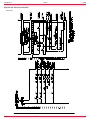
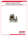
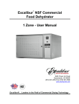
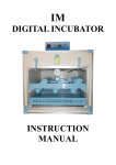
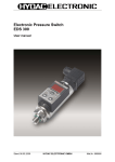
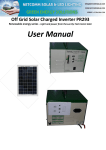
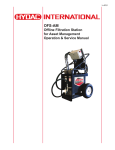
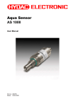
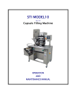
L-2999
MAFH
Operating Maintenance and
Troubleshooting Manual
L-2999 | Created 9.2012
User Manual
MAFH
L-2999
- TABLE OF CONTENTS1. Introduction ………………………………………………………………………………………………………………………...4
2. Warnings, Cautions and Notes …………………………………………………………………………………………………5
3. Specifications ……………………………………………………………………………………………………………………...7
4. Components ………………………………………………………………………………………………………………………..8
5. Operating Instructions …………………………………………………………………………………………………………...11
5.1 Percent Saturation Water in Oil Display ……………………………………………………………………………………..11
5.2 Fluid Oscillation in Auto Mode ………………………………………………………………………………………………..11
5.3 Drain Mode ……………………………………………………………………………………………………………………..11
6. Maintenance Instructions ………………………………………………………………………………………………………..12
6.1 Servicing Filter Elements ……………………………………………………………………………………………………...12
6.2 Servicing Air Breathers ………………………………………………………………………………………………………..12
6.3 AC Motors ………………………………………………………………………………………………………………………12
6.4 Replacement Parts …………………………………………………………………………………………………………….12
7. Warranty …………………………………………………………………………………………………………………………….13
Appendix 1A - Hydraulic Schematic …………………………………………………………………………………………..14
Appendix 2A - Electrical Schematic …………………………………………………………………………………………...15
Appendix 3A - Troubleshooting ………………………………………………………………………………………………..17
Appendix 4A - Frequently Asked Questions …………………………………………………………………………………18
HYDAC
En
TOC
L-2999MAFH User Manual
1. INTRODUCTION
HYDAC’s patent pending dewatering unit (MAFH) is the first of its kind on the market. The MAFH offers
fully automated dewatering of hydraulic fluids and a variety of other petroleum based fluids.
The operating principle of the MAFH differs from existing dewatering methods. The MAFH is a positive pressure system that
uses 100% mass transfer to remove water from the operating fluid. Room air is heated using a proprietary method to improve the ability of the air to absorb water vapor. This heated air is then distributed upwards in the reaction chamber through cascading droplets of operating fluid. The heated air stream removes free, emulsified, & dissolved water and some dissolved gases.
In most traditional industrial vacuum dehydrators, mass transfer is also the means to dewater. A mild/medium vacuum expands the room air and proportionately reduces the relative humidity of the air. The air flow is limited to the displacement of the vacuum pump. Higher efficiency vacuum units use a closed cycle to seal operating fluid with high heat and high vacuum to boil off water. These units have high efficiency but have low flow rates and can potentially damage the operating fluid over time.
Since the air flow rate of the HYDAC MAFH is not limited by vacuum pump displacement, it is more effective in dewatering operating fluids under similar conditions and flow rates than the above technologies. In addition, the MAFH does not have the initial and maintenance economic disadvantages of a vacuum pump based system.
The MAFH uses a regenerative air injection system to heat and distribute room air into the reaction chamber. The optional compressed air system uses an available dried, clean air source. Any residual fluid mist is mechanically separated from the moist air stream before it is vented from the chamber. The system fluid is cycled through the reaction chamber via a system including a vane pump, two valves, and three filters. During the first cycle, fluid is pumped and gently sprayed on top of the loose, reticulated media until the fluid level in the sump triggers the high float switch. The fluid is then pumped from the pump and returned to the customer.
The MAFH is controlled by a control system which monitors system function and controls the cycle operation. An on-board water sensor (AS1000) monitors the relative humidity of the operating fluid and displays the actual humidity value at the control panel.
4En
HYDAC
User Manual
MAFH
L-2999
WARNING!
BEFORE RUNNING THIS MAFH-A,
THE OPERATOR MUST READ AND UNDERSTAND
THE CONTENTS OF THIS MANUAL!
THE MAFH-A MUST REMAIN IN AN UPRIGHT POSITION AT ALL
TIMES. IF THE UNIT IS TIPPED MORE THAN 15 DEGREES OR
IS KNOCKED OVER CONTACT HYDAC IMMEDIATELY. DO NOT
ATTEMPT TO OPERATE THE UNIT IF IT HAS BEEN TIPPED OVER
OR DROPPED.
HIGHLY AERATED OIL WITH EXCESSIVE FOAM MAY CAUSE
THE FLOAT SWITCHES INTERNAL TO THE FLUID CHAMBER
TO MALFUNCTION. IF THE OIL IS AERATED ALLOW THE FLUID
TO SETTLE AND THE AIR TO DISSIPATE PRIOR TO RUNNING IT
THROUGH THE MAFH-A.
HYDACEn
5
L-2999MAFH User Manual
2. WARNINGS, CAUTIONS AND NOTES
Recognize Safety Information
This is the safety alert symbol. When you see this symbol on your machine or in this manual, be alert
for the potential of personal injury. Follow the precautions and safe operating practices highlighted by this symbol.
A signal word — DANGER, WARNING, or CAUTION — used with the safety alert symbol. DANGER identifies the most serious hazards. General precautions are on CAUTION labels.
Follow Safety Instructions
Read the safety messages in this manual and on the machine. Follow these warnings and instructions carefully. Review them frequently. Be sure all operators of this machine understand every safety message. Replace safety labels immediately if missing or damaged.
Operate Only If Qualified
Do not operate this machine unless you have read the operator’s manual carefully and you have been qualified by supervised training and instruction. Familiarize yourself with the job site and your surroundings before operating.
Inspect Machine
Inspect the equipment carefully before each use. Keep all parts in good condition and properly installed. Fix damage and replace worn or broken parts immediately. Pay special attention to hydraulic hoses and electrical power cord.
Handle Fluids Safely—Avoid Fires
Filtering of fuel or other flammable liquids is not recommended. Store flammable fluids away from fire hazards. Do not incinerate or puncture pressurized containers. Make sure machine is clean of trash, grease, and debris. Do not store oily rags; they can ignite and burn spontaneously.
Prepare for Emergencies
Be prepared if a fire starts. Keep a first aid kit and fire extinguisher handy. Keep emergency numbers for doctors, ambulance service, hospital, and fire department near your telephone.
Practice Safe Maintenance
Understand service procedure before doing work. Work area should level, clean, and dry. Before servicing machine:
- Position machine on a level surface
- Allow to cool if hot
Keep all parts in good condition and properly installed. Fix damage immediately. Replace worn or broken parts. Remove any buildup of grease, oil, or debris.
Handle Chemical Products Safely
Direct exposure to hazardous chemicals can cause serious injury. Potentially hazardous chemicals used with equipment include such items as lubricants, coolants, paints, and adhesives. A Material Safety Data Sheet (MSDS) provides specific details on chemical products: physical and health hazards, safety procedures, and \
emergency response techniques. Check the MSDS before you start any job using a hazardous chemical. That way you will know exactly what the risks are and how to do the job safely. Then follow procedures and recommended equipment. (Contact HYDAC prior to using with fluids other than hydraulic fluids).
Wear Protective Clothing
Wear close fitting clothing and safety equipment appropriate to the job. Operating equipment safety requires the full attention of the operator. Do not wear radio or music headphones while operating the machine.
Service Machines Safely
Tie long hair behind your head. Do not wear a necktie, scarf, loose clothing, or necklace when you work near machine tools or moving parts. If these items were to get caught, severe injury could result. Remove rings and other jewelry to prevent electrical shorts and entanglement in moving parts.
6En
HYDAC
User Manual
MAFH
L-2999
Illuminate Work Area Safely
Illuminate your work area adequately but safely. Use a portable safety light for working inside or under the machine. Make sure the bulb is enclosed by a wire cage. The hot filament of an accidentally broken bulb can ignite spilled fuel or oil.
Work In Clean Area
Before starting a job:
- Clean work area and machine
- Make sure you have all necessary tools to do your job.
- Have the right parts on hand.
- Read all instructions thoroughly; do not attempt shortcuts.
Use Proper Tools
Use tools appropriate to the work. Makeshift tools and procedures can create safety hazards. For loosening and tightening hardware, use the correct size tools. DO NOT use U.S. measurement tools on metric fasteners. Avoid bodily injury caused by slipping wrenches.
Dispose of Waste Properly
Improperly disposing of waste can threaten the environment and ecology. Use leak-proof containers when draining fluids. Do not use food or beverage containers that may mislead someone into drinking from them. Do not pour waste onto the ground, down a drain, or into any water source.
3. Specifications
Average delivered Flow Rate: 1.5 gpm (5.7 L/min)
Pump Flow Rate: 3 gpm (11.4 L/min)
Relief Pressure Setting: 100 psi (6.9 bar)
Weight (Approx.): 295 lbs (134 kg)
Operating Temperature (Hydraulic): 40° F to 160° F
*Depending on Viscosity (4° C to 71° C)
Operating Temperature (Electronic): 50° F to 113° F
*Depending on Viscosity (10° C to 45° C)
Environmental Rating: Type 2
Power Requirements: 120 VAC 60 HZ @ 15 A
Fluid Compatibility: Hydrocarbon Based Hydraulic Fluids
(Viton seals standard)
Viscosity: <1,000SUS
HYDACEn
7
L-2999MAFH User Manual
4. COMPONENTS – Element Change Access
Series “B” Only
OUTLET PORT
3/4" MJIC
T
N
TE
G
N
DI
INLET PORT
1/2" MJIC
N
E
P
PA
SUCTION VALVE
(P/N VDP-466)
PARTICLE FLUID FILTER
(REPLACEMENT ELEMENT
P/N 02561354)
8En
HYDAC
User Manual
MAFH
L-2999
4. COMPONENTS – Internal Component Reference
Series “B” Only
LIFTING LUG, 1"
INLET AIR FILTER
(P/N 02561357)
HOLE
DISCHARGE AIR FILTER
(P/N 02561357)
INLET AIR VACUUM GAUGE
(P/N VDP-361)
DISCHARGE AIR GAUGE
(P/N VDP-360)
CONTROL PANEL
(P/N VDP-476)
REACTION CHAMBER
AIR BLOWER ASSEMBLY
(P/N VDP-385)
HYDRAULIC PUMP/MOTOR
ASSEMBLY (P/N VDP-468)
T
N
TE
G
N
DI
N
E
P
PA
COOLING FAN COVER
VDP-388
Y-STRAINER
(P/N FB-188)
COOLING FAN
(P/N VDP-389)
HYDACEn
9
L-2999MAFH User Manual
4. COMPONENTS – Internal Component Reference
Series “B” Only
VALVE WITH MANIFOLD
(P/N VDP-610)
T
N
TE
G
N
I
D
N
E
P
PA
CART
(P/N VDP-392)
WATER SENSOR
(00909109)
10En
HYDAC
User Manual
MAFH
L-2999
5. Operating Instructions
The operator interface consists of five pilot devices: (1) Percent Saturation Water in Oil Display; (2) a blue “DRAIN CYCLE” Light. The Master Stop (3) push-pull red button; (4) a “DRAIN/OFF/AUTO” Selector switch, which illuminates when the unit is running in Auto Mode; and (5) a red “CHANGE FILTER” Light. The unit will start its normal cycle when the user turns the selector switch to “AUTO”.
5.1 Percent Saturation Water in Oil Display
The digital display (1) provides a readout of the saturation water level as the fluid enters the pump.
5.2 Fluid Oscillation in AUTO Mode
WARNING! During initial start-up of the MAFH unit, the suction line should be flooded with fluid to prime the MAFH pump. Do not run the pump without fluid in the suction line or pump damage will occur!
The system fluid is cycled through the reaction chamber in-between two level switches. During the first cycle, fluid is pumped and gently sprayed on top of the loose, reticulated media until the fluid level in the pump triggers the high float switch. The fluid is then pumped from the sump and returned to the customer reservoir.
The blue “DRAIN CYCLE” light (2) will illuminate when the high float switch is triggered and remain lit until the pump’s fluid level is below the lower switch. At any point during normal operation the element becomes clogged or enters into bypass the red “CHANGE FILTER” light (5) will illuminate, notifying the user the particulate filter element needs replaced.
5.3 Drain Mode
Drain mode is available for service and maintenance reasons. The user will have to move the selector switch to “DRAIN” and hold the switch in that position. The motors will run and blue “DRAIN CYCLE” light (2) will illuminate as long as the user holds the switch. Release switch immediately after air discharges from the unit.
HYDACEn
11
L-2999MAFH User Manual
6. Maintenance Instructions
No maintenance operations should be carried out while the unit is running. Before starting any other maintenance operations, ensure that the system is shut down and electrically isolated.
6.1 Servicing Filter Elements
Do not run the system without a filter element installed. Use only specified replacement filter elements. Access to the (3) fluid filter elements are through the lower access panel. See section 4 for exact location
6.2 Servicing the Air Breathers
The air breathers are simply hand tightened. Used breathers may require a wrench to remove. The (2) air breathers used are identical.
6.3 AC Motors
■ The motor should be inspected at regular intervals (every 500 hours of operation or every 3 months, whichever occurs first). Keep the motor clean and the ventilation openings clear.
■ During operation, listen for unusual noises, especially in the areas around the bearings. Rumbling or rubbing noises could be signs of internal damage.
6.4 Replacement Parts
Since minimum repair service is generally required on these units, it is recommended that any failed parts be replaced with new parts.
WARNING! Performance of the MAFH is based upon the use of HYDAC filter elements. The MAFH is designed around the pressure drops and specifications of the specified HYDAC elements.
MAFH DEHYDRATION STATION SPARE PARTS
Description
Quantity
Part Number
Inlet Air Filter
1
2561357
Inlet Air Vacuum Gauge
1
VDP-361
Control Panel
1
VDP-476
Air Blower Assembly
1
VDP-385
Hydraulic Pump/Motor
1
VDP-468
Cooling Fan Cover
1
VDP-388
Cooling Fan
1
VDP-389
Y-Strainer
1
FB-188
Discharge Air Gauge
1
VDP-360
Discharge Air Filter
1
2561357
Fluid Suction Valve with Solenoid
1
VDP-466
Cart
1
VDP-392
Water Sensor
1
00909109
Particulate Filter Element
1
02561354
Indicator
1
02561355
Valve with Manifold
1
VDP-610
12En
HYDAC
User Manual
MAFH
L-2999
7. WARRANTY
Warranty, Limitation of Liability and Remedies:
THERE IS NO WARRANTY OF MERCHANTABILITY OR FITNESS FOR ANY PARTICULAR PURPOSE WITH RESPECT TO ANY OF THE PRODUCTS, NOR IS THERE ANY OTHER WARRANTY EXPRESS OR IMPLIED, EXCEPT AS PROVIDED FOR HEREIN.
For a period of twelve months from the date of delivery from Seller or three thousand hours of use, whichever occurs first (the “Warranty Period”, Seller warrants that products manufactured by Seller when properly installed and maintained, and operated at ratings, specifications and design conditions, will be free from defects in material and workmanship. By way
of explanation and not limitation, the Seller does not warrant the service life of the filter elements as this is beyond the Seller’s control and depends upon the condition of the system into which the filter is installed.
Seller’s liability under any warranty is limited solely (in Seller’s discretion) to replacing (FOB original ship point), repairing or issuing credit for products that become defective during the Warranty Period. Purchaser shall notify Seller promptly
in writing of any claims and provide Seller with an opportunity to inspect and test the product claimed to be defective. Buyer shall provide Seller with a copy of the original invoice for the product, and prepay all freight charges to return any
products to Seller’s factory, or other facility designated by Seller. All claims must be accompanied by full particulars, including system operating conditions, if applicable.
Seller shall not be liable for any product altered outside of the Seller’s factory except by Seller or Seller’s authorized distributor, and then, as to the latter, only for products which have been assembled by the distributor in accordance with Seller’s written instructions. Nor shall Seller be liable for a product subjected to misuse, abuse, improper installation, application, operation, maintenance or repair, alteration, accident or negligence in use, storage transportation or handling.
In no event will Seller be liable for any damages, incidental, consequential or otherwise, whether arising out of or in connection with the manufacture, packaging, delivery, storage, use, misuse, or non use of any of its products or any other cause whatsoever.
Service
Shipping Address for Recalibration and Repair Work
HYDAC LLC
580 West Park Road
Leetsdale, PA 15056
HYDACEn
13
L-2999MAFH User Manual
Appendix 1A - Hydraulic Schematic
Series “B”
14En
HYDAC
User Manual
MAFH
L-2999
HYDACEn
15
Appendix 2A - Electrical Schematic
Series “B”
L-2999MAFH User Manual
16En
HYDAC
User Manual
MAFH
L-2999
Appendix 3A - Troubleshooting
Problem
Unit is connected to power source but
motors will not start.
Cause
Solution
Tripped Circuit Breaker
Reset Motor circuit breakers (CB1P
and CB2P)
The pumps’ overload has tripped.
Verify wiring, checking for short
circuits or damaged wires.
Reset overload.
Verify that the inlet to the system is not
The system is running but there is little blocked.
or no flow into the vacuum chamber.
Verify that the oil being dehydrated is
within the acceptable viscosity range.
No Inlet Flow
Air Leak in suction hose
Inspect hose for cracks or cuts.
Check for loose inlet fittings. Repair or
replace as needed.
Faulty Inlet solenoid valve
Verify proper operation of the inlet
solenoid or replace.
Eliminate restriction or add some fluid
to inlet hose and elevate to prime dry
pump.
Pump not priming
Eliminate excess fittings, valved
couplings, or any other source of high
differential pressure.
Heat fluid until maximum rated fluid
viscosity of unit is reached.
No Discharge Flow
The system is running but there is little Verify that the system discharge is not
or no flow out of the vacuum chamber. blocked.
Faulty discharge solenoid valve
“CHANGE FILTER” Light is
illuminated.
Excessive discharge fluid
pressure
Excessive pump noise or decreased
system flow
Excessive suction fluid pressure
Element has reached a bypass or
clogged condition.
Verify proper operation of the
discharge solenoid or replace.
Replace Particulate Filter Element
Fluid viscosity high
Heat fluid until maximum rated fluid
viscosity of unit is reached.
Discharge line restriction
Eliminate excess fittings, valved
couplings, or any other source of high
differential pressure.
Pump is worn
Replace Pump
Obstruction in the suction line
Check the suction line fittings and
eliminate restrictions
Open external suction shutoff valve if
installed
Fluid viscosity high
Heat fluid until maximum rated fluid
viscosity of unit is reached.
Suction line restriction
Eliminate excess fittings, valved
couplings, or any other source of high
differential pressure.
Blocked suction element
Remove and clean suction elements
HYDACEn
17
L-2999MAFH User Manual
Appendix 4A - Frequently Asked Questions
1. Remote monitoring. Do we have any spare dry contacts that customer can tie into for remote monitoring?
There are no spare terminal blocks on the panel. There are contacts open on the control relay which controls the flow in and out of the machine (Same as the Blue Drain Light). 2. Units will be located in an engine room. Issue is ambient temperature. What are the minimum and maximum ambient temperatures?
The overall control will operate with -13 thru 131 °F (-25 – 55 °C). 3. What is the power consumption without blower?
At 120VAC the full load current would be 8Amps.
4. What is the minimum and maximum viscosity of the fluids that can be used with the DEHYDRATION STATION™?
The minimum viscosity is 70 SUS and the maximum viscosity is 1000 SUS.
5. What is the dewatering rate for the DEHYDRATION STATION™?
The dewatering rate is shown in the specifications section
6. What is the size and weight of the DEHYDRATION STATION™?
The diameter of the unit is the same as a 55 gallon drum allowing the DEHYDRATION STATION™ to fit into small spaces. The actual dimensions are 46” high by 23.25” outer diameter and the weight is 295lbs.
7. Where is the best place the install the unit? How far should it be from the system?
The best place to install the unit is as close to the reservoir as possible. The recommended maximum operating distance is 15 feet.
8. What is the size of the filter hose I should use?
The Outlet Port is ¾ inch MJIC and the Inlet Port is ½ inch MJIC.
9. Is there an explosion proof version available?
The DEHYDRATION STATION™ is available with an explosion proof version meeting Class 1, Division 2 ratings.
10. What readings will I get from the water sensor?
The on-board Water Sensor will monitors the relative humidity of the operating fluid and will display the actual % saturation of water in the oil in real-time.
11. What fluids can I use with the DEHYDRATION STATION™?
The DEHYDRATION STATION™ is recommended for use with hydraulic fluids and other petroleum based fluids. 12. What is the cycle time?
The cycle time is 30 seconds.
13. When do the breather elements get changed?
The breather elements are to be changed as the pressure increases on the gauges below each breather.
14. Who do I contact for pricing and availability or if I need additional technical assistance?
Customer Service will be happy to provide you with pricing and availability. Please contact your Product Manager for any technical questions or if you need additional information on the DEHYDRATION STATION™.
18En
HYDAC
Internet: www.hydac.com
E-Mail: [email protected]