1
IDFI USER'S MANUAL
PIKA TECHNOLOGIES INC.
155 Terence Matthews Crescent
Kanata, Ontario K2M 2A8
Canada
(613)591-1555
(613)591-1488 (fax)©
1992-1994 PIKA Technologies Inc.
First Printing: November 1992
Latest Revision: July 1994
TABLE OF CONTENTS
TABLE OF CONTENTS ........................................................2
1.0 HARDWARE....................................................................1
1.1 CARD INSTALLATION...........................................................1
1.2 TELEPHONE SYSTEM INTEGRATION .....................................2
2.0 MS-DOS SOFTWARE .....................................................4
2.1 LOADING THE SOFTWARE ...................................................4
2.2 USING THE INT 14H DEFAULT INTERFACE ...........................6
Initialization Function (AH = 0) ...........................................6
Transmit Character Function (AH = 1)...............................6
Receive Character Function (AH = 2)................................6
Get Serial Status Function (AH = 3)...................................6
2.3 USING THE INT 14H MULTIPLE COM PORT INTERFACE.......7
Initialization Function (AH = 0) ...........................................7
Transmit Character Function (AH = 1)...............................7
Receive Character Function (AH = 2)................................8
Get Serial Status Function (AH = 3)...................................8
2.4 USING THE CALLBACK INTERFACE.......................................9
Function 0 -- Register Application......................................9
Function 1 -- De-register Application ...............................10
2.5 RETURNED DATA FORMAT ................................................11
2.6 SAMPLE SOFTWARE .........................................................12
3.0 WINDOWS SOFTWARE ...............................................13
3.1 PIKA IDFI DDE SERVER OVERVIEW ..................................13
3.2 PIKA IDFI DRIVER OPERATION .........................................13
3.3 LOADING THE IDFI CARD ...................................................14
3.4 USING DDE .....................................................................15
3.5 USING THE DLL ...............................................................17
3.6 W INDOWS DRIVER CONTENTS ..........................................19
1.0 HARDWARE
The IdFi card is an XT-height, half-length 8/16-bit card for ISA
compatible computers. It is configurable to any one of 16 base
addresses and can easily be integrated with existing hardware
through the adjustment of a few jumpers. The IdFi occupies 16
I/O addresses which are user selectable, and uses no system
memory space or interrupts
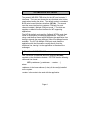
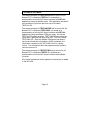
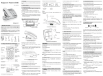
1.1 CARD INSTALLATION
The IdFi card can be installed in any 8- or 16-bit slot on any
IBM-PC or compatible (including EISA-equipped) computer.
Multiple cards can be installed as long as the base addresses
are set to different values. Consult the diagram below for
jumper locations:
LINE 0 & 1 IN
LINE 2 & 3 IN
LINE 0 & 1 OUT
LINE 2 & 3 OUT
1
0
H12
H10
01234567
H3B
H3
Page 1
The base address of the card is set using H12 and H10 as per
the following table:
H10 Jumper
Position
0
1
2
3
4
5
6
7
H12 Position 0
H12 Position 1
200 (factory
default)
220
240
260
280
2A0
2C0
2E0
600
620
640
660
680
6A0
6C0
6E0
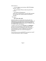
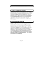
1.2 TELEPHONE SYSTEM INTEGRATION
The IdFi card is connected to the phone line via several
standard modular phone sockets. Each socket services two
telephone lines. On any given plug, the red/green (inner) wire
pair represents the lower line number of the two lines and the
black/yellow (outer) pair represents the higher line number.
Thus the inner pair on the first modular socket from the top is
the input to line 0 of the card and the outer pair on the fourth
socket from the top is the output from line 3 of the card.
Consult the diagram below for clarification.
Modular Plug
Line 0 or 2
Line 1 or 3
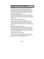
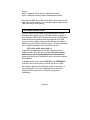
To integrate the IdFi card to a phone system, a pair of lines
from the network should be placed on one of the inputs of the
Page 2
card and then that same pair of lines should be connected from
the corresponding card output to the rest of the telephone
system. Thus, two lines from the network would be connected
to the first modular socket from the top and would then continue
to the rest of the telephone system from the third modular
socket from the top of the card.
The following figures illustrate connection examples.
IdFi
Card
Line 0 ( Red / Green )
Line 1 ( Black / Yellow )
Line 2 ( Red / Green )
Line 3 ( Black / Yellow )
Voice
Card
VOICE CARD APPLICATION ( 4 LINES )
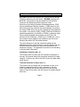
(
IdFi
Card
Line 0 ( Red / Green )
TELEPHONE APPLICATION ( 1 LINE )
Page 3
2.0 MS-DOS SOFTWARE
The powerful MS-DOS TSR driver for the IdFi card contains 3
interfaces. The user can choose the one that best suits his/her
needs when loading the driver. The default mode is a standard
BIOS serial communications interface (INT14h). The second
uses the same interface but creates a COM port for each
channel installed ( Multiple COM port mode ). The third one
supplies a callback function interface for IdFi-supporting
applications.
The INT14h default mode and the Callback INT2Fh mode feed
Caller-ID information to underlying applications. They do so
using a well-defined format which alleviates the application from
having to decode the many different Caller-ID message formats
available. The INT14h Multiple COM port mode feeds the
application with the information coming directly from the
telephone line, leaving it to the application to decode all the
messages.
2.1 LOADING THE SOFTWARE
The TSR driver is contained within the program IDFI.EXE
supplied on the distribution diskette. IDFI.EXE has the following
command line format:
IDFI -p<address> [-p<address> . -<mode>. . .]
where
<address> is the base address (in hex) of the card(s) installed
on the system.
<mode> is the mode to be used with the application.
Page 4
Valid modes are
- c for the Callback mode interface ( MS-DOS Multiplex
Services , INT2Fh )
- m for the Multiple COM port mode using the INT14
interface.
- w to install the Windows driver.
When there is no mode option on the IDFI.EXE command
line, the default INT14 Serial interface for MS-DOS is
activated.
Thus typing:
IDFI -p200 -p220 -p240
will load the driver to communicate with cards at the base
addresses 200, 220 and 240 with the default INT14 interface. It
is vital that the base addresses be correctly specified on
the command line! Behavior of the driver is undefined if there
is no card at a given base address.
In addition to the driver, the files IDFI.A07 and PDOWN.A07
must be in the current directory to allow the driver to load.
Note that the process of initializing the card is fairly slow. A
"percentage done" counter is displayed by the driver as it
executes to allow the user to monitor the progress of
initialization.
Once the driver returns to the MS-DOS command line, the IdFi
is active and looking for Caller-ID messages.
Page 5
2.2 USING THE INT 14H DEFAULT INTERFACE
IDFI.EXE intercepts the BIOS INT 14h handler and pretends to
be "COM5" (device 4) when the driver is being used in the
default INT14 mode. Any calls for COM1, COM2, COM3 and
COM4 are passed transparently to the BIOS (or FOSSIL or
whatever other communications handlers are hooked onto INT
14h). Calls for COM5 services are handled by the IdFi driver.
Initialization Function (AH = 0)
This function does not affect the IdFi software or hardware in
any way. All returned status bits are zeroed except for the data
ready bit. If there is any data in the IdFi's queue, the data ready
bit will be set.
Transmit Character Function (AH = 1)
This function will do nothing and is considered an error. If an
underlying application tries to send a character to the IdFi
driver, it will simply set the time-out error bit in the returned
status. If there is any data in the IdFi's queue, the data ready bit
will be set.
Receive Character Function (AH = 2)
This function will return the next character in the IdFi's queue if
there is any data to retrieve. Further, if there is more data to
receive after pulling the current piece, the data ready bit will be
set. If there is no character waiting, the time-out error bit will be
set to flag the error condition.
Get Serial Status Function (AH = 3)
This function will return with all status bits cleared with the
possible exception of the data ready bit. If there is data waiting
in the IdFi's queue, the data ready bit will be set.
Page 6
2.3 USING THE INT 14H MULTIPLE COM PORT
INTERFACE
IDFI.EXE used with the command line -m provides the Multiple
COM port interface to the IdFi driver. IDFI.EXE intercepts the
BIOS INT 14h handler as with the default INT14h interface.
There are two differences with the previous mode:
Each line on the Caller ID boards will be assigned one “COM”
port by the Multiple COM port interface. COM5 (device 4) will
be the first line of the card with the lowest address, the second
line being COM6 and so on up to the number of lines installed in
the system. Any calls for COM1, COM2, COM3 and COM4 are
passed transparently to the BIOS (or FOSSIL or whatever other
communications handlers are hooked onto INT 14h). Call
services for the COM ports ( COM5, line 0, COM6, line 1 up to
the number of lines installed.) are handled by the IdFi driver
following the default INT14h mode interface.
The other difference is that the information passed to the
application will be in a binary format. It comes directly from the
line and represents exactly the information provided by the
telephone company. The application must do its own decoding
to extract useful information.
Initialization Function (AH = 0)
This function does not affect the IdFi software or hardware in
any way. All returned status bits are zeroed except for the data
ready bit. If there is any data in the IdFi's queue, the data ready
bit will be set.
Transmit Character Function (AH = 1)
This function will do nothing and is considered an error. If an
underlying application tries to send a character to the IdFi
driver, it will simply set the time-out error bit in the returned
status. If there is any data in the IdFi's queue, the data ready bit
will be set.
Page 7
Receive Character Function (AH = 2)
This function will return the next character in the IdFi's queue if
there is any data to retrieve. Further, if there is more data to
receive after pulling the current piece, the data ready bit will be
set. If there is no character waiting, the time-out error bit will be
set to flag the error condition.
Get Serial Status Function (AH = 3)
This function will return with all status bits cleared with the
possible exception of the data ready bit. If there is data waiting
in the IdFi's queue, the data ready bit will be set.
Page 8
2.4 USING THE CALLBACK INTERFACE
IDFI.EXE used with the command line -c provides the callback
interface to the IdFi driver. To access this functionality, the
following protocol through INT 2Fh is used:
Function 0 -- Register Application
Call With
AX
= 0CDCDh
BX
= 0000h
DS:SI = pointer to signature string
"PIKA IDFI"
ES:DI = pointer to callback function
(detailed below)
Returns With
AX
= 0CDCDh
BX
= 0FFFFh
DS:SI = pointer to signature string
"Registered"
*** Important Note: All signature strings must be NULL
terminated! ***
This function registers an application's callback entry point with
the IdFi driver. After this function call is issued, the IdFi driver
will call the application's callback function whenever it has a
CLID message available. When it makes its call, it will have the
following register values:
AX
=
BX
=
CX
=
DS:SI =
0CDCDh
0FFFEh
Message length in bytes
Far pointer to message buffer
The callback function must copy the supplied message into its
own RAM space as the IdFi driver will assume that the buffer is
free when it returns from the callback function. Since the
callback function is called asynchronously, it may not make use
Page 9
of any MS-DOS or BIOS services unless it has taken
appropriate precautions.
Function 1 -- De-register Application
Call With
AX
= 0CDCDh
BX
= 0001h
DS:SI = pointer to signature string
"PIKA IDFI"
Returns With
AX
= 0CDCDh
BX
= 0FFFEh
DS:SI = pointer to signature string
"De-registered"
*** Important Note: All signature strings must be NULL
terminated! ***
This function de-registers the application's callback entry point.
It must be called before the application can terminate. Failure
to de-register the application will result in unpredictable
(and possibly destructive) system performance.
Page 10
2.5 RETURNED DATA FORMAT
The IdFi driver returns information to the application in the
following 72-byte format, one byte at a time when using the
default INT 14h mode or with a pointer to the entire block when
using the callback mode functions. Note that all data is in ASCII
printable format.
byte 0
board number from 0 to F (lowest address = 0)
byte 1
line number on board from 0 to 3
bytes 2-6
spaces
bytes 7-11
date (mm/dd)
bytes 12-16
spaces
bytes 17-21
time (hh:mm)
byte 22
space
bytes 23-24
AM or PM
bytes 25-29
spaces
bytes 30-43
telephone number (left filled with spaces), or
OUT OF AREA (left filled with spaces), or
PRIVATE (left filled with spaces)
bytes 44-48
spaces
byte 49
0 if call is local or 1 if call is long distance. If
the card receives a single message format, the
length of the phone number will determine if it
is a long distance call.
bytes 50-54
spaces
bytes 55-69
caller name (left filled with spaces)
byte 70
ASCII carriage return
byte 71
ASCII line feed
Any fields which are not valid or which have no information
supplied are filled with spaces (in keeping with the printable
nature of the returned data).
Page 11
2.6 SAMPLE SOFTWARE
The sample program file TEST14.EXE and its source file (for
Borland C/C++ compilers) TEST14.C is included as a
demonstration of how the IdFi driver interfaces with INT 14h
applications using the default mode. This application also writes
the information it gets from the driver into a file called
TEST14.LOG.
The sample program file TEST14M.EXE and its source file (for
Borland C/C++ compilers) TEST14M.C is included as a
demonstration of how the IdFi driver interfaces with INT 14h
applications using the Multiple COM port mode. As with the
TEST14.EXE sample program, TEST14M.EXE also writes the
information it gets from the driver into a file. This file is called
TEST14M.LOG. Since the Multiple COM port mode doesn’t
convert and format the information in ASCII characters, the
information contained in the TEST14M.LOG is in a binary
format. You will need an editor that supports binary format to
view the content of it.
The sample program file TEST2F.EXE and its source file (for
Borland C/C++ compilers) TEST2F.C is included as a
demonstration of how the IdFi driver interfaces with callback
functions.
All of these applications will be updated as functionality is added
to the IdFi card.
Page 12
3.0 WINDOWS SOFTWARE
3.1 PIKA IDFI DDE SERVER OVERVIEW
The IdFi DDE Server is a Windows application that interacts
with the Pika IdFi card to provide caller identification via DDE or
Windows messages. It will allow applications written in macro
languages such as Microsoft Excel and Microsoft Word for
Windows to receive caller id without requiring special libraries.
It will also allow applications written in C or other high level
languages to receive caller id data through a windows
message, without having to worry about the complexities of
DDE messaging.
3.2 PIKA IDFI DRIVER OPERATION
The IdFi Windows driver consists of two parts, a DLL and the
DDE Server. The DLL is used to allow applications to register
with the IdFi server without having to use DDE messaging.
Applications can receive caller id information through their
window procedure by registering with the DLL, or they can
register with the DDE Server to receive DDE messages. The
application is notified using the appropriate message type
whenever new caller id information is received by the IdFi card.
To inform the DDE server about the addresses used by the
cards, you must enter them into the PCLID.INI file. This file is
then placed this file in your Windows directory. The format of
the PCLID.INI file is the following:
Page 13
[ports]
port1 = (address of first card in hexadecimal format)
port2 = (address of second card in hexadecimal format)
Note that the DDE Server will not be able to detect that the IdFi
card has not been loaded. If it is not operating as expected, the
card most likely needs loading.
3.3 LOADING THE IDFI CARD
The IdFi card must be loaded and initialized before running
Windows. We suggest you run IdFi.EXE with the -w option in
your autoexec.bat file. IdFi.EXE can be run from a DOS prompt
under Windows, but loading times are extended. The DDE
Server will not be able to communicate with the card until it is
loaded using IdFi with the Windows option. A typical command
line to load the Windows driver would look like this:
IDFI -p200 -p220 -p240 -p600 -w
Typing this will load the driver into the cards at the base
addresses 200, 220, 240 and 600. It is vital that the base
addresses be correctly specified on the command line!
Behavior of the driver is undefined if there is no card at a given
base address.
In addition to the driver, the files IDFI.A07 and PDOWN.A07
must be in the current directory to allow the driver to load.
Note that the process of initializing the card is fairly slow. A
"percentage done" counter is displayed by the driver as it
executes to allow the user to monitor the progress of
initialization.
Page 14
3.4 USING DDE
Windows application programs using the PIKA IdFi DDE Server
should be structured in the following way.
The application must first open a DDE channel to the DDE
Server using DDE Initiate, using the application "IDFI" and topic
"Info". The IdFi DDE server responds to the items . The
application may now set up hot links (sometimes called ADVISE
sessions) to the items "AllData" or "NameNumber". A
DDE_DATA message containing caller id information will then
be sent to the application whenever an incoming call with caller
id information occurs on this line. The item "AllData" will supply
a complete set of information, including date and time. The item
"NameNumber" will provide the name and number of the caller
only.
Note that the data returned when the link is first made will be
the data returned from the last call, if there has been one since
the card was loaded, or a blank string otherwise.
Terminate any open DDE links before closing the application.
DDE Message format:
"AllData" item:
<channel>:<number>:<name>:<type>:<date>:<time>:<ampm>
"Number" item
<channel>:<number>:<name>
Each field is separated by colon and has a fixed length.
Page 15
Field descriptions:
<channel>
2 numeric digits, the first is the board number, the second is
the line number from 0 of that board. Boards are numbered
according to their port address.
<number>
14 character digits containing the calling number. If the
number is less than 14 characters, it is left padded with
spaces.
<name>
15 characters containing the name. If the name is not
supplied, or less than 15 characters, it is left padded with
spaces
<type>
a single character defining the type of message, 0 for local,
1 for long distance.
<date>
6 characters containing the date of this call in the format
mm/dd.
<time>
5 characters containing the time of this call in the format
hh:mm.
<ampm>
2 characters, either 'AM' or 'PM'
Page 16
3.5 USING THE DLL
The DLL exports two functions:
pika_IdFi_register and pika_IdFi_deregister.
The functions are declared as:
int far pascal pika_IdFi_register(HWND hwnd);
int far pascal pika_IdFi_deregister(HWND hwnd);
Both functions return 0 if successful.
Windows application programs must register with the DLL using
the function pika_IdFi_register. The application must supply a
window handle which is to receive the caller id messages.
The IdFi DDE Server must be running, even if the DDE is not
being used. The DDE Server polls the IdFi card is for incoming
messages, and sends pika_IdFi_event messages to all
registered applications. If the DDE Server is not running, the
application will not receive caller id information.
When the DDE Server receives caller id information, it will send
a windows user message to each registered application. The
application can then retrieve the caller id data using the pointer
supplied as part of the message. The windows message type is
dynamically allocated using RegisterWindowsMessage with the
string "PIKA_IDFI_MSG". This ensures that there will not be a
message conflict with any other applications.
Applications should ensure that they call pika_IdFi_deregister
before terminating.
Page 17
IdFi Message format:
Message type:
return value from RegisterWindowsMessage("IdFi");
wParam:
channel
lParam:
far pointer to a TCI_message struct:
struct {
char
line[2];
/* 0 = board, 1 = line number */
char
spaces1[5];
char
date[5];
char
spaces2[5];
char
time[5];
char
spaces3;
char
am_pm[2];
char
spaces4[5];
char
number[14];
char
spaces5[5];
char
type;
char
spaces6[5];
char
name[15];
/* left filled with spaces *
char
cr_lf[2];
/* 0 = CR, 1 = LF */
/* 0,1 = mm, 2 = '/', 3,4 = dd */
/* 0,1 = hh, 2 = ':', 3,4 = mm */
/* "AM" or "PM" */
/* left filled with spaces */
/* '0' = local, '1' = long distance */
} TCI_message;
Page 18
3.6 WINDOWS DRIVER CONTENTS
The following are the IdFi Windows files. Windows must be
able to find the DLL using its normal search algorithms. The
directory must be the current directory when the application is
launched, or in the Windows directory, or in the DOS path.
IDFIDDE.EXE
the IDFI DDE Server application.
IDFI.DLL
this is the Dynamic Link Library used by the DDE Server. It
should be in your DOS path.
IDFIDLL.LIB
this file should be linked with your application if using the
DLL. It will ensure that Windows loads the DLL when you
run your application.
IDFIDLL.H
contains the C style function definitions for
pika_IdFi_register and pika_IdFi_deregister.
IDFICLNT.EXE
A DDE client application that can be used to test and
monitor the IdFi interface. Visual Basic source code is
provided in the directory IDFICLNT.
IDFIMON.EXE
a C program that uses the Windows message interface.
Source code is provided in the directory IDFIMON.
Page 19