1
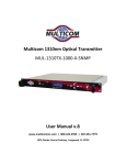
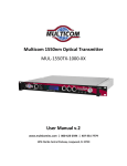
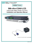
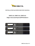
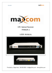
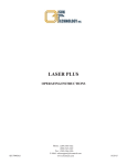
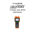
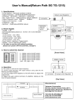
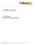
Multicom Optical Return Path Receiver MUL‐HRPR‐4B User Manual v.9 www.multicominc.com | 800‐423‐2594 | 407‐331‐7779 1076 Florida Central Parkway, Longwood, FL 32750 Multicom Headend Return Path Receiver MUL‐HRPR‐4B SAFETY NOTIFICATION Multicom strongly advises you to read the following safety instructions prior to installing and operating this equipment. Read These Instructions First – All safety and operating instructions should be read before installing or operating this equipment. Retain This Instruction Manual – Safety and operating instructions must be retained for future reference. Ventilation – Do not block or cover openings in this equipment. These are provided for ventilation and protection from overheating. Maximum operating ambient temperature is 122°F (50°C). Power Sources – All power must be provided via a three wire, grounded power supply and cord. The mains circuit should be a dedicated, unswitched supply. Keeps the unit away from high voltage or other interference creating devices such as motors, compressors, etc. Grounding or Polarization – This equipment is equipped with a polarized AC line plug. This plug will fit into the power outlet only one way. This is a safety feature. Do not defeat the safety purpose of a polarized plug. This equipment must installed and grounded per NEC regulations. CAUTION: For continued protection against risk of fire, replace circuit breakers/fuses (if necessary) with one of only the same type and rating. © 2010 Multicom, Inc. www.multicominc.com (800) 423‐2594 | 407‐331‐7779 Page 2 Multicom Headend Return Path Receiver MUL‐HRPR‐4B Table of Contents 1.0 PRODUCT DESCRIPTION 2.0 PRODUCT FEATURES 3.0 BLOCK DIAGRAM 4.0 HEADEND RETURN PATH RECEIVER LAYOUT 4.1 Front Panel Layout 4.2 rear Panel Layout 5.0 CONTROLS, INDICATORS, AND ALARMS 5.1 Front Panel Operation 5.2 Start‐up Main Menu 5.3 Unit Configuration Instructions 5.3.1 Changing IP Address Settings 5.3.2 Attenuation Adjustment 6.0 OPERATION NOTICE 7.0 WARRANTY AND REPAIR 8.0 TECHNICAL SPECIFICATIONS © 2010 Multicom, Inc. www.multicominc.com (800) 423‐2594 | 407‐331‐7779 Page 3 Multicom Headend Return Path Receiver MUL‐HRPR‐4B 1.0 PRODUCT DESCRIPTION The Multicom MUL‐HRPR‐4B Optical Return Path Receiver is ideally suited for use in optical headends in HFC and FTTH and many other fiber optic‐based data, video, and voice networks, including Broadband Stimulus and FCC National Broadband projects and applications, and provides a cost effective solution. The MUL‐HRPR‐4B’s state‐of‐the‐art features include an industry‐leading 4 port, typical +25dBmV individually adjustable RF outputs, 5 ‐ 200MHz return bandwidth, wide optical input range down to ‐9dBm, and a unique backlit front panel control display ‐ all in a temperature‐controlled, 1 RU rack‐mount chassis. 2.0 PRODUCT FEATURES Wide optical Input Range 1200 ‐ 1620nm Typical +25dBmV adjustable RF output for each of the 4 ports 5 ‐ 200MHz return bandwidth Four receivers in 1RU unit Wide optical input range and low noise design allows error free detection down to ‐9dBm Configuration and status monitoring on the easy‐to‐view backlit front panel display Housing temperature is displayed, monitored, and controlled by the micro‐processor Optional factory installed SNMP 3.0 BLOCK DIAGRAM Figure 1 – Block Diagram © 2010 Multicom, Inc. www.multicominc.com (800) 423‐2594 | 407‐331‐7779 Page 4 Multicom Headend Return Path Receiver MUL‐HRPR‐4B 4.0 HEADEND RETURN PATH RECEIVER LAYOUT 4.1 Front Panel Layout Figure 2 – Front Panel 1. LCD screen (see 4.1 for menu operation) LCD menu select button 2. LCD menu up/down button 3. Power LED – On when lit 4. ATT – Turning the potentiometer clockwise increases RF output, turning the potentiometer counter clockwise decreases RF output 5. Green LED when +1dBm ≥ OPT IN > ‐13dBm, OPT IN >+1dBm red LED alarm lit, LED turned off when Optical Input drops below ‐13dBm. Numbers 5 and 6 pertain to all four receivers. 4.2 Rear Panel Layout Figure 3 – Rear Panel 1. Receiver 1 2. Fiber Optic Input – SC/APC Connector 3. ‐12dB RF Test Point – F Connector 4. RF Output – F Connector 5. RS232 Control Port © 2010 Multicom, Inc. www.multicominc.com (800) 423‐2594 | 407‐331‐7779 Page 5 Multicom Headend Return Path Receiver MUL‐HRPR‐4B 6. Power Receptacle 7, 8, 9. Receivers 2, 3, and 4 5.0 CONTROLS, INDICATORS, AND ALARMS This section of the manual will give an overview of the available menus in the Multicom MUL‐HRPR‐4B Headend Return Path Receiver and their descriptions. All instructions in this section refer to the front panel shown in Figure 2. The user scrolls through the menus using the push buttons found on the front panel, these are located just to the right of the LCD screen. 5.1 Front Panel Operation With the power source turned on (power switches are located at the rear of the unit) and the unit working properly, the digital panel will display MULTICOM, INC. on line 1 and the Multicom phone number 1‐407‐331‐7779 on line two. 5.2 Start‐up Main Menu Pressing the Select button will scroll through the menu sequence below. Line 1 will always read: MUL‐HRPR‐4B: Menu #1 – Descriptor Line 1: Read‐only menu, model of this equipment Line 2: Read‐only menu, serial‐number Menu #2 – Input #1 Read‐only menu, displays the input optical power of Receiver #1 in dBm Menu #3 – Input #2 Read‐only menu, displays the input optical power of Receiver #2 in dBm Menu #4 – Input #3 Read‐only menu, displays the input optical power of Receiver #3 in dBm Menu #5 – Input #4 Read‐only menu, displays the input optical power of Receiver #4 in dBm Menu #6 – Unit temp Read‐only menu, displays the unit temperature in °C © 2010 Multicom, Inc. www.multicominc.com (800) 423‐2594 | 407‐331‐7779 Page 6 Multicom Headend Return Path Receiver MUL‐HRPR‐4B Menu #7 ‐ +5V Reads Read‐only menu, displays the actual output voltage from the +5V supply Menu #8 ‐ ‐5V Reads Read‐only menu, displays the actual output voltage from the ‐5V supply Menu #9 – +12V Reads Read‐only menu, displays the actual output voltage from the +12V supply Note: Menu items 10‐14 apply only to units with factory installed optional SNMP Menu #10 – IP Selectable menu: Displays the IP address for the SNMP Network Interface. Menu # 11 – SUBMASK Selectable menu: Displays the default IP address for the SNMP Network Interface Menu # 12 – GATEWAY Selectable menu: Displays the default gateway address for the SNMP Network Interface Menu # 13 – Trap Addr 1 Selectable menu: Displays the default trap address 1 for the SNMP Network Interface Menu # 14 – Trap Addr 2 Selectable menu: Displays the default trap address 2 for the SNMP Network Interface 5.3 Unit Configuration Instructions 5.3.1 Changing IP Address Settings Menu items 10 – 14 require the factory installed SNMP option. To change the IP address in any of these menu items 1. 2. 3. 4. 5. Use the Select button to scroll to Menu # 10 – 14 Press to move the cursor through the octets of the IP address Stop in the field that you want to change Press the to change the number Press Select to leave the current menu item and move to the next menu item 5.3.2 Attenuation Adjustment The RF output level is proportional to the optical input level. The RF output level is 20dBmV at minimum attenuation with ‐9 dBm input power and 20% OMI . Balancing the © 2010 Multicom, Inc. www.multicominc.com (800) 423‐2594 | 407‐331‐7779 Page 7 Multicom Headend Return Path Receiver MUL‐HRPR‐4B output of the RF level between receivers can be accomplished by using the ATT potentiometer for each receiver. ATT (5, Figure 2) – Turning the potentiometer clockwise increases RF output, turning the potentiometer counter clockwise decreases RF output. 6.0 OPERATION NOTICE Changes to IP settings will be retained on power down/up. Use only Single Mode Fiber (SMF) optic cable (9/125µM). Multi‐Mode Fiber (MMF) is incompatible with the equipment and will result in unacceptable performance and possible damage to the equipment. All fiber splices should be fusion‐type splices. Avoid mechanical or compression type connections. For optimum performance, fiber runs should be made directly from the transmitter to the receiver. Minimize the use of adapters, patch panels, and additional points of failure and signal loss. In order to ensure good return loss, use only SC/APC connectors. Clean and inspect connectors and fiber end faces prior to installation, and every plug in/out cycle. Use only industry approved methods, materials, and solutions for cleaning. 7.0 WARRANTY AND REPAIR The Multicom MUL‐HRPR‐4B Headend Return Path Receiver has a one year warranty and is subject to Multicom’s standard warrantee terms. There are no user serviceable components inside the unit. The warranty is void if the unit is opened or is damaged due to misuse. © 2010 Multicom, Inc. www.multicominc.com (800) 423‐2594 | 407‐331‐7779 Page 8 Multicom Headend Return Path Receiver MUL‐HRPR‐4B 8.0 TECHNICAL SPECIFICATIONS General Optic RF Specifications Operating temp (ºC) Storage temp (ºC) Operating relative humidity (%) Power supply – 9 Volt AC Power consumption (W) Size (WxDxH in inches) Interface port Wavelength (nm) Responsivity (A/W) Input power level (dBm) Return loss (dB) Output fiber connector RF bandwidth (MHz) RF output level (dBmV) RF gain adjustment range (dB) Flatness (dB) Return loss (dB) RF connector NPR dynamic range (dB) Values 0 – 50 ‐40 – 85 5 – 95 100 – 240 24 19x12x1.75 RJ45, RS232 1200 – 1620 0.85 ‐9 – +1 50 SC/APC 5 – 200 15‐35 ‐15 – 0 ‐0.75 – +0.75 16 F type 24 Notes 32 – 122 ºF Non‐condensing 4 receivers At 1310nm +25 typical Front panel 75Ω impedance @‐9dBm, 30dB © 2010 Multicom, Inc. www.multicominc.com (800) 423‐2594 | 407‐331‐7779 Page 9