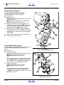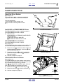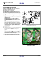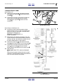
1
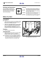
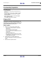
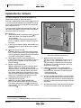
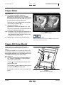
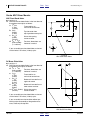
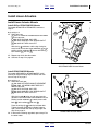
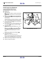
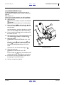
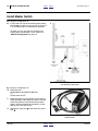
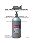
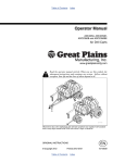
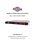
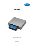
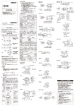
Parts
Great Plains Mfg., Inc.
Installation Instructions
1
Air Drill Variable Rate Kit
Air Drill Carts and 6 & 9m Air Drills
Used with:
• ADC2350, ADC2350B
• NTA907HD, NTA3007HD
• NTA607HD, NTA2007HD
General Information
These instructions explain how to install a variable rate
controller on a compatible air cart or integrated air drill
that presently has only manual (crank-operated) rate
control. With Variable Rate installed, the seed monitor
directly controls material rate, independently, at each
updated meter.
These instructions apply to an installation of:
Kit
166-193A
166-328A
166-339A
Kit Description
ADC2350 VARIABLE RATE KIT (dual)
VARIABLE RATE ACTR KIT SGL BIN
VAR RATE ACTR KIT DUAL BIN
These kits apply to:
Cart or Drill
ADC2350a
ADC2350Ba
NTA607HD
NTA907HD
NTA2007HD
NTA3007HD
U
Kit Compatibility
B
R
166-193A
166-193A
166-328A orb 166-339A
166-193A
166-328A orb 166-339A
166-193A
F
D
L
Figure 1
166-193A Kit Installation
a Drills with software version prior to 4.21 require the software
update included in this kit. See page 4.
b A single hopper drill uses the 166-328A kit. A dual hopper drill
may use either 166-328A or 166-339A, depending on whether
variable rate is desired for just one or both meters.
One “dual” kit includes two actuators, and updates one
air cart or one integrated air drill. One “sgl” (single) kit
includes one actuator and updates one meter.
The 166-193A kit includes new WSMT software for older
ADC2350/B air carts that have a Software Version that
lacks qualified variable rate support.
29498
Related Documents
110011512
110011513
11001-1507
167-085B
ACC User Manual, Levels 2 and 3
ACC User Manual, Level 1
Version 4 Software Update Guide
Seed Rate Manual (ADC & NTA models)
Have the Operator Manual at hand for drill movements.
167-085M
166-207M
166-283M
Operator, ADC2350/2350B
Operator, NTA907/3007HD
Operator, NTA607/2007HD
Have the current Parts Manual at hand for parts ID.
167-085P
166-207P
166-283P
6/23/2010
©Copyright 2010
Parts, ADC2350/2350B
Parts, NTA907/3007HD
Parts, NTA607/2007HD
166-263M
2
Air Drill Variable Rate Kit
Front
Notations and Conventions
“Left” and “Right” are facing in the
direction of machine travel. An orientation rose in the line art illustrations
shows the directions of Left, Right,
Front, Back, Up, Down.
Parts
Great Plains Mfg., Inc.
Call-Outs
U
B
R
F
D
L
1
to
9
11
to
40
51
to
52
Single-digit callouts identify components in
the currently referenced Figure or Figures.
These numbers may be reused for different
items from page to page.
Two-digit callouts in the range 11 to 40 reference new parts (see list on page 20).
Two-digit callouts in the range 51 to 52 reference affected existing parts (see page 21).
Before You Start
Compatibility
Refer to Figure 2
1. Check that linear actuators are not already installed
on the cart or integrated air drill. Variable Rate is a
feature that can be factory-installed.
2.
Check the model number of the air cart or air drill to
ensure it is a compatible model. For example, this
kit is not compatible with the gearboxes used on
ADC1150, ADC2220 or ADC2250 air carts, nor
NTA1000, NTA1300 or NTA2000 integrated air drills.
Inventory
3.
Make sure all parts are present.
Comprehension
4.
Review these instructions. Make sure the installers
understand where each part or assembly is
installed, and what tools are required for the task.
Note: Illustrations in this manual, based on implement
Parts manual, may show exploded views that are
fully disassembled. Rely on the instructions for
required disassembly and reassembly steps.
166-263M
Front
Figure 2
ADC Model/Serial Number Plate
Parts
26428
6/23/2010
Great Plains Mfg., Inc.
Front
Parts
Installation Instructions
3
Pre-Assembly Preparation
Tools Required
• suitable tractor for positioning and operating the air
drill or cart
• the seed monitor console to be used with this implement (or a 2008 or later DICKEY-john® IntelliAG®
10in LCD console)
• basic hand tools, including (for older ADC2350/B
only), a drill with bit size:
1⁄ in (0.250in), letter size E, or 6.3mm
4
Prepare Drill
The mechanical installation may be performed on a disconnected air cart, but software update (if required), and
testing/configuration of the system require the complete
air drill, and an IntelliAG® virtual terminal.
Work Location
5.
Move the air cart or air drill to a location with:
• room to fold it (NTA607/2007HD and NTA907/
3007HD only);
• access to tractor or hydraulic power;
• access to DICKEY-john® IntelliAG® console and
12Vdc power;
• adequate illumination; and,
• clear surface beneath for recovery of any falling
or dropped parts - if the surface is not clear, have
a tarp or drop cloth available.
6.
NTA607/2007HD and NTA907/3007HD only:
Fold drill. Lower openers. This eases access to the
meters.
7.
Shut off tractor or hydraulic source.
6/23/2010
Front
Parts
166-263M
4
Air Drill Variable Rate Kit
Front
Parts
Great Plains Mfg., Inc.
Update Monitor Software
For models NTA607HD, NTA907HD, NTA2007HD or
NTA3007HD, continue at step 18 on page 5.
This step is performed first in the unlikely event that there
is any incompatibility between your IntelliAG® virtual terminal, and the latest version of the Air Cart Control software supplied in the kit.
2
If you are unable to update the seed monitor system, do
not continue the update. Have your Great Plains dealer
contact the factory for assistance.
3
Refer to Figure 3
8. Check the seed monitor Software Version 1 per the
11001-1507 guide. If the Software Versiona is:
4.21 or higher,
you do not need to update the seed monitor software. If no update is required, continue at step 18
on page 5.
37
9.
1
If you require a software update, and the SD card is
missing from the kit, contact Great Plains to obtain
the update.
10. Select from the kit one new:
38 11001-1507 ACC V4 SOFTWARE REPROGRAMMING
This is a DICKEY-john® manual describing the process of updating the software for the virtual terminal
(if needed) and the WSMT (if needed).
11. Follow the instructions in the reprogramming
manual 38 to check the VT part number (on back of
terminal) and the software version of your seed
monitor (icon 2 ).
12. Record Current Configuration
Monitor configuration may reset to defaults during
update. If either VT or WSMT will be updated,
record the current air drill configuration, particularly
the Material Library. Although newer virtual terminals support exporting the configuration to a blank
SD card, Great Plains recommends making a paper
record, as an imported SD configuration may be
altered during Auto Config at step 79.
13. Select from the kit one new:
37 INTELLI-AG SOFTWARE UPDATE SDC
This is a small Secure Digital (SD) flash memory
card. When instructed, the card 37 is inserted in a
slot at the lower right corner of the VT bezel, behind
a flip-up door 3 .
Figure 3
10in Virtual Terminal and SD Card
29504
14. Select one each new from the kit:
12 110011512 ACC USR MANUAL VER 4.2 LVL 2&3
13 110011513 ACC USER MANUAL VER 4.2 LVL 1
The new software introduces user access levels,
and requires a password, described in the Password Access manual 13 .
15. Follow the instructions in the reprogramming
manual 38 . Software is already provided on a formatted SD card, so perform no steps calling for:
- media formatting or
- extranet downloading.
16. The new variable rate controller is not yet installed,
and will not be detected by the new software. After
installing the new hardware, a complete Setup/Configuration is performed starting on page 15 of these
instructions.
17. Shut down the monitor. Shut off the tractor ignition
(to assure that monitor circuits are powered off).
a. This is displayed as “Software Version” and is not the “O.S. Version” nor the “Bootloader Version”.
166-263M
Front
Parts
6/23/2010
Great Plains Mfg., Inc.
Front
Parts
Installation Instructions
5
Prepare Meters
Refer to Figure 4
18. At a variable rate gearbox, remove the:
52 805-032C PIN HAIR COTTER .148 WIRE
then use the existing control crank 3 actuator to set
the indicator to 0 on the 0-100 scale. This prevents
the jackscrew from obscuring the scale.
Adjust the final crank handle position to fully down,
and re-insert the cotter pin 52 .
51
52
19. Remove and save the:
51 805-065C PIN WIRE RETAINING 1/4 X 1 3/4
50
3
This pin is re-used at step 41 to couple the new control arm to the gearbox control shaft.
Note: Removing this pin de-couples the gearbox control
shaft from the manual adjustment system. If it is
ever necessary to revert to manual control, move
the pin back to the manual arm.
20. Repeat step 18 and step 19 for the other meter.
Figure 4
Existing (Manual) Meters
26306
Equipment Damage Risk:
Never operate the meters with pins in both the manual/crank
arm and the linear actuator arm.
Prepare ADC Driver Mounts
If your implement is an NTA607HD, NTA907HD,
NTA2007HD or NTA3007HD, continue at step 24 on
page 7.
4
On older ADC2350/B carts, the mounting holes for the
actuator driver modules may not be present, and must be
drilled. Newer ADC2350 carts, all NTA607/2007HD and
all NTA3007/907HD drills have holes present.
5
UF
L
Refer to Figure 5
21. Locate the mounting holes on the ADC2350/B air
cart. These are 0.28x0.38in (7.1x95mm) slotted
holes 5.84in (14.8cm) apart.
R
BD
One pair 4 is located on the forward break of the
gearbox mount plate.
The second pair 5 are located on the brace plate at
the center of the gearbox mount plate.
If these holes are present, continue at to step 24 on
page 7.
6/23/2010
Front
Figure 5
ADC Driver Mounting Holes
Parts
29508
166-263M
6
Air Drill Variable Rate Kit
Front
Parts
Great Plains Mfg., Inc.
Create ADC Driver Mounts
ADC Front Break Holes
Refer to Figure 6
22. Drill and size two slotted holes in the front break of
the gearbox mount plate as follows:
a 123⁄32in
Frame tool bar to
(1.72in)
vertical slot center-lines
(4.37cm)
b 9⁄16in
Top slot center from
(0.55in)
top of gearbox mount plate
(1.4cm)
27
c 5 ⁄32in
Slot to slot spacing,
(5.84in)
center to center
(14.8cm)
d 9⁄32 x 3⁄8in
Two slots, dimensions are
(0.28 x 0.38in)
horizontal x vertical
(7.1 x 95mm)
b
c
a
d
U
R
If you are unable to make slotted holes, make two
circular holes 5.75 inches (14.6cm) apart.
L
D
Figure 6
ADC Front Break Holes
29511
DC Brace Plate Holes
Refer to Figure 7
23. Drill and size two slotted holes in the front break of
the gearbox mount plate as follows:
d 9⁄32 x 3⁄8in
Two slots, dimensions are
(0.28 x 0.38in)
horizontal x vertical
(7.1 x 95mm)
e 13⁄4in
Frame tool bar to
(1.75in)
vertical slot center-lines
(4.4cm)
25
r 2 ⁄64in
Bottom of frame tool bar to
(2.39in)
upper slot center
(6.1cm)
v 329⁄64in
Bottom of frame tool bar to
(3.45in)
lower center to center
(8.8cm)
27
r+v 5 ⁄64in (5.84in) Slot to slot spacing,
(14.8cm)
center to center
e
r
v
If you are unable to make slotted holes, make two
circular holes 5.75 inches (14.6cm) apart.
If you are unable to make two holes without performing major disassembly of the gearbox structures, make only the top hole.
d
Figure 7
ADC Brace Plate Holes
166-263M
Front
Parts
29512
6/23/2010
Great Plains Mfg., Inc.
Front
Parts
Installation Instructions
7
Install Linear Actuators
Install Linear Actuator Mounts
Install ADC or NTA907/3007HD Mounts
7
For models NTA607HD or NTA2007HD, continue at
step 27.
Refer to Figure 8
24. Select one new:
29
17 168-371H LINEAR ACTUATOR MOUNT WELDMENT
32
and four sets new:
22 802-017C HHCS 3/8-16X1 GR5
32 804-013C WASHER LOCK SPRING 3/8 PLT
29 803-014C NUT HEX 3/8-16 PLT
22
With the lug 6 end down, and the lugs facing forward, install the actuator mount weldment 17 on the
existing anchor weldment 7 . Secure with bolts 22 ,
lock washers 32 and nuts 29 .
17
25. Repeat step 24 for the other meter.
6
26. Continue at step 37 on page 9.
Figure 8
ADC/NTA907/3007 Actuator Mount
29498
Install NTA607/2007HD Mounts
For models ADC2350/B or NTA907/3007HD, install
mounts per step 24 through step 25 above, then continue at step 37 on page 9.
14
8
Refer to Figure 9
27. Select one each new:
14 166-318H ACTUATOR MOUNT WELDMENT
21 800-238C .375 WIRING AND TUBE CLIP
and four sets new:
22 802-017C HHCS 3/8-16X1 GR5
32 804-013C WASHER LOCK SPRING 3/8 PLT
29 803-014C NUT HEX 3/8-16 PLT
32
29
9
21
22
With the lug end 8 facing up and away from the
gearbox, install the actuator mount weldment on the
existing anchor weldment 9 . Loosely secure with
bolts 22 , lock washers 32 and nuts 29 .
Place the wiring clip 21 under the left lower bolt.
Tighten the other three bolts to Grade 5 torque
spec. Leave the bolt with the clip finger-tight until
step 59 on page 12.
Figure 9
NTA607/2007 Actuator Mount
28. If two meters are being upgraded, repeat step 27 for
the other meter.
6/23/2010
Front
Parts
31357
166-263M
8
Air Drill Variable Rate Kit
Front
Parts
Great Plains Mfg., Inc.
Install Control Arm Weldments
Install ADC/NTA907/3007HD Arms
For NTA607/2007HD, continue at step 37.
Refer to Figure 10
29. Select one new:
16 168-370H ELECTRONIC CONTROL ARM WLDMNT
and two new:
40 890-202C GAUGE WHEEL SFT PIVOT BUSHING
30. Press one bushing 40 into the inside end 8 of the
control arm tube (the side with the longer arm with
indicator point).
8
Using the existing 1⁄4in holes in the tube as a guide,
drill a 1⁄4in hole through both sides of the bushing.
31. Press the other bushing
the control arm tube.
40
16
40
9
33
51
into the outside end of
32. With indicator tip to rear, and toward gearbox, place
arm weldment 16 assembly on control shaft 9 .
40
33. Select one saved:
51 805-065C PIN WIRE RETAINING 1/4 X 1 3/4
Align the arm tube 8 and inside bushing 40 with
the hole 9 in the gearbox control shaft. The arm
indicator tip should be pointing near “0” on the
scale.
Secure the arm with the wire retaining pin
Figure 10
ADC/NTA907/3007 Control Arm
29498
51 .
34. Select one each new:
33 805-021C PIN COTTER 1/4 X 2 PLT
Insert the cotter pin 33 through the end holes of the
gearbox control shaft. Spread tips to secure cotter.
35. Repeat step 29 through step 34 for the other meter.
36. Continue at step 45 on page 10.
166-263M
Front
Parts
6/23/2010
Front
Great Plains Mfg., Inc.
Parts
Installation Instructions
9
Install NTA607/2007HD Arm(s)
For ADC/NTA907/3007HD, install arms per step 29
through step 35 on page 8, then continue at step 45 on
page 10.
Refer to Figure 11
(which depicts an ADC installation - the NTA installations
have a different appearance but use the same instructions)
37. Select one new:
16 168-370H ELECTRONIC CONTROL ARM WLDMNT
and two new:
40 890-202C GAUGE WHEEL SFT PIVOT BUSHING
38. Press one bushing 40 into the inside end 8 of the
control arm tube (the side with the longer arm with
indicator point).
Using the existing 1⁄4in holes in the tube as a guide,
drill a 1⁄4in hole through both sides of the bushing.
39. Press the other bushing
the control arm tube.
40
51
33
9
16
into the outside end of
40. With indicator tip to rear, and toward gearbox, place
arm weldment 16 assembly on control shaft 9 .
40
41. Select one saved:
51 805-065C PIN WIRE RETAINING 1/4 X 1 3/4
Align the arm tube 8 and inside bushing 40 with
the hole 9 in the gearbox control shaft. The arm
indicator tip should be pointing near “0” on the
scale.
Secure the arm with the wire retaining pin
8
40
Figure 11
Install Control Arm
51 .
31358
42. Select one each new:
33 805-021C PIN COTTER 1/4 X 2 PLT
Insert the cotter pin 33 through the end holes of the
gearbox control shaft. Spread tips to secure cotter.
43. If two meters are being upgraded, repeat step 37
through step 42 for the other meter.
44. Continue at step 50 on page 10.
6/23/2010
Front
Parts
166-263M
10
Air Drill Variable Rate Kit
Front
Parts
Great Plains Mfg., Inc.
Install Linear Actuators
Install ADC/NTA907/3007HD Actuator
For NTA607/2007HD, continue at step 50.
9
Refer to Figure 12
45. Select one new:
39 833-456C LINEAR ACTUATOR 12V 8 IN 112LB
and two sets new:
35 805-397C PIN CLEVIS 1/4 X 1 23/64 USABL
34 805-307C PIN COTTER 3/32 X 1/2
8
46. With the cable end of the actuator 39 down, and
cable exiting up, align the lower operating rod of the
actuator with the lugs 17 in the mount weldment.
Secure with clevis pin 35 and cotter pin 34 .
16
34
47. Rotate the control arm weldment 16 as needed to
align the hole of the linear actuator rod with lugs 16
in new control arm. Secure with clevis pin 35 and
cotter pin 34 .
48. Repeat step 45 through step 47 for the other meter
35
49. Continue at step 52 on page 11.
39
34
35
17
Install NTA607/2007HD Actuator
For ADC2350/B or NTA907/3007HD, install actuators per
step 45 through step 48 above, then continue at
page 11.
Refer to Figure 13
50. Select one each new:
39 833-456C LINEAR ACTUATOR 12V 8 IN 112LB
23 802-167C HHCS 1/4-20X1 1/2 GR5
28 803-007C NUT-LOCK 1/4-20 PLT
Figure 12
ADC & NTA907/3007HD Actuator
28
39
With cable exiting down, secure the base end of the
actuator 39 between the ears 14 of the mount weldment. Thread the lock nut 28 onto the bolt 23 until it
contacts an ear, then back off one full turn.
51. Select one each new:
25 802-370C HHCS 1/4-20X1 3/4 GR5
28 803-007C NUT-LOCK 1/4-20 PLT
28
23
14
16
Secure the rod end of the actuator between the
arms 16 of the arm weldment. Thread the lock
nut 28 onto the bolt 25 until it contacts an arm, then
back off one full turn.
25
Figure 13
NTA607/2007HD Actuator
166-263M
29498
Front
Parts
31359
6/23/2010
Front
Great Plains Mfg., Inc.
Parts
Installation Instructions
11
Install Actuator Driver
About the Driver Module
1
24
Refer to Figure 14
The actuator driver 18 is an electronic module that
adapts the linear actuator to the IntelliAG® WSMT.
2
It has two cable leads:
1 2-pin lead to the linear actuator, and;
2 6-pin lead to the existing WSMT harness.
18
30
Figure 14
Actuator Driver Module
Install ADC or NTA907/3007HD Driver
29498
For NTA607/2007HD, continue at step 59 on page 12.
For NTA907/3007HD, continue at step 56.
4
52. Select two new:
18 464360033S1 G P ZEROMAX VALVE DRIVER
and four sets new:
24 802-274C HHCS 1/4-20X3 GR5
30 803-255C NUT HEX NYLOCK 1/4-20
5
UF
L
ADC 2350/2350B Driver Installation
R
For NTA907/3007HD, continue at step 56.
BD
Refer to Figure 15
On ADC2350/B, the driver modules mount vertically, with
the cable lead exiting from the bottom of the module.
53. Mount one driver 18 on the back side of the forward
gearbox mounting plate break, at the holes 4 identified or prepared at step 21.
Figure 15
ADC Driver Mounting
54. Mount the other driver 18 on the back side of the
gearbox brace plate, at the holes 5 identified or
prepared at step 21.
29508
55. Continue at step 62 on page 13.
NTA907/3007HD Driver Installation
Refer to Figure 16
On NTA907/3007HD, the driver modules mount horizontally, with the cable lead exiting from the rear of the module. The mount point is pairs of 1⁄4in (6.4mm)
holes ( 6 , 7 ), spaced 5.75in (14.6mm) apart, at the outside (right) top edge of the gearbox mount plate.
56. Mount one driver
18
at the forward hole pair
57. Mount the other driver
18
6
).
at the back hole pair
7
7
6
6
7
U
.
B
Figure 16
NTA907/3007 Driver Mounting
6/23/2010
Front
F
L
58. Continue at step 62 on page 13.
Parts
D
R
29509
166-263M
12
Air Drill Variable Rate Kit
Front
Parts
Great Plains Mfg., Inc.
Install NTA607/2007HD Driver
For ADC or NTA907/3007, install driver per page 11,
then continue at step 62 on page 13.
Refer to Figure 17 (a cut-away view)
On NTA607/2007HD, the driver modules mount vertically, with the cable lead exiting from the bottom of the
module. The module mounts to the rear face of the brace
plate 1 (as shown). The module side with four visible
studs 2 and nuts faces to cart right (away from cart).
U
F
L
B
59. Select one new:
18 464360033S1 G P ZEROMAX VALVE DRIVER
and two sets new:
26 802-804C HHCS 1/4-20X2 3/4 GR8 PLT
31 804-006C WASHER LOCK SPRING 1/4 PLT
27 803-006C NUT-HEX 1/4-20 PLT
D
27
31
1
R
2
18
26
Mount the driver module to the rear side of the
brace plate under the base end of an actuator (or
the actuator, if only one meter is being converted to
variable rate). Tighten the nuts and bolts only to
Grade 2 specification, to prevent deforming the
module housing.
18
Figure 17
NTA607/2007 Driver Mounting
Refer to Figure 18
60. Remove the bolt, clip 21 , washer and nut securing
the clip to the mount (installed at step 27 on
page 7).
31364
18
Route the two-pin lead 3 through the clip 21 . Resecure the clip to the weldment. Tighten fasteners
to no more than Grade 2 torque spec.
2
3
61. If two meters are being converted to variable rate,
repeat step 59 and step 60 for the other meter.
3
21
21
N ll4
166-263M
Front
Parts
Figure 18
NTA607/2007 Cable Clip
31363
6/23/2010
Great Plains Mfg., Inc.
Front
Parts
Installation Instructions
13
Connect Driver Leads
18
Refer to Figure 19
62. Connect the 2-pin lead 1 of the forward actuator
driver 18 to the 2-pin lead 2 of the forward linear
actuator 39 .
3
1
2
63. If two meters are being converted to variable rate,
connect the 2-pin lead 1 of the rear actuator
driver 18 to the 2-pin lead 2 of the rear linear
actuator 39
20
39
Figure 19
Actuator Driver Leads
29498
Figure 20
Harness Connection
29513
Refer to Figure 19 and Figure 20
64. Locate the harness connection points already
present on the air cart or air drill. The cables have
labels near the 6-pin connectors, and have labels
identifying the connectors as:
ZEROMAX 1 and ZEROMAX 2, or
FRONT and REAR
65. Remove dust caps from the connectors. The caps
are not re-used. If the harness connector leads are
coiled up and tied, and need to be uncoiled to reach
the driver module leads, cut the cable tie.
66. Connect the 6-pin lead 3 of the forward actuator
driver 18 to the 6-pin FRONT or #1 harness lead
4
.
67. If two meters are being converted to variable rate,
connect the 6-pin lead 3 of the rear actuator
driver 18 to the 6-pin REAR or #2 harness lead 5 .
68. Select all new:
20 800-060C CABLE TIE .19X14.25 3DIA 50LB
Use four ties to secure the leads for each actuator
and driver. The NTA gearbox mount plate provides 6
0.21in (5.3mm) holes for this purpose.
4
5
6/23/2010
Front
Parts
166-263M
14
Air Drill Variable Rate Kit
Front
Parts
Great Plains Mfg., Inc.
Install Master Switch
Refer to Figure 21 and Figure 22
69. In the tractor cab, locate the master switch connection lead 6 . On newer air carts and all air drills, this
is an un-terminated 2-pin weatherpak connector.
On older air carts, this lead may already have a
master switch connected to it. If so, continue at
“ACC Re-Configuration” on page 15.
6
19
Figure 21
Cab Harness Connection
29514
Refer to Figure 21 and Figure 22
70. Select one new:
19 467980124 ISO MASTER SWITCH
Set the switch to OFF.
19
71. Mount the switch near the monitor virtual terminal,
allowing enough cable length to reach the harness
connection located at step 69. Mount the switch
where it will be convenient for operations, but not
obstruct your view of the road.
72. Connect the 2-pin lead
lead 6 .
7
7
of the switch to harness
Figure 22
Master Switch
166-263M
Front
Parts
29505
6/23/2010
Great Plains Mfg., Inc.
Front
Parts
Installation Instructions
15
ACC Re-Configuration
Before first use, the new master switch and actuator outputs must be configured into the seed monitor system.
Depending on VT part number and previous software
revision, it may also be necessary to re-load basic air drill
parameters, and your local Materials Library.
Follow the instructions in the new IntelliAG® Aircart Control Operator’s Manual. The instructions below in this
manual are an overview of the sequence, and provide
cross-reference to information sources if you do not have
a complete record of the previous drill configuration.
Initial Power-Up Steps
29515
73. Check language and units preference.
74. Check/set date and time.
75. Perform an
Auxiliary Input/Function Assignment
This detects and assigns the new master switch.
76. If ON, set the new master switch to
OFF
(necessary to enter Configuration mode).
Load Drill Parameters
77. Enter System Mode:
Setup/Configuration
78. If the setup was lost during software update (or has
never been loaded), perform a
Module Configuration.
79. If you run an “Auto Config”, check the module
assignments against any record from step 12.
The new actuators are automatically detected by the
WSMT, and are not separately enumerated. When
present and connected, they enable the
“GRAN SEED/FERT CONTROL” modes hidden for
crank-adjusted drills.
Update Material Library
Example Material Library:
In order to correlate actuator output with desired seed
rate (meter shaft rate), the system requires a Calibration
Constant for each material to be used.
CH1
CH2
CH3
CH4
Wheat HRW
SEED 2
SEED 3
…
If you already had a material library, re-load it from an SD
card or via the menus. Otherwise revise a default material name as the first Control setup.
• The example at right shows sample materials:
Wheat HRW, renamed from SEED 1
and
11-52-0 renamed from FERT 1
to be used for the first Control setup.
6/23/2010
Front
Parts
Wheat HRW
11-52-0
DISABLED
DISABLED
11-52-0
FERT 2
FERT 3
…
166-263M
16
Air Drill Variable Rate Kit
Front
Create a Controlled Material
Parts
Great Plains Mfg., Inc.
Example Non-Preset Material Setup:
Re-define at least one material. Otherwise, create at
least one material. Some key steps:
80. Type must be set to GRAN SEED CONTROL or
GRAN FERT CONTROL.
1-16
CHANNEL
81. Select or Disable: Preset Method
If using preset method, select initial rate increments
that are only a few percent, so as to have fine control of the meter scale indicator. These can be
changed to coarser increments after calibration.
82. Density must be accurately entered.
83. Enter the Cal Const if one is available for your seed
type. This value does not affect the calibration process, and is replaced during calibration, but is useful for comparison. The calibration constant
developed during calibration should be similar to the
chart number.
84. Set Variable Cal Const if one is available for your
seed. This is from a list of names pre-programmed
into the monitor software. It is usually not the same
name as the material name setup on page 15. In
this example, “Wheat 2S”, the “2S” refers to the
(factory standard) “2 star” meter flute configuration.
Pick a seed constant closest to yours in terms of
physical seed characteristics and meter flute configuration.
If a suitable Variable Cal Const is available, the system can more accurately compensate for manual
calibration cranking speeds that differ from field
rate.
If no suitable Variable Cal Const is available, crank
at an rpm near field speed at step 92.
166-263M
Front
Type
CH Wheat HRW
1 or 2
GRAN SEED CONTROL
Must be one
or
of these
GRAN FERT CONTROL
Lb/ac with Rev/ac
Example
Units
Preset
Method
Target Rate
Max Rate
Min Rate
Inc/Dec %
Density
60.0
78.0
48.0
1.0
60.00
#Towers
5
Cal Const
77591
Disabled
Example
LB/AC
LB/AC
LB/AC
%
LBS/BU
Variable Cal
Wheat 2S
Const
Low 10
Shaft RPM
High 50
RPM
Prod Level
0
LBS
Alarm
Seeds per
3000
S/LB
Pound
High Pop
20.0
%
Alarm
Low Pop
20.0
%
Alarm
ROW
__
IN
WIDTH
ON(-)/
------------------------OFF(X)
(unless tramline in use)
PATTERN
Row Fail
2/1
S/SEC
Rate
Parts
Comment
Per meter
being configured
Example
Upper + limit
Lower - limit
Example
Example
Per Implement
Optional: Use
nearest chart
value
Optional
Example
Example
Example
Or use AutoUpdate Width
See ACC
manual
6/23/2010
Great Plains Mfg., Inc.
Front
Parts
Installation Instructions
17
Actuator Channel Setup
85. Assign material.
Example Channel Setup:
86. Type must be set to GRAN SEED CONTROL or
GRAN FERT CONTROL.
87. Check that other setting are as Required, and
reflect the actual configuration of the implement.
Parameter
CHANNEL
Type
Material
Name
Control
Mode
Drive Type
Drive Freq.
Input Fliter
Sensor
Constant
Gear Ratio
Meter Gear
Range
# Seed
Rows
Channel
Width
Value
1 or 2
GRAN SEED CONTROL
or
GRAN FERT CONTROL
Wheat HRW
or
11-52-0
Auto
360
Front
Parts
One of these
Required
Example
user-specified names
Required
Zero Max 1 or 2
40
50
Hz
%
Required
Required
Required
PUL/REV
Required
1
Required
One of these
LOW or HIGH
Required
read-only, per
32, 36, 40, 48, 50, 60, 65,
implement or
66, 80
drill model
(set to swath of implement or drill, in inches or Required
cm)
Flush
Disabled
Enable
Precharge(+)\D 0.0
elay(-)
6/23/2010
Comment
Per meter
being configured
Data not used
SEC
Data not used
166-263M
18
Air Drill Variable Rate Kit
Front
Parts
Great Plains Mfg., Inc.
Calibrate
Calibrate Speed Sensor
Example Calibration Screen:
88. Perform a Calibrate Ground Speed.
Parameter
CHANNEL
material
Density
Calibration
Constant
Target Meter
rpm
# Meter
Revs
Pulse Count
New Calib
Const
Total #
Towers
Amount
Dispensed
Calibrate Material
Perform a calibration. The procedure is similar to that for
crank-set operations.
89. Consult the Seed Rate manual (167-085B) for (the
approximate) manually-set rate for your material.
90. Check that final Range gear pairing is the same on:
• the chart,
• the meter, and
• the Meter gear Range in the Channel Setup.
91. Enter the calibration screen.
At this time, the linear actuator becomes active. The
scale indicator moves to approximately mid-scale,
then stops.
Pointing to a specific value is not required, but
needs to be in the range 30° to 95°. Great Plains
recommends using a scale setting that is close to
your expected target rate.
Value
1
Wheat HRW
60.0
77591
LB/BU
PUL/FT
Comment
Example
Example
Example
From chart
20
RPM
Example
30
REV
Example
0
PUL
Pre-Cal.
______
PUL/FT
Per Implement
5
______
LBS
From Scale
Use the Inc+/Dec- softkeys on the monitor console
to adjust the indicator to the target rate, or at least to
within the 30°-95° range.
92. Manually crank the meter for at least the number of
turns shown in the instruction of the Seed Rate
Manual for 1⁄10ha or 1⁄10ac.
The exact number of revolutions, cranking rateb,
and precise starting and stopping handle angles are
not critical, as the system reads meter revolutions
accurately, and can compensate for shaft speed,
seed size and partial turns.
Example:
ADC2350B cart and NTA3510 drill
Wheat, 2-star meter, single seed hopper in use
High Range at gearbox
Target rate of 133 kg/ha would be a scale setting of:
50° (from Seed Rate manual charts)
A sample size of 1⁄10ha requires crank:
77 turns (from Seed Rate manual instructions)
What matters is getting a large sample, to reduce
errors and increase confidence in the calibration.
Note: By calibrating at the target rate, and for 1⁄10ha, you
establish a comfort level that the drill is set up correctly, in particular, that you are in the correct gear
Range for the desired application rate.
93. Weigh the dispensed material and enter it in the
menu. The monitor computes a Calibration Constant for this material. Save this result.
b. If no “Variable Cal Const” was selected at step 84, crank at for most accurate results:
ADC2350/B, NTA907/3007HD: 2 to 21⁄2 revolutions per second
NTA607/2007HD: 1 to 13⁄4 revolutions per second
166-263M
Front
Parts
6/23/2010
Great Plains Mfg., Inc.
Front
Parts
Installation Instructions
Cart/Drill Operation
Cart/Drill Maintenance
The air drill previously operated in
“GRAN SEED MONITOR” and/or
“GRAN FERT MONITOR” modes.
This update causes no changes to drill maintenance.
19
With the linear actuators now installed and operating,
you will normally operate in
“GRAN SEED CONTROL” and/or
“GRAN FERT CONTROL” mode.
If it is necessary to revert to manual meter setting, move
the pin from the linear actuator arm back to the crankdriven arm.
6/23/2010
Front
Parts
166-263M
20
Air Drill Variable Rate Kit
Front
Parts
Great Plains Mfg., Inc.
Appendix
New Parts
Quantities are units (“ea”).
The part call-out numbers in this list match all Figures in
these installation instructions. Part descriptions match
those in your updated Parts Manual.
Kit Contents
Quantity in Kit:
Callout
11
12
13
14
15
16
17
18
19
20
21
22
23
24
25
26
27
28
29
30
31
32
33
34
35
36
166193A
166328A
166339A
1
1
1
1
1
1
1
2
2
1
1
4
1
4
1
2
1
8
2
8
2
1
2
2
2
4
2
4
4
4
8
2
4
4
8
1
2
2
4
2
2
In
In
36
36
8
8
4
8
4
8
2
4
4
1
37
38
18
19
39
40
166-263M
1
1
2
1
2
4
Part
Number
Part Description
166-263M
110011512
110011513
166-318H
166-319H
168-370H
168-371H
464360033S1
467980124
800-060C
800-238C
802-017C
802-167C
802-274C
802-370C
802-804C
803-006C
803-007C
803-014C
803-255C
804-006C
804-013C
805-021C
805-307C
805-397C
823-273C
<npn>
11001-1507
464360033S1
467980124
833-456C
890-202C
Front
Parts
MANUAL INSTALL ADC2350 VAR RT
ACC USR MANUAL VER 4.2 LVL 2&3
ACC USER MANUAL VER 4.2 LVL 1
ACTUATOR MOUNT WELDMENT
GEARBOX ACTUATOR ARM WLDMNT
ELECTRONIC CONTROL ARM WLDMNT
LINEAR ACTUATOR MOUNT WELDMENT
G P ZEROMAX VALVE DRIVER
ISO MASTER SWITCH
CABLE TIE .19X14.25 3DIA 50LB
.375 WIRING AND TUBE CLIP
HHCS 3/8-16X1 GR5
HHCS 1/4-20X1 1/2 GR5
HHCS 1/4-20X3 GR5
HHCS 1/4-20X1 3/4 GR5
HHCS 1/4-20X2 3/4 GR8 PLT
NUT-HEX 1/4-20 PLT
NUT-LOCK 1/4-20 PLT
NUT HEX 3/8-16 PLT
NUT HEX NYLOCK 1/4-20
WASHER LOCK SPRING 1/4 PLT
WASHER LOCK SPRING 3/8 PLT
PIN COTTER 1/4 X 2 PLT
PIN COTTER 3/32 X 1/2
PIN CLEVIS 1/4 X 1 23/64 USABL
ADC2350 INTELLIAG VAR RATE KIT
INTELLI-AG SOFTWARE UPDATE SDC
ACC V4 SOFTWARE REPROGRAMMING
G P ZEROMAX VALVE DRIVER
ISO MASTER SWITCH
LINEAR ACTUATOR 12V 8 IN 112LB
GAUGE WHEEL SFT PIVOT BUSHING
6/23/2010
Front
Great Plains Mfg., Inc.
Parts
Installation Instructions
21
Existing Parts
The part call-out numbers in this list match all Figures in
these installation instructions. Part descriptions match
those in your updated Parts Manual.
The Part Disposition column indicates whether the part is
re-used or discarded.
Callout
Part
Number
Part Description
51
52
805-065C
805-032C
PIN WIRE RETAINING 1/4 X 1 3/4
PIN HAIR COTTER .148 WIRE
Part Disposition
Removed and saved.
Removed and re-installed
Abbreviations
ACC
ACTR
ADC
DIA
GP
GR5
GR8
HD
HEX
HHCS
IN
ISO
6/23/2010
Air Cart Control
Actuator
Air Drill Cart
Diameter
Great Plains
Grade 5
Grade 8
Heavy Duty
Hexagonal
Hex Head Cap Screw
Inch
International Standards Organization
(ISO 11783 CANbus)
LB
NTA
PLT
RT
SD, SDC
SFT
USABL
V
VAR
WLDMNT
WSMT
X
Front
Parts
Pound
No-Till Air
Plated
Rate
Secure Digital Card
Shaft
Usable
Volt
Variable
Weldment
Working Set MasTer
by
166-263M
Front
Parts
Great Plains Manufacturing, Inc.
Corporate Office P.O. Box 5060
Salina, Kansas 67402-5060 USA
Front
Parts