1
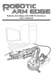
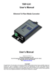
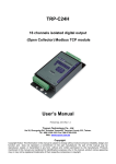
TRP-C34X 32 Bit Ethernet to 1 RS232 and 1 RS422/485 Optical Isolated Converter User’s Manual Printed OCT.2013 Ver: 1.2 Trycom Technology Co., Ltd Tel: 886-3-3503351, Fax: 886-3-3503352 Web: www.trycom.com.tw Copyright Copyright Notice: The information in this manual is subject to change without notice to improve reliability, design and function and does not represent a commitment on the part manufacturer. No part of this manual may be reproduced, copied, or transmitted in any form, without prior written permission by the manufacturer. Products mentioned in this manual are mentioned for identification purposes only. In this manual, product names appearing may or may not be registered trademarks of their respective companies or copyright. 1. Introduction TRP-C34X RS232/422/485 Serial Server provides a transparent way of connecting Serial devices over Ethernet. It can transmit data between the Serial and Ethernet interfaces bi-directionally. To establish automatic or remote data acquisition, TRP-C34X Serial Server also provides 3KV optical isolation and surge protection to protect system from ground loops and destructive. By specifying the IP address and the TCP Port number, a host computer can access different Serial Devices such as Serial Thermometers, Magnetic CNC Controller, Elevator, Data Acquisition Systems, POS Terminals, Industrial PCs etc., over the Network, you can centralize Serial Device management and distribute the management to different hosts at the same time. TRP-C34X makes possible to access distant Serial Devices over Network as if they were directly connected to the Standard COM Port of a Personal Computer. TRP-C34X supports different modes of operation allowing user to operate the system in different environments. Real COM Mode. TRP-C34X comes equipped with COM drivers that work with Operating Systems WIN 32bit XP /Vista/2003Server/2008 Server (32-bit & 64-bit), 2000 Server OS, Win 7 (32-bit & 64-bit), The driver establishes a transparent connection between host and serial device by mapping the IP: Port Number of the TRP-C34X’s Serial Port to a local COM Port on the host computer. The important point is that Real COM Mode allows users to continue using RS-232/422/485 serial communications software like HyperTerminal and similar applications. TCP Server Mode. In TCP Server mode, TRP-C34X provides a unique IP: Port address on a TCP/IP network. TRP-C34X waits passively to be contacted by the host computer, allowing the host computer to establish a connection with and get data from the serial device. This operating mode supports up to 4 simultaneous connections, so that multiple hosts can collect data from the same serial device—at the same time. TCP Client Mode. In TCP Client mode, TRP-C34X can actively establish a TCP connection to a pre-defined host computer when serial data arrives. After the data has been transferred, TRP-C34X can automatically disconnect from the host computer by using the TCP alive check time or Inactivity time settings. This Operating Mode supports establishing the TCP connection up to 4 Destination Hosts. UDP Mode. Compared to TCP communication, UDP is faster and more efficient. In UDP mode, you can multi-cast data from the serial device to multiple host computers, and the serial device can also receive data from multiple host computers, making this mode ideal for message display applications. When TRP-C34X working at unstable voltage industrial environment, the hardware circuit detection can prevent the power fail cause of the boot fail and Re-Boot. 1-1. Features Wide input range DC power supply. RS232/422/485 Built-in 3KV Optical-Isolation. Surge protection and over current and over voltage on RS-422/485 data lines. Supports Socket operation modes like TCP Server, TCP Client, and UDP using TCP/IP and UDP protocols. Support Auto-MDIX twisted pair crossover detection and auto-correction. Each Port maximum connection 4 host PC at TCP Server and TCP Client Mode. Maximum allowed bandwidth is 460 Kbps per Serial Port. Supports Web Console, Telnet Console. Runs in Stand Alone Mode. Built in Restore Factory default push button. Features Accessible Imps List to add or remove “legal” remote host IP Addresses to prevent unauthorized access to TRP-C34X. Features Auto IP Address Report to periodically report the IP Address of TRP-C34X to the assigned Host on Network. Auto direction RS485 flow control by hardware. Virtual COM drivers for WIN 32bit XP /Vista/2003Server/2008 Server (32-bit & 64-bit), 2000 Server OS, Win 7 (32-bit & 64-bit). Fully compatible with Ethernet and TCP/IP protocol. Power/Link and 2 pair Serial RX/TX mode LED indicator. Support screw terminal and standard external DC power adapter. Din rail or panel mounts support. 1-2. Features. Specification. CPU:32 bit 170MHZ with MMU. SDRAM:32MB. FLASH:8MB. Power Input Voltage: DC +10V to +30V. LAN: Auto-MDIX, 10/100 Mbps Auto-detecting. RS-232: TXD, RXD, RTS, CTS, ISO GND. RS-422: TX+, TX-, RX+, RX-, ISO GND. RS-485: Data +, Data –, ISO GND. Data Rate: 75~921Kbps. Parity: none, even, odd. Data Bits: 5, 6, 7 or 8. Stop Bits: 1, 1.5 or 2. Configuration through Windows Admin Utility / Web Console / Telnet Console. Supports Real COM mode using RFC 2217 protocol. Protocol: ICMP, TCP/IP, UDP, DHCP, Boot, Telnet, DNS, SNMP, HTTP, SMTP, SNTP. Power supply: Screw terminal, or standard external DC adapter. Serial interface: +/-15 KV ESD. RS422/485 interface: Surge, over current, over voltage protection. Power consumption: 12V/230 mA (without external device). Operating Temperature: 0 to 65 °C. Humidity: 0~90% Non-Condensing. Dimensions: 141(L)*78(W)*26.5(H) /mm. Weight: 450g (W/Packing). Hardware Description. 2-1. Block Diagram. 2-2. Panel layout and Dimension. mm/Unit. Notice: User can only choose either external DC-Jack or Screw terminal DC input. Do not use DC-Jack and screw terminal DC input simultaneously. 2-2. LED indicators. PWR LED: Blinking: Not Ready. ON: TRP-C34X Ready . LINK LED: Ethernet cable connection and data active. TX/RX LED: COMA: RS422/485 Transiting/Receiving Indicator. COMB: RS232 Transiting/Receiving Indicator. DC Jack: Power Input DC +10V to +30V. (Pleas use the 5.5*2.1mm DC JACK). 2-3. Factory default. * Push the factory restore button till the PWR LED off and then reboot. Hardware Setting: COMA: Auto Switching RS422/485. COMB: RS232. Unlock Password: trycom. Model Name: TRP-C34H-2S. Basic configuration: IP setting: Port Setting: COMA,COMB:115200,8,N,1. Operating Mode: Real Com Mode. Accessible IPs: None Setting. Auto Warning: None Setting. IP Address Report: None Setting. Password: Factory: trycom 2-4. Push Button. If lost the password or wrong setting, user can keep push button till the PWR LED off and then reboot back factory setting. 3. Installing TRP-C34X Hardware. STEP1: Connect the power source from DC-Jack or screw terminal, the PWR LED will blinking, wait till PWR LED ON. STEP2: Connect TRP-C34X with Ethernet port by RJ45 cable. If the cable is properly connected the “LINK” LED will light up. *The TRP-C34X Supports Auto-MDIX, A straight-through or crossover RJ45 cable can be used to make a connection directly to the HUB/Router/PC LAN port. STEP3: Connect TRP-C34X to RS232 by AWG #12~30 wires. Connect TRP-C34X to RS422/485 by AWG #12~30 twisted wires. 3-1.RS485 Wiring. The RS-485 mode supports the Transmit and Receive channels use twisted pair wire half-duplex operation. 3-2.RS422 Wiring. The RS-422 mode supports 4 channels with full duplex operation use dual twisted pair wire half-duplex operation. . 3-3. RS232 Wiring. Refer to the Pin out table for connections. 4. How to configure TRP-C34X. There are 3 ways to access the TRP-C34X. a. Serial Server Admin Utility. b. WEB Server. c. Telnet. 4-1. Installing Serial Server Admin Utility. The “Serial Server Admin Utility” Support WIN XP/VISTA/2003 Server/2008 Server 32/64 bit, 2000 Server/Win 7. Insert the TRP-Serial CD, find the TRP-C34X‘s folder” Utility” and run “PortSetup.exe” When Installation is completed the wizard creates a Serial Server Admin Utility shortcut on the Desktop as shown below. Double Click on the Serial Server Admin Utility then Right click on the main window or go to Server Manager in Menu Bar and select Search Devices to find the TRP-C34X on the network. By default all the devices searched are locked and can be seen under the status column of the Server Manager Window in order to protect from unauthorized configuration changes. In order to configure the device, it has to be Unlocked first. Unlock password: trycom After the device has been Unlocked, the device can be configured for all Network, Serial, Operating settings. Select the device to be configured, Right Click on the selected device and click on configure to go to Configuration menu. (Double clicking on selected device can also open the Configuration menu). This invokes the Server Manager Configuration Dialog as shown below. On Basic page, check the Modify check Box to change any of the Configuration details. IP Setting: On IP Settings Page, click the modify box first, you can modify all the Network parameter a. IP address b. Net Mask c. Gateway d. Click the IP Configuration drop-down box, to modify the parameter Static/DHCP/BOOTP. e. DNS Server 1: When the user wants to visit a particular website, the computer asks the Domain Name System (DNS) Server for the website’s correct IP address, and the computer uses the response given by DNS Server to connect to the Web Server. DNS is the way that Internet Domain Names are identified and translated into IP address. f. DNS server 2: An optional alternative of DNS Server. g. Community Name: A community name is a plain-text password mechanism that is used to weekly authenticate queries to agents of managed network devices. h. Contact: The SNMP contact information usually includes an emergency contact name and telephone or pager or Mobile number. i. Location: This string is usually set to the street address where the TRP-C34X is physically located. Port Settings Page On the Port Settings page of the Server Manager dialog displays all the serial ports, present on the Serial Server model of the selected device. It also shows the corresponding serial settings in the settings column of the page In order to see the current settings of any Serial port, select the port number in above window & then click on View settings. To modify the serial settings check the modify box on the serial page. Then “View settings” tab would be converted into “Settings” tab as below: Select any Serial Port and click on the Settings tab which will show serial settings dialog where all parameters can be viewed in enabled state. Click the checkbox “Apply Port Alias to all selected ports” to apply same port alias to all selected ports. Maximum length of Port alias is 5 characters. Click the specific drop-down box or click the check box to modify the serial port settings viz., Baud Rate / Parity / Data Bits / Stop Bits / Flow control / Interface. If Serial applications like Hyper Terminal opens a COM Port with any of above port Numbers in a Virtual PC ….. then the serial settings of that particular port change as per the Hyper terminal session opened. Operating mode Click on Operating mode which opens the operating mode page as shown Select any port and click on “View Settings” tab which shows the “Operating Mode” dialog Box as shown below. The default operating Mode is “Real Com” Mode. Note. TRP-C34X will restart automatically, after configuring the Operating Settings page. For all other pages, TRP-C34X will not restart. If modify check box is checked to activate the parameter, double click or highlight and click “Settings” tab of the specific port to modify the operating mode. Click the Operating Mode drop-down box to set the Real Com Mode / TCP Server Mode /TCP Client Mode / UDP Mode as shown below. Real COM Mode Key in the TCP Alive Check Timeout to set the timeout for TCP Alive time. The Default setting is 7 min. TRP-C34X automatically closes TCP connection if there is no TCP activity for the given time. After the connection is closed, TRP-C34X starts listening for another REAL COM driver’s connection form another host. TCP Server Mode a. Local TCP Port: The TCP Port of TRP-C34X that uses to listen to the requests coming from Host Computers on Network in order to establish connection. The Host Computers should contact this Port in order to establish connection with the TRP-C34X. b. Click the Max Connection drop-down box to set Max connection options to 1 / 2 / 3 / 4. c. TCP Alive Check Timeout (Default setting is 7 min). d. Inactivity Timeout (Default setting is 0 ==> Disabled). TCP Client Mode a. Click the Connect Mode drop-down box to set “Startup”/ “Any character”. b. Setting Destination IP address 1 and Port Number, allows TRP-C34X to connect actively to the remote host whose address is set by this parameter. c. Similarly Destination IP addresses 2 / 3 / 4, allows TRP-C34X to connect actively to the remote hosts whose address is set by this parameter. d. TCP Alive Check Timeout (Default setting is 7 min) e. Inactivity Timeout (Default setting is 0 ==> Disabled). UDP Mode a. Local Listen port: The UDP port that uses to listen to Data from multiple host computers and also to multicast data to multiple host computers. b. UDP Mode Setting Destination: c. Destination IP address 1 / 2 / 3 / 4 Accessible IP’s Page Accessible IP settings allow you to add or remove “legal” remote host IP address to prevent unauthorized access to TRP-C34X. Hosts that are included in this list can only access the TRP-C34X on the network. On “Accessible IP’s” page , click the modify box to activate the parameter, Click on settings button to enter the IP Address and Net Mask of remote host that control the TRP-C34X . You can allow one of the following cases by setting the parameter. Only one host of specific IP address can access the TRP-C34X. Enter “IP address/255.255.255.255” (e.g., “192.168.2.246/255.255.255.255”). Hosts on the specific subnet can access the address/255.255.255.0” (e.g., “192.168.2.0/255.255.255.0”). TRP-C34X. Enter “IP Any host can access the TRP-C34X. Disable this function by unchecking the “Enable” Check Box. Refer the following table for more details about the configuration example. Allowable Hosts Input format Any host Disable 192.168.2.246 192.168.2.246 / 255.255.255.255 192.168.2.1 to 192.168.2.254 192.168.2.0 / 255.255.255.0 192.168.0.1 to 192.168.255.254 192.168.0.0 / 255.255.0.0 192.168.2.1 to 192.168.2.128 192.168.2.0 / 255.255.255.128 192.168.2.129 to 192.168.2.254 192.168.2.128 / 255.255.255.128 Auto Warning Page Auto warning mechanism is a useful mechanism which sends the status messages to E-Mail id’s and Trap Servers in order to warn or acknowledge the changes made to the TRP-C34X . On Auto warning page under E-mail and SNMP Trap Setting Tab, click the modify box to activate the parameter. a. On Mail server frame, input the IP Address or Domain Name of the Mail server. b. Input the From E-mail Address. c. Enter the email addresses in the To E-Mail address boxes (1, 2, 3, 4) to whom the acknowledgement has to be sent. d. If the Mail Server has to be authenticated, check the Modify box and check the “Mail Server authentication check box”, and then press Setup button e. Input the User Name and Password to modify the Mail Server Authentication Setup. f. To set or modify the Trap Server , check the Modify checkbox and enter the IP Address or Domain name of the Trap Server to which the Auto warning are to be sent. On Auto warning page, under Event Tab, click the Modify box to activate the parameter, and click the checkbox to set the Events for which Auto warnings are to be sent. To get Auto Warning E-Mails: i) Give the Mail Server IP address & authentication if required. ii) Give from ID & To ID iii) Select on what event you want to be notified by mail in "Eventtype" page. To get Auto Warning Trap Messages, i) Key in the IP address of the Linux Machine Trap server option. ii) In Network settings page enable SNMP and provide community name, contact, and location information. iii) Run this command on Linux PC "snmptrapd -f -Le". iv) Select the event type which you want to be notified. v) On that event notice that some messages will get printed on the console where you are executing the above snmptrapd command. IP Address Report Page Network management becomes difficult when TRP-C34X is forced into DHCP. Any IP changes due to DHCP in TRP-C34X are reported to the assigned Host on the Network. On IP address Report, click the modify box to activate the parameter, and set the IP address, Port number and time period to Auto report to host. The default Port number is 4002 and the default Auto Report Period is 10 s. Password Password can be set / modified & Disabled through this screen. Maximum length of 7 characters can be supported for TRP-C34X password. Alpha, Numeric & Alpha numeric type of passwords are supported. Space is not allowed between any characters in password. 4-2. using the WEB Server mode. TRP-C34X support web console for remote configuration of the TRP-C34X on the network To view the web console, open any web browser (eg., Internet Explorer) and type the IP address in the address bar of the browser. A login form prompting for password appears. Login to the web console by entering the correct password and click submit. Default Password is “trycom”. 4-3. Telnet. TRP-C34X implements a Telnet Server and can be invoked by making a Telnet from remote PC. In the “Basic Settings” page of “Windows Configuration Utility”, if the ‘Enable Telnet Console’ check box is enabled we can use the Telnet Console to modify the device parameters. Go to Start Menu > Run Run Telnet from remote pc with the IP address of TRP-C34X as shown below: 5. Application. 5-1. Real COM Mode. TRP-C34X Basic 2 Real COM Port installs. Example: Step1: Connect PC-----RJ45-----TRP-C34X-----RS232/422/485 Device. Step2: Run “Serial Server Admin Utility” and Right Click on the selected device and click on configure to go to Configuration menu. Step3: Be sure “IP Setting”,” Port Setting” and “Operating Mode“ is correct. Step4: Select “Port Mapping” then right clicks “Add Device”. Step5: The Port Mapping will show below. Step7: Right Click select “Apply Change”. Step7: The TRP-C34X Real COM Mode setting OK. *Notice: No matter how to change “Add device” or “Remove Device”, its need to be run “Apply change” for save COM Port configuration. Step8: plug in RS232 LOOP back connector. *How to Test TRP-C34X. Trycom Technology Co.,Ltd offers test utility, this is utilities may help user to demo and test TRP-C06 fast and easily. User may find the utilities in Trycom support CD or download from Trycom web www.trycom.com.tw , direct to perform TRPCOM.exe from the directory. STEP9: Run the “TRPCOM.EXE” utility. STEP10: Click the “Setting” to set the com port and baud rate then press OK . *Please note: “COM2” is an example of COM port number; the real COM number is assigned by user PC. STEP11:. Click the "Terminal" then select Loop back enable, the counter value and pass value will be synchronized counts. Step 12. User also test RS422 loop back, Please same above step. *Demo setting “RTS/CTS” item need to Disable for test RS422. 5-2. TCP Server Mode. Example: Step1: Connect Host PC 1~8-----Ethernet-----TRP-C34X-----PC . Step2: Run “Serial Server Admin Utility” and Right Click on the selected device and click on configure to go to Configuration menu. Step3: Be sure “IP Setting”,” Port Setting” and “Operating Mode” is correct. Step4: Select “Server Monitor” then right clicks “Add Device”. Step5. Select “Go”. Step5. Connect PC COM Port link TRP-C34X COMA~COMB. Step6. RUN “Demo.exe” and select correct baud-rate and data format. Step7. RUN “Telnet.exe” and input IP and Port. 5-3. Paired Mode. Example: Step1: Run “Serial Server Admin Utility” and Right Click on the selected device and click on configure to go to Configuration menu. Step3: Be sure “IP Setting”,” Port Setting” and “Operating Mode” is correct. Step4: TRP-C34X Client setting, Select “Operating Mode” and then double click Port1~Port2 item same below. a. Port 1 Setting. b. Port 2 Setting. Step5: TRP-C34X Server setting, Select “Operating Mode” and then double click Port1~Port2 item same below. a. Port 1 Setting. b. Port 2 Setting. Step6: Keep the TRP-C34X Server in LAN. Also keep the Client PC in LAN. Step7: Power ON the TRP-C34X Server and wait till it completely boots PWR LED ON first. Step8: Power ON the TRP-C34X Client and wait till it completely boots PWR LED ON. Step9: Connect PC COM Port link TRP-C34X Client COMA~COMB by Cable. Step10: Plug in TRP-C34X server COMA~COMB by loop back connector. Step11: Run the “TRPCOM.EXE” utility. Step12: Click the “Setting” to set the com port and baud rate then press OK . *Please note: “COM2” is an example of COM port number; the real COM number is assigned by user PC. STEP11:. Click the "Terminal" then select Loop back enable, the counter value and pass value will be synchronized counts. 6. TRP-C34X Application Diagram.