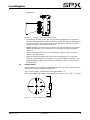
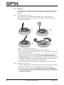
1
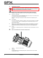
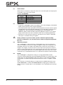
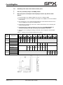
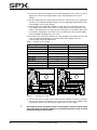
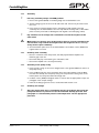
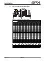
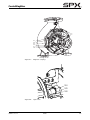
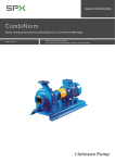
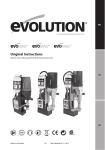
CombiMagBloc
See figure 2.
4035_A
Figure 2:
Excentric reducer to suction flange.
• The maximum allowable system pressure is stated in paragraph 10.1 "Permissible
pressure and temperature". If there is a risk that this pressure might be exceeded, for
instance because of an excessive inlet pressure, appropriate measures should be
taken by mounting a safety valve in the piping.
• Sudden changes in the rate of flow can lead to high pressure impulses in the pump
and the piping (water shock). Therefore, do not use quick-acting closing devices,
valves etc.
• Before installing the pump, first flush the piping thoroughly to clean out any dirt,
grease or possible particles.
• When mounting, place temporarily (for the first 24 operating hours) a fine gauze
between suction flange and suction pipe so as to prevent internal pump parts from
being damaged by foreign matter. If the risk of damage continues to exist, mount a
permanent filter.
3.6
PT100 element
In case the pump is provided with a PT100 element, the connections to the connection
head must be made by an approved electrician.
The connection head is provided with a cable gland M20 x 1.5.
See the following wiring diagram for the appropriate connections (rt = red, ws = white).
ws
rt
rt
Figure 3:
CMB/EN (1301) 3.4
Connecting PT 100 element
Installation
19