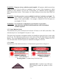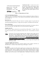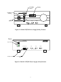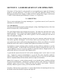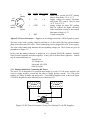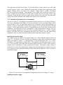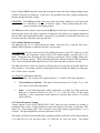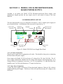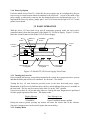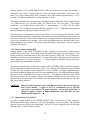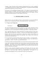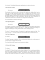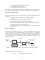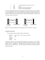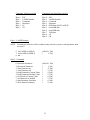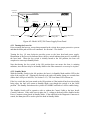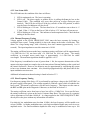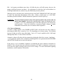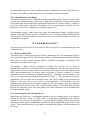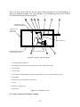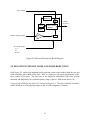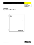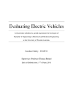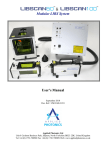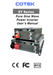
1
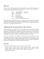
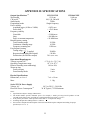
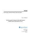
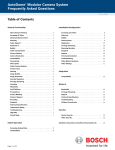
V(Black)
+5V
(Red)
+5TEC
(White)
2
3
1
4
Pin# Symbol Max Current
1
V4A
2
+5V
1A
3
+5TEC
5A
4
RET
RET
(Green)
Function
Diode laser current and TEC heating.
May be from about -3 V to -5.5 V
Supply voltage for control electronics
and crystal TEC control. May be from
+4.75 V to +5.25 V.
Supply voltage for diode TEC cooling.
May be reduced for higher efficiency
where maximum cooling is not needed.
Maximum voltage is 5.5V.
Current return path.
Figure 2-1: Power Connector - Ripples on all voltages must be < 100 mV peak-to-peak.
The laser comes with a mating connector attached to a 6-foot cable with four separate banana
plugs at the other end of the cable. These banana plugs can be plugged into a DC power supply.
The color of the banana plug indicates the corresponding voltage pin. These colors are given in
parentheses in Figure 2-1.
In the event the mating connector is misplaced, it is a Neutrik NC4FX-B connector, available
from Newark Electronics and other suppliers. It may also be ordered from Lightwave. Neutrik
may be contacted directly at:
Neutrik USA
195 Lehigh Ave.
Lakewood, NJ 08701
(908) 901-9488
2.3.1 Simplest Method for Connecting DC Power
The Series 125 is designed to be powered most simply by a pair of 5 Volt power supplies, one
wired to supply negative current and the other to supply positive current. Five volt power
supplies are widely available and inexpensive. Two identical supplies wired as shown in Figure
2-2 will be adequate for most laboratory uses of the Series 125.
5 Volts
+
5 Volts
-
+5V
+
-
V-
+5TEC
RET
Figure 2-2: DC Power Connection Using Two Identical 5 volt DC Supplies
11