1
International English
2. INSTALLATION
Operation with long cables
!
Caution
The control, power supply and motor leads must be laid separately. Do not feed them
through the same cable conduit/trunking. Never use high voltage insulation test
equipment on cables connected to the inverter.
All inverters will operate at full specification with cable lengths up to 50 m screened or
100 m unscreened.
2.4.2
Power and motor connections
!
Warning
♦
♦
♦
!
Isolate the mains electrical supply before making or changing connections to the
unit.
Ensure that the motor is configured for the correct supply voltage: single / threephase 230 V MICROMASTERS must not be connected to a 400 V three-phase
supply.
When synchronous motors are connected or when coupling several motors in
parallel, the inverter must be operated with voltage/frequency control characteristic
(P1300 = 0, 2 or 3).
Caution
After connecting the power and motor cables to the proper terminals, make sure that the
covers have been replaced properly before supplying power to the unit!
Note
♦
♦
♦
Ensure that the appropriate circuit-breakers/fuses with the specified current rating
are connected between the power supply and inverter (see table on page 102).
o
Use Class 1 60/75 C copper wire only (for UL compliance). For tightening torque
see table on page 101.
To tighten up the power terminal screws use a 4 - 5 mm cross-tip screwdriver.
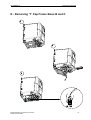
Access to the power and motor terminals
The procedure for accessing the power and motor terminals on the MICROMASTER 420
Inverter is illustrated in Appendices B and C. Please also refer to the photographs
showing the Power Terminal connections and the Control Terminal connections on the
inside of the back cover of this manual.
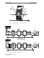
When the covers have been removed to reveal the terminals, connect the power and
motor connections as shown on the next page.
22
MICROMASTER 420 Operating Instructions
6SE6400-5AA00-0BP0