1
Jupiter Instruments_____________________________________________________________________________________
4.1.2.1 Clock Generator
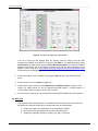
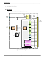
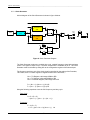
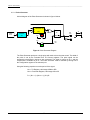
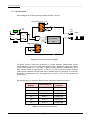
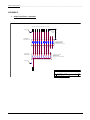
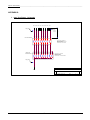
A block diagram of the Clock Generator is shown in figure 8 below.
EN
CLK
TH Counter
RCO
Set
16-bit
10 MHz
Clock
Q
TH
FF
Prescalar
8-bit
Port
Pins
Reset Q
EN
CLK
TL Counter
1
RCO
0
TL
16-bit
Vcc
Start
Set
Q
FF
Vcc
Reset Q
Stop
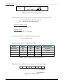
Figure 8. Clock Generator Diagram
The Clock Generator produces a variable duty-cycle, variable frequency signal with stop/start
control. The signal is output on pin 1 and the complement is available on pin 0. The Clock
Generator mode is selected by writing 20h to the configuration register of the selected port.
The frequency and duty-cycle of the clock signal is controlled by the setting of the Prescalar,
TH Counter, and TL Counter registers. Register definitions are as follows,
NTH = TH Register, valid range 0000h to ffffh
NTL = TL Register, valid range 0000h to ffffh
NPRE = Prescalar Register, valid range 00h to ffh
tH = (NTH + 1) *(NPRE + 1)*(0.1)uS
tL = (NTL + 1) *(NPRE + 1)*(0.1)uS
Using the following equations to set the CLK frequency and duty cycle
Duty Cycle
D = tH / (tH + tL)
= (NTH + 1) / ( (NTH + 1) + (NTL + 1) )
Frequency
f = 1/ (tH + tL )
7
= 10 / ( (NTH + NTL + 2)( NPRE + 1 ) ) Hz
JI-4040
21
4/25/11