1
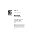
Neptune OBS
Operation Guide.
Part No. MAN-OBS-0002
Designed and manufactured by
Güralp Systems Limited
3 Midas House, Calleva Park
Aldermaston RG7 8EA
England
Proprietary Notice: The information in this manual is
proprietary to Güralp Systems Limited and may not be
copied or distributed outside the approved recipient's
organisation without the approval of Güralp Systems
Limited. Güralp Systems Limited shall not be liable for
technical or editorial errors or omissions made herein,
nor for incidental or consequential damages resulting
from the furnishing, performance, or usage of this
material.
Issue A
2009-08-21
MAN-OBS-0002
Table of Contents
1
2
Introduction......................................................................................................................................3
Operation Guide..............................................................................................................................4
Principals of operation................................................................................................................4
Power monitoring and control....................................................................................................4
2.2.1
Operation.....................................................................................................................4
2.2.2
Configuration...............................................................................................................8
2.3 Deployment...............................................................................................................................10
2.4 Recovery....................................................................................................................................17
2.1
2.2
3
3.1
3.2
Appendices.....................................................................................................................................20
Main Connector pin-out............................................................................................................20
Test harness pin-outs................................................................................................................22
3.2.1
Overview....................................................................................................................22
3.2.2
Aquadopp test connector..........................................................................................23
3.2.3
Differential Pressure Gauge test connector.............................................................24
3.2.4
Battery test connectors..............................................................................................25
3.2.5
Power Supply test connectors...................................................................................25
3.2.6
RS232 Data Out test connector.................................................................................26
3.2.7
Ethernet test connector.............................................................................................27
4
Revision history.............................................................................................................................28
2
Issue A
Operation guide
1 Introduction
Güralp Systems' “Neptune” Ocean Bottom System is a state-of-the-art
multi-sensor unit comprising:
•
a CMG-5T triaxial true broadband feedback strong motion
(±2g) accelerometer;
•
a CMG-1T triaxial true broadband (360s - 50Hz) feedback
seismometer;
•
a CMG-DM24/7 24-bit, seven channel digitiser module;
•
a CMG-EAM enhanced acquisition and communications
module; and
•
GSL's unique “Virtual Sphere” microprocessor-controlled
orientation and levelling system
all encased in a cast titanium sphere capable of withstanding
immersion in up to 3,000 metres of water.
A submersible 25-pin connector provides inputs for an external Nortek
Aquadopp triaxial Doppler-effect current flow rate meter, an external
differential pressure gauge, main 48V
power and an auxiliary 12V back-up
battery as well as data outputs via
RS232 and TCP/IP Ethernet.
The integrated CMG-EAM provides a
single,
easy-to-use,
web-based
interface for control, configuration
and monitoring of all components.
Sophisticated
power-control
electronics
provide
fine-grained
monitoring and control of power
consumption, minimising current
requirements
and
maximising
battery life.
The CMG Neptune OBS embodies
more
than
twenty
years
of
experience in designing and deploying ocean-bottom seismometry
systems in some of the harshest and most challenging environments
on the planet.
August 2009
3
MAN-OBS-0002
2 Operation Guide
2.1 Principals of operation
The CMG Neptune OBS contains two seismometers, a CMG-5T strong
motion triaxial accelerometer and a CMG-1T weak motion triaxial
seismometer.
Full details and specifications of the CMG-5T components are
contained in Güralp manual MAN-050-0001, available for download
from http://www.guralp.com/documents/MAN-050-0001.pdf.
Full details and specifications of the CMG-1T components are
contained in Güralp manual CMG-1OBS, available for download from
http://www.guralp.com/support/manuals/pdf/1OBS.pdf.
The outputs from these two systems, along with the output of the
differential pressure gauge, are connected internally to a CMG-DM24/7
digitiser module. Full details and specifications for this module are
contained in Güralp manual MAN-D24-0004, available for download
from http://www.guralp.com/documents/MAN-D24-0004.pdf.
The outputs from the CMG-DM24/7 and the Aquadopp flow meter are
connected internally to an embedded CMG-EAM acquisition and
communication module. Full details for this module are contained in
Güralp manual MAN-EAM-0001, available for download from
http://www.guralp.com/documents/MAN-EAM-0001.pdf.
The EAM software has been extended to include functions specific to
the CMG Neptune OBS. These are:
•
an enhanced power monitoring and control system; and
•
deployment and recovery sequence automation.
These functions are described in the sections that follow.
2.2 Power monitoring and control
2.2.1 Operation
The CMG Neptune OBS includes a power monitoring and control
facility which can measure and switch the current flowing to and from
the various components of the system. This can be accessed via the
configuration interface of the CMG-EAM using a web browser.
4
Issue A
Operation guide
The configuration interface of the CMG-EAM is described in detail in
MAN-EAM-0001. The following description assumes some familiarity
with the use of this interface.
To access the power monitoring and control facility, select “Digital
I/O” from the Control menu:
The following screen will appear:
August 2009
5
MAN-OBS-0002
The screen is divided into sections, each dealing with a different
current switch/measurement point, known as a “line”.
Each line has a system name and a user name. User names can be
configured individually (see Section 2.2.2 on page 8). For example,
the first line displayed in the previous diagram has a system name of
“Aux_power” and a user name of “Auxiliary (battery) power”.
Next to the name of each line is displayed the line's status: low (off) or
high (on). A line can be turned on and off with the “Set output low”
and “Set output high” buttons. Note: the Neptune OBS systems are
shipped with many power lines set low (turned off) in order to avoid
unintentional battery drain. The default status of each line at powerup can be configured (see Section 2.2.2 on page 8).
Below the status is displayed the measured voltage, current and power.
The buttons marked “View details/settings” displays a screen similar to
the following. The screen for Aux_power is used for illustration:
6
Issue A
Operation guide
Most of the features of this screen duplicate those on the main “Digital
I/O” display. A “Refresh” button provides quicker access to the latest
figures if a line is being monitored in real time.
The two fields not present on the main “Digital I/O” display allow the
configuration of under-voltage monitoring. If a voltage is typed into
the “Lower voltage cut-off threshold” field and the “Set” button
pressed, the system will cut power to the associated subsystem if the
supply voltage falls below the figure entered. In order to prevent rapid
switching when the supply power is very close to the threshold, a
hysteresis value can also be entered. The supply voltage must rise to
the sum of the threshold voltage and the hysteresis voltage before
power to the associated subsystem is restored.
The allocation of lines to hardware components for the CMG Neptune
OBS is as follows:
Line (system name)
Function
Data_Out
Main 48V power feed (conditioned)
Aux_power
Auxiliary battery
Port_A
Power to embedded DM24/7
Sensor_power
Power to CMG-1T sensor
Ext0_power
Power to CMG-5T sensor
Ext1_power
Power to D.P.G.
Port_D
Power to Aquadopp
Note: both the incoming 48V power and the auxiliary battery power
are both fed through a power conditioning circuit before being routed
to the power control sensors, so it is the conditioned voltage that is
monitored, not the supplied voltage.
Note: The auxiliary battery will not be used unless the output for
Aux_power is set high, in order to conserve battery life during
shipping and deployment. The status of this line immediately after
the unit boots can be configured: see Section 2.2.2 on page 8.
August 2009
7
MAN-OBS-0002
2.2.2 Configuration
To configure the user names of the power lines, select “All options”
from the “Configuration” section of the main menu:
From the resulting menu, select “GPIO labels and power switch
settings. The following screen is displayed, from where it is possible
to edit the user labels of the :power lines. Press the “Submit” button
after making any changes.
Below the GPIO labels configuration section, a number of drop-down
menus allow you to configure the state (on or off) which each line will
assume when the unit boots when power is first applied or after a
power interruption. This part of the screen is shown overleaf.
For each line, select the desired start-up state, then click the “Submit”
button to save your changes.
Note: no immediate changes to individual lines will be made as a
result of using this feature. The settings only affect the lines after a reboot of the unit.
8
Issue A
Operation guide
Note: The auxiliary battery will not be used after the unit is rebooted
unless the power-up state for Aux_power is set to “Power On”, in order
to conserve battery life during shipping and deployment. The battery
can still be turned on and off using the appropriate controls on the “I/
O Line Status” screen, as described in Section 2.2.1 on page 4.
August 2009
9
MAN-OBS-0002
2.3 Deployment
The CMG-EAM embedded in the Neptune OBS has a facility for
automating the instrument deployment sequence, which involves
checking the position of the OBS bowl (the internal, moveable
instrument carrying platform) and, if it needs to be moved, locking the
sensor masses (if not already locked) and then entering an iterative
sequence of tilts, turns and orientation measurements until the bowl is
precisely level. The instrument masses are then individually unlocked
and centred. This whole sequence is triggered via controls within the
configuration interface of the CMG-EAM, using a web browser.
The configuration interface of the CMG-EAM is described in detail in
MAN-EAM-0001. The following description assumes some familiarity
with the use of this interface.
To initiate the deployment sequence, choose the entry for the sensor
from the “Control” menu (the name of this entry will change with the
serial number of the component).
Scroll down the resulting page to the section headed “Ocean Bottom
Systems”
The following screen is displayed:
10
Issue A
Operation guide
In normal use, only “Deploy” (described here) and “Recover”
(described in Section 2.4 on page 17) will be required. Both of these
run sequences of individual commands and it is possible to run any of
these individual commands from this screen.
The deployment sequence is:
•
Level - level the OBS bowl;
•
Align - Align the OBS bowl (to magnetic north);
•
Unlock OBS Components- unlock each sensor in turn; and
•
Centre OBS Components - centre each sensor masses in turn.
The entire sequence can be run in the correct order by clicking the
“Run” button in the “Deploy” box. This produces a large amount of
diagnostic output to signify the progress of the operation. The bowl
alignment procedure is iterative and several passes may be needed to
achieve an acceptable attitude. Typical output is reproduced here,
with explanatory notes in blue:
August 2009
11
MAN-OBS-0002
Digitiser Control
GSLA-1717
Deploy
GSLA 171700 CMG1T2M Command Mode
0 blocks in buffer | 256 blocks free
Guralp Systems Ltd - DM+FW v.106 mgs
ok_1717
DEPLOY
Deploy System? y/n
? y x-3 y-258
(the bowl is not
Z Mass Locking..
lock the masses
0 249
Success
Vertical Mass_Locked (Turned)
Mass Position -102%
N/S Mass Locking..
7 249
Success
North/South Mass_Locked (Not Turned )
Mass Position 102%
E/W Mass Locking..
10 249
Success
East/West Mass_Locked (Not Turned )
Mass Position 102%
1
1
1
1
1
1
1
1
1
1
1
1
1
1
0
0
0
0
0
0
1
1
1
1
1
1
1
1
2
1
| Tilt |Rotate|
0
0
Y450
1
1
1
1
1
1
1
0
11
48
84
120
12
aligned, so we will
before moving it)
(these numbers show the current bowl
tilt value...)
42
42
41
39
40 Limit Switch
39
40
40
40
41
41
42
17/08/09 (Build 33)
1
1
1
1
1
1
1
1 1 0 1 1 1 1 1now
1
1
1
1
1
1
1
1 1 1 0 1 0 1 1
1
1
1
1
1
1
1 TiltNull set 41
(...and these the rotation value)
X |
Y |
-3
-260 << Bowl Datum x-3
y-258
x-4
(bowl now at datum and a new target
orientation has been calculated)
(bowl tilting)
Issue A
Operation guide
154
190
224
261
295
331
365
404
440
455
453
451 x-5
y249
T62
(bowl rotating)
0
1
5
10
12
16
18
this sequence will continue changing gradually.
lines of output have been suppressed.
|
59
60
60
60
60
60
60
61
Tilt |Rotate|
61
452
X |
51
Y |
-20 x50
st
y20
Several hundred
R447
(1 approximation achieved,
2nd calculated)
451
451
449
446 x50
61
61
61
61
62
62
62
(bowl tilting)
y19
T78
(bowl rotating)
this sequence will continue changing gradually.
lines of output have been suppressed.
Several hundred
76
76
76
76
76
August 2009
13
MAN-OBS-0002
77
77
447
447
443
442
441
439
437
435
433 x50
77
77
434
433
431
430
428
426
424
422
419 x33
77
77
77
77
77
77
77
77
77
77
76
76
76
76
75
76
75
75
75
74
74
74
74
73
73
419
419
417
415
413
411 x20
14
447
y-50
433
y-53
420
y-32
63
44 x62
y-43
x62
y-43
R432
50 x49
y-50
x49
y-50
R419
35 x27
y-35
x27
y-35
R411
T77
50
T72
27
T71
Issue A
Operation guide
73
74
73
73
72
72
411
411
409
407
405 x14
411
y-28
72
72
72
72
72
71
71
405
404
404
402
400 x8
y-24
71
72
71
70
71
70
70
70
70
69
68
69
400
400
400
397 x4
y-16
19
31 x18
y-31
x19
y-31
R404
27 x12
y-26
x11
y-26
R400
T70
12
T67
6
17 x5
y-17
x5
y-18
R397
T66
69
69
69
68
68
68
68
67
67
398
2
11 x2 y-12 x2 y-11 < Bowl Level
SingleBowl System : Levelled
(success)
Z LOCKED N/S LOCKED E/W LOCKED
| Tilt |Rotate|
X |
Y |
67
398
3
11
Z Mass UnLocking..
(now unlock the masses)
54 249
August 2009
15
MAN-OBS-0002
59 248
61 247
59 246
57 245
54 244
53 243
57 242
(the first number is the current
57 241
drawn by the locking motors,
56 240
the second a simple count-down
56 239
timer)
60 238
60 237
61 236
61 235
61 234
61 233
61 232
56 231
56 230
56 229
57 228
58 227
59 226
56 225
56 224
59 223
61 222
59 221
59 220
54 219
57 218
54 217
60 216
32 215
Success
Z Mass Centring..
-85
59
Success
Vertical Mass_Unlocked Centred Turned
Mass Position -4%
N/S Mass UnLocking..
8 249
Success
N/S Mass Centring..
2047
59 1 1 1 1 1 1 1 1 128 -1
0
-1693
58 1 1 1 1 1 1 1 1
96 1
0
2047
57 1 1 1 1 1 1 1 1
72 -1
0
-1122
56 1 1 1 1 1 1 1 1
54 1
0
2047
55 1 1 1 1 1 1 1 1
40 -1
0
342
54 1 1 1 1 1 1 1 1
40 -2
0
-1582
53 1 1 1 1 1 1 1 1
30 1
0
-823
52 1 1 1 1 1 1 1 1
30 2
0
2047
51 1 1 1 1 1 1 1 1
22 -1
0
2047
50 1 1 1 1 1 1 1 1
22 -2
0
-4
49
Success
North/South Mass_Unlocked Centred Not Turned
Mass Position
0%
16
Issue A
Operation guide
E/W Mass UnLocking..
10 249
Success
E/W Mass Centring..
-772
59 1 1 1 1 1 1 1 1 128 1
0
2047
58 1 1 1 1 1 1 1 1
96 -1
0
-254
57 1 1 1 1 1 1 1 1
72 1
0
1379
56 1 1 1 1 1 1 1 1
54 -1
0
85
55
Success
East/West Mass_Unlocked Centred Not Turned
Mass Position
4% ok_1717
Command 'Deploy' run successfully
Generated at 2009-08-18T11:19:11Z by digitiser-control.cgi 2.0.2 .
Portions of output copyright (c)2009, Guralp Systems Ltd..
2.4 Recovery
The CMG-EAM embedded in the Neptune OBS has a facility for
automating the instrument pre-recovery sequence, which involves
locking the instrument masses prior to any potentially violent
movements. This is accessed via the configuration interface of the
CMG-EAM using a web browser.
The configuration interface of the CMG-EAM is described in detail in
MAN-EAM-0001. The following description assumes some familiarity
with the use of this interface.
To initiate the deployment sequence, choose the entry for the sensor
from the “Control” menu (the name of this entry will change with the
serial number of the component).
August 2009
17
MAN-OBS-0002
Scroll down the resulting page to the section headed “Ocean Bottom
Systems”
The following screen is displayed:
In normal use, only “Deploy” (described in section 2.3 on page 10) and
“Recover” (described here) will be required. Both of these run
sequences of individual commands and it is possible to run any of
these individual commands from this screen.
The recovery sequence is:
•
Lock OBS Components- lock each sensor in turn; and
•
Return to Datum - return the bowl leveller to the “home”
position
The entire sequence can be run in the correct order by clicking the
“Run” button in the “Recover” box. This produces diagnostic output to
signify the progress of the operation. Typical output is reproduced
here, with explanatory notes.
18
Issue A
Operation guide
Digitiser Control
GSLA-1717
Recover
GSLA 171700 CMG1T2MCommand Mode
1 blocks in buffer | 255 blocks free
Guralp Systems Ltd - DM+FW v.106 mgs
17/08/09 (Build 33)
ok_1717
RECOVER
Lock sensors for recovery? y/n
? y
Z Mass Locking..
86 249
Success
Vertical Mass_Locked Turned
Mass Position -102%
N/S Mass Locking..
82 249
Success
North/South Mass_Locked Not Turned
Mass Position 102%
E/W Mass Locking..
86 249
Success
East/West Mass_Locked Not Turned
Mass Position 102%
41
41
41
40
39
39 Limit Switch
39
39
40
40
41
41
41
|
1
1
1
1
1
1
1
1
1
1
1
1
1
1
0
0
0
0
0
0
1
1
1
1
1
1
1
1
1
Tilt |Rotate|
-1
1
1
1
1
1
1
1
1
1
1
1
1
1
1
1
1 1 0 1 1 1 1 1now
1
1
1
1
1
1
1
1 1 1 0 1 0 1 1
1
1
1
1
1
1
1 TiltNull set 42
X |
Y |
-3
-258 ok_1717
Command 'Recover' run successfully
Generated at 2009-08-18T11:19:11Z by digitiser-control.cgi 2.0.2 .
Portions of output copyright (c)2009, Guralp Systems Ltd.
August 2009
19
MAN-OBS-0002
3 Appendices
3.1 Main Connector pin-out
This is a SEACON MIN-M-25-FSS 25-pin
male connector.
A suitable mating connector is provided.
Additional connectors are available from
Güralp Systems Ltd. or from Seacon directly
at http://www.seaconbrantner.com/.
The pin use is illustrated below and tabulated overleaf:
20
Issue A
Operation guide
Pin Function
1
EAM data ground
2
Aquadopp positive supply V+
3
Aquadopp supply ground
4
Aquadopp power cable braid (shield)
5
DPG positive reference voltage +Vref
6
Aquadopp receive data
7
Aquadopp transmit data
8
Aquadopp data cable braid (shield)
9
DPG negative reference voltage -Vref
10
DPG +
11
EAM DATA OUT transmit data
12
EAM DATA OUT receive data
13
main power supply cable braid (shield)
14
battery supply cable braid (shield)
15
DPG reference voltage cable braid (shield)
16
DPG -
17
Ethernet Rx-
18
Ethernet Tx-
19
main power supply -ve
20
battery -ve
21
DPG signal? cable braid (shield)
22
Ethernet Rx+
23
Ethernet Tx+
24
Main power supply +ve
25
battery +ve
Wiring details for the compatible socket, as
seen from the cable end.
August 2009
21
MAN-OBS-0002
3.2 Test harness pin-outs
3.2.1 Overview
The test harness is shown below. Pin numbers in italics refer to the
pins in the Seacon connector, as documented in Section 3.1 on page
20. The individual connectors are described in the following sections.
22
Issue A
Operation guide
3.2.2 Aquadopp test connector
These are standard DE9M (TIA-574)
sub-miniature (D-sub) plugs, conforming to
DIN 41652 and MIL-DTL-24308. They are
very widely available, as are suitable mating
connectors.
Pin Function
Associated Seacon pin
1
not connected
2
RS232 transmitted data*
7
3
RS232 received data*
6
4
not connected
5
Ground
6
not connected
7
not connected
8
Supply voltage +ve
9
not connected
2
4
*Note: The Aquadopp is considered the DTE and the Neptune OBS the
DCE for this connection, so “transmitted” refers to data from the
Aquadopp and “received” to data received by the Aquadopp.
Note: the supply lines are shielded with the cable braid connected to
pin 3 of the Seacon connector.
Note: the data lines are shielded with the cable braid connected to pin
8 of the Seacon connector.
Wiring details for the compatible socket,
DE9F, as seen from the cable end.
August 2009
23
MAN-OBS-0002
3.2.3 Differential Pressure Gauge test connector
These are standard DE9F (TIA-574)
sub-miniature
(D-sub)
line
sockets,
conforming
to
DIN
41652
and
MIL-DTL-24308.
They are very widely
available, as are suitable mating connectors.
Pin Function
Associated Seacon pin
1
-DPG
16
2
- Vref
9
3
+DPG
10
4
+Vref
5
5
not connected
6
not connected
7
not connected
8
not connected
9
not connected
Note: the '+' and '-' lines are shielded with the cable braid connected to
pin 21 of the Seacon connector.
Note: the reference lines are shielded with the cable braid connected
to pin 15 of the Seacon connector.
Wiring details for the compatible plug,
DE9M, as seen from the cable end.
24
Issue A
Operation guide
3.2.4 Battery test connectors
These are standard 4mm “banana” plugs.
They are very widely available, as are
suitable mating connectors.
Cable / Plug
Function
Associated Seacon pin
Yellow / Red
+ve
25
Green / Green
-ve
20
Note: if the battery cable is shielded, the cable braid should be
connected to pin 14 of the Seacon connector.
3.2.5 Power Supply test connectors
These are standard 4mm “banana” plugs.
They are very widely available, as are
suitable mating connectors.
Cable / Plug
Function
Associated Seacon pin
Red / Red
+ve
24
Green / Green
-ve
19
Note: if the power supply cable is shielded, the cable braid should be
connected to pin 13 of the Seacon connector.
August 2009
25
MAN-OBS-0002
3.2.6 RS232 Data Out test connector
This is a standard DE9F (TIA-574)
sub-miniature
(D-sub)
line
sockets,
conforming
to
DIN
41652
and
MIL-DTL-24308.
They are very widely
available, as are suitable mating connectors.
Pin Function
Associated Seacon pin
1
not connected
2
Transmitted data*
11
3
Received data*
13
4
not connected
5
Ground
6
not connected
7
not connected
8
not connected
9
not connected
1
Wiring details for the compatible plug,
DE9M, as seen from the cable end.
Note: The embedded CMG-EAM is considered to be the DTE for this
connection, so “Transmitted” refers to data from the CMG-EAM and
“Received” refers to data received by the CMG-EAM.
26
Issue A
Operation guide
3.2.7 Ethernet test connector
This is a standard 8P8C modular line jack,
conforming to ANSI/TIA-968-A and IEC
60603. They are very widely available, as
are suitable mating connectors.
Pin Function
Associated Seacon pin
1
Rx +
22
2
Rx -
17
3
Tx +
23
4
not connected
5
not connected
6
Tx -
7
not connected
8
not connected
18
Note: the connector is wired in “MDI” mode, which is suitable for
connection to a hub, switch or router. In order to make a direct
connection to, for example, a PC's network adaptor, it may be
necessary to use a cross-over adaptor.
Note: the colour-codes of the individual cable cores conform to
TIA/EIA-568-B.
Wiring details for the compatible socket, as
seen from the back, e.g. when soldering.
August 2009
27
MAN-OBS-0002
4 Revision history
2009-08-19 A
28
New Document
Issue A