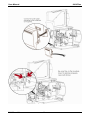
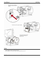
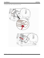
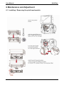
1
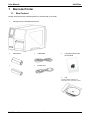
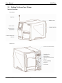
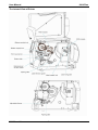
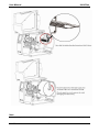
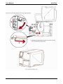
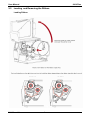
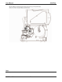
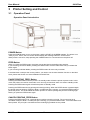
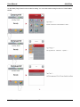
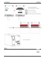
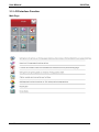
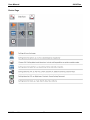
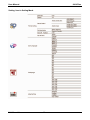
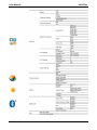
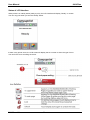
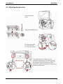
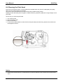
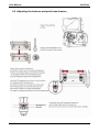
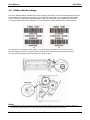
User Manual MAN10xxx-01 User Manual 6414 Plus CONTENTS Page 1 Barcode Printer 1 1.1 Box Content 1 1.2 Getting to Know Your Printer 2 2 Printer Setup 4 2.1 Loading the label roll 4 2.2 Loading and Removing the Ribbon 8 2.3 Connecting the Printer to the Host Computer 10 2.4 Installing Printer Driver directly from CD folder 11 3 Printer Setting and Control 14 3.1 Operation Panel 14 3.2 LCD Interface Introduction 15 3.3 LCD Interface Function 20 3.4 Label Calibration and Self Test 25 3.5 Error Alerts 27 3.6 USB Host 28 4 NetSetting for Ethernet 34 4.1 Installing the NetSetting Software 34 4.2 The Interface of NetSetting 35 5 Accessories 42 5.1 Preparation Steps 42 5.2 Installing the Cutter 49 6 Maintenance and Adjustment 46 6.1 Installing / Removing the print head module 46 6.2 Adjusting the print line 47 6.3 Adjusting ribbon tension 47 6.4 Cleaning the thermal print head 49 6.5 Adjusting the balance and print head tension 50 6.6 Ribbon shield settings 51 6.7 Cutter settings 52 6.8 Troubleshooting 53 Appendix 53 Product Specifications 53 Interface MAN10xxx-01 i User Manual 6414 Plus FCC COMPLIANCE STATEMENT FOR AMERICAN USERS This equipment has been tested and found to comply with the limits for a CLASS A digital device, pursuant to Part 15 of the FCC Rules. These limits are designed to provide reasonable protection against harmful interference when the equipment is operated in a commercial environment. This equipment generates, uses, and can radiate radio frequency energy and, if not installed and used in accordance with the instructions, may cause harmful interference to radio communications. Operation of this equipment in a residential area is likely to cause harmful interference in which case the user will be required to correct the interference at own expense. SERIESTO WHICH THIS DECLARATION RELATESIS CONFORMITY WITH THE FOLLOWING STANDARDS IN CFR 47, Part 15 WARNING This is a Class A product. In a domestic environment this product may cause radio interference in which case the user may be required to take adequate measures. MAN10xxx-01 ii User Manual 6414 Plus SAFETY INSTRUCTIONS Please read the following instructions carefully. 1. 2. 3. 4. Keep the equipment away from humidity. Before you connect the equipment to the power outlet, pleasecheck the voltage of the power source. Make sure the printer is off before plugging the power connector into the power jack. It is recommended that you connect the printer to a surge protector to prevent possible transient overvoltage damage. 5. Be careful not to get liquid on the equipment to avoid electrical shock. 6. For safety and warranty reasons, ONLY qualified service personnel should open the equipment. 7. Do not repair or adjust energized equipment under any circumstances. Caution Danger of explosion if battery is incorrectly replaced. Replace only with the equivalent type recommended by the manufacturer. Dispose of used batteries according to the manufacturer’s instructions. Only use with designated power supply adapter model. Changes or modifications not expressly approved by the party responsible for compliance could void the user's authority to operate the equipment. MAN10xxx-01 iii User Manual 1 6414 Plus Barcode Printer 1.1 Box Content Please check that all of the following items are included with your printer: Compuprint 6414 Plus Barcode Printer Label Stock USB Cable Ribbon Power Cord Compuprint 6414 Plus Quick Guide CD Including QLabel software and Compuprint 6414 Plus user manual MAN10xxx-01 1 User Manual 1.2 6414 Plus Getting To Know Your Printer Device Overview Front View Rear View MAN10xxx-01 2 User Manual 6414 Plus The Internal View of Printer MAN10xxx-01 3 User Manual 2 6414 Plus Printer Setup 2.1 Loading the Label Roll This printer supports the following printing methods: Thermal transfer printing (TTP): Requires a ribbon for transferring a printed image to a media. Direct Thermal printing (DTP): Does not requiresa ribbon, only thermal paper. Please check which printing method you are using and after the setting accordingly in the printer driver. Printer menu, and/or software. MAN10xxx-01 4 User Manual 6414 Plus Note * When moving the label roll guide, hold it only by the end that is attached to the bracket, not by its top. MAN10xxx-01 5 User Manual 6414 Plus Note * Remember to set the movable sensor to gap, black mark, or tag hole by changing the position of the sensor with the movable sensor. MAN10xxx-01 6 User Manual MAN10xxx-01 6414 Plus 7 User Manual 2.2 6414 Plus Loading and Removing the Ribbon Loading Ribbon MAN10xxx-01 8 User Manual 6414 Plus Note * Do not pass the ribbon under the sensor. MAN10xxx-01 9 User Manual 2.3 1. 2. 3. 4. 6414 Plus Connecting the Printer to the Host Computer Please make sure that the printer is switched off. Connect the power cord to the AC power. USB/serial cable to the printer and host computer. Switch on the printer. The operator panel should now light up. MAN10xxx-01 10 User Manual 6414 Plus Installing Printer Driver Directly from CD Folder 1. Insert the product CD in the CD/DVD drive of the host computer and open the "Seagull Drivers" folder on the CD. Select the icon for the driver file and click it to start the installation. 2. Follow the instructions on the screen. The Driver Wizard guides you through the installation procedure. Select "Install printer drivers". 3. Specify your printer model. MAN10xxx-01 11 User Manual 6414 Plus 4. Specify the port to be used to connect the printer to the host computer.. 5. Enter a printer name and assign the appropriate rights. 6. Once the installation is complete, a summary of the printer settings is displayed. Check whether the printer settings are correct and click "Finish" to start copying the driver files. Wait until copying is complete, then finish the installation. MAN10xxx-01 12 User Manual 7. 6414 Plus Once the driver installation is complete, the new printer should appear in the "Printers and Faxes" folder. MAN10xxx-01 13 User Manual 3 3.1 6414 Plus Printer Setting and Control Operation Panel Operation Panel Introduction POWER Button Press the POWER button to turn on the printer, and the START UP SCREEN appears. The printer is on “ready to print” status, the LCD screen should display the message “READY“ on the screen. When printer is turned on, keep pressing the POWER button for 3 second will turn the printer off. FEED Button When you press the FEED button, the printer moves the label to the defined stop position. If you are using continuous labels, pressing the FEED button will move label stock until you release the button again. If you are using individual labels, pressing the FEED button will move only one label. If the label does not stop at the correct position, you need to run the auto-detection function on the label stock, please see Section 3.4 Label Calibration and Self Test. PAUSE PRINTING_FEED Button Pressing the FEED button while the printer is in standby mode will set the printer to pause mode. In this mode, the printer can receive commands, but it can only process them when it is reset to standby mode. Pressing the FEED button again will reset the printer to standby mode. Pressing the FEED button during printing will interrupt printing. When the PFEED button is pressed again, the printer resumes printing. Example: While a 10-label print job is running, you press the FEED button to pause the printer. Two of the labels have been printed. To resume printing and print the remaining eight labels, you press the FEED button again. CANCEL PRINTING_FEED Button Pressing the FEED button over 3 seconds during printing cancels a print job. The current print job is cancelled. Example: While a 10-label print job is running, you press the FEED button. Two of the labels have been printed. The print job is cancelled and the remaining eight labels are not printed. MAN10xxx-01 14 User Manual 3.2 6414 Plus LCD Interface Introduction Getting Started Press the POWER button to turn on the printer, and the START UP SCREEN appears. If the printer is on “ready to print” status, the LCD screen should display the message “Ready“ on the screen. Use touch gestures to get around the Home screen and other screen for setting. MAN10xxx-01 15 User Manual 6414 Plus On the Ready Page, three function mode for setting. You can make various string functions in FUNCTIONAL MODE. MAN10xxx-01 16 User Manual MAN10xxx-01 6414 Plus 17 User Manual 6414 Plus Keyboard Mode When plug-in an USB keyboard to the printer, LCD touch panel will display “Enter Standalone”, press the “Y” key on keyboard to entering to the dialog for “Keyboard Mode” operation. Preview Label Function User can choose any label which have done in the printer and preview it. (See instructions). MAN10xxx-01 18 User Manual 6414 Plus Notice * Using recall label function send commands, printer display must be back to Ready Page. MAN10xxx-01 19 User Manual 6414 Plus 3.3 LCD Interface Function Main Page MAN10xxx-01 20 User Manual 6414 Plus Device Page MAN10xxx-01 21 User Manual 6414 Plus Setting Item in Setting Mode MAN10xxx-01 22 User Manual MAN10xxx-01 6414 Plus 23 User Manual 6414 Plus Status of LCD Interface When printer is on stanby status (ready to print), the LCD interface will display “Ready” on screen. You can only print when you see the “Ready” status. If there is any printer errors, the LCD screen will display the error screen to show the type of error. You can fix the error according the notice. MAN10xxx-01 24 User Manual 6414 Plus 3.4 Label Calibration and Self Test Label Calibration The printer can automatically detect and store label height. That means the host computer does not need to transmit the label height to the printer. Self Test Self-test function lets you check whether the printer is functioning normally. Here is how you run the label size calibration and self test. 1. 2. 3. 4. Check that the label stock is loaded correctly. Turn off the printer. Turn the printer on again, keeping the FEED button pressed. When the LED starts to flash red, release the FEED button. The printer will now measure the label stock and store the label height. Once the printer has successfully measured the label stock, it will print a self-test label. The contents of a self-test printout are listed below. MAN10xxx-01 25 User Manual 6414 Plus Label Calibration Button A hardware button to make a Label Calibration while printer encountering ‘’Media Error’’ during the cases when first-time printer start up or change label or ribbon to another type, such as change using gap label to continuous or black mark labels. Press C-button for 2 seconds, it will make an auto-sensing to calibrate the label and ribbon’s parameters. Notice ****Press C-button is equivalent to the auto-sensing command ‘’~S,SENSOR’’ that will cancel on-printing-job and make the Label Calibration immediately. . MAN10xxx-01 26 User Manual 6414 Plus 3.7 Error Alerts In the event of a problem that prevents normal functioning of the printer, you will see an error message on LCD screen and hear some beep signals. Please refer to below table for the error alerts. MAN10xxx-01 27 User Manual MAN10xxx-01 6414 Plus 28 User Manual 6414 Plus 3.8 USB Host Definition : USB Host port supports either device USB memory stick, keyboard or scanner. Purpose USB memory stick : It extends the user memory space up to 32GB for Graphic, Font, Label Format, DBF and Command files downloading. The printer’s Firmware also can be updating if copy new version of Firmware into USB memory stick. Connecting an USB keyboard to printer for ‘’ Standalone’’ mode operation. Plug-in an USB scanner to operate the printer in ‘’Standalone’’ mode. Usage of Extended Memory USB memory stick : It supports hot-plugging function; printer will create a Folder ‘’\LABELDIR’’ and switch ‘’User Flash’’ to ‘’ Extended Memory‘’ automatically while user plugs an USB memory stick into a the printer. Connect the USB Stick plugged -in printer to PC via USB Device or Ethernet port and run ‘’GoLabel CP’’ software to download Graphic, Font, Label Format, DBF and Command files to the printer. Detail download procedures, please refer to ‘’GoLabel CP On-line Help’’. Usage of Firmware Update Remove USB memory stick from printer and plug-in it to a PC’s USB port; delete Firmware ‘’*.bin’’ file from ‘’\LABELDIR\FW’’ of USB memory stick if it existing; or create a Folder ‘’\LABELDIR\FW’’ to USB memory stick if it doesn’t existing. Copy a new version of Firmware ‘’xxxx.bin’’ to the Folder ‘’\LABELDIR\FW’’; and then remove USB and plug-in back to the printer that going to update Firmware. The printer will update the Firmware automatically when plug-it-into the printer and printer find-out the Firmware in ‘’\LABELDIR\FW’’ is newer version. Don’t remove the USB memory stick out while it’s under updating with ‘’Flash Writing...’’message that displays on LCD panel. MAN10xxx-01 29 User Manual 6414 Plus USB Keyboard When plug-in an USB keyboard to the printer, LCD panel will display “Standalone Mode”, press the “Enter” key on keyboard and “Feed” key in the printer to entering to the dialog for “Recall Label” operation. Only the sub-dialog “Recall Label” is able operating by keyboard as follow definition: 1. Press “ESC” key to exist from “Standalone Mode” or back to previous dialog 2. Press “F1”, it will let the printer from “Ready” mode entering into “Standalone Mode” 3. Press “Enter”, “Arrow” and “Alphabetic” keys as the usual in PC that will perform the key-in function of “Recall Label” in “Standalone Mode”. Scanner When plug-in an USB scanner to the printer, LCD panel will display “Standalone Mode”, press the “Feed” key in the printer to entering the dialog of “Recall Label” operation. User performs the “Recall Label” function interactively through the LCD panel, 4 direction keys, Feed key and Scanner. Scanner is using in “standalone Mode” to scanning the “Serial Number, Variable” and Print Quantity while the printer prompts a message on LCD panel and wait for data input. Notice ** The USB Host port is without ‘’HUB’’ function. ** The USB Memory Stick supports with ‘’FAT32’’Disk Format and up to 32GB only. The certified vendors are Transcend, Apacer, Patriot, Consair and Kingston. * The download function for Graphic, Font, Label Format, DBF and Command files is operated by GoLabel CP of PC and must go through the printer itself. * On a PC, user may copy entire folder’’\LABELDIR’’ from USB memory stick to PC or vice-versa. Copy a sub-folder or individual file in ‘’\LABELDIR’’ to PC or vice-versa is not supported.. MAN10xxx-01 30 User Manual 6414 Plus 4 NetSetting for Ethernet 4.1 Installing the NetSetting software The NetSetting software is used to handle the network configurations when connecting the printer via Ethernet port. It is available on product CD or can be downloaded from Compuprint website, download link. To install the NetSetting please follow below steps. 1. Insert the product CD in the CD/DVD drive of the host computer and open the “Ethernet” folder on the CD. 2. Select the icon for the NetSetting installation file and click it to start the installation. 3. Follow the instructions on the screen. The Setup Wizard guides you through the installation procedure. 4. Specify the “installation folder”. 5. Click “Next” to start the installation. 6. Once the installation is completed you will see the NetSetting Press FEED button twice to save the setting MAN10xxx-01 31 User Manual 6414 Plus 4.2 The Interface of NetSetting Click the NetSetting icon to start the program: you will see the start page as below. The start page will display the basic information of connected printer to your PC Click the magnifier icon to search the Compuprint printers which are connected via Ethernet port in your network environment. Once a connected Compuprint printer is detected, it will be listed on the start page. There are six tabs on the top of interface which can configure different types of network settings. But for the data security reason, you need correct password to enter the configuration pages. Notice **** The default Password is : “1111” , you can change the password later from the “IP Setting” tab. MAN10xxx-01 32 User Manual 6414 Plus IP Setting The IP setting tab can change the printer name, Port number, Gateway setting and the password for configuring the printer. You can also set the printer’s IP address either by DHCP or by Static IP. You can press “set” button to apply the settings and “Refresh” button to refresh the setting values. Notice **** To fully benefit from the NetSetting software, you should be familiar with basic networking principles. Please contact your network administrator for related networking setting information. MAN10xxx-01 33 User Manual 6414 Plus Alert Path Setting NetSetting will send the alter messages to designated mail account when the error happened on printer. The alter messages are sent by SMTP (Single Mail Transfer Protocol) or SNMP (Single Network Management Protocol). You can set or change the configuration of SMTP and SNMP on this “Alert Path Setting” tab. You can press “set” button to apply the settings and “Refresh” button to refresh the setting values. MAN10xxx-01 34 User Manual 6414 Plus Alert Message Setting For the alert message notification function, you can decide which error cases need to be sent out to the operator. Moreover, the alert messages can be set to be sent by SMTP, SNMP or both. You can press “set” button to apply the settings and “Refresh” button to refresh the setting values. MAN10xxx-01 35 User Manual 6414 Plus Printer Configuration Set or change the configurations of connected printer. Most of key settings for the printer operation can be done by this setting page. You can press “set” button to apply the settings and “Refresh” button to refresh the setting values. MAN10xxx-01 36 User Manual 6414 Plus User Command The “User Command” tab provides a communication interface for operator to control the printer. Input printer commands in “Input Command” window and press “Send Command” button, the commands will be sent to the printer. For some commands that will return response message, the message will be displayed in “Output Message” window. MAN10xxx-01 37 User Manual 6414 Plus Firmware Download On “Firmware Download” tab, the current version of the printer firmware will be showed on the screen. If you need to update the printer firmware, just specify the file location of firmware file and press “Start Download Firmware” button. The printer firmware then can be updated remotely. In addition to the firmware update, you can press “Recovery to Factory Setting” button to restore the printer configurations back to factory default. MAN10xxx-01 38 User Manual 6414 Plus 5 Accessories 5.1 Preparations Steps Before installing the optional modules, please make some preparations as follows. 1. Turn off the printer : Remember to switch off the printer before installing any module. 2. Open the printer cover. Notice **** Remember to switch off the printer before installing the cutter. **** Do not use to cut adhesive labels! Glue residue will be left on the cutter blade and impair its functioning. ****Under the ordinary paper application condition, the cutter performs 300.000 cuts of a heavy paper with up to 250 μm Thick or 100.000 cuts of a plastic sheet with up to 300 μm thick. MAN10xxx-01 39 User Manual 6414 Plus 5.2 Installing the Cutter The Overview of the Cutter MAN10xxx-01 40 User Manual MAN10xxx-01 6414 Plus 41 User Manual 6414 Plus Notice **** Check whter the cutter function is enabled in the printer. **** Label or paper should be at least 30 mm high. **** After installation of the cutter module, set the stop position (^E) to 30. MAN10xxx-01 42 User Manual 6414 Plus 5.3 Option Rewind Ribbon Hub Removing Ribbon Use tool to cut off the ribbon. MAN10xxx-01 43 User Manual 6414 Plus Pull open the knob, ribbon could be easy to remove MAN10xxx-01 44 User Manual 6414 Plus 6 Maintenance and Adjustment 6.1 Installing / Removing the print head module MAN10xxx-01 45 User Manual 6414 Plus 6.2 Adjusting the print line MAN10xxx-01 46 User Manual 6414 Plus 6.3 Adjusting ribbon tension You can adjust the ribbon tension by turning the ribbon shaft knob (see illustration) clockwise or counterclockwise. There are 4 possible settings, which is marked on the ribbon supply hub. # 1 : Tension is the highest # 4 : Tension is the lowest If the tension is so low that the ribbon does not move forward, you need to reduce the tension of the ribbon supply hub. To set the tension, press in the knob and turn it clockwise or counterclockwise as required. Increasing the tension of the ribbon rewind hub will remove any wrinkling of the ribbon during printing, which results from the use of different ribbon materials. (For details about the wrinkling/creasing of ribbons, see Section 6-6.) If you are using a very narrow ribbon, the printer may not move the label stock forward (particularly with a ribbon that is less than 2" wide). In that case, reduce the tension by turning the knob of the ribbon supply hub counterclockwise. MAN10xxx-01 47 User Manual 6414 Plus 6.4 Cleaning the Print Head Dirt on the print head or ribbon, or glue residue from the label stock may result in inadequate print quality. (there are only partial images on the label). The printer cover should therefore be kept closed when possible during printing. Keeping dirt and dust away from the paper or labels ensures a good print quality and a longer lifespan of the print head. Here is how you clean the print head. 1. 2. 3. 4. Turn off the printer. Open the printer cover. Remove the ribbon. To remove any label residue or other dirt from the print head (see red arrow), please use a soft lint-free cloth dipped in alcohol. Notice **** The print head should be cleaned once a week. **** Please make sure that there are no metal fragments or other hard particles on the soft cloth used to clean the print head. MAN10xxx-01 48 User Manual 6414 Plus 6.5 Adjusting the balance and print head tension MAN10xxx-01 49 User Manual 6414 Plus 6.6 Ribbon Shield settings The use of different ribbon materials may cause wrinkling of the ribbon, which in turn affects the print result as illustrated by the examples in (a) and (b). To change the print quality, you can adjust the ribbon shield screws. If your print result looks like the example in (a), you need to turn ribbon shield screw clockwise. If your print result looks like the example in (b), you need to turn ribbon shield screw counterclockwise. To keep track of the change in print quality, you should adjust the screws by half a turn at a time. Print a test page. If there is no improvement in the print result, turn the screws by another half turn. Do not turn the adjustment screw more than two full turns (360°). Notice ****If you adjust the screw by more than two full turns, the paper feed may no longer function correctly. In that case, unscrew the ribbon shield screws to align the reset mark and restart the adjustment process. MAN10xxx-01 50 User Manual 6414 Plus 6.7 Cutter settings Notice ****Remember to switch off the printer before removing the cutter.. ** The label medium should be at least 30 mm long to ensure correct functioning of the cutter. MAN10xxx-01 51 User Manual 6414 Plus 6.8 Troubleshooting Problem Solution The printer is switched on but the LED does not light up. The LED lights up red and printing is interrupted. ♦ A label is missed out during printing ♦ ♦ ♦ ♦ The printed image is blurred. ♦ ♦ The cutter does not cut off the labels in a straight line. The cutter does not cut off the labels completely. When using the cutter, the labels are not fed through or cut off incorrectly. ♦ Check the power supply. Please see the Section 2.4 Check the software settings (driver settings) or command codes. Look for the error alert in the table in Section 3.3. Error Alerts. Check whether the print mechanism is closed correctly. Please see the Section 3.3 Please make sure that the label stock is loaded the right way up and that it is suitable material. Choose the correct printer driver. Choose the correct label stock and a suitable printing mode. Clear the paper jam. Remove any label material left on the thermal print head and clean the print head using a soft lint-free cloth dipped in alcohol. Please see the Section 6.1 Check whether any label material or ribbon is stuck to the thermal print head. Check for errors in the application software Check whether the starting position has been set incorrectly Check the ribbon for wrinkles. Check the thermal print head for dust or other dirt. Use the internal “~T” command to check whether the thermal print head will carry out a complete print job. Check the quality of the print media. Check whether there is paper or dust covering the sensor Check whether the label stock is suitable. Contact your supplier. Check the paper guide settings. Check the label height setting. Check whether there is dust covering the sensor Run the auto-detection function. Please see the Section 3.2 Check the darkness setting. Check the thermal print head for dust or dirt. Please see the Section 6.1 Check whether the label stock is positioned straight. ♦ Check whether the label is more than 0.2 mm thick. ♦ ♦ The label dispenser is not functioning normally. ♦ ♦ Check whether the cutter has been correctly installed. Check whether the paper guides are functioning correctly. Check whether there is dust on the label dispenser Check whether the label stock is positioned correctly. ♦ ♦ ♦ The label stock passes through the printer but no image is printed. ♦ The label stock jams during printing. ♦ There is no printed image on some parts of the label. ♦ ♦ ♦ ♦ ♦ There is no printed image on part of the label or the image is blurred. The printed incorrectly. image is positioned ♦ ♦ ♦ ♦ ♦ ♦ Notice ***If any problems occur that are not described above, please contact your dealer. MAN10xxx-01 52 User Manual 6414 Plus APPENDIX Product Specifications Model 6414 Plus Print Method Resolution Print Speed Print Width Print Length Processor Flash Memory SDRAM Sensor Type Types Width Media Ribbon Thickness Label roll diameter Core diameter Types Length Width Ribbon roll diameter Core diameter Printer Language Software Resident Fonts Label design software Driver DLL Bitmap fonts Scalable fonts Bitmap fonts Download Fonts Asian fonts Scalable fonts 1-D Bar codes Barcodes 2-D Bar codes MAN10xxx-01 6414 Plus-H Thermal Transfer / Direct Thermal 203 dpi (8 dots/mm) 300 dpi (12 dots/mm) Up to 10 IPS (254 mm/s) Up to 7 IPS (177 mm/s) 4.09” (104 mm) up to (108 mm) 4.09” (104 mm) up to (105.7 mm) Min. 0.16” (4 mm)** ; Max. 180” Min. 0.16” (4 mm)** ; Max. 85” (4572 mm) (2159 mm) 32 Bit MPU 128MB Flash (60MB for user storage) 32MB SDRAM Adjustable reflective sensor and transmissive sensor, left aligned Continuous form, gap labels, black mark sensing and punched hole: label length set by auto sensing or programming Tear: Min 1” (25.4 mm) Cutter: Max 4.61” (117 mm) Dispenser/Rewind : Max 4.64” (118 mm) Min 0.003” (0.06 mm) – Max 0.01” (0.25 mm) Max 8“ (203,2 mm) Min 1.5” (38.1 mm) – Max 3” (76.2 mm) Wax, Wax/Resin, Resin Max 1476” (450 m) Min 1.18” (30 mm) – Max 4.33” (110 mm) 3” (76.2 mm) 1” (25.4 mm) EZPL CZL (Compuprint Zebra Language CEL (Compuprint Eltron Language) autoswtching GoLabelCP (for EZPL only) Windows 2000, XP, Vista, Win7, Win8, Windows Server 2003 & 2008 Windows 2000, XP, Vista, Win7, Windows Server 2003 & 2008 6, 8, 10, 12, 14, 18, 24, 30, 16X26 and OCR A & B Bitmap fonts 90°, 180°, 270° rotatable, single characters 90°, 180°, 270° rotatable Bitmap fonts 8 times expandable in horizontal and vertical directions 90°, 180°, 270° rotatable Bitmap fonts 90°, 180°, 270° rotatable, single characters 90°, 180°, 270° rotatable Asian fonts 90°, 180°, 270° rotatable and 8 times expandable in horizontal and vertical directions Scalable fonts 90°, 180°, 270° rotatable Code 39, Code 93, EAN 8 /13 (add on 2 & 5), UPC A/E (add on 2 & 5), I 2 of 5 & I 2 of 5 with Shipping Bearer Bars, Codabar, Code 128 (subset A, B, C), EAN 128, RPS 128, UCC 128, UCC/EAN-128, K-Mart, Random Weight, Post NET, ITF 14, China Postal Code, HIBC, MSI, Plessey, Telepen, FIM, GS1, DataBar PDF417, Micro PDF417, Datamatrix code, MaxiCode, QR code, Micro QR code and Aztec code 53 User Manual Model Code Pages Graphics Interfaces Control Panel Real Time Clock Power Operation Temperature Environmen t Storage Temperature Operation Humidity Storage Agency Approvals Length Dimension Height Width Weight Options 6414 Plus 6414 Plus 6414 Plus-H CODEPAGE 437, 850, 851, 852, 855, 857, 860, 861, 862, 863, 865, 866, 869, 737 WINDOWS 1250, 1251, 1252, 1253, 1254, 1255, 1257 Unicode (UTF8, UTF16) Resident graphic file types are BMP and PCX, other graphic formats are downloadable from the software USB 2.0 (B-Type) Serial Port: RS232 (DB-9) IEEE 802/3 10/100 Base/Tx Ethernet port (RJ45) 3 USB Host (A-Type): 2 ports at the front panel, 1 port at the rear panel Backlight 3.2” touch screen color LCD 1 Power on/off key with green color LED backlight 1 Control key: Feed/Pause/Cancel with dual color LED backlight: green (Ready) and red (Error) 1 Calibration button at the rear panel Standard Auto Switching 100-240VAC, 50-60Hz 41°F to 104°F(5°C to 40°C) -4°F to 140°F (-20°C to 60°C) 20-85%, non-condensing 10-90%, non-condensing CE(EMC), FCC Class A, CB and CCC, cUL, GOST-R, KC 18.30”(465 mm) 10,35”(263 mm) 12” (305 mm) 30 lbs (13.6 Kg) ,excluding consumables Cutter Module Parallel Port adapter module (Centronics female 36 pin) Bluetooth module WIFI print server module (IEEE 802.1 b/g/n) Applicator Interface (DSUB female 15 pin) External label unwinder/rewinder Label Dispenser + Internal rewinder (factory install) 1” Ribbon winder module (factory install) RFID R/W module (Project Option) Notice ****Specifications are subject to change without notice. All company and/or product names are trademarks and/or registered trademarks of their respective owners. ****Minimum print height specification compliance can be dependent on non-standard material variables such as label type, thickness, spacing, liner construction, etc. Compuprint is pleased to test non-standard materials for minimum height printing capability. MAN10xxx-01 54 User Manual 6414 Plus INTERFACE Pinout Description USB Connector Type : Type B Pin NO. Function 1 VBUS 2 D- 3 D+ 4 GND Connector Type : Type A Pin NO. Function 1 VBUS 2 D- 3 D+ 4 GND Pinout Description Serial Port (DB9) Default settings: Baud rate 9600, no parity, 8 data bits, 1 stop bit, XON/XOFF protocol and RTS/CTS RS232 Housing (9-pin to 9-pin) DB9 Socket 1_____________________________1 -RXD 2_____________________________2 TXD 3_____________________________3 DTR 4_____________________________4 GND 5_____________________________5 DSR 6_____________________________6 RTS 7_____________________________7 CTS 8_____________________________8 RI 9_____________________________9 Computer Pinout Description Ethernet (RJ45) PIN N° 1 2 3 4 5 6 7 8 FUNCTION T+ TR+ N/C N/C RN/C N/C Notice ****The +5 V total current to the serial port may not exceed 500mA. MAN10xxx-01 55 DB9 Plug +5V (*) TXD RXD N/C GND RTS CTS RTS N/C Printer User Manual 6414 Plus Pinout Description Applicator (DSUB) PIN N° 1 2 3 4 5 6 7 8 9 10 11 12 13 14 15 FUNCTION GND +5V (*) START PNT SLEW LABEL PAUSE REPRINT +24V (**) GND RIBBON LOW SERV REQ END PRINT MEDIA OUT RIBBON OUT DATA READY OPT FAULT Parallel Port PIN N° 1 2 3 4 5 6 7 8 9 10 11 12 13 14 15 16 17 18 FUNCTION /Strobe Data 0 Data 1 Data 2 Data 3 Data 4 Data 5 Data 6 Data 7 /Acknowledge Busy /Paper Empty /Select /auto-Linefeed N/C GND Chassis GND +5V (*) Notice ****The +5 V total current to the parallel port may not exceed 500mA. ****The +24 V total current to the applicator port may not exceed 1.5A. MAN10xxx-01 56 PIN N° 19 20 21 22 23 24 25 26 27 28 29 30 31 32 33 34 35 36 FUNCTION GND GND GND GND GND GND GND GND GND GND GND GND /Initialize /Error GND N/C N/C /Select-in User Manual 6414 Plus File handling using USB stick File Manipulation The files in both devices (USB memory stick and printer internal Flash memory) are able to copy and move by the commands ‘’~MCPY’’ and ‘’MMOV’’ that sends from GoLabelCP on a PC via either connection - USB or Ethernet ports. Copy Syntax Description Parameter Example ~MCPY,s:o.x,d:o.x Copy file from USB memory stick to Flash memory, or vise-versa s = source device of stored object; “D” for USB memory stick; “F” for internal Flash memory d = destination device of stored object “D” for USB memory stick; “F” for internal Flash memory o = object name (file name); the name “o” is substituted for “*” x = extension (file type), the type “x” is substituted by ”*”, or following either one: D= database, A= Asia font, C= TTF font, E= Bit-Mapped font, F= label format, G= graphic, S= serial file, T= text, B= Unicode Table. ~MCPY,F:*.F,D:*.F (Copy entire “Label Format” files from Flash memory to USB memory stick) ~MCPY,D:*.G,F:*.G (Copy entire “Graphic” files from USB memory stick to Flash Memory) ~MCPY,D:*.*,F:*.* (Copy all object files from USB memory stick to Flash Memory) Move Syntax Description Parameter Example ~MMOV,s:o.x,d:o.x Move files from USB memory stick to Flash memory or vise-versa s = source device of stored object; “D” for USB memory stick; “F” for internal Flash memory d = destination device of stored object “D” for USB memory stick; “F” for internal Flash memory o = object name (file name); the name “o” is substituted for “*” x = extension (file type), the type “x” is substituted by ”*”, or following either one: D= database, A= Asia font, C= TTF font, E= Bit-Mapped font, F= label format, G= graphic, S= serial file, T= text, B= Unicode Table. ~MMOV,F:*.F,D:*.F (Move entire “Label Format” files from Flash memory to USB memory stick) ~MMOV,D:*.G,F:*.G (Move entire “Graphic” files from USB memory stick to Flash Memory) ~MMOV,D:*.*,F:*.* (Move all object files from USB memory stick to Flash Memory) MAN10xxx-01 57 COMPUPRINT s.r.l. Via Cottolengo, 77 10072 Caselle T.se (TO) ITALY SPECIFICATIONS ARE SUBJECT TO CHANGE WITHOUT NOTICE. This manual refers to various company and products by their trade names. In most of the cases, these designations are claimed as trademarks or registered tramarkers by their respective companies. Copyright 2014 COMPUPRINT s.r.l. - Printed in Italy