1
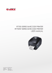
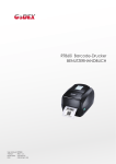
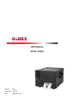
User Manual MAN10xxx-01 User Manual 6416 CONTENTS Page 1 Barcode Printer 1 1.1 Box Content 1 1.2 Getting to Know Your Printer 2 2 Printer Setup 4 2.1 Loading the Label Roll 4 2.2 Loading and Removing the Ribbon 8 2.3 Connecting the Printer to the Host Computer 9 2.4 Installing Printer Driver directly 11 3 Operator panel and Printer Setting 11 3.1 Operator panel – introduction 11 3.2 Function buttons – introduction 11 3.3 Setting Mode 13 3.3.1 Settings mode diagram 17 3.4 Label Calibration and Self Test 18 3.5 Dump mode 19 3.6 Label size calibration 19 3.7 Keyboard mode 20 3.8 Error Alert 22 4 Accessories 24 4.1 Installing the internal rewinder 24 4.2 Installing the label dispenser (6416 with rewinder) 29 4.3 Installing the cutter 32 4.4 Installing the parallel / PS/2 adapter 34 4.5 Installing the applicator interface 36 4.6 Installing the WLAN module 38 5 Maintenance and Adjustment 42 5.1 Installing / Removing the print head module 42 5.2 Adjusting the print line 43 5.3 Adjusting ribbon tension 44 5.4 Cleaning the thermal print head 45 5.5 Adjusting the balance and print head tension 46 5.6 Ribbon shield settings 47 5.7 Cutter settings 48 5.8 CF Card Instruction 48 5.9 Troubleshooting 49 Appendix 50 Product Specifications 50 Interfaces 52 MAN10xxx-01 i User Manual 6416 FCC COMPLIANCE STATEMENT FOR AMERICAN USERS This equipment has been tested and found to comply with the limits for a CLASS A digital device, pursuant to Part 15 of the FCC Rules. These limits are designed to provide reasonable protection against harmful interference when the equipment is operated in a commercial environment. This equipment generates, uses, and can radiate radio frequency energy and, if not installed and used in accordance with the instructions, may cause harmful interference to radio communications. Operation of this equipment in a residential area is likely to cause harmful interference in which case the user will be required to correct the interference at own expense. EMS AND EMI COMPLIANCE STATEMENT FOR EUROPEAN USERS This equipment has been tested and passed with the requirements relating to electromagnetic compatibility based on the standards EN 55022:2006/A1:2007 Class A, EN61000-3-2:2006/A2:2009, EN 61000-3-3:2008 and EN55024:1998/A1:2001/A2:2003, IEC 61000-4-2:2008 series The equipment has also been tested and passed in accordance with the European Standard EN55022 for the both Radiated and Conducted emissions limits. EZ PLUS SERIES TO WHICH THIS DECLARATION RELATES IS IN CONFORMITY WITH THE FOLLOWING STANDARDS IEC 60950-1:2005(2nd Edition)+Am 1:2009, GB4943-2001 GB9254-2008(Class A) GB17625.1-2003, EN 55022:2006/A1:2007 Class A, EN61000-3-2:2006/A2:2009, EN 61000-3-3:2008 and EN55024:1998/A1:2001/A2:2003, IEC 61000-4-2:2008 series, UL 60950-1, 1st Edition, 2007-10-31 CSA C22.2 No. 60950-1-03, 1st Edition, 2006-07, CFR 47, Part 15 WARNING This is a Class A product. In a domestic environment this product may cause radio interference in which case the user may be required to take adequate measures. 此为Class A产品,在生活环境中,该产品可能造成无线电干扰,在这种情况下,可能需要用户对其干扰采取切实可行的 措施。 MAN10xxx-01 ii User Manual 6416 SAFETY INSTRUCTIONS Please read the following instructions carefully. 1. 2. 3. 4. Keep the equipment away from humidity. Before you connect the equipment to the power outlet, please check the voltage of the power source. Make sure the printer is off before plugging the power connector into the power jack. It is recommended that you connect the printer to a surge protector to prevent possible transient overvoltage damage. 5. Be careful not to get liquid on the equipment to avoid electrical shock. 6. For safety and warranty reasons, ONLY qualified service personnel should open the equipment. 7. Do not repair or adjust energized equipment under any circumstances. SPECIFICATIONS ARE SUBJECT TO CHANGE WITHOUT NOTICE. Caution Danger of explosion if battery is incorrectly replaced. Replace only with the equivalent type recommended by the manufacturer. Dispose of used batteries according to the manufacturer’s instructions. Changes or modifications not expressly approved by the party responsible for compliance could void the user's authority to operate the equipment. MAN10xxx-01 iii User Manual 1 6416 Barcode Printer 1.1 Box Content Please check that all of the following items are included with your printer: Compuprint 6416 Barcode Printer Label Stock USB Cable Ribbon Power Cord Empty ribbon core MAN10xxx-01 Compuprint 6416 Quick Guide CD Including Label software, drivers and Compuprint 6416 user manual 1 User Manual 1.2 6416 Getting To Know Your Printer External View 1 2 Operator panel with LCD display Lower cover plate 3 4 Viewing window Printer cover 1 2 3 4 5 6 Feed slot for continuous labels CF card slot Parallel port (optional) WLAN antenna interface (optional) Ethernet port Serial port (DB-9) 7 8 9 10 11 12 PS/2 port (optional) Applicator interface (optional) USB port On/Off switch Power jack Feed slot for continuous labels MAN10xxx-01 2 User Manual 6416 Internal View 1 2 3 4 5 6 Ribbon rewind hub Ribbon supply hub Print mechanism Platen roller Tear-off plate Release lever for print head 1 Movable sensor MAN10xxx-01 7 8 9 10 11 12 3 Adjustment wheel for sensor Paper guide Label tension guide Label supply hub Label roll guide Release catch User Manual 2 6416 Printer Setup This printer supports the following printing methods: Thermal transfer printing (TTP): Requires a ribbon for transferring a printed image to a media. Direct Thermal printing (DTP): Does not requiresa ribbon, only thermal paper. Please check which printing method you are using and after the setting accordingly in the printer driver. Printer menu, and/or software. 2.1 Loading the Label Roll 1. Place the printer on a flat surface and open the printer cover. 2. Pull out the print head release lever as shown in the illustration (1) and turn it anticlockwise to a top right position (2). 3. Pull the release catch for the label roll guide to the right as shown by the blue arrow 1. 4. Now slide the label roll guide forward and fold it up as shown by the blue arrow 2. MAN10xxx-01 4 User Manual 6416 5. Place the label roll on the label supply hub, pushing it right up to the printer housing. (Do not apply too much pressure to avoid damaging the label stock.) 6. Fold the label roll guide back down and push it against the label roll. Note When moving the label roll guide, hold it only by the end that is attached to the bracket, not by its top. 7. Load the label roll into the printer as shown in the illustration. Pass it through the printer as indicated by the blue arrows. 8. Pass the label stock through the sensor and up to the tear-off plate. Note Remember to set the movable sensor to gap, black mark, or tag hole by changing the position of the sensor with the adjustment wheel. MAN10xxx-01 5 User Manual 6416 9. The labels pass between the wall of the printer housing and the adjustable paper guide. Note Pass the labels through the printer as shown in the illustration. 10. Return the print head release lever to its original position. 11. Then close the printer cover. MAN10xxx-01 6 User Manual 6416 2-2 Loading the ribbon 1. Place the printer on a flat surface and open the printer cover. 2. Pull out the print head release lever as shown in the illustration (1) and turn it anticlockwise to a top right position (2). 3. Place a new ribbon on the ribbon supply hub. Then place an empty ribbon core on the ribbon rewind hub. 4. The two illustrations on the right show you how to install the ribbon depending on the ribbon type (ink side in or out). Ink side out 5. Pass the ribbon under the print head and back up on the other side. Attach it to the empty ribbon core. Note Do not pass the ribbon under the sensor. MAN10xxx-01 7 Ink side in User Manual 6416 2-3 Connecting the printer to the host computer 1. Please make sure that the printer is switched off. 2. Connect the power cord to the AC adapter and connect the adapter to the printer. 3. Connect the USB cable to the printer and host computer. 4. Switch on the printer. The operator panel should now light up. MAN10xxx-01 8 User Manual 6416 2-4 Installing the driver 1. Insert the product CD in the CD/DVD drive of the host computer and open the "Windows Drivers" folder on the CD. 2. Select the icon for the driver file and click it to start the installation. 3. Follow the instructions on the screen. The Driver Wizard guides you through the installation procedure. 4. Select "Install printer drivers". 5. Specify your printer model. MAN10xxx-01 9 User Manual 6416 6. Specify the port used to connect the printer to the host computer. 7. Enter a printer name and assign the appropriate rights. 8. Once the installation is complete, a summary of the printer settings is displayed. 9. Check whether the printer settings are correct and click "Finish" to start copying the driver files. 10. Wait until copying is complete, then finish the installation. 11. Once the driver installation is complete, the new printer should be visible in the "Printers and Faxes" folder. MAN10xxx-01 10 User Manual 6416 3. Operator panel and rinter Setting 3-1 Operator panel – introduction 3-2 Function buttons – introduction FEED button When you press the FEED button, the printer moves the label to the defined stop position. If you are using continuous labels, pressing the FEED button will move label stock until you release the button again. If you are using individual labels, pressing the FEED button will move only one label. If the label does not stop at the correct position, you need to run the auto-detection function on the label stock (see Section 3-6). PAUSE button Pressing the PAUSE button while the printer is in standby mode will set the printer to pause mode. The message "Pause" is shown on the LCD display. In this mode, the printer can receive commands, but it can only process them when it is reset to standby mode. Pressing the PAUSE button again will reset the printer to standby mode. Pressing the PAUSE button during printing will interrupt printing. When the PAUSE button is pressed again, the printer resumes printing. Example: While a 10-label print job is running, you press the PAUSE button to pause the printer. Two of the labels have been printed. To resume printing and print the remaining eight labels, you press the PAUSE button again. CANCEL button Pressing the CANCEL button during printing cancels a print job. The message "Print job cancelled" is shown on the LCD display. The current print job is cancelled. Example: While a 10-label print job is running, you press the CANCEL button. Two of the labels have been printed. The print job is cancelled and the remaining eight labels are not printed. MAN10xxx-01 11 User Manual 6416 You can combine the FEED, PAUSE and CANCEL buttons in a number of ways to perform different printer functions: MAN10xxx-01 12 User Manual 6416 3-3 Settings mode In settings mode, you can change different settings, such as the printing mode, accessories / options, or media type. 1. Switch on the printer and make sure that the message "Ready" is shown on the display. 2. Press the PAUSE button and keep it pressed for about 3-4 seconds until you hear 3 beeps and the message "Settings" is shown on the display. 3. In settings mode, the buttons have the following functions: 4. Before you exit settings mode, the printer will prompt you to save the changes you have made. Once you have saved or discarded your changes, the printer will switch back to standby mode. Press the button and keep it pressed for about 3-4 seconds until you hear 3 beeps and the message Settings" is shown on the display. The options available are shown in the lower section of the display. In settings mode, the first line always shows the name of a setting, the second line the current selection or value. To change the current selection or value, press the ENTER button. The current selection or value is highlighted. When you change a setting, the first line shows the name of the setting, the second line the current selection. MAN10xxx-01 13 Plus: The button increases the value. Minus: The button reduces the value. Next: The button switches to the next settings option. User Manual 6416 The following table lists descriptions of the available settings and options: Darkness Speed Stop position Adjust stop position Vertical position Printing mode Accessories / options Paper settings RS232 (serial) settings Sensor type MAN10xxx-01 Default: 10 Sets the temperature during printing. Values range from 0 to 19, the default setting is 10. Sets the print speed (inches per second (ips) Default: 12 The stop position determines how far the printed label is moved out (tear-off position / cut-off position) Default: 0 Adjusts the printer's stop position. Values range from 0 to 10. This value changes the stop position, irrespective of the driver or software settings. Default: 0 Sets the 0 position of the print head. Values range from -100 to 100. Default: Thermal transfer Thermal transfer: Requires a ribbon to transfer a printed image to a label. Direct thermal: No ribbon is required for printing, but a direct thermal print medium must be loaded. Default: Option disabled Dispenser mode: Select to enable the dispenser mode. Cutter mode: Select to enable the cutter mode. Option disabled: Select this setting to disable both options. Default: Die-cut labels Black marks: For labels or normal paper with black marks on the reverse side. Die-cut labels: For die-cut labels on label liner or labels with tag holes Continuous medium: For continuous label stock Baud rate: Default: 9600 bps (bits per second) 4800 bps 9600 bps 19200 bps 38400 bps 57600 bps 115200 bps Parity: Default: None None Odd Even Data length: Default: 8 bits 7 bits 8 bits Stop bit: Default: 1 bit 1 bit 2 bits Default: Automatic Automatic: Automatic detection of label type (labels with black marks, die-cut labels, or continuous label stock) and label height Gap mode: For die-cut labels on label liner or labels with tag holes Reflective mode: For labels or normal paper with black marks on the reverse side. 14 User Manual LCD language Code pages installed Keyboard layout Keyboard mode Buzzer No backfeed Password MAN10xxx-01 6416 Default: English English Simplified Chinese Traditional Chinese Spanish Italian German French Turkish Default: Code page 850 Code page 850 Code page 852 Code page 437 Code page 860 Code page 863 Code page 865 Code page 857 Code page 861 Code page 862 Code page 855 Code page 866 Code page 737 Code page 851 Code page 869 Windows 1252 Windows 1250 Windows 1251 Windows 1253 Windows 1254 Windows 1255 Default: US US (International) English (UK) French German Spanish Italian Finnish Dutch Flemish Retrieve label: Retrieval of a label from the memory Keyboard layout: Layout of the keyboard Code page setting: Code page setting Print option: Print quantity setting Clock setup: Sets the time on the clock shown on the display. Exit keyboard mode: Resets the printer to normal mode and ready to receive print jobs from the host computer. Default: ON ON : Switches beep signals on or off OFF Default: OFF ON: This function requires a dispenser or cutter. OFF Default: OFF ON: When password protection is enabled, you need a password to access the settings. OFF 15 User Manual Top of form USB / Ethernet Preview Lock setup 6416 Default: ON ON: Always starts printing at the top of the page. OFF Default: USB USB: Enables the USB port. Ethernet: Enables the Ethernet port. Lets you preview and check the settings. Locks the value(s) of any setting. When a value is locked, it cannot be altered by changes to the driver or by sending a command. You can lock the following values: EVERYTHING (locks all values) DARKNESS SPEED STOP POS AD STOP POS PRINTHEAD POS PRINTING MODE OPTION SETUP SENSOR SETUP COMPORT SETUP AUTO SENSOR LCD LANGUAGE CODEPAGE KEYBOARD BUZZER SMART BACKFEED TOP OF FORM Note 1 The default settings are the original factory settings. If you have changed the settings, your current settings will be displayed in settings mode. Note 2 The printer will store your changes even after it is switched off. You can change the settings again in settings mode. MAN10xxx-01 16 User Manual 6416 3.3.1 Settings mode diagram Items marked "*" are the default settings. MAN10xxx-01 17 User Manual 6416 3.4 Self Test Label Calibration The printer can automatically detect and store label height. That means the host computer does not need to transmit the label height to the printer. Self Test Self-test function lets you check whether the printer is functioning normally. Here is how you run the label size calibration and self test. 1. 2. 3. 4. Check that the label stock is loaded correctly. Turn off the printer. Turn the printer on again, keeping the FEED button pressed. The printer will now measure the label stock and store the label height. Once the printer has successfully measured the label stock, it will print a self-test label. The contents of a self-test printout are listed below. MAN10xxx-01 18 User Manual 6416 3-5 Dump mode If the label settings do not match the printer output, you should switch the printer to dump mode to check whether an error has occurred during the transfer between printer and host computer. In dump mode, the unprocessed raw data are sent to the printer and printed. This shows you quickly whether any data are sent to the printer at all. Here is how you switch to dump mode: 1. Switch off the printer. 2. Switch on the printer, keeping the FEED button pressed. 3. When the message "Dump Mode" appears on the display, release the FEED button. The printer will automatically print "Dump Mode Begin". That means the printer is now in dump mode. 4. Send commands to the printer and check whether they match the printer output. To exit dump mode, press the FEED button. The printer will automatically print "Out Of Dump Mode" and switch to standby mode. Alternatively, you can switch off the printer to exit dump mode. 3-6 Label size calibration The printer can automatically detect and store label height. That means the host computer does not need to transmit the label height to the printer. 1. Check that the label sensor is positioned correctly. 2. Switch off the printer. 3. Switch on the printer, keeping the PAUSE button pressed. When you hear 3 beeps and the message "Auto Sensing Mode" appears on the display, release the PAUSE button. The printer will now automatically measure the label size and store this information. 4. The label height in mm is shown on the display. After displaying the label height, the printer switches back to standby mode. MAN10xxx-01 19 User Manual 6416 3-7 Keyboard mode The 6416 thermal printer support keyboards with a PS/2 interface, provided the parallel/PS/2 adapter is installed. Here is how you connect a PS/2 keyboard: 1. Switch off the printer and plug the PS/2 connector into the appropriate printer port. 2. Switch on the printer. The message "Keyboard mode [Y/N]" is shown on the display. Press the FEED button on the printer or the ENTER key on the keyboard to switch to keyboard mode. In keyboard mode, you can go back to the previous page at any time by pressing the ESC key on the keyboard or the CANCEL button on the printer. If you keep going back, you will eventually be prompted to exit keyboard mode. To exit keyboard mode, press the ENTER key on the keyboard or the FEED button on the printer when the message "Exit keyboard mode? [Y/N]" appears on the display. To switch back to keyboard mode, either start up the printer again or select "Keyboard mode" in settings mode. If you wish to make any changes to the keyboard settings, please refer to the "Settings diagram" (in Section 3.3) Printing a stored label in keyboard mode ^FTEST1 ^Q100,3 ^W100 ^H10 ^P1 ^S2 ^AD ^C1 ^R0 ~Q+0 ^O0 ^D0 ^E12 ~R200 ^L Dy2-me-dd Th:m:s C0,00001,+1,Serial Number V00,16,Product Name,jc0 V01,16,Price,jc0 AF,330,566,1,1,0,0,^C0 AH,212,168,1,1,0,0,^V00 AG,308,396,1,1,0,0,^V01 E 1. At least one form must be stored in the printer. To create a sample label as shown above, copy the commands in the left-hand column and send them to the printer using HyperTerminal. 2. The sample form contains 2 variables and a serial number: "Product name", "Price" and "Serial Number". Printing will start only when values have been set for all 3 variables. 3. Switch off the printer, connect the PS/2 keyboard to the PS/2 printer port and switch the printer on again. 4. Press "ENTER" to switch to keyboard mode. 5. Press "ENTER" to select a file. *Note: Press .or .to select the previous or next form in the list. 6. The input form for the serial number is now shown on the display. 7. Specify a start value (example: 00001). 8. The input form for the first variable is now shown on the display. MAN10xxx-01 20 User Manual 6416 9. Specify a product name (example: Apple). 10. The input form for the second variable is now shown on the display. 11. Specify a random value (example: 199). 12. The input form for the print quantity is now shown on the display. 13. Specify a quantity (example: 3) 14. The printer will print three labels with the values for the two variables and the serial number specified. MAN10xxx-01 21 User Manual 6416 3.8 Error Alerts In the event of a problem that prevents normal functioning of the printer, you will see an error message on the display and hear some beep signals. The LED indicators above the display will also light up Please refer to below table for the error alerts. Fast flashing Error message displayed Slow Flashing Light on LED above the display RIBBON MEDIA Print head is open Both LEDs light up Entering cooling process Both flashing Beeps Description Solution 4x2 beeps The print mechanism is not closed. Please make sure that the print mechanism is closed correctly. Once the print head has cooled down, the printer switches to standby mode. Please make sure that the printer is set to thermal direct mode. The print head is too hot. No ribbon is loaded. Out of ribbon 3x2 beeps The ribbon is finished or the ribbon roll is not moving. Unable to detect the paper. Out of media 1x2 beeps The labels are finished. Paper jam. CF card not formatted Both flashing Memory full MAN10xxx-01 22 2x2 beeps The CF card is not formatted. 2x2 beeps The memory is full. Replace the ribbon roll. Please make sure that the gap sensor is positioned correctly. If that does not fix the problem, run the auto-detection function again. Replace the label roll. Possible reason: paper feed problem. Please follow the instructions in Section 4-4 to format the CF card. Delete data you no longer need from the memory or use a CF card. User Manual 6416 File name not found 2x2 beeps Unable to find file. Use the "~X4" command to print all file names and check whether the file exists in the memory. File name already exists 2x2 beeps The file name already exists. Change the name of the file and try storing it again. MAN10xxx-01 23 User Manual 6416 4. Accessories 4-1 Installing the internal rewinder 1 2 3 4 5 6 7 8 Motor Rewinder Rewinder connector bracket Retention clip Rewinder guide Cable tie Belt Screws (set of 10) Note For EZ-6200 Plus, the printing speed will be limited to 4 IPS when the rewinder or label dispenser is enabled. 1. Place the printer on a flat surface and open the printer cover. 2. Remove the screws securing the left-hand part of the housing and the printer cover and remove these two parts of the housing. Note Remember to switch off the printer before starting the installation. 3. Remove the connectors from the power supply unit in the two places marked. 4. Remove the two screws that secure the power supply unit on the bottom of the printer housing. 5. Remove the power supply unit. 6. Remove the cable connecting the motherboard and the connector bracket. MAN10xxx-01 24 User Manual 6416 7. Remove the two screws securing the connector bracket from the inside of the printer housing. 8. Now attach the rewinder connector bracket supplied. 9. Connect the rewinder connector bracket to the motherboard as shown in the illustration. 10. Remove the cover for the rewinder module. 11. Remove the retention clip from the rewinder. 12. Secure the rewinder on the printer housing using the four screws supplied. Note. Please make sure that all rewinder cable connectors are arranged on the side of the motherboard before you tighten the screws that secure the rewinder. 13. Connect the "Rewinder full" switch to the jack on the rewinder connector bracket. MAN10xxx-01 25 User Manual 6416 14. Install the motor in the back section of the printer housing and align it with the 4 screw holes. 15. Do not tighten the screws fully, to leave room for installing the belt. 16. If required, adjust the position of the motor during installation of the belt. 17. Now tighten the screws securing the motor. 18. Gently pull the rewinder connection cables so they are fully inside the printer housing. MAN10xxx-01 26 User Manual 6416 19. Connect the cable with the 5-pin connector to the jack marked "CUTTER" on the motherboard. 20. Connect the cable with the 4-pin connector to the jack marked "STRIP" on the motherboard. Connect the remaining connector to the motor. 21. Attach the motor cable and the "Rewinder full" cable to the motor bracket using the cable tie. Note You should position the "Rewinder full" cable underneath the belt to avoid possible faults. 22. Now replace the power supply unit and connect it to the motherboard. 23. Replace the left-hand part of the printer housing and secure it with screws 24. Remove the lower cover plate from the front of the printer by unscrewing the screw marked in the illustration. 25. Remove the lower cover plate. MAN10xxx-01 27 User Manual 6416 26. Mount the rewinder guide on the print mechanism and secure it with screws. 27. Now load the label stock. 28. Pass the label stock through the rewinder from the bottom up. Secure the label stock on the rewinder using the retention clip. Note Make sure you choose the correct rewind direction. 29. Replace the printer cover to complete the installation. Note 1 Before you start using the rewinder, please make sure that you have carried out all steps as shown in the illustrations. Then send the command "^XSET,REWINDER,1" to the printer to enable the rewind function. Note 2 To use the label dispenser, you have to remove the rewinder guide again. MAN10xxx-01 28 User Manual 6416 4-2 Installing the label dispenser (6416 with rewinder) 1 2 3 Dispenser module Cable clips (set of 2) Screws (set of 2) Note The printing speed will be limited to 4 IPS when the rewinder or label dispenser is enabled. 1. Unscrew the screw marked in the illustration on the front of the printer, which secures the lower cover plate. 2. Remove the lower cover plate. Note Switch off the printer before starting the installation. 3. Remove the two screws securing the tear-off plate, then remove the tear-off plate. 4. Secure the dispenser module on the printer using two screws. MAN10xxx-01 29 User Manual 6416 5. Connect the dispenser cable connector to the rewinder jack. 6. Route the connection cable along the bottom of the printer housing using the cable clips. 7. Pull out the print head release lever and turn it anticlockwise to a top right position. 8. Using the lever shown in the illustration (1), fold out the dispenser module in the direction indicated by the arrow (2). 9. Strip a few labels off the label liner (approx. 400 mm) and pass the label liner through the dispenser module. 10. Close the dispenser module again. MAN10xxx-01 30 User Manual 6416 11. Wind the label liner around the rewinder and secure it using the retention clip. 12. Return the print head release lever to its original position. Note. The dispenser can only be used with labels of a minimum height of 20 mm. Suggestion When using the label dispenser, you should set the stop position to 25 mm. 13. Close the printer cover to complete installation of the dispenser. Note Before you start using the rewinder, send the command "^XSET,REWINDER,1" to the printer to enable the rewind function. MAN10xxx-01 31 User Manual 6416 4-3 Installing the cutter 1 2 3 4 Cutter cover Cutter module Cable clips Screws (set of 4) Note 1 Remember to switch off the printer before installing the cutter. Note 2 Do not use to cut adhesive labels! Glue residue will be left on the cutter blade and impair its functioning. The cutter has a blade life of 500,000 cuts when using paper weighing 160 g/m² and 250,000 cuts when using paper weighing 200 g/m². 1. Unscrew the screw marked in the illustration on the front of the printer, which secures the lower cover plate. 2. Remove the lower cover plate. Note Switch off the printer before starting the installation. 3. Remove the two screws securing the tear-off plate, then remove the tear-off plate. MAN10xxx-01 32 User Manual 6416 4. Secure the cutter module on the printer housing using the screws. 5. Connect the cutter cable connector to the cutter jack on the printer. 6. Route the connection cable along the bottom of the printer housing using the cable clips. 7. Place the cutter cover over the cutter module and secure it using the screw you removed from the lower cover plate. 8. Now load the label roll into the printer and close the printer cover. Note 1 Check whether the cutter function is enabled in the printer. Note 2 Labels or paper should be at least 30 mm high. Suggestion After installation of the cutter module, set the stop position to 30 mm . MAN10xxx-01 33 User Manual 6416 4-4 Installing the parallel / PS/2 adapter 1 2 3 4 Parallel cable Parallel / PS/2 adapter Connection cable Screws (set of 2) 1. Check whether the printer is switched off. Place the printer on a flat surface and open the printer cover. 2. Unscrew the two screws marked in the illustration on the right and remove the left-hand side of the printer housing. 3. Unscrew the screws on the parallel port cover and remove the cover. MAN10xxx-01 34 User Manual 6416 4. Install the parallel/PS/2 adapter in its place and secure it on the housing with screws. 5. Connect the 30-pin connection cable to the motherboard. 6. Replace the left-hand part of the printer housing and secure it with the screws you removed earlier. 7. Installation of the parallel/PS/2 adapter is now complete. MAN10xxx-01 35 User Manual 6416 4-5 Installing the applicator interface 1 2 Applicator interface Screws (set of 2) 1. Place the printer on a flat surface and open the printer cover. Note Remember to switch off the printer before starting the installation. 2. Unscrew the two screws marked in the illustration on the right and remove the left-hand side of the printer housing. 3. Unscrew the screws on the applicator interface cover and remove the cover. MAN10xxx-01 36 User Manual 6416 4. Pass the applicator cable through the opening into the housing. 5. Connect the applicator cable to the jack marked "APP" on the motherboard. 6. Secure the applicator interface using two screws. 7. Replace the left-hand part of the printer housing and secure it with the screws you removed earlier to complete the installation. MAN10xxx-01 37 User Manual 6416 4-6 Installing the WLAN module 1 2 3 4 5 6 7 8 9 10 Ethernet Cable 1.8M Secure Screw*2 Bracket Screw*2 Module Bracket WLAN module Module Connection Wire WLAN Antenna Nut (for Antenna) Washer (for Antenna) Antenna Bracket 1. Make sure the power is off and the power cable is unplugged. Place the printer onto a smooth surface and open the top cover. 2. Remove the Left Top Cover from the printer. 3. Remove the covers of Ethernet port and Antenna port from the back plate of the printer. 4. Secure the WLAN module onto the module bracket. MAN10xxx-01 38 User Manual 6416 5. Plug the connector into the socket on WLAN module. 6. Connect the other end of Module Connection Wire to the main board socket. 7. Mount the WLAN module and secure it onto the back plate. 8. Thread Antenna Connection Wire through the hole on the Antenna Bracket. MAN10xxx-01 39 User Manual 6416 9. Mount the Antenna Connection Wire and Antenna Bracket on the back plate and secure it with screws. 10. Put the Washer first and then tighten the Nut on the Antenna Connection Wire. 11. Turn the Antenna according to the direction as arrow showed to mount it on the Antenna Connection Wire. The angle of Antenna can be adjusted if needed. MAN10xxx-01 40 User Manual 6416 12. Reassemble the Left Top Cover to complete the installation. Note 1: After the WLAN module installation is completed, please send the "^lan" printer command to printer for activating the Ethernet connection function. Please mind that USB port will be deactivated once the Ethernet connection function is activated. Note 2: The first time setting operation must be performed with Ethernet (wired) connection before you can access wireless network. MAN10xxx-01 41 User Manual 6416 5. Maintenance and adjustment 5-1 Installing / removing the print head module 1. Open the printer cover. Note Remember to switch off the printer before removing the print head module. 2. Pull out the print head release lever as shown in the illustration (1) and turn it anticlockwise to a top right position (2). 3. Hold the print head module at the front and gently pull it out. 4. If you cannot remove the module by gently pulling it, use a screwdriver as shown in the illustration. 5. Hold the module at the front and slide it into the printer along the guide rails. Firmly press the module in so the contacts are fully connected. MAN10xxx-01 42 User Manual 6416 5-2 Adjusting the print line 1. Open the printer cover. 2. Pull out the print head release lever as shown in the illustration (1) and turn it anticlockwise to a top right position (2). 3. TPH print line adjustment: When printing is slow or when printing on thick label stock, the print line must be moved to the front (in paper feed direction) for a better print result. Using a flat-head screwdriver, turn the screws clockwise to move the TPH forward. The two screws on the left and right must be adjusted to the same position to ensure the print line and feed roller are in parallel. One turn of the screw moves the print head by 0.5 mm. To keep track of the change in quality, you should adjust the screws by ¼ turn at a time. If no improvement is visible, gently turn the screws clockwise as far as possible, then restart the adjustment process from there. MAN10xxx-01 43 User Manual 6416 5-3 Adjusting the ribbon tension You can adjust the ribbon tension by turning the ribbon shaft knob (green wheel at the base of the ribbon supply hub – see illustration) clockwise or anticlockwise. There are 4 possible settings, which are marked on the knob of the ribbon rewind hub and the ribbon supply hub. When set to 1, the tension is highest, while the tension is lowest at 4. If the tension is so low that the ribbon does not move forward, you need to reduce the tension of the ribbon supply hub or increase the tension of the ribbon rewind hub. To set the tension, press in the knob and turn it clockwise or anticlockwise as required. Increasing the tension of the ribbon rewind hub will remove any wrinkling of the ribbon during printing, which results from the use of different ribbon materials. (For details about the wrinkling/creasing of ribbons, see Section 5-6.) If you are using a very narrow ribbon, the printer may not move the label stock forward (particularly with a ribbon that is less than 2" wide). In that case, reduce the tension by turning the knob of the ribbon supply hub anticlockwise. If the tension is too high, the ribbon core may be crushed and thus impossible to remove. In that case, reduce the tension of the ribbon supply hub and the ribbon rewind hub by turning the knobs anticlockwise. MAN10xxx-01 44 User Manual 6416 5-4 Cleaning the thermal print head Dirt on the print head or ribbon may result in inadequate print quality (no printed image on part of the label). The printer cover should therefore be kept closed whenever possible. Keeping dirt and dust away from the paper or labels ensures a good print quality and a longer lifespan of the print head. Here is how you clean the print head: 1. Switch off the printer. 2. Open the printer cover. 3. Remove the ribbon. 4. Release the print head by turning the print head release lever. 5. To remove any label residue or other dirt from the print head (see blue arrow), please use a soft lint-free cloth dipped in alcohol. Note 1 The print head should be cleaned once a week. Note 2 Please make sure that there are no metal fragments or other hard particles on the soft cloth used to clean the print head. MAN10xxx-01 45 User Manual 6416 5-5 Adjusting the balance and print head tension 1. Open the printer side cover. 2. Pull out the print head release lever as shown in the illustration (1) and turn it anticlockwise to a top right position (2). When using a variety of label stock and ribbons, the ink may not be evenly distributed. If there is no printed image on one side of the paper, or the ribbon wrinkles, the print head pressure must be readjusted using the TPH spring boxes. 3. Move the TPH spring boxes as shown in the illustration to change the print head pressure. The wider the medium you are using, the further out the TPH spring boxes must be moved. If there is no quality improvement, you need to change the pressure on the TPH spring boxes. 4. Turning the screw clockwise increases the pressure, while turning it anticlockwise reduces the pressure. MAN10xxx-01 46 User Manual 6416 5-6 Ribbon shield settings 1. The use of different ribbon materials may cause wrinkling of the ribbon, which in turn affects the print result as illustrated by the examples in (a) and (b). To change the print quality, you can adjust the ribbon shield screws. If your print result looks like the example in (a), you need to turn ribbon shield screw A clockwise. If your print result looks like the example in (b), you need to turn ribbon shield screw B clockwise. 2. To keep track of the change in print quality, you should adjust the screws by half a turn at a time. Print a test page. If there is no improvement in the print result, turn the screw by another half turn. Do not turn the adjustment screw more than two full turns. Note If you adjust the screw by more than two full turns, the paper feed may no longer function correctly. In that case, unscrew the ribbon shield screws fully and restart the adjustment process. MAN10xxx-01 47 User Manual 6416 5-7 Cutter settings 1. Socket head screws for adjusting the cutter are located on both sides of the cutter. 2. In the event of a paper jam, the cutter will no longer function correctly. Switch off the printer and use a hex key (#M3) to turn the socket head screw. 3. Turn the key anticlockwise to remove the jammed paper. 4. When you have removed the jammed paper, you can switch the printer back on. The cutter will automatically reset. Note The label medium should be at least 30 mm long to ensure correct functioning of the cutter. 5-8 CF Card Instruction The 6416 thermal printer has a built-in CF Card slot on the back of the printer. If the built-in memory is insufficient for storing label formats, graphics or fonts, users can use CF Card as external memory to provide more memory space. When using the CF card, please follow the instruction as below: 1. 2. 3. 4. 5. Please power off the print before installing or removing CF Card from the card slot. The CF Card cannot be used for printer’s external memory until it is formatted in FAT16. When the printer has detected that the CF card is not formatted in FAT16, the LCD will show the message of “CF card not formatted, press FEED to format”. If user wants to format the CF Card, please follow the instruction to press the “FEED” key, and then the printer will format the CF Card in FAT16. After the format is complete, a file folder named “CF” would be created automatically. This folder is for storing all the data from the printer, please don’t do any change on it. The specification of CF Card that is supported by the printer is as follow: . Compact Flash Type I . Compact Flash (CF) v1.4 specification . Capacity: 128MB ~ 512MB . File system: FAT16 MAN10xxx-01 48 User Manual 6416 5-9 Troubleshooting Problem The printer is switched on but the display does not light up. One or both LEDs lights up red and printing is interrupted. Solution ♦ Check the power supply. ♦ ♦ ♦ Check the software settings (driver settings) or command codes. Look for the error alert in the table in Section 3.8. Error Alerts. Check whether the cutter is functioning normally and whether it is cutting at all. (Only if a cutter is installed.) Please make sure that the label stock is loaded the right way up and that it is suitable material. Please make sure that the ribbon is loaded correctly. Choose the correct printer driver. Choose the correct label stock and a suitable printing mode. Clear the paper jam. Remove any label material left on the thermal print head and clean the print head using a soft lint-free cloth dipped in alcohol. Check the thermal print head for dust or other dirt (label material or ribbon residue). Check for errors in the application software Check the ribbon for wrinkles Check the power supply. Run a self test (Section 3-4.) and check the test print pattern to see whether the print head prints over the entire width of the media. Check the quality of the print media. Run the auto-detection function. (Section 3-6.). Check the label height setting. Check whether there is paper or dust covering the sensor Check the paper guide settings. Check whether the label stock is positioned straight. ♦ Check whether the label is more than 0.16 mm thick. ♦ ♦ Check whether the cutter has been correctly installed. Check whether the paper guides are functioning correctly. Check whether there is dust on the label dispenser Check whether the label stock is positioned correctly. ♦ ♦ ♦ The label stock passes through the printer but no image is printed. ♦ ♦ ♦ ♦ The label stock jams during printing. ♦ There is no printed image on some parts of the label or the image is blurred. The printed image is positioned incorrectly or a label is missed out during printing. The cutter does not cut off the labels in a straight line. The cutter does not cut off the labels completely. When using the cutter, the labels are not fed through or cut off incorrectly. The label dispenser is not functioning normally. ♦ ♦ ♦ ♦ ♦ ♦ ♦ ♦ ♦ ♦ Note ***If any problems occur that are not described above, please contact your dealer. MAN10xxx-01 49 User Manual 6416 APPENDIX Product Specifications Model 6416 Print Method Resolution Print Speed Print Width Print Length Memory Flash SDRAM Sensor Type Types Width Media Ribbon Thickness Label roll diameter Core diameter Types Length Width Ribbon roll diameter Core diameter Printer Language Software Resident Fonts Label design software Driver DLL Bitmap fonts Scalable fonts Bitmap fonts Download Fonts Asian fonts Scalable fonts Barcodes 1-D Bar codes 2-D Bar codes MAN10xxx-01 6416-H Thermal Transfer / Direct Thermal 203 dpi (8 dots/mm) 300 dpi (12 dots/mm) Up to 6 IPS (150 mm/s) Up to 4 IPS (102 mm/s) 6.61” (168 mm) Min. 0.16” (4 mm)** ; Min. 0.16” (4 mm)** ; Max. 118” (3000 mm) Max. 54” (1371 mm) 4MB Flash (2MB for user storage) 16MB SDRAM Adjustable reflective sensor and transmissive sensor, left aligned Continuous form, gap labels, black mark sensing and punched hole: label length set by auto sensing or programming Tear: Min 2” (50,8 mm) Min. – 7” (178 mm) Max. Cutter: Max 6.5” (165 mm) Max. (Heavy duty cutter): 6.8” (172 mm) Max. Dispenser/Rewind : 7” (178 mm) Max. Min 0.003” (0.06 mm) – Max 0.01” (0.25 mm) Label roll diameter: Max. 8” (203.2 mm) with 3" (76.2 mm) core / Max. 6” (152.4 mm) with 1.5" (38.1 mm) core Min 1.5” (38.1 mm) – Max 3” (76.2 mm) Wax, Wax/Resin, Resin Max 1476” (450 m) Width: 2.36” Min - 6.85” (60 mm - 174 mm) Max 3” (76.2 mm) 1” (25.4 mm) EZPL CZL (Compuprint Zebra Language CEL (Compuprint Eltron Language) autoswtching GoLabelCP (for EZPL only) Windows 2000, XP, Vista, Win7, Win8, Windows Server 2003 & 2008 Windows 2000, XP, Vista, Win7, Windows Server 2003 & 2008 6, 8, 10, 12, 14, 18, 24, 30, 16X26 and OCR A & B Bitmap fonts 90°, 180°, 270° rotatable, single characters 90°, 180°, 270° rotatable Bitmap fonts 8 times expandable in horizontal and vertical directions 90°, 180°, 270° rotatable Bitmap fonts 90°, 180°, 270° rotatable, single characters 90°, 180°, 270° rotatable Asian fonts 90°, 180°, 270° rotatable and 8 times expandable in horizontal and vertical directions Scalable fonts 90°, 180°, 270° rotatable Code 39, Code 93, Code 128 (subset A, B, C), UCC/EAN-128 K-Mart, UCC/EAN-128, UPC A / E (add on 2 & 5), I 2 of 5, I 2 of 5 with Shipping Bearer Bars, EAN 8 / 13 (add on 2 & 5), Codabar, Post NET, EAN 128, DUN 14, HIBC, MSI (1 Mod 10), Random Weight, Telepen, FIM, China Postal Code, RPS 128 and GS1 DataBar PDF417, Datamatrix code, MaxiCode, QR code and Micro QR code 50 User Manual Model Code Pages Graphics Interfaces Control Panel Real Time Clock Power Operation Temperature Environment Storage Temperature Operation Humidity Storage Agency Approvals Length Dimension Height Width Weight Options 6416 6416 6416-H CODEPAGE 437, 850, 851, 852, 855, 857, 860, 861, 862, 863, 865, 866, 869, 737 WINDOWS 1250, 1251, 1252, 1253, 1254, 1255 Unicode (UTF8, UTF16)) Resident graphic file types are BMP and PCX, other graphic formats are downloadable from the software Serial port: RS-232 (DB-9) USB port (default on) CF Card socket Ethernet 10/100Mbps print server (default off; disables USB when in use) Backlight graphics LCD display: 128 x 64 dots or 4 lines x 16 characters Three mono-color status-LEDs: Power on, Ribbon out, Media out Control keys: FEED, PAUSE and CANCEL Standard Auto Switching 100-240VAC, 50-60Hz 41°F to 104°F(5°C to 40°C) -4°F to 140°F (-20°C to 60°C) 30-85%, non-condensing 10-90%, non-condensing CE(EMC), FCC Class A, CB, cUL, CCC 20.15” (512 mm) 11.45” (291 mm) 10.78” (274 mm) 33 lbs (15Kg) ,excluding consumables Cutter Module Internal Rewinder with Label Dispenser (peel) Parallel port (Centronics 36-pin) and PS2 port Applicator Interface (1 input, 3 outputs, power 500mA @ 5V) 802.11 b/g wireless print server (Default off; disables USB when in use. Must remove Ethernet card to install) External label roll holder for 10” (250 mm) O.D. label rolls External label rewinder Notice ****Specifications are subject to change without notice. All company and/or product names are trademarks and/or registered trademarks of their respective owners. ****Minimum print height specification compliance can be dependent on non-standard material variables such as label type, thickness, spacing, liner construction, etc. Compuprint is pleased to test non-standard materials for minimum height printing capability. MAN10xxx-01 51 User Manual 6416 INTERFACES Pinout Description USB Connector Type : Type B Pin NO. Function 1 VBUS 2 D- 3 D+ 4 GND Connector Type : Type A Pin NO. Function 1 VBUS 2 D- 3 D+ 4 GND Serial Port (DB9) Default settings: Baud rate 9600, no parity, 8 data bits, 1 stop bit, XON/XOFF protocol and RTS/CTS RS232 Housing (9-pin to 9-pin) DB9 Socket -RXD TXD DTR GND DSR RTS CTS RI Computer 1_____________________________1 2_____________________________2 3_____________________________3 4_____________________________4 5_____________________________5 6_____________________________6 7_____________________________7 8_____________________________8 9_____________________________9 Ethernet (RJ45) PIN N° 1 2 3 4 5 6 7 8 FUNCTION T+ TR+ N/C N/C RN/C N/C Note ****The +5 V total current to the serial port may not exceed 500mA. MAN10xxx-01 52 DB9 Plug +5V (*) TXD RXD N/C GND RTS CTS RTS N/C Printer User Manual 6416 PS/2 port Pin NO. Function 1 DATA 2 N/C 3 GND 4 VCC 5 CLOCK PS/2 computer-to-printer interface Printer DATA N/C GND VCC CLOCK N/C Keyboard DATA N/C GND VCC CLOCK N/C 1 2 3 4 5 6 ________________ ________________ ________________ ________________ ________________ ________________ 1 2 3 4 5 6 UART1 Wafer N/C TXD RXD CTS GND RTS E_MD RTS E_RTS +5V GND +5V 1 2 3 4 5 6 7 8 9 10 11 12 ________________ ________________ ________________ ________________ ________________ ________________ ________________ ________________ ________________ ________________ ________________ ________________ 1 2 3 4 5 6 7 8 9 10 11 12 Ethernet module N/C TXD RXD CTS GND RTS E_MD RTS E_RTS +5V GND +5V UART2 Wafer N/C TXD RXD CTS GND RTS N/C RTS N/C +5V GND +5V 1 2 3 4 5 6 7 8 9 10 11 12 ________________ ________________ ________________ ________________ ________________ ________________ ________________ ________________ ________________ ________________ ________________ ________________ 1 2 3 4 5 6 7 8 9 10 11 12 Add-on module N/C TXD RXD CTS GND RTS N/C RTS N/C +5V GND +5V Internal Interface MAN10xxx-01 53 6 N/C User Manual 6416 Applicator Wafer +5V +24V Printing (out) Print error (out) Printed (out) Print (in) GND N/C GND N/C 1 2 3 4 5 6 7 8 9 10 ________________ ________________ ________________ ________________ ________________ ________________ ________________ ________________ ________________ ________________ Applicator port MAN10xxx-01 54 1 2 3 4 5 6 7 8 9 10 Applicator module +5V +24V Printing Print error Printed Print GND User Manual 6416 Parallel Port PIN N° 1 2 3 4 5 6 7 8 9 10 11 12 13 14 15 16 17 18 FUNCTION /Strobe Data 0 Data 1 Data 2 Data 3 Data 4 Data 5 Data 6 Data 7 /Acknowledge Busy /Paper Empty /Select /auto-Linefeed N/C GND Chassis GND +5V (*) Notice ****The +5 V total current to the parallel port may not exceed 500mA. ****The +24 V total current to the applicator port may not exceed 1.5A. MAN10xxx-01 55 PIN N° 19 20 21 22 23 24 25 26 27 28 29 30 31 32 33 34 35 36 FUNCTION GND GND GND GND GND GND GND GND GND GND GND GND /Initialize /Error GND N/C N/C /Select-in COMPUPRINT s.r.l. Via Cottolengo, 77 10072 Caselle T.se (TO) ITALY SPECIFICATIONS ARE SUBJECT TO CHANGE WITHOUT NOTICE. This manual refers to various company and products by their trade names. In most of the cases, these designations are claimed as trademarks or registered tramarkers by their respective companies. Copyright 2014 COMPUPRINT s.r.l. - Printed in Italy