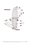
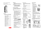
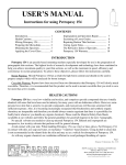
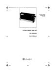
1
Setup and Maintenance Manual June2013 Edition The foundation of airway management has just changed… at the speed of sound. Caution: Federal law restricts this device to sale by or on the order of a physician. This Set-up and Maintenance Manual is an addendum to the Operator’s Manual supplied with the Airwave system and focuses on technical aspects of the system. For information regarding the use of the AirWave in a clinical setting, refer to the Operator’s Manual. WARNING: The instructions in this addendum will allow the user to change the default settings of the Airwave Monitor. Because improvements to this manual and the products it describes will occur, please check that you are using the most current version of this document by visiting www.sonarmed.com. SonarMed, Inc. 12220 N. Meridian Street, Suite 150 Carmel, Indiana 46032 USA Phone: (855) 240-0553 Fax: (866) 853-3684 [email protected] www.sonarmed.com References to “SonarMed” in this manual shall imply SonarMed, Inc. “SonarMed” is a registered trademark, and “AirWave” is a trademark of SonarMed, Inc. SP0621_D AirWave Setup and Maintenance Manual i Table of Contents Table of Contents A. System Description ................................................................................................................................................................... 1 B. Warnings and Precautions ........................................................................................................................................................ 2 C. Airwave Monitor Package Contents .......................................................................................................................................... 2 D. Displays, Indicators, and Controls ............................................................................................................................................. 3 1. AirWave Monitor Controls – Front Panel ............................................................................................................................... 3 2. Airwave Connections – Right Side ........................................................................................................................................ 4 3. AirWave Monitor Screens ...................................................................................................................................................... 4 4. AirWave Monitor Indicators and Icons ................................................................................................................................... 5 5. General Symbols ................................................................................................................................................................... 6 6. Basic Navigation and Editing ................................................................................................................................................. 7 E. System Set-up ........................................................................................................................................................................... 8 1. Powering On the AirWave Monitor ........................................................................................................................................ 8 2. Modifying System Settings .................................................................................................................................................... 8 3. Powering Off the Monitor ..................................................................................................................................................... 10 F. Updating Monitor Firmware ..................................................................................................................................................... 11 1. Necessary items .................................................................................................................................................................. 11 2. Windows Software Installation ............................................................................................................................................. 11 3. Firmware Upgrade ............................................................................................................................................................... 11 G. Cleaning, Maintenance and Disposal ...................................................................................................................................... 12 H. Troubleshooting ...................................................................................................................................................................... 13 1. Error Messages ................................................................................................................................................................... 13 2. AirWave Sensor Health Metric ............................................................................................................................................. 14 3. Data Logging ....................................................................................................................................................................... 15 4. Downloading Data ............................................................................................................................................................... 16 I. Service, Support, and Warranty .............................................................................................................................................. 18 J. Parts and Accessories............................................................................................................................................................. 19 K. Specifications .......................................................................................................................................................................... 20 L. 1. AirWave Monitor .................................................................................................................................................................. 20 2. AirWave Sensor................................................................................................................................................................... 20 3. System Accuracy ................................................................................................................................................................. 21 4. Storage & Operating Conditions .......................................................................................................................................... 21 5. Electromagnetic Compatibility ............................................................................................................................................. 21 Principles of Operation ............................................................................................................................................................ 24 AirWave Setup and Maintenance Manual ii Section A – System Description A. System Description The SonarMed AirWave acoustic airway monitoring system consists of an AirWave Monitor (Monitor) which is used in conjunction with a single-use AirWave Adapter and cable (Sensor). The Monitor contains signal-generating and echo-processing circuitry that uses proprietary software to monitor the position and patency of an endotracheal tube (ETT) via the AirWave Sensor. The Monitor is powered from an external power supply and has a battery backup that will allow the device to function for approximately 120 minutes without external power. The Monitor has a color display which is used to present information about the ETT status. This information can be used in an adjunctive manner to assist with management of the patient’s artificial airway. The Sensor replaces the standard 15-mm connector (also known as the “hub”) that typically comes with each ETT. AirWave Monitor AirWave Sensor and Cable AirWave Setup and Maintenance Manual 1 Section C – Airwave Monitor Package Contents B. Warnings and Precautions The SonarMed AirWave (Monitor and Sensor) is not to be used as a diagnostic tool; it is to be used as an adjunct to airway management only. The SonarMed AirWave is to be used by properly trained personnel only. Do not use an AirWave Sensor if its pouch is open or damaged. Only the SonarMed AC/DC power supply may be used with the SonarMed Monitor. Use of another power supply may put the patient at risk of an electrical hazard. When the Alarm Silence button is pressed, the Monitor speaker is disabled for two (2) minutes even if a new alarm should occur during that period. Pressing the Alarm Silence button a second time does not reactivate the speaker. Some AirWave alarms may be manually disabled by the user. The Monitor will display the message “An Alarm is Off” when this is the case. All alarms that have been disabled are reactivated to their previous settings if the Monitor is powered off and back on. Only connect the Firmware Upgrade Cable to the Monitor when the AirWave system is not connected to a patient. Calibration of the AirWave Sensor must be performed on a clean, unintubated ETT. Failure to do so may cause the AirWave to provide erroneous results. Do not use abrasive cleaning products on the Monitor as this will damage the clear screen cover and degrade visibility of system information. This device is a precision electronic instrument and must be repaired by qualified technical professionals. Field repair of the device is not possible. Do not attempt to open the case or repair the electronics. Opening the case may damage the device and voids the warranty. C. Airwave Monitor Package Contents (1) AirWave Monitor (1) Carrying strap (1) AC/DC Power Supply (1) Hospital Grade Power Cord (1) Firmware Upgrade Cable (RS232 Connection) (1) USB-to-RS232 Converter Cable (1) Software and Documentation CD AirWave Setup and Maintenance Manual 2 Section D – Displays, Indicators, and Controls D. Displays, Indicators, and Controls This section describes the displays, indicators, and controls for the SonarMed AirWave Monitor. 1. AirWave Monitor Controls – Front Panel Alarm LED Alarm Silence Button Display Screen Speaker Function Buttons Navigation Buttons Power Button Control Description Alarm LED This LED flashes red when and alarm condition is present. The LED flashes even if the audible alarms are silenced Display Screen The display screen of the AirWave Monitor is a color LCD. Alarm Silence Button This button is used to temporarily silence audible alarms. Once pressed, the Monitor silences alarm sounds for two minutes (including if a new alarm is triggered during that time). If an alarm condition still exists after two minutes, the audible signal resumes. Note: Pressing the Alarm Silence button a second time DOES NOT reactivate audible alarms. Navigation Buttons The navigation arrows are used to move between user-selectable options on the screen and to change user-editable values and parameters. The center button (also referred to as the Enter button) selects and locks in changes. Speaker The speaker plays audible alarm tones when an alarm condition exists. The speaker is also used to play the real-time signals sensed by the AirWave Sensor microphones. Function Buttons The function buttons provide specific contextual functionality as indicated by the currently display screen icons. Icons appear to the left of these buttons to indicate their current function. Power Button Pressing the power button once turns on the AirWave Monitor. Pressing and holding the power button for one (1) second turns the AirWave Monitor off, discontinuing all monitoring functions. After turning the Monitor off, if the Monitor is plugged into AC power and the battery is not fully charged, the Monitor screen powers back on with a message that the battery is AirWave Setup and Maintenance Manual 3 Section D – Displays, Indicators, and Controls Control Description charging. The monitor can be turned off completely by pressing the power button one more time. 2. Airwave Connections – Right Side AC Power Port PC Communication Port Airwave Adapter Port Port Description AC Power Port This connector accepts the SonarMed AC/DC power supply. Only the SonarMed AC/DC power supply may be used with the SonarMed Monitor. Use of another power supply may put the patient at risk of an electrical hazard. Note: To begin charging the battery, the Monitor must be connected to the AC power source, and the Monitor must be turned on. Plugging in the AC power source to a Monitor that is turned off will not charge the battery. AirWave Sensor Port This connector accepts the SonarMed AirWave Sensor. PC Communication Port This connector accepts the Firmware Upgrade Cable supplied with the SonarMed AirWave Monitor which is used to upgrade system firmware. Only connect the SonarMed AirWave Sensor to this port. The system will not function if another adapter is connected. Only connect the Firmware Upgrade Cable to the Monitor when the AirWave system is not connected to a patient. Only use the Firmware Upgrade Cable supplied by SonarMed. 3. AirWave Monitor Screens System Start-up Screens These screens appear when the unit is first powered on. If no AirWave Sensor is connected to the Monitor, the system prompts to connect one. Once a Sensor is connected, the user is guided through the calibration process to the Patient Monitoring Screen. Patient Monitoring Screen (“Home” screen) This is the primary monitoring screen for the AirWave Monitor. It provides icon-graphical and numerical representation of the status of the ETT including indicators for ETT tip movement, passageway size, and tube obstruction. AirWave Setup and Maintenance Manual 4 Section D – Displays, Indicators, and Controls Waveform Screen This screen provides an alternative visual representation of the information displayed on the Patient Monitoring Screen in the form of the acoustic waveforms being analyzed by the AirWave. System Set-Up Screens These screens, accessed through the Main Menu, provide the interface for editing system parameters. These parameters include alarm limits for ETT tip movement, passageway size, and obstruction, a patient identification number, an ETT length setting, and sound speed correction settings. 4. AirWave Monitor Indicators and Icons Indicators (if applicable) are presented on all screens. Icons appear next to the function keys to provide specific functionality depending on the current screen or action being performed. Indicator/ Symbol Description Battery Indicator – located in the upper left corner of the screen; the number of bars indicates charge level, and the bars blink during charging. External Power Indicator – when this symbol is present near the upper left corner of the screen, the AirWave monitor is plugged into AC power Alarm Silence Indicator – when this symbol is present near the upper left corner of the screen, the alarms on the AirWave Monitor have been muted using the Alarm Silence button. The symbol begins to flash ten seconds prior to the alarms becoming unmuted. Uncalibrated Indicator – located in the upper center of the screen, this indicates that a connected Sensor-ETT pair has not yet been calibrated for use with this Monitor. Calibrated Indicator – located in the upper center of the screen, this indicator appears once a connected Sensor-ETT pair has been calibrated for use with the Monitor. The left value is the ID of the ETT, the right value is the calibrated length of the ETT. Sound Speed Correction Indicator – located in the upper right corner of the screen, this indicator shows the current user defined setting that the AirWave is using to compensate for changes in the speed of sound caused by high oxygen concentrations (FiO2) or the presence of anesthesia gases. LCD Brightness Symbol Time/Date Symbol Button Icon System Action When Pressed [Accept Changes] / [Yes] Icon AirWave Setup and Maintenance Manual 5 Section D – Displays, Indicators, and Controls Button Icon System Action When Pressed [Cancel Changes] / [No] Icon Screen Pixel Test Icon – when pressed, sets all LCD pixels to white to allow examination for dead pixels Main Menu Icon – enters the Main Menu to make changes to user-defined parameters Previous Screen Icon – returns to the last screen that was displayed Next Screen Icon – moves to the next screen in a sequence Return to Defaults Icon – resets the Monitor’s alarm settings to the default values (default values are selected during initial Monitor set-up, typically by the hospital’s Biomedical Engineering Department). System Memory Erase Icon – erases any data stored in system memory as a result of data logging activity 5. General Symbols Symbol Definition WARNING – Refer to this user manual for specific warnings and precautions. Prohibited – Refer to the Contraindications Section of this manual for a complete list of system limitations Single Use Only – the SonarMed AirWave Sensor may not be reused due to risk of infection and/or cross-contamination The SonarMed Sensor is a defibrillation-proof type BF applied part “Use By" date in the format: YYYY-MM Manufacturer symbol AirWave Setup and Maintenance Manual 6 Section D – Displays, Indicators, and Controls 6. Basic Navigation and Editing a. Navigation from screen to screen of the AirWave Monitor occurs in one of two ways: Using the Function Buttons – These buttons provide specific contextual functionality for the current screen and as indicated by the icons displayed to the left of the buttons. Selecting from a list – On the Main Menu Screen, item are selected from a list by using the Navigation Arrows and pressing the Enter button to enter that screen. b. Certain screens of the AirWave Monitor contain fields that can be edited. Navigation between these fields occurs by using the navigation arrows. The active field is designated by a yellow highlight: To edit the field, press the Enter button, which turns the highlight from yellow to white: Modify the field value by using the up and down navigation arrows. In some cases, individual digits of a value are modified separately and the left and right arrows navigate between the digits. To lock in the new value, press the Enter button again. This turns the highlight back to yellow. At this point, the navigation arrows move the focus to different fields to make changes. When exiting the screen (usually by using the Return Arrow function button), the system prompts to accept or cancel any changes. Selecting the green checkmark confirms all modifications made on the screen; the Monitor also plays a confirmatory tone. Selecting the red X returns all values on the screen to their previous values. AirWave Setup and Maintenance Manual 7 Section E – System Set-up E. System Set-up This section describes how to access and modify the AirWave Monitor system settings (screen brightness, date/time, default alarm thresholds, alarm tone, and patient data requirements). 1. Powering On the AirWave Monitor a. Press the power button to turn on the Monitor. b. The Monitor emits an audible tone to test its sound circuitry. The alarm LED flashes red once. c. If any errors are detected during start-up diagnostics, refer to Section H – Troubleshooting. 2. Modifying System Settings a. Access the Main Menu by pressing the top function key as shown below. b. From the Main Menu select System Settings as shown below to advance to the Password Screen. Note that the options displayed in the Main Menu may differ from those shown depending on the selected settings and whether a Sensor is present or not. c. In the Password Screen, enter the password using the Navigation Arrows in the following order: left – up – right. AirWave Setup and Maintenance Manual 8 Section E – System Set-up d. In the System Setting Screen shown below, the following settings can be modified: Screen Brightness: 1 (low) to 10 (high) Date: MM/DD/YY format Time: 24-hour time format (12:00-11:59 PM represented as 12:00 -23:59). Patient ID: Enables access from Main Menu to Patient Info Screen. If this option is enabled (set to “Y”), then all data collected within the Monitor are stamped with a patient identification number which is accessible from the Patient Info Screen. Data Logging: Enables access from Main Menu to the Data Logging Screen. If this option is enabled (set to “Y”), the monitor can be set up for various data collection operations to facilitate troubleshooting (see Section H – Troubleshooting for details). e. When modifications are complete, return to the Main Menu by pressing the Previous Screen Icon or advance to the Default Alarm Settings Screen by pressing the Next Screen Icon. If changes were made, the system prompts to confirm or cancel the changes before moving to the next screen. f. In the Default Alarm Settings Screen shown below, the default alarm values can be modified as follows: ETT Tip Movement: High and low thresholds may be set separately in increments of 0.1 cm Passageway Diameter: High and low thresholds may be set separately in increments of 5% ETT Obstruction: This threshold may be set in increments of 5% Main Alarm Tone: To provide a distinct alarm tone that will differentiate the AirWave alarm from nearby alarms, the alarm tone is selectable from four sequences (A through D). While editing this field, pressing the up/down arrow buttons plays each alarm tone. AirWave Setup and Maintenance Manual 9 Section E – System Set-up Note that these are the default alarm settings to which the system will revert if the user presses the Restore Defaults button in the Alarm Settings Screen. g. When modifications are complete, return to the System Setting Screen by pressing the Previous Screen Icon or advance to the Main Menu by pressing the Next Screen Icon. If changes were made, the system prompts to confirm or cancel the changes before moving to the next screen. 3. Powering Off the Monitor a. Press and hold the power button for at least one second. b. The Monitor displays “Power Down In Progress” for one second and then the screen goes black. c. If the internal battery is not fully charged and the AC/DC Power Supply is still connected, then the Monitor screen powers back on into the battery charging mode. For new units, it is recommended to fully charge the battery before placing the device into service. d. Pressing the power button while in battery charging mode stops charging and powers down the Monitor. e. While in battery charging mode, the Monitor automatically powers down when either the internal battery is fully charged or the AC/DC Power Supply is disconnected. Note: To charge the battery, the Monitor must be connected to the AC/DC Power Supply, and the Monitor must be turned on either in normal mode or battery charging mode. Connecting the AC/DC Power Supply to a Monitor that is turned off will not charge the battery. AirWave Setup and Maintenance Manual 10 Section G – Cleaning, Maintenance and Disposal F. Updating Monitor Firmware In an effort to continually improve the performance of the AirWave system and provide new system features, SonarMed will periodically release new versions of the Monitor firmware. This section provides instructions for upgrading the Monitor firmware. Note: The Monitor firmware version and its unique CRC number is displayed at the bottom of the Password Screen when System Settings is selected in the Main Menu. 1. Necessary items a. Firmware Update Cable (DB-9 to RJ-11). b. USB-to-RS232 Converter Cable (connected to Firmware Update Cable). Note: If necessary, refer to the Parts and Accessories section of this manual for ordering information. c. Software and Documentation CD. d. Firmware Image File X.ldr (e.g. M_1.2.1_CRC149712653.ldr). 2. Windows Software Installation a. Insert the Software and Documentation CD into PC drive. b. Open the Firmware Updater folder, and execute setup.exe to install software on the PC. c. After installation is complete, if the drivers for the USB-to-RS232 Adapter haven’t previously been installed then install them by going to Start►All Programs►SonarMed►USB-RS232 Drivers and selecting the appropriate installation file (WIN98/XP/2000 or Vista/Win7). d. Allow driver to install. e. Connect the USB-to-RS232 Converter Cable to PC and allow driver to finish installing. f. Connect Firmware Update Cable to USB-to-RS232 Converter Cable if not already done. 3. Firmware Upgrade a. Connect RJ-11 side of Firmware Update Cable to the Airwave Monitor. This is the connector that looks like a telephone jack. b. To place Monitor in firmware update mode, start with Monitor turned off and hold down speaker mute button while pressing power button. The alarm LED rapidly blinks yellow and the LCD remains off. If this does not occur, power down the Monitor and retry. c. It is ok to run the Monitor off battery power while updating the firmware. Even if the Monitor loses power while updating, the previous firmware version will remain intact. d. Run Start► All Programs►SonarMed► AirwaveFirmwareUpdater on PC. e. Select the Upload Firmware button. AirWave Setup and Maintenance Manual 11 Section G – Cleaning, Maintenance and Disposal f. Select the firmware image X.ldr and select Open. g. The status window and progress bar shows programming progress. Programming is complete when the Monitor reboots and executes the new firmware image. If the cable accidently becomes disconnected during programming, power down the Monitor by holding down the power button, quit the AirwaveFirmwareUpdater program, and repeat from step b. h. Go to the System Setting Password Screen on the Monitor to verify that the system has been updated to the correct firmware version. The version number and CRC should match the firmware image filename. G. Cleaning, Maintenance and Disposal The Monitor enclosure and AC/DC power supply may be cleaned by lightly rubbing their surfaces with a standard hospital cleaning wipe or a soft cloth dampened with 70% isopropyl alcohol, and then allowed to dry. The Monitor enclosure should be cleaned per the above method between each use from one patient to the next. Do not use any other cleaning solutions as they may degrade the plastic. WARNING: Do not use abrasive cleaning products as this will damage the clear screen cover and degrade visibility of system information. The Monitor contains two batteries: one lithium ion rechargeable battery pack and one coin cell battery used to power the internal clock. These batteries are not user replaceable; contact SonarMed for service. The Monitor must be disposed of in accordance with facility standards and local laws. The Sensor is labeled for single use only. Dispose of the Sensor after use following hospital biohazard policies and local regulations. There are no user serviceable parts in the Monitor. Repairs must be made by SonarMed authorized personnel only. AirWave Setup and Maintenance Manual 12 Section H – Troubleshooting H. Troubleshooting 1. Error Messages When the AirWave system experiences a failure, it displays informational/error messages to assist the user in pinpointing the cause of the problem and determining how to resolve it. The table below lists possible system failures modes, the associated system message (if applicable), if the failure is associated with an audible alarm, and the recommended user action. If the user action doesn’t remedy the problem, please contact SonarMed technical support for assistance. System Message Alarm Description Calibration/Monitoring Messages and Alarms The AirWave cannot obtain a proper Unable to Calibrate calibration signal. ETT Too Low 1 ETT Too High 1 Obstruction Detected 1 Small Passageway (Prior to setting baseline) 2 Small Passageway (After setting baseline) 1 Large Passageway 1 Analyzing… An Alarm is Off Sensor Cable Disconnect ETT Disconnected Excessive Noise Poor Signal Quality Microphone Monitor On 3 The ETT tip has migrated low in the trachea beyond the “ETT Movement – Low” alarm threshold. The ETT tip has migrated high in the trachea beyond the “ETT Movement – High” alarm threshold. An obstruction in the ETT has exceeded the “ETT Obstruction – High” alarm threshold The ETT is in a passageway smaller than the ETT ID. This alarm is intended for use during intubation to provide feedback if the ETT tip is placed in a small passageway such as the esophagus. The ETT is in a passage smaller than the “Passageway Size – Low” alarm threshold. The ETT is in a passage larger than the “Passageway Size – High” alarm threshold This message displays routinely as the Monitor is waiting to receive a clean microphone signal (i.e. between breaths) At least one of the AirWave monitoring alarms is disabled. AirWave Sensor cable is disconnected from Monitor during patient monitoring. The ETT is disconnected from the AirWave Sensor. Excessive noise detected in microphone signals which is preventing collection of data. It is normal for this message to be displayed occasionally. If it occurs continuously for more than one minute then the Monitor is unable to collect data. This is most likely due to excessive ventilator noise, high ventilation rates, or excessive secretions in the airway. Refer to Section F.10 of the AirWave Operator’s Manual for more information. The airway echo amplitude is insufficient for accurate tracking. It is normal for this error to occur occasionally for a few seconds. WARNING! While this error is present, the ETT movement indicator may provide inaccurate readings. The system is playing the microphone signals directly over the Monitor speaker. Patient monitoring is disabled while this message is on. User Action Follow the on-screen prompts to correct the condition causing the failure. If failure persists, replace the AirWave Sensor. Verify condition using alternate airway management techniques; error will clear when condition is corrected. Verify condition using alternate airway management techniques; error will clear when condition is corrected. Verify condition using alternate airway management techniques; error will clear when condition is corrected. Verify condition using alternate airway management techniques; error will clear when condition is corrected. Verify condition using alternate airway management techniques; error will clear when condition is corrected. Verify condition using alternate airway management techniques; error will clear when condition is corrected. None required Re-enable the alarms in the Alarm Settings Screen or cycle the Monitor power. Reconnect Sensor cable to Monitor. Reconnect the ETT. To determine the noise source, listen to the microphone signals via the Monitor AirWave Microphones option in the Main Menu Screen (see Section F.3.c of the AirWave Operator’s Manual). If the source is identified, attempt to reduce the noise level from the source. If this is not feasible, then monitoring on this patient may not be possible. It is possible that a small percentage of patients may exhibit an airway echo of inadequate amplitude that the system may have difficulty tracking accurately. In these patients, it may be necessary to turn off the ETT position tracking alarm. Exit Monitor AirWave Microphones Screen. AirWave Setup and Maintenance Manual 13 Section H – Troubleshooting System Message Alarm Power and Battery Failures N/A Monitor does not power on. N/A Battery Failure Description 3 Charge Battery Battery takes longer than 4 hours to charge. Battery exceeded normal temperature or voltage during charging, or it exceeded the time during which it should have fully charged. System is running on battery and 20% or less charge is remaining. Low Battery 2 System is running on battery and 15% or less charge is remaining. System will automatically shutdown in 60 seconds. AirWave Sensor Failures Heater Failure 3 Heater circuit inside AirWave Sensor is not operating properly. Sx/Change Sensor 3 AirWave microphone(s) and/or speaker are not operating correctly due to electrical malfunction or mucus/water deposition over protective microphone or speaker membranes. It is normal for this error to occur occasionally for a few seconds. System Failures N/A System Error 3 AirWave Sensor is not automatically detected when connected to the Monitor. Internal circuit or software error. Entry Error One or more buttons on the keypad are stuck in the pressed position. Internal memory to which data is being stored has malfunctioned. Test failed during power up that verifies proper operation of alarm speaker. Incorrect value entered in system setup. Internal Clock Fail Internal clock malfunction. Button Stuck Data Flash Error 3 Alarm Speaker Failure 3 User Action Connect Monitor to AC/DC power supply and press on button. If Monitor powers on, leave connected until battery is fully charged. If Monitor doesn’t power on, contact SonarMed technical support Contact SonarMed technical support. Power down Monitor and contact SonarMed for service. Connect Monitor to AC/DC power supply to recharge internal battery. The Monitor can remain connected to a SonarMed Sensor and collect data during battery charge. Connect Monitor to AC/DC power supply to recharge internal battery. The Monitor can remain connected to a SonarMed Sensor and collect data during battery charge. Cycle Monitor power. If error reoccurs try replacing AirWave Sensor. Report error to SonarMed if it persists. If error persists, suction protective membranes inside AirWave Sensor lumen to remove mucus. If this does not clear the error then replace AirWave Sensor. Contact SonarMed technical support. Power cycle Monitor and contact SonarMed for service if error persists. Power down Monitor and contact SonarMed for service if error persists. If this error persists, power down monitor and contact SonarMed for service. Power down Monitor and contact SonarMed for service. Retry entry using correct value. Power down Monitor and contact SonarMed for service. Use the up and down keys only. The wrong button was used to edit a parameter An inappropriate value was entered for Invalid Date or Time Correct the entry in question. one of the parts of the date or time (e.g. month = 13 or hour = 26) 1 – User selectable alarm sound sequence (see AirWave System Set-up and Maintenance Manual for details on selecting alarm type) 2 – Urgent alarm (short, high-pitched tones) 3 – User Action Required alarm Use Up/Down Keys to Edit 2. AirWave Sensor Health Metric When the AirWave Sensor is placed in the breathing circuit, it is probable that secretions will occasionally occlude the acoustic components of the Sensor. Such occlusions can degrade the performance of the System and eventually result in erroneous feedback to the user. To avoid this, the AirWave System continually checks the quality of the acoustic signals and suspends patient monitoring if signal quality drops too much. In this situation, the System displays the error message “Sx /Change Sensor”. AirWave Setup and Maintenance Manual 14 Section H – Troubleshooting To provide further guidance, the System also provides a troubleshooting graphic to assist in determining where within the sensor to focus the suctioning/cleaning efforts. This visual aide looks as follows: When the “Sx/Change Sensor” error is active, this graphic will automatically be overlaid onto the Patient Monitoring Screen to further alert the user to the condition of the Sensor. It will only go away after the Sensor health has returned to an acceptable level to resume monitoring. The Sensor Health graphic is also accessible at any time from the Waveform Screen by selecting the Sensor Health icon (center function button). Since the waveforms may still provide useful troubleshooting information even while monitoring is suspended, the Sensor Health graphic will not automatically appear on the Waveform Screen. The Sensor Health graphic depicts a representation of the AirWave Sensor when seen through the lumen from below. The three boxes show locations of the speaker and the two microphones within the Sensor along with a numeric representation of the performance of each. When all three numbers are green, the Sensor is functioning within acceptable limits. When one or more of the numbers are red, the Sensor requires cleaning. Knowing which of the three components is affected allows the user to specifically target the lavage and suctioning to the correct component, which should make the cleaning process more effective. Once the affected component is clean, its number should return to green. It is possible that cleaning/suctioning will not allow the Sensor health numbers to recover sufficiently to resume monitoring. If this is the case, it will be necessary to replace the Sensor. 3. Data Logging The AirWave contains nonvolatile memory into which monitoring data can be logged at selected intervals. Data logging provides a means for SonarMed technical service personnel to remotely troubleshoot AirWave operation. If the AirWave is frequently displaying error messages or is not performing as expected, it is recommended that data logging be activated and the data be periodically downloaded from the AirWave and sent to SonarMed for analysis. The data logging feature is enabled in System Settings (See Section E.2). a. To access the Data Logging Screen to set the logging parameters, select Data Logging from the Main Menu. AirWave Setup and Maintenance Manual 15 Section H – Troubleshooting b. The Logging mode can be set to one of three options: Off No logging takes place Periodic The system records individual measurements at pre-set intervals Continuous The system records every measurement; note that memory will fill up quickly in this mode c. If using the Periodic logging mode, the user can choose from a selection of time intervals ranging from 5 seconds to 3 minutes. Based on the logging period and the amount of free memory, the text below the parameter box will provide an estimate of the time remaining until the memory becomes full. d. If the Noise Logging feature is turned on, the system will automatically record noise-related data (data stream) when the “Excessive Noise” message is encountered. This can assist SonarMed technical personnel in identifying the cause of the message since noise can originate from a number of sources both inside and outside the patient. Since a data stream uses a large amount of memory (~10%), only one automatic recording is taken in a 12-hour period (unless the Monitor is powered down, which resets the clock). e. The system memory can be erased by pushing the bottom function key. The system prompts the user to confirm prior to erasing, WARNING! Erasing the system memory causes a permanent loss of the data. Any data stored in the system should be downloaded prior to erasing (see Section H.4 for additional details). Note: The amount of memory remaining is displayed in the Monitor’s upper right corner while data logging is enabled. This number will be yellow if Logging is set to Off and green if it is set to Periodic or Continuous. The Monitor will alarm when the system memory is almost full. If the memory becomes full then data logging will stop. f. Once Data Logging parameters are set, exit to the Main Menu by selecting the Return Arrow. The system will prompt the user to confirm changes. 4. Downloading Data In order for SonarMed technical personnel to analyze logged data, the data must be downloaded from the Monitor and sent to SonarMed. a. Necessary Items Firmware Update Cable (DB-9 to RJ-11). USB-to-RS232 Converter Cable (connected to Firmware Update Cable). Note: If necessary, refer to the Parts and Accessories section of this manual for ordering information. Software and Documentation CD. AirWave Setup and Maintenance Manual 16 Section H – Troubleshooting b. Windows Software Installation Insert the Software and Documentation CD into PC drive. Open the AirWave Downloader folder, and execute setup.exe to install software on the PC. After installation is complete, if the drivers for the USB-to-RS232 Adapter haven’t previously been installed then install them by going to Start►All Programs►SonarMed►USB-RS232 Drivers and selecting the appropriate installation file (WIN98/XP/2000 or Vista/Win7). Allow driver to install. Connect the USB-to-RS232 Converter Cable to PC and allow driver to finish installing. Connect Firmware Update Cable to USB-to-RS232 Converter Cable if not already done. c. Data Download Procedure Connect RJ-11 side of Firmware Update Cable to the Airwave Monitor. This is the connector that looks like a telephone jack. Power on the Monitor if it is not already on. It is ok to run the Monitor off battery power while downloading data. However, large amounts of data may take several minutes to download, so connecting the power cord may be desirable if the battery is very low. Run Start► All Programs►SonarMed► AirwaveDownloader on PC. Select the Download Patient History button. Select a location to save the data file, and hit “OK”. The status window and progress bar show downloading progress, and the Monitor screen will show “Log download in progress…”. The download is complete when the file name (.bin) is displayed over the progress bar. If the cable accidently becomes disconnected during programming, quit the AirwaveDownloader program, and repeat this procedure. Select the Download Error Log button. Select a location to save the data file, and hit “OK”. The download is complete when the file name (.txt) is displayed over the progress bar. d. Sending Data to SonarMed Compress data files (.bin and .txt) into a zip file (.zip) Email the data file to [email protected] along with a description of the reason for logging the data. AirWave Setup and Maintenance Manual 17 Section I – Service, Support, and Warranty I. Service, Support, and Warranty WARNING: This device is a precision electronic instrument and must be repaired by qualified technical professionals. Field repair of the device is not possible. Do not attempt to open the case or repair the electronics. Opening the case may damage the device and void the warranty. A return authorization number is required before returning any product to SonarMed. To obtain this return authorization number, contact SonarMed Customer Support: SonarMed, Inc. 12220 N. Meridian Street, Suite 150 Carmel, Indiana 46032 USA Phone: (855) 240-0553 Fax: (866) 853-3684 [email protected] www.sonarmed.com Warranty SonarMed, Incorporated, (SonarMed) warrants to the purchaser, for a period of one year from the date of purchase, each AirWave Monitor battery pack. SonarMed warrants to the purchaser that the AirWave Sensor will calibrate on a clean unused endotracheal tube a minimum of one (1) time when used before the expiration date listed on the package and if the original packaging is not damaged. SonarMed warrants the AirWave Monitor for a period of three years from the date of purchase from an authorized SonarMed distributor as follows: SonarMed shall repair or replace any AirWave Monitor found to be defective in accordance with this warranty, free of charge, for which SonarMed has been notified by the purchaser by serial number that there is a defect, provided said notification occurs within the applicable warranty period. This warranty shall be the sole and exclusive remedy by the purchaser hereunder for any AirWave delivered to the purchaser which is found to be defective in any manner, whether such remedies be in contract, tort, or by law. This warranty excludes cost of delivery to and from SonarMed. All repaired units shall be received by the purchaser at SonarMed's place of business. SonarMed reserves the right to charge a fee for a warranty repair request on any AirWave that is found to be within specifications. The AirWave is a precision electronic instrument and must be repaired by qualified technical professionals. Accordingly, any sign or evidence of opening the AirWave, field service by non-authorized personnel, tampering, or any kind of misuse or abuse of the AirWave, shall void the warranty in its entirety. All non-warranty work shall be done according to SonarMed standard rates and charges in effect at the time of delivery to SonarMed. Disclaimer/Exclusivity of Warranty: The express warranties set forth in this manual are exclusive, and no other warranties of any kind, whether statutory, written, oral, or implied, including warranties of fitness for a particular purpose or merchantability, shall apply. AirWave Setup and Maintenance Manual 18 Section J – Parts and Accessories J. Parts and Accessories The following parts and accessories are available for use with AirWave airway monitoring system. Please contact your distributor representative for pricing and to place an order. Part Description Part Number AirWave Sensor – Small (box of 10) AW-S0001 AirWave Sensor – Medium (box of 10) AW-S0002 AirWave Sensor – Large (box of 10) AW-S0003 AC/DC Power Supply with Power Cord AW-X0007 Firmware Upgrade Cable AW-X0005 RS232 to USB Converter Cable AW-X0006 Monitor Carrying Strap AW-X0004 Standard Adapter Removal Tool (StART) AW-X0001 Monitor Post/Rail Mount (Swivel/Tilt) AW-X0008 Monitor Post/Rail Mount (Gooseneck) AW-X0009 AirWave Setup and Maintenance Manual 19 Section L – Principles of Operation K. Specifications 1. AirWave Monitor Characteristics Functional Specification Size 9.625” x 4.5” x 2.25” Weight 1.9 lb (863 g) Power AC line and battery operation. AC/DC Adaptor Input 100 - 250 VAC 50/60Hz AC/DC Adaptor Output 5 A, 5 V DC Battery Type Single cell lithium ion Battery Run Time 2 hours on fully charged battery Battery Charge Time 1.5 hours typical Mode of Operation Continuous Water Ingress Protection1 IPX-1 Enclosure Leakage Current < 300 μA at 240 VAC Applied Part Classification Type BF, Defibrillation proof Power Classification Monitor: Internally powered or powered from specified supply Power Supply: Class II 2. AirWave Sensor Characteristics Functional Specification Single use Do not re-sterilize or re-use Latex free NA Size 3.5” x 1” x 1.25” / 8.9 x 2.5 x 3.2 cm (with airway connectors) 2.125” x 1” x 1.25” / 5.4 x 2.5 x 3.2 cm (without airway connectors) Weight 4.2 oz / 119 g (with cable) 1.1 oz / 32 g (without cable) 1 IPX-1 Water Ingress Protection rating is for the Monitor only. AirWave Setup and Maintenance Manual 20 Section L – Principles of Operation 3. System Accuracy Accuracy (95% Confidence) Indicator ETT Tip Movement (cm) ± 1.9 cm ETT Obstruction (%) ± 15%1 Passageway Diameter2 (mm) ± 25%3 1 – Percentage is absolute. For example, if actual obstruction is 50% of ETT cross-sectional area, then accuracy is 35% to 65%. 2 – Passageway cross-sectional area is represented as effective passageway diameter. Actual passageway geometry may not have a circular cross-section. 3 – Percentage of passageway diameter. For example, if actual diameter is 10.0 mm, then accuracy is 7.5 mm to 12.5 mm. 4. Storage & Operating Conditions When not in use, the SonarMed AirWave is to be stored under the following conditions: Temperature: Relative Humidity: Atmospheric Pressure: -40 to +70 °C 10% to 100% 50 to 106 kPa The Monitor may be used under the following conditions: Temperature: Relative Humidity: Atmospheric Pressure: +10 to +40 °C 30% to 75% 70 to 106 kPa 5. Electromagnetic Compatibility The information contained in this section (such as separation distances) is in general specifically written with regard to the SonarMed AirWave. The numbers provided will not guarantee faultless operation but should provide reasonable assurance of such. This information may not be applicable to other medical electrical equipment; older equipment may be particularly susceptible to interference. Medical electrical equipment requires special precautions regarding electromagnetic compatibility (EMC) and needs to be installed and put into service according to the EMC information provided in this document and the remainders of the instructions for use of this device. Portable and mobile RF communications equipment can affect medical electrical equipment. Cables and accessories not specified within the instructions for use are not authorized. Using other cables and/or accessories may adversely impact safety, performance and electromagnetic compatibility (increased emission and decreased immunity). Care should be taken if the equipment is used adjacent to or stacked with other equipment; if adjacent or stacked use is inevitable, the equipment should be observed to verify normal operation in the configuration in which it will be used. It is intended for all qualified personnel using the SonarMed AirWave to leave the plastic surround installed around the Monitor’s perimeter at all times. AirWave Setup and Maintenance Manual 21 Section L – Principles of Operation Electromagnetic Emissions This equipment is intended for use in the electromagnetic environment specified below. The user of this equipment should assure that it is used in the specified environment. Emissions Compliance according to Electromagnetic environment RF emissions (CISPR 11) Group 1 The equipment uses RF energy only for its internal function. Therefore, its RF emissions are very low and are not likely to cause any interference in nearby electronic equipment. CISPR Emissions Classification Class A The SonarMed Airway Monitoring System is suitable for use in all establishments other than domestic and those directly connected to the public low-voltage power supply network that supplies buildings used for domestic purposes. Harmonic emissions (IEC 61000-3-2) Not applicable Voltage fluctuations / flicker (IEC 61000-3-3) Not applicable Electromagnetic Immunity This equipment is intended for use in the electromagnetic environment specified below. The user of this equipment should assure that it is used in the specified environment. Immunity against IEC 60601-1-2 test level Compliance level (of this device) Electromagnetic environment electrostatic discharge, ESD (IEC 61000-4-2) contact discharge: 6 kV 6 kV air discharge: 8 kV 8 kV Floors should be wood, concrete, or ceramic tile. If floors are covered with synthetic material, the relative humidity should be kept at levels to reduce electrostatic charge to suitable levels. electrical fast transients / bursts (IEC 61000-4-4) power supply lines: 2 kV 2 kV longer input / output lines: 1 kV Mains power quality should be that of a typical commercial or hospital environment. 1 kV surges on AC mains lines (IEC 61000-4-5) Common mode: 2 kV 2 kV differential mode: 1 kV 1 kV power frequency magnetic field 50/60 Hz (IEC 61000-4-8) 3 A/m 3 A/m Equipment which emits high levels of power line magnetic fields (in excess of 3A/m) should be kept at a distance to reduce the likelihood of interference voltage dips and short interruptions on AC mains input lines (IEC 61000-4-11) dip >95%, 0.5 periods >95%, 0.5 per. dip 60%, 5 periods 60%, 5 per. dip 30%, 25 periods 30%, 25 per. dip >95%, 5 seconds >95%, 5 sec. Mains power should be that of a typical commercial or hospital environment. If user requires continued operation during power mains interruptions ensure that batteries are installed and charged. Ensure that battery life exceeds longest anticipated power outages or provide and additional uninterruptible power source. Mains power quality should be that of a typical commercial or hospital environment. Electromagnetic Environment This equipment is intended for use in the electromagnetic environment specified below. The customer or the user should assure that it is used in the specified environment. Portable and mobile RF communications equipment should be used no closer to any part of the SonarMed Airway Monitoring System, including cables, than the recommended separation distance calculated from the equation applicable to the frequency of the transmitter as below. AirWave Setup and Maintenance Manual 22 Section L – Principles of Operation Immunity test IEC 60601-1-2 test level Compliance level Recommended separation distance Conducted RF coupled into lines (IEC 61000-4-6) 150 kHz – 80 MHz 3V d=1.2P Radiated RF (IEC 61000-4-3) 80 MHz – 2.5 GHz 3 V/m d=1.2P 80 MHz to 800MHz d=2.3P 800 MHz to 2.5 GHz where P is the maximum output power rating of the transmitter in watts (W) according to the transmitter manufacturer and d is the recommended separation distance in meters (m). Field strengths from fixed RF transmitters, as determined by an electromagnetic site surveya, should be less than the compliance level in each frequency rangeb. Interference may occur in the vicinity of equipment marked with the following symbol: NOTE 1 At 80 MHz and 800 MHz, the higher frequency range applies. NOTE 2 These guidelines may not apply in all situations. Electromagnetic propagation is affected by absorption and reflection from structures, objects and people. a. The ISM (industrial, scientific and medical) bands between 150 kHz and 80 MHz are 6,765 MHz to 6,795 MHz; 13,553 MHz to 13,567 MHz; 26,957 MHz to 27,283 MHz; and 40,66 MHz to 40,70 MHz. b. The compliance levels in the ISM frequency bands between 150 kHz and 80 MHz and in the frequency range 80 MHz to 2.5 GHz are intended to decrease the likelihood that mobile/portable communications equipment could cause interference if it is inadvertently brought into patient areas. For this reason, an additional factor of 10/3 is used in calculating the recommended separation distance for transmitters in these frequency ranges. c. Field strengths from fixed transmitters, such as base stations for radio (cellular/cordless) telephones and land mobile radios, amateur radio, AM and FM radio broadcast and TV broadcast cannot be predicted theoretically with accuracy. To assess the electromagnetic environment due to fixed RF transmitters, an electromagnetic site survey should be considered. If the measured field strength in the location in which the system is used exceeds the applicable RF compliance level above, the system should be observed to verify normal operation. If abnormal performance is observed, additional measures may be necessary, such as reorienting or relocating the system. d. Over the frequency range 150 kHz to 80 MHz, field strengths should be less than [V1] V/m. Recommended separation distances between portable and mobile RF communications equipment and the equipment Rated maximum output power of transmitter W Separation distance according to frequency of transmitters in meters 150 kHz – 80 MHz d=1.2P 80 MHz to 800MHz d=1.2P 800 MHz to 2.5 GHz d=2.3P 0.01 0.12 0.12 0.23 0.1 0.38 0.38 0.73 1 1.2 1.2 2.3 10 3.8 3.8 7.3 100 12 12 23 For transmitters rated at a maximum output power not listed above, the recommended separation distance d in meters (m) can be determined using the equation applicable to the frequency of the transmitter, where P is the maximum output power rating of the transmitter in watts (W) according to the transmitter manufacturer. NOTE 1 At 80 MHz and 800 MHz, the separation distance for the higher frequency range applies. NOTE 2 The ISM (industrial, scientific and medical) bands between 150 kHz and 80 MHz are 6,765 MHz to 6,795 MHz; 13,553 MHz to 13,567 MHz; 26,957 MHz to 27,283 MHz; and 40,66 MHz to 40,70 MHz. NOTE 3 An additional factor of 10/3 is used in calculating the recommended separation distance for transmitters in the ISM frequency bands between 150 kHz and 80 MHz and in the frequency range 80 MHz to 2.5 GHz to decrease the likelihood that mobile/portable communications equipment could cause interference if it is inadvertently brought into patient areas. NOTE 4 These guidelines may not apply in all situations. Electromagnetic propagation is affected by absorption and reflection from structures, objects and people. AirWave Setup and Maintenance Manual 23 Section L – Principles of Operation L. Principles of Operation The AirWave System The SonarMed AirWave system, as shown in the Figure below, consists of an AirWave Sensor connected to the proximal end of an ETT, and a Monitor to which the Sensor is connected via a cable. Inside the AirWave Sensor are embedded a miniature speaker, for emitting sound waves into the ETT, and microphones, for sensing the returning echoes. The amplitudes and timing of the echoes are analyzed by the Monitor to provide the following information: location and size of ETT obstructions size of the passageway around the ETT tip relative movements of the ETT tip within the trachea SonarMed AirWave System During use of the AirWave, an option is provided via the Patient Monitoring Waveform Screen to view the echo signal to provide a means to the user to verify that the signal is free of artifact and that the algorithm is properly identifying and tracking the ETT and the patient’s airway echoes (refer to the AirWave System Operator’s Manual for further information). This primer is intended to help the user to better understand and interpret the AirWave echo signals. Acoustic Reflectometry The SonarMed AirWave employs the technique of acoustic reflectometry which consists of emitting acoustic waves into an unknown object (or in this case, an intubated ETT), detecting the returning acoustic reflections (echoes), and examining their timing and amplitudes to infer characteristics of the object in question. As mentioned above, the AirWave Sensor contains a speaker, for generating acoustic waves which travel into the ETT and airways, and two microphones (separated by a small distance), for converting the reflected waves into an echo signal which is input into the Monitor’s proprietary algorithms. This echo signal consists of positive and negative deflections that represent positive and negative sound pressure waves, respectively. The use of two microphones to sense the acoustic waves allows the system to determine the direction from which echoes arrive. As a result, the system can selectively filter all echoes that arise from devices on the ventilator side of the Sensor, such as closed-circuit suction catheters, y-connectors, ETCO2 sensors, filters, etc. This selective filtering is critical for obtaining a clean echo waveform from the ETT and airways that is free of ventilator circuit echoes. Origin of Echoes inside Tubes A key property of an acoustic wave propagating in a tube is that a fraction of the wave’s energy will undergo a reflection each time it encounters a change in cross-sectional area (A). If the changing A is from larger to smaller (as depicted in (a) of the Figure below), a positive pressure wave is reflected (showing up as a positive deflection in the echo signal). Conversely, if the changing A is from smaller to larger (see (b) in Figure below), a negative pressure wave is reflected (showing up as a negative deflection in the echo signal). The delay time of each echo identifies the AirWave Setup and Maintenance Manual 24 Section L – Principles of Operation distance of the changing A that caused the echo. The amplitude of each echo identifies approximately how much the corresponding A changed. (a) (b) Reflection or echo signals that arise from a tube with (a) changing A from large to small and (b) changing A from small to large. Echoes in the ETT and Airways The human airways consist of a network of bifurcating branches that start at the trachea and terminate at the alveoli— small sacs where oxygen-carbon dioxide exchange takes place. An interesting property of the airways is that even though the A of each individual segment decreases as the branching depth increases, the total A (adding As of all parallel segments) undergoes a rapid increase after several generations of airway branching. Considering this morphology, the airways behave acoustically like a horn with a bell at the end. Therefore, acoustic waves traveling down the airways, or the analogous horn model, will be reflected at the rapid increase in total A. The negative pressure wave from this bell-shaped region is used as a reference to which changes in ETT tip position are tracked. The bell begins around the 6th branching generation which is approximately 5 cm past the carina in adults. It is worth noting that there are no echoes of significance that arise from the carina, since the additive A of the two mainstem bronchi is approximately equal to the trachea A. To illustrate the relationships between cross-sectional area, amplitude, and time delay, refer to the Figure below depicting an intubated ETT with a corresponding echo signal (pressure amplitude on y-axis and time delay on x-axis). For each deflection in the echo signal, an arrow denotes the corresponding region in the ETT and airways from which that echo arises. Relationship of AirWave Sensor and intubated ETT (top) to the corresponding echo signal recorded by the AirWave system (bottom). The first (leftmost) nozzle echo is a positive deflection (positive pressure) which indicates an A change within the nozzle from larger to smaller. This corresponds to the diameter change within the nozzle from 9 to 8 mm ID. The second echo is a positive deflection immediately followed by a negative deflection which indicates an A change from larger to smaller and then back to larger. This echo could be from a small obstruction within the ETT, a kink in the ETT, or a patient biting on the ETT. If the echo amplitude were larger, this would correspond to a larger obstruction. The AirWave system estimates the obstruction size from the echo amplitude and the obstruction location from the echo delay time. The third echo is a negative deflection which indicates an A change from smaller to larger. This echo, referred to as the ETT tip echo, is analyzed by the AirWave system to estimate the passageway size (effective diameter) around the ETT. A negative deflection echo indicates that the ETT is located within a passageway that has a larger A compared to the ETT (this would be the case for an ETT in the trachea). If this echo were to change to a positive deflection, AirWave Setup and Maintenance Manual 25 Section L – Principles of Operation then this would indicate that the ETT is located within a passageway that has a smaller A compared to the ETT. This may correspond to an ETT that is in the esophagus or bronchus, or that is clogged at the tip, such as from mucus. The last echo, referred to as the airway echo, arises from the aforementioned bell-shaped region in the airways. The AirWave system tracks the time delay of the airway echo to estimate relative changes in the distance between the ETT tip and the airway echo region. For example, if the time delay between the ETT tip echo and the airway echo is decreasing (airway echo moves to the left), then this indicates that the ETT tip is getting closer to the airway echo region, or that the ETT is migrating down the trachea. All Lungs Are Not the Same Accurate tracking of the airway echo by the system assumes that the echo shape remains consistent over the duration of patient monitoring. Significant changes in the echo shape may result in the system reporting a change in ETT position when the actual position has not changed. It is possible that the airway echo shape may change due to airway changes that affect the geometry of the airway echo region. Some examples of airway changes that may affect the airway echo shape include mucus plugs in a bronchus, or a significant change in middle airway A due to bronchoconstriction or dilation. Therefore, when the system indicates ETT movement, it is recommended that the user enter the Patient Monitoring Waveform Screen (refer to the AirWave System Operator’s Manual for further information) to compare the baseline and present airway echoes to confirm the current echo has shifted in time (moved left/right compared to the baseline echo) and that the baseline and current airway echoes have similar shapes. AirWave Sounds are Audible While a majority of medical devices that employ acoustics do so in the ultrasonic frequency range, the AirWave operates in the audible range below 8 kHz due to reasons related to the frequencies at which tubes behave as waveguides. Operating in these frequencies creates a challenge for collecting echo signals that are not corrupted by the sounds typically found within a ventilator circuit, such as respiratory sounds, secretion sounds, cuff leak sounds, etc. As a result, the AirWave system uses a variety of data collection strategies to collect a clean echo signal during ventilation. When connected to a patient, the system collects a majority of its measurements during the quiet period of ventilation between end-expiration and inspiration. Therefore, the AirWave Monitor provides updates to the ETT status approximately every patient breath depending on the level of noise present between breaths. For cases where excessive noise interferes with acoustical measurements such that the ETT status is not updating, it is recommended that the user enter the Listen to AirWave Microphones Screen to listen directly to the Sensor microphones via the Monitor speaker (refer to the AirWave System Operator’s Manual for further information). This assists the user in determining the noise source so they can rectify it if possible. Examples of noise sources may include: a leaky ETT cuff, secretions in the airway and/or ETT, a high respiratory rate, a nebulizer, and patient coughing. AirWave Setup and Maintenance Manual 26