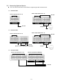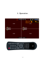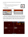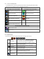
1
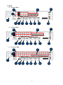
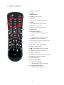
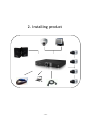
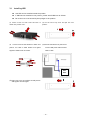
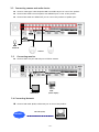
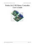
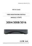
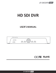
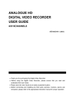
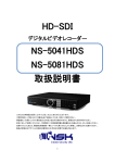
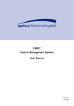
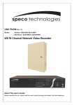
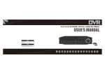
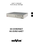
Real time Digital Video recorder DIGITIAL VIDEO RECORDER USER’S MANUAL RoHS -1- Important Safety Instructions. z Read and Keep these instructions z Heed all warnings z Follow all the instructions z Do not use this apparatus near water and Clean only with dry cloth z Do not install near any heat sources such as radiators, heat registers, or other apparatus that produce heat z Protect the power cord from being walked on or pinched particularly at plugs, convenience receptacles, and the point where they exit from the apparatus. z Unplug this apparatus. When a cart is used, use caution when moving the cart/apparatus combination to avoid injury from tip-over. TO REDUCE THE RISK OF ELECTRIC SHOCK, DO NOT REMOVE. NO USER-SERVICEABLE PARTS ARE INSIDE. REFER SERVICING TO QUALIFIED SERVICE PERSONNEL. The lightning flash with an arrowhead symbol within an equilateral triangle is intended to alert the user to the presence of uninsulated “ dangerous voltage” within the product’s enclosure that may be of sufficient magnitude to constitute a risk of electric shock to persons. . The exclamation point within an equilateral triangle is intended to alert the user to presence of important operating and maintenance (Servicing) instructions in the literature accompanying the appliance FCC For Class A digital device A CLASS A digital device that complies with Parts 15 of the FCC Rules. Operation is subject to the following two conditions. 1. This device may not cause harmful interference, and 2. This device must accept any interference received, Including interference that may cause undesired operations. CONTENTS 1. Product Overview 1.1 Packing Contents ··············································································· 5 1.2 Front ··············································································· 6 1.3 Rear ················································································ 7 1.4 Remote controller ················································································ 9 2. Installing Product 2.1 Installing HDD ················································································· 11 2.2 Connecting Camera and Audio Device ························································· 12 2.3 Connecting Monitor ·············································································· 12 2.4 Connecting Optional Device ····································································· 12 2.5 Connecting Network ················································································ 13 2.6 Connecting power supply ········································································ 14 3. Operation 3.1 Turning On ·························································································· 16 3.2 Initial Screen ······················································································· 16 3.3 Screen Layout ························································································ 16 3.4 Other Functions of Remote Controller ··························································· 19 3.5 Mouse ································································································ 21 3.6 Mobile Viewer ······················································································ 22 4. MENU 4.1 How to display Menu window ····································································· 24 4.2 Setup Menu ·························································································· 24 4.2.1 Display ·························································································· 25 4.2.2 Camera ························································································· 26 4.2.3 Record ·························································································· 30 4.2.4 Event ·························································································· 33 4.2.5 Storage ························································································ 37 4.2.6 Network ························································································ 38 -2- 4.2.7 System ·························································································· 4.3 Search 43 ························································································ 47 4.3.1 Search by Time ················································································ 48 4.3.2 Search by Calendar ·········································································· 48 4.3.3 Search by Event ··············································································· 48 4.3.4 Search by POS ·············································································· 49 4.3.5 Go to First ················································································ 49 4.3.6 Go to Last ················································································ 49 4.3.7 Search mode ················································································ 49 4.4 Function ························································································· 50 4.4.1 PTZ ························································································· 50 4.4.2 Audio ························································································ 51 4.4.3 Backup ························································································· 52 4.4.4 Log View ························································································· 52 4.5 OSD OFF ···························································································· 52 4.6 REC 52 ····························································································· 4.7 Log Out Control ·················································································· 53 5. Specification ··········································································· 54 Trouble shooting ············································································ 55 -3- 1. Product Overview -4- 1.1 Packing contents Once opening the product box, please check out whether there are all contents as follows, and there are some visible damages. If any of these items is missing or damaged, contact your supplier immediately before using the product. DVR product Remote controller & Battery Power adaptor Software CD Power cable HDD Screws User’s Manual HDD Cable -5- 1.2 Front 2 1 4 1 DVD Writer Direction SEL 3 5 6 DVD Writer Door Move the Curosor in MENU Select Items For Playback ■ 2 ◀◀ Stop playback Fast backward playback Step backward(Playback the previous frame in pause mode) ▶I ▶▶ Play and pause Fast forward playback Step forward(Playback the next frame in pause mode) 3 Numeric Keys 4 DVD Eject Select Cameras or Input Numbers DVD Door Eject POWER LED : POWER ON -> LED ON 5 IR sensor/LED NET LED : Network connected to DVR -> LED ON REC LED : Recording -> LED ON MENU 6 REC Start/Stop recording MODE Screen Division Mode SEARCH 7 Go to System setup MENU USB PORT Search recording file during playback mode USB Devices(Mouse, Memory Stick, HDD) can be connected -6- 7 1.3 REAR z 4 Channel DVR 2 4 3 1 5 6 z 7 8 9 10 11 12 13 8 Channel DVR 2 4 3 1 5 6 z 7 8 9 10 11 12 13 16 Channel DVR 2 4 3 1 5 6 7 8 9 10 -7- 11 12 13 1 Audio Input Audio input ports 2 Video Input Video input ports Sensor Input Sensor Input port Alarm Out Alarm out RS 485 RS 485 ports 4 Power switch Power On/Off switch 5 FAN Heat Sink FAN 6 Video OUT Composite Video Output 7 Audio Out Audio Output 8 LAN Port 10/100MB LAN 9 USB Port Connected with USB Mouse, Memory Stick and HDD 10 VGA Port Connected to VGA Monitor 11 RS-232 Port Used to digonosis system 12 NTSC/PAL Select Video signal 13 DC 12V POWER Connect Power Adaptor included in Box 3 -8- 1.4 Remote controller 1) REC : Record button 2) DVR-ID 1 3) Number button 2 4) AUDIO : Audio ON / Mute 5) BACKUP : Back up recorded data to other device 6) MENU : 3 Go to ‘MENU’ mode to setup values 7) OSD : Show or Hide OSD 8) PTZ : Control Pan/Tilt/Zoom camera. 8 5 4 9 9) Digital Zoom 10) Direction (▲,▼,◀,▶) 6 7 Move cursor or control PTZF camera ENTER 10 11 14 15 13 17 12 11) SEARCH : Search recorded video 12) LOG : Show running status of DVR system 16 18 Select sub item in system setup mode 19 20 13) ◀◀ : Reverse play 14) ▶I : Play or Pause during playback 15) ▶▶ : Fast forward play 21 22 24 23 16) ■ : Stop playback and go to Live mode 17) SPOT : Not Operated in this model 18) PIP : Go to PIP mode 19) POP : Enlarge specific channel in Live mode 20) SEQ : Show each camera rotation 21) Full screen mode 22) Quad screen mode 23) 9 Division screen mode Operated only for 8ch or 16 channels 24) 16 Division screen mode Operated only for 16 channels -9- 2. Installing product - 10 - 2.1 Installing HDD One HDD can be installed inside the product. If HDD was not installed in the product, please install HDD first as follows. Be careful not to be harmed by sharp edges of the product. (1) Loosen screws on both sides and back to (2) Lift the end of top cover and pull out from detach the product cover. product. 1 2 Loosen screws of HDD bracket to detach from (4) Restore HDD bracket to product and product. Put HDD in HDD bracket and tighten connect HDD power cable and data supplied 4 HDD screws to bracket. cable to HDD. (3) HDD1 HDD2 2 (5) Insert top cover to product as side picture and tighten screws again. - 11 - 1 2.2 Connecting camera and audio device Connect video signal cable shaped as BNC into VIDEO IN port on rear of the product. Connect RCA cable from microphone into AUDIO IN port on rear of the product. Connect RCA cable into AUDIO OUT port on rear of the product to Speaker port. Audio OUT Audio IN Camera 2.3 Connecting monitor Connect Video out port and VGA port in DVR to monitor VGA VIDEO OUT (video output) 2.4 Connecting Network Connect LAN cable (RJ45) to Ethernet port on rear of the product. LAN cable (RJ45) INTERNET - 12 - 2.5 Connecting Optional device z You can connect and control the PTZ device supporting RS-485 communication. 4channel DVR Alarm output (Alarm Out 1~4) Sensor input (Sensor In 1~4) Ground Ground z RS-485 8channel DVR Alarm output (Alarm Out 1~4) Sensor input (Sensor In 1~8) Ground Ground Ground z Sensor input (Sensor IN5~IN8) RS-485 16channel DVR Sensor input (Sensor In 1~8) Sensor input (Sensor IN9~IN16) Ground - 13 - Alarm output (Alarm Out 1~4) Ground RS-485 2.6 Connecting power supply Connect provided power cable to AC-DC adaptor. Connect the adaptor to DC power port on rear of the product. Connect AC power plug to the plug socket. - 14 - 3. Operation - 15 - PLEASE REMIND THAT THE HDD SHALL BE INSTALLED AT FIRST BEFORE USING DVR. 3.1 Turn on z Please connect Power Adaptor included in Box into power DC terminal. There is no separate power switch, so The DVR shall turn on automatically as soon as it is connected. 3.2 INITIAL SCREEN The below screen will be shown after booting is over. Please move the pointer into password window with mouse or up/down key of remote controll , and then press enter button in remoter controller or right button of mouse. The below enter password window will be shown, and you input “0000” 4 digits. The default password is “ 0000” 4 digit. After input “0000”, the Log-in window will be shown again. Select LOGIN Icon, and you can start to use DVRs 3.3 Screen layout You can see the below items according to your selection on function. - 16 - 3.3.1 Icons in Live Display Mode In Live display mode, icons will be indicated on the screen to notify the system mode or status. Below are the icon categories, which are indicated on the monitor. Icon to be shown Icon to be shown at right-upper corner on each channel at left-bottom corner on full screen. Selects specific 1ch with full screen When Motion Detected Screen-Division mode When Sensor Activated HDD capacity usage status PTZ When USB memory stick & HDD Recording When DVR is accessed via network When ID of remote control is set Icon to be shown in 1ch full screen mode Channel sequence mode Digital x2 Zoom 3.3.2. Playback Buttons If you select search mode, the status will be shown in the upper side of screen. - This rectangular show the now status of playback. Now status - If you select ▶, the mark will be changed to ▶, - And the mark will show ▶▶, when ▶▶ is selected ◀◀ Backward ▶ Play/Pause ▶▶ Fast Forward ■ Stop Quick Search - Control backward speed. - Move frame by frame reversely in pause mode - Play or Pause the video - Control forward speed. - Move frame by frame forwardly in pause mode Stop the playback and go to Live mode Menu button also stop playing. - If you click this Icon, the Search sub-menu will pop up - 17 - Play speed -◀◀ / ▶▶ x8, x32, x128 supported How to use Playback bar - Play starts with PLAY button. If you press PLAY button in LIVE mode, or select one thing in SEARCH SUB-MENU, DVR will prepare to play the recording data from the point you selected - Playback mode changing To display different screen mode, click the Monitor Icon on screen and select different mode. You can control playback speed with ◀◀ / ▶▶ button. Click ◀◀ / ▶▶ button once then it will be x8, twice will be x32 then 3 times click is x128. After clicking ■ (stop button) , message will pop up in case of clicking by mistake. 3.3.3. Other Icons 3.3.3.1 HDD STATUS It indicates capacity of HDD, the percentage show the usage of HDD. 3.3.3.2. SCREEN SHOW STATUS You can select how screen will display. In Live MODE, there are several modes ; PIP, POP, Sequence, Quad, 7, 9, 10, 16ch mode. But the 7, 9, 10, 13, 16 cannot operate in 4ch DVR. In play mode, there are 3 modes : Quad, 9, 16. Also, only quad mode can be operated in 4 channels. 3.3.3.3. CHANNEL ICON You can change channel displays on screen. There are 1~4 in 4channels, and 1~16 in 16channels. 3.3.3.4. USB ICON This Icon will be shown after you attach USB into DVR, 3.3.3.5. NETWORK ICON This Icon will be shown while someone access DVR through Network with CMS, or Web-viewer. 3.3.3.6. Remote controller ID Icon This Icon will be shown if you set up system ID in system sub-menu. The color of number of Remote control Icon will be changed to “Yellow” in case that status is active, that is the number of remote controller matches the number of system ID. Otherwise, the color will be changed to “RED”. If you click Remote control ID Icon, you can see the below; Status = Active[ or De-active] - 18 - SYSEM-ID = 01, Request-ID = 01 Status means that the DVR can be operated or not with the remote controller. SYSTEM-ID means the number of remote controller ID of DVR. Request –ID means that the number of Remote controller you have got. If you like to control the DVR with the remote controller, the value of SYSTEM _ID is the same to that of Request-ID. Note : You should press two digits when you select System-ID. For example, press 0 + 5, when you select 05. Don’t press only 5. (Please refer to page38 for setting remote control) 3.4. Other function of Remote control 3.4.1. Full screen mode - Press button. Whenever pressing button, screen will go to next screen. - Press desired numeric button of remote controller. 3.4.2. Quad screen mode - To see quad screen mode, press - Whenever pressing button. button, screens will go to next quad screens. - If you press a numeric key of remote controller which is inside current display range, selected channel is displayed as full screen mode. - If you press a numeric key of remote controller which is outside of current display range, the quad containing selected numeric will be displayed. E.g. you press 6 while current screen shows CH1~Ch4, CH5~CH8 will be displayed. 1 CAM01 2 CAM02 3 CAM03 4 CAM04 6 5 CAM05 6 CAM07 7 CAM07 8 CAM08 3.4.3. 9ch display mode – 8 channel DVR / 16channel DVR : Only for 8/16 Channel - To see cameras by 9ch mode, press button. * In case of 16channel DVR - If you press a numeric key of remote controller which is inside current display range, selected channel is displayed as full screen mode. - If you press a numeric key of remote controller which is outside of current display range, the nine screens containing selected numeric will be displayed. 3.4.4. 16ch display mode – 16channel DVR : Only for 16 channel - To see camera by 16ch mode, press button. 3.4.5. POP mode : Only for 8/16 Channel - Press POP button to enlarge specific camera with 7 other cameras. - Whenever pressing POP button, the biggest screen will change. - 19 - 3.4.6. OSD Hide or Show - Press OSD button of remote controller to appear or disappear OSD. OSD button - You can set to hide Status bar only at SETUP menu [SETUP Æ DISPLAY Æ OSD] Æ When there is no command into DVR, Status bar will be hidden. When you press any button or click by mouse, Status bar will be shown again. 3.4.7. PIP mode (picture in picture) In case of full screen display mode, you can see other camera with a small window. (1) Press PIP button of remote controller. (2) If you press PIP button again in PIP mode, the position of two screens will change each other. 1 2 ‘PIP’ Button 2 1 (3) Press numeric button of remote controller in PIP mode to change small screen to desired screen. E. g.) 1 1 Cam ‘3’ Button 2 3 (4) Press Direction button or drag by mouse to move small screen to desired position. 3.4.8. Sequence mode - If you press SEQ button in case of FULL or QUAD screen mode, screen(s) will rotate automatically. - Default value of cannel changing interval is 2 or 3 seconds. - User can select changing interval value from 1 to 99 seconds. - 20 - - User can select desired channel to display 3.4.9. Digital-ZOOM If you press ZOOM key of remote controller while in full screen mode, Digital-ZOOM function will work. If you press direct button of remote controller, Zoom-Area window will move. If you press ZOOM key again, Zoom-Area window will be enlarged or diminished. If you press ENTER key, selected Zoom-Area will be displayed as full screen. 3.5. MOUSE z System supports USB MOUSE z Just connect USB mouse, then DVR will detect it automatically. z Some kinds of USB mouse may not be compatible with product. 3.5.1 Change screen mode Left button of mouse is for selecting an item. Right button of mouse is usually for canceling menu table or going to former menu mode. Additionally, if you press right button of mouse on basic screen, following window will appear. z If you double-click left button on a specific channel, the screen changes into full screen mode. With double-click again, screen will go back to previous mode. z At PIP mode, if you want change channel of small window, click right button of mouse. Then, screen mode menu will appear. Click desired channel button. 3.5.2 Pop the windows to input the values In the Menu status, right button of mouse is used for pop the windows to input numbers or characters in windows - 21 - 3.6. Mobile Viewer 3.6.1. Mobile Viewing Method through web-browsing Once your phone can access internet, you can see the screen through 3G Mobile phones. The transmitted picture is Jpeg file, so you don’t need special application to operate this function. When DVR is connected to Internet or LAN, it has its own IP address. If you open internet browser, please write down http:// DVR IP address/mobile.html. If you use other web-port except 0080, you should add port number as http:// DVR IP address:port number/mobile.html. Please see network parts to get more information. Please input USER ID & PASSWORD then you will see Jpeg control box. Select channel, size and delay. Then click start button. Channel – Select channel you want. Size – Select video resolution you want. There are two kinds: 352x240/176x120 NOTE If recording resolution of DVR is set as 720*480, you can not see video at 176*120 resolution in mobile phone. So, you should set up the recording resolution in DVR under 720*480 so that you can see the video at 176*120 resolution in mobile. Delay – The picture refreshed time, the unit is second : real time, 0.5, 1, 2, 5 If you select 2, the frame is refreshed every 2 seconds. 3.6.1. Mobile viewing method through mobile-viewer application on smartphones. This mobile viewing method is using our own mobile viewer software through smart phones such as iPhone, Android, Symbian and blackberry and you can get much more frames than above browsing method. You can download our mobile application and currently we support iPhone and Android base. < iPhone users>: our mobile viewer is ‘Proeye’ so you can search and download ‘Proeye’ in app store. <Android users>: our mobile viewer is ‘Proeye’, you can search and download ‘Proeye’ in google app. For details of how to use “Proeye”, please check the manual of CD provided when you purchased DVR or contact your provider. - 22 - 4. MENU - 23 - 4.1. HOW TO DISPLAY MENU WINDOW Please press MENU button in Remote controller or Click right button of Mouse anywhere. The menu windows will be shown up the left side of the screen as the below SETUP FUNCTION SEARCH 4.1.1. SETUP DISPLAY CAMERA RECORD EVENT STORAGE SYSTEM OSD GENERAL PARAMETER MOTION HDD FORMAT CONFIG LIVE-SEQ(FULL) PRIVATE SCHEDULE SENSOR HDD SMART TIME LIVE-SEQ(Quad) ZONE WATERMARK VLOSS SPot-SEQ(FULL) PTZ MISC E-MAIL Spot-SEQ(Quad) PRESET INPUT DEVICE NETWORK USER UPGRADE FTP SET UP DEINTERLACE SCAN POINT TURN OFF DVR MAIL SCHEDULE STREAM VGA RESOLUTION COLOR ALARM SCHEDULE POSITION FTP SCHEDULE POS MISC DDNS CLIENT ACCESS LIST 4.2. SETUP MENU Going to setup menu, please select the <setup> icon If you are not authorized properly, windows will be shown as right. And you can not access the SETUP Menu. If the password Box will appear, please input “0000” in the box. The password is set as “0000” in the factory. Please see the page 37 [How to change password] To change password, If you have authorization to access SETUP menu, you can see the sub-menu as the right. * How to save or cancel setting you changed - Save setting : The setting will be saved when you select OK Icon in each windows. - Cancel setting : The setting will be canceled when you select Cancel Icon in each windows - 24 - 4.2.1 DISPLAY When you click Display Icon, display menu is divided into 7 sub-menus; OSD, LIVE-SEQ(FULL), LIVE-SEQ(QUAD), SPOT-SEQ(FULL), SPOT-SEQ(QUAD), DEINTERLACE, and VGA RESOLUTION 4.2.1.1. OSD You can select which is displayed in the screen with choosing each icon. ● CAMERA NAME - Show camera name on screen. ● CAMERA NUMBER – Show each number of cameras on the screen. ● CAMERA BOARDER – Show outline of channel. ● LANGUAGE – Select OSD language. ● OSD HIDE – Hide all OSD, time, or Icon bar ● AUTO HIDE – Hide status bar automatically during not using DVR. ● LEFT MARGIN – Move the OSD position of leftmost (E.g. Camera number, Camera Name, Network, USB, etc) ● RIGHT MARGIN – Move the OSD position of rightmost (E.g. Icons of HDD, POP, CH Status) ● TOP MARGIN – Move the OSD position to top (E.g. Icons of HDD, POP, CH status) ● BOTTOM MARGIN – Move the OSD position of bottom (E.g. Time-bar) Margin value accept the numbers from 00 to 99. top- left- right- bottom- 25 - ● VGA/TV – Adjust OSD margin automatically according to CRT monitor or LCD monitor After setting OSD, you should OSD OFF icon in MENU to hide OSD you selected. 4.2.1.2. DISPLAY-LIVE-SEQ(FULL) - Set switching time to display a full screen in sequence. - CH : Input desire channel no. - TIME : Input desired switching time - DEFAULT CH : Change to factory default value - ALL TIME : same time is input to all channel. Note : The time is second and maximum 99 second for switching time can be entered. 4.2.1.3. DEINTERLACE There is two; ON and OFF Please select “ON” if you don’t want to get interlaced video with D1 resolution, then video quality at D1 in playback will be better than setting “OFF”. 4.2.1.4. VGA RESOLUTION Select appropriate VGA resolution according your VGA monitor. (There are three kinds of VGA resolutions; 800*600, 1024*768, 1280*1024) 4.2. 2. CAMERA When you click Camera Icon, Camera menu is divided into 8 sub-menus; GENERAL, PRIVATE ZONE, PTZ, PRESET, SCAN POINT, COLOR, POSITION and POS. - 26 - 4.2.2.1. GENERAL ● NAME – Enter each camera name. Maximum 15 digits in English can be input. ● COVERT – Show or Hidden the camera in Live mode. ON: To covert, OFF: To show the camera ● AUDIO – Select connected audio channel. ● HOW to INPUT Character in TEXT INPUT box (1) Move the Pointer into the Name Box and then click (2) Move the pointer to desired letter with direction button. (3) Press ENTER button or Click the desired letter. (4) Then, selected letter will be shown at text window. (5) Selecting desired letters, Click OK Icon. 4.2.2.2. PRIVATE ZONE TO protect privacy, you can choose the zone which can not be recorded as well as seen on screen. z How to set up the private zone (1) Move and click the pointer the rectangular zone which you want to select. (2) Move and click the pointer another rectangular zone, the private zone will be set up as total rectangular 4.2.2.3. PTZ ● ID – Enter ID of PTZ camera. ● PROTOCOL – Select a protocol type of camera. ● BAUD – Select a baud rate of camera. 4.2.2.4. PRESET ● CAMERA – Select specific camera to set up preset position. ● PAGE – Go to next page. ● CLEAR ALL – Cancel all saved presets. - 27 - (1) Select camera. (2) Select SET Icon. (3) PTZ control screen of the camera will appear. (4) Move pan, tilt, zoom in/out to desired point. (5) Click Advance icon or Press ENTER Key in remote controller to save Click any other position on screen by mouse or press MENU Key to cancel. (6) if you like to cancel the setting, please click the CLE icon of the channel will be cleared. If you click “clear all” icon, all value of channels will be cleared. Note - System records a certain position of PTZ device. - Before using this function, please make sure that camera supports preset. - Total 64 preset points can be saved to each channel. 4.2.2.5. SCAN POINT ● CAMERA – Select a specific camera to set up SCAN points. ● LIST – Create another SCAN list ● PRESET – Select desired preset position. ● CLEAR ALL – Cancel all saved scan points. Note - In SCAN point menu, you can set up PTZ tour route(SCAN-LIST) using saved PRESET position. - You can create 4 scan lists for each camera. You should setup PTZ protocol and PRESET Positions before setting Scan-List. - You can create Max. 4 SCAN lists. E.g. In this case, Camera 1 will move to saved position as follows, PTZ04 Æ 3sec Æ PTZ12 Æ 3sec Æ PTZ04 Æ 3sec Æ PTZ12 Æ 3sec Æ PTZ04 Æ…….. 4.2.2.6. COLOR ● CAMERA – Select camera to set up color. ● BRIGHT– Adjust bright of camera. ● CONTRAST – Adjust contrast of camera. ● COLOR/SATURATION – Adjust saturation of camera. ● COLOR/HUE – Adjust hue of camera. ● DEFAULT – Set all values to factory default. - 28 - 4.2.2.7. POSITION ● CAMERA – Select the channel to adjust position. ● LEFT/RIGHT– Move camera position to LEFT or RIGHT on the screen. ● DEFAULT – Set all values to factory default. 4.2.2.8. POS The unit supports connection with POS (Point of sales) device through USB port. Up to 4 POS devices can be connected to the unit. In order to use POS function, click SETUP button. 1) START & END CHARACTER Start & end code that begins or finishes analyzing data transmitted from POS device. If you set as on left image, the unit checks text data from next line of START to prior line of END. 2) LINE BREAK Options are CRLF, CR and LF. These are the letters that distinguish lines. 3) BAUDRATE Select baud rate to communicate with POS device. Default Value: 1200 4) DATABIT Select data bit to communicate with POS device. Default Value: 8 5) STOPBIT and PARITY Values cannot be changed. Default values are 1 and NONE. - 29 - Click OSD button. 1) CH: Select camera number to match with POS data. 2) DISPLAY LINE: The maximum number of lines that can be overlayed on screen. (1~22 lines) 3) CLEAR TIME: Time to automatically clear overlayed text data from screen. (1~60 seconds) 4) ALIGN: Position of text line. Options are LEFT, RIGHT and CENTER. 5) LIVE: Check the box if you want to see text data on live mode. Only on full channel mode (1ch mode), POS data can be seen. 4.2.3. RECORD When you click Record Icon, Record menu is divided into 4 sub-menus; Parameter, Schedule, Watermark, and MISC 4.2.3.1. PARAMETER ● RESOLUTION – Use this menu to specify the size of a screen to be recorded. NTSC PAL 720 x 480 720 x 576 720 x 240 720 x 288 360 x 240 360 x 288 ● EVENT - You can select the recording picture quality and frame rate for EVENT situation. - Available with Motion detecting recording, Sensor recording and manual recording. - Each channel can be selected each different picture quality and frame rate - 30 - ● NORMAL - You can select the recording picture quality and frame rate for NORMAL situation. - Available with continuous recording and schedule recording. - Each channel can be selected each different picture quality and frame rate - The frame rate in Normal mode can not exceed that in Event mode. If the frame rate of Event is set up as 8, and that of Norma mode can not exceed 8. Record Quality Picture Quality/480fps Storage /480fps/10minutes BASIC 4 MBPS 300 MB NORMAL 8 MBPS 600 MB HIGH 12 MBPS 900 MB BEST 16 MBPS 1.2 GB ● ALL All channels would be changed according to selected resolution or quality or frame rate. ● REMAIN XXX / XXX / XXX - Indicate the remaining frame number to record based on each resolution. The remaining frame number in case of selecting Half D1 resolution. The remaining frame number The remaining frame number in case of selecting D1 resolution. in case of selecting CIF resolution. 4.2.3.2. SCHEDULE z System records according to schedule setting. z Specify the weekly schedule for each camera (hourly based) ► WATCH : No recording ► CONTINUOUS : Recording video continuously 24 hours a day. ► EVENTS : Recording video when event(Motion/Sensor/Video Loss) is triggered. ► CONT + EVENTS): Recording video when continuous or event is operated. If there is no event, it will record video as continuous mode and If there is event, it will record video as event mode as you set. If you use mouse, you can select them by drag function. - 31 - Note : The time in the first column of each line means 00 :00 ~00:59. 4.2.3,3. WATER-MARK If you select ON in water-mark window, the recording data will include water-mark. Data Verification can be checked in the backup-viewer whether falsified or not. 4.2.3.4. MISC ● OVERWRITE If you select ON in overwrite, the oldest recorded files will be overwritten by newly recorded data when HDD becomes full. If you select OFF in overwrite, the DVR will not record anything more when HDD becomes full. We recommend that you select ON. ● AUTO-DELETE The data before assigned date will be deleted according to the date you input. The value of 0(zero) disables AUTO-DELETE function. ● REC MODE - Schedule – System records according to recording schedule - Continue – System continue recording all day long. - Event – Event recording will work regardless of schedule mode - 32 - 4.2.4. EVENT Note : Event works when event in menu was selected at first, so you should set recording schedule to record a event and then set Record mode to EVENT : SETUP Æ RECORD Æ MISC Æ REC MODE -> EVENT) 4.2. 4.1. MOTION ● MOTION-AREA – Set the area to detect motion. ▶ ALL – Select the whole area. ▶ PART – Select a block. Selection is done by toggle system through button of remote controller / front button or drag of mouse ▶ CLEAR ALL – Cancel the whole area. ● SENSITIVITY – Set the sensitivity of motion detection. Sensitivity degree : 0 < 1 < 2 < ….. < 9 ● ALARM-OUT – Set the alarm-out when motion is detected. ● NIGHT MODE – Set different sensitivity for day time and night time. (This option can be used in order to avoid false motion event caused by camera noise at night) ● NIGHT TIME – Night time can be designated individually by each operator. - 33 - 4.2.4.3. VLOSS If you set the Alarm-out to port1, Alarm will ring when video-loss occurs in a channel. It makes alarm-out with video-loss. 4.2.4.4. E-MAIL When below events happen, which will be notified to the registered email address by E-mail. You can register three email address. Please remind that you can select event type after selecting Event email is ON. z MOTION z POWER ON z SENSOR z HDD ERROR z VLOSS Event E-mail : Select ALL TIME or SCHEDULE to use Email notification. IMAGE : Select and DVR sends text + image when checked events occur. Event type : Select Event type to notify by email SENDER ID : Input DVR name or letters E-mail address : Input your email address to receive event information from DVR. For example : [email protected] Ex) Email message From : [email protected] To : [email protected] Sent: Friday, July 24, 2009 6:11 PM Subject: EVENT MESSAGE [2009/07/24 18:10:11] [testdvr/192.168.001.121] MOTION ch 1 ON E-MAIL OPTIONS There are 3 secure e-mail types you can choose. SSL(485) : It is secure email transfer protocol and uses port no. 465 TLS(587) : It is secure email transfer protocol and uses port no. 587 Normal(25) : It is standard email transfer protocol and uses port no. 25 - 34 - In order to use SSL or TLS, you need to input SMTP server name and ID/PASSWORD of the server. EX) If you have an account in Google, Input smtp.gmail.com in SERVER NAME and ID/PASSWORD of your Google account. If normal is selected, you don’t need to input in SERVER NAME and ID/PASSWORD You can find SMTP server information usually from POP3/SMTP, IMAP/SMTP setup menu of the server. Otherwise, you need to ask the server manager. 4.2.4.5. FTP This function allows DVR to send text, text+image to designated ftp server. z Select data type to send to ftp : OFF,TEXT or TEXT-IMAGE z Select event type to send to ftp : MOTION, POWER ON, SENSOR, HDD ERROR or VLOSS Input FTP server IP address, ID, PW and then designate directory to save text or text+image in ftp server. Click OK after you input all. -FTP address : IP or domain name of ftp server -Account ID : ID of ftp server -Account PW : password of ftp server -Directory name : directory of ftp server to save transferred text or image -Port : port to use for ftp transfer - 35 - 4.2.4.6. E-MAIL SCHEDULE This function works when you select SCHEDUEL as the value of EVENT E-MAIL in E-mail MENU. You can get email from DVR according to schedule you select date or time. 4.2.4.7. ALARM SCHEDULE If you select the date or time you want , the Buzzer goes off, after the value of alarm-out was chosen as any value in each sub menu of EVENT, when the related things happen during the selected times. 4.2.4.8. FTP SCHEDULE Arrange schedule for FTP event transfer to be activated. This function will work only on selected day and time according to your setup. 4.2.4.9. MISC ● PRE-REC TIME – Enter recording time (0~30sec) before the time when event occurs ● POST-REC TIME – Enter recording time (0~120sec) after the time event occurs. ● BUZZER – Buzzer will be sounded if ON is selected. ● DWELL TIME – Set the duration time of alarm out when event occurs. ● EVENT POPUP – When event happens, the channel will pop up if ON is selected. ● POPUP SEQUENCE TIME – Switching time to display popup channels Note> If event occurs during dwell time of another event, dwell time will be ignored and Newer event will pop up. - 36 - 4.2.5. STORAGE 4.2.5.1. HDD FORMAT You should surely format HDD first of all, After that HDD can be used for recording (1) Select HDD to format and Click FORMAT icon. (2) After formatting, system will reboot. It takes less than 3 minutes to format 2TB HDD. 4.2.5.2. HDD SMART This window shows the temperature of HDD. If you select ON in SMART, you can change the value of the each items. (1) The temperature threshold means that the temperature of HDD exceeds the desired value you input, the beep happen and the below MENU appears. (2) Inspection Cycle is that how many often system check the Temperature of HDD. (3) Daily time is that if you select the value of inspection cycle as daily, what time system check the temperature of HDD. 4.2.5.3. Auto backup There are 3 functions we support : EXTEND(HDD Extension), MIRROR(Mirror Backup), Internal HDD USB-HDD. - EXTEND HDD : When internal HDD is full, Internal HDD start to overwrite data, the elder data removed from internal HDD will be stored in external USB- HDD. This DVR can support max. 2 internal HDD and 2 external USB HDD. Totally 4 HDD supported. To use this function, you must set 'Overwrite' as 'ON' which you can set from 'Setup' -> 'Record' -> 'MISC' - Mirroring Backup : The data recorded in Internal HDD also simultaneously recorded in External HDD. In that case, if you proceed to format HDD, External HDD is formatted as FAT32. - 37 - And the backup viewer included in DVRs is copied to external HDD. NOTE : After setting auto backup, when you change the port of external HDD(USB port position), you should set auto backup again. EXTEND Backup ㅁA ㅁB B C C D Internal HDD External HDD Internal HDD A USB HDD <USB HDD : Note that USB-HDD must be external power source> -Internal HDD : This is similar function with MIRROR. However, if you choose international HDD, the Data recorded in internal HDD 1 is simultaneously recorded in international HDD2. Therefore, 2 or 4 HDD must be installed in DVR to use this function. 4.2.6. NETWORK 4.2.6.1. SETUP (1) STATIC, Basically, you can choose one among STATIC, DHCP, and ADSL(PPPOE). If you choose DHCP mode, DVR system gets IP address automatically from IP router if connected, and If you choose STATIC mode, input IP address which is connected to DVR. (2) ADSL(PPPOE) If you use ADSL model, select ADSL and enter PPPOE ID and PASSWORD. If you don’t know ID and Password, please contact your ADSL service provider. - 38 - 4.2.6.2. STREAM You can set up the recording rate and Network transfer rate separately. If you select “ON” in dual streaming, you can set up the network transfer rate differently with the recording rate. Note that network transmission rate will be max. 120fps at CIF resolution if it is 'ON'. If you select “OFF” in dual streaming, the network transfer rate follows the recording rate. 3 kinds of parameter can be chosen Resolution Normal Frame 360*240 Basic 1, 2, 720*240 Normal 4, 8, 720*480 High 15, 30 Best 4.2.6.3. DDNS DVR supports DDNSCCTV.COM, DDNSCCTV.COM(AUTO), DYNDNS.COM & NO-IP.COM for DDNS connection. z Using DDNSCCTV.COM(AUTO) If you choose DDNSCCTV.COM(AUTO) in SERVER, you can create HOST NAME using DVR using MAC address of DVR. 1) Click DDNSCCTV.COM(AUTO) in SERVER 2) Then USER ID, PASSWORD and HOST NAME are generated automatically using MAC address. 3) USER ID, PASSWORD and HOST NAME are formed in DVR + last 6 letters of MAC address EX) If MAC address of DVR is 00:0E:B5:02:8A:5F, USER ID & PASSWORD are dvr028a5f and HOST NAME is dvr028a5f.ddnscctv.com 4) Click TEST to update the information to DDNS server. 5) After success of upgrade, STATUS shows ddnscctv.com OK - 39 - z Using DDNSCCTV.COM, NO-IP.COM or DYNDNS.COM You should first register an account on the web site at www.ddnscctv.com, www.dyndns.com or www.no-ip.com > SERVER - Choose server type. > USER ID - Enter your site ID be registered on website > PASSWORD - Enter your site PASSWORD be registered on website > HOST NAME - Enter your host name be registered on website. After setup of DDNS, select TEST Icon to verify the connection to DDNS site. z How to register DDNNCCTV on the web If you have chosen DDNSCCTV.COM(AUTO), you don’t need to set on the web. 1) Input http://ddnscctv.com on web browser to connect DDNS server. 2) If you don’t have an account, click Registration button. - 40 - 3) Fill in E-mail address, password, name and etc.. Then, click Submit button. 4) Input domain name you wish to create and click Request Domain button. Domain name can be created with combinations of alphabets, numbers and marks. (You must not put a mark on first letter of domain name.) 5) Click Logout button after domain name has been successfully registered. 6) You can sign in with E-mail and password you registered. - 41 - z DDNS setup on DVR 1) Enter SETUP Æ NETWORK Æ DDNS 2) Select DDNSCCTV.COM (3 options : DDNSCCTV.COM, NO-IP.COM, DYNDNS.COM) 3) Input E-mail address & password you registered at http://ddnscctv.com on USER ID and PASSWORD. 4) Input domain name you registered at http://ddnscctv.com on HOSTNAME. z DDNS use Input domain name you registered on web browser. EX) http://bluemoon.ddnscctv.com For WAN connection, DVR web port/client port should be forwarded. (Port-forwarding) In this case, input : (colon) web port. EX) If web port is set 1000 on DVR, http://bluemoon.ddnscctv.com:1000 4.2.6.4. CLIENT Choose one of given CLIENT PORT list, and enter desired value at WEB PORT, whose default value is 0080. Remember those values you have entered for the following setup. Total 16 values of CLIENT PORT are already given for your convenience from 7620-7624 to 7770-7774. z UPNP (Universal plug & play) If you activate UPNP function, you don’t need to do port forwarding. (In order to use this function, router that DVR is connected to should support UPNP function as well) After checking UPNP, select client port and input web port as you wish. If you select port that is being used for other network device, dialog message will pop up “PORT IN USE” In that case, select another client port and input another web port that is not used. - 42 - 4.2.6.5. ACCESS LIST Registered IP address is allowed to access DVR. If you set at least one IP address, then only entered Client IP address(es) would be allowed to access DVR. However, if you do not register any client IP address, any clients can access DVR. 4.2.7. SYSTEM When you click SYSTEM Icon, SYSTEM menu is divided into 6 sub-menus; CONFIG, TIME, INPUT DEVICE, USER, UPGRADE and TURN OFF DVR. 4.2.7.1. CONFIG You can save(import) system setting values to USB device or can load(export) system setting values from USB device in order to make other DVR(s) as same setting values. ● CONFIG IMPORT – Load the saved configuration file from USB device and input to product. ● CONFIG EXPORT– Save present system configuration values to USB device. ● DEFAULT – To Change setting value to factory default. - 43 - 4.2.7.2. TIME ● DATE FORMAT – Select Date format. ● TIME FORMAT – Select type of time indication ● TIME ZONE – Select your area to make adjustment of time zone. Please remind that the system will reboot, when you change the time zone. ● TIME SYNC This function is for synchronizing the time of DVR periodically with that of the connected server by every hour. ● SERVER IP – Enter IP address of time server. Select TEST and press ENTER button to check if time sever is working. If this function is selected, DVR refer the time of Time zone every one hour, And then time of DVR will be changed to match that of time server. E.g. time.kriss.re.kr (www.time.kriss.re.kr Æ X) ● CHANGE TIME – Time will be changed by manual if the time server is not selected 4.2.7.3. INPUT DEVICE ● SYSTEM-ID – Input the number that you want to register in this DVR. ● KEYBOARD – DVR system can be connected with control keyboard. ● KEY-TONE – Beep whenever button is pressed if ON is selected. How to set up System-ID status System-ID status shows whether the system will accept key from remote-controller or not. SYSTEM-ID is used when user operates several systems with one remote controller. SYSTEM- ID will be displayed when SYSTEM- ID is other than 0(zero). By using DVR-ID button of remote controller, Remote controller can be matched with - 44 - SYSTEM- ID, or if SYSTEM- ID is 00, system-ID is not displayed and system accept key from remote controller. If SYSTEM- ID color is Yellow, the system accepts remote-controller key input. If SYSTEM- ID and Active-ID are not matching, SYSTEM- ID color will be Red and the system does not accept remote-controller key input.(No beep) How to match SYSTEM- ID by remote controller (1) Press DVR-ID button of remote controller.(You can hear short double-beep.) (2) Then, press desired System-ID by using 2 numeric button. (E.g. 02 or 03 or 01) R:01 Not working Active ID : 02 Working R:02 R:03 Not working 4.2.7.4. USER There are 2 fixed users which are ADMIN and NETUSER. Their values of authority are already set and unchangeable like the below picture. Additionally, you can create Max. 20 more authorized accounts, and you can give various authority levels to each account to control DVR system by checking each box. ● USER – There are two unchangeable user IDs (ADMIN, NETUSER), and additionally you can add 20 additional USERs by your own. ● PASSWORD – Initial password for each user is set to ‘0000’. When you create a new account, make sure that you have to enter new PASSWORD. And don’t forget the Password. ● SETUP – Check this box then the user is authorized to go into setup menu ● DVR – Click SET button then DVR setup detail will pop up. You can give authorities of REC, PLAY(SEARCH), BACKUP and PTZ to each user as you wish. ● NETWORK – Check this box then the user is authorized to access to DVR via network (Web, CMS) ● TIME OUT – When this is set to ON, LOGIN window will re-appear after entered time from any signal input. If you want to log out, you need to go to MENU and select LOG OUT like right picture. ● MONITOR – First select ON to give monitoring authority to each user. Then click CH button to Select monitoring channel the user can access. ● PAGE – Move to next page to create and configure more users. - 45 - 4.2.7.5. UPGRADE If you open this menu, you can see the current firmware version of DVR. If you would like to upgrade firmware of DVR, please follow the below steps. If you click upgrade icon, the small upgrade window will pop up There are two ways; USB UPGRADE, NETWORK UPGRADE. Note : There is two methods to upgrade the DVR system. - USB UPDATE - Upgrade the DVR system by using USB memory stick. 4.2.7.5.1 USB UPGRADE Please select USB upgrade in upgrade window Note that HDD must be installed before upgrading firmware. (1) Unzip firmware file first then copy it to your USB memory stick (2) Attach USB Memory which includes Firmware into USB Port. (3) Enter UPGRADE icon to upgrade firmware, then small windows will appear. (4) Please click OK Icon and the message dialogue to confirm will popup, (5) And please click OK, or CANCEL to proceed. (6) It will take some minutes to upgrade, and then DVR will be rebooted automatically after upgrade is finished. - 46 - 4.2.7.5.2. Network upgrade Please select network upgrade in upgrade window (1) Select UPGRADE , then small window will appear. (2) Select NETWORK UPGRADE and press ENTER button. (3) Check out whether Server IP and FILE NAME are correct. If shown information is wrong, correct SERVER IP and FILE NAME and press ENTER button to input new information by text input Dialog box. Note : Make sure the information of Server IP & File name through your supplier. (4) Select OK and press ENTER button to start S/W upgrade. After completing upgrade, the system will reboot automatically. 4.2.7.6. TURN OFF DVR If you want to turn off DVR, please press ‘TURN OFF DVR’ then press ‘OK’ button as below screen. 4.3. SEARCH This Menu is divided into 6 sub-menus; By time, By Calendar, By Event, By POSGo to first and Go to last. Please Click or press SEARCH button, The Sub-menu of SEARCH will pop-up. And then if you select one of them, the playback bar Will be shown, and please see the page 15 to get how to control. - 47 - 4.3.1. SEARCH BY TIME (1) Enter desired date and time to search for. (2) Then, move the pointer to OK and press ENTER button. It is the start point to play back the data. 4.3.2. SEARCH BY CALENDAR (1) If you select SEARCH BY CALENDAR, the calendar will appear as the below. (2) Select desired date by pressing ◀▶▲▼ buttons and press ENTER button. (3) Select desired Hour/Min by pressing ◀▶▲▼ buttons and press ENTER button. (4) Select OK and press ENTER button. Note z The color of Date is gray if there is no any recording. But the color of date turns Red when the recording data of that date exists. z When you select the date which turned Red, the time bar will be shown including white, and dark yellow rectangle on Hour and Minutes. White bar does not include recording data, and the data exist in dark yellow. If you select one dark yellow rectangle of Hour bar, its color changed to brown, and the color of minute bar will be changed to brown if there is recording data in those minutes. And then, if you select one of these rectangles, the starting point is selected to play the recording data. The data will be played back when you click OK icon. 4.3.3. SEARCH BY EVENT (1) If you select SEARCH BY EVENT, the following window will appear. (2) Enter desired start time and end time to find EVENT. (3) Select desired channel to search for. (4) Select desired event type to search for. (5) Select SEARCH button and press ENTER button. - 48 - 4.3.4. SEARCH BY POS (1) Select START TIME for POS data (END TIME will be indicated automatically to search 24hours. (2) Input specific keyword of POS data to narrow POS events. (3) Select cameras (4) Click SEARCH button then POS event list pops up. (5) Check REC status (O or X), if it is O, double click on the log. (6) The unit goes into playback mode with POS data on it. To save all of POS events, the channels matched with POS device should be set as CONTINUOUS recording otherwise some events may not be recorded. 4.3.5. GO TO FIRST Play starts from oldest recorded data. 4.3.6. GO TO LAST Play starts from latest recorded data. 4.3.7. SEARCH MODE Using search icons on the top, you can play, pause, rewind and fast forward. (For more details of description of icons, please refer to page 17) If you click you will see 5 search sub-menus + “Show Hidden CH” - 49 - In case certain channel is covert-on, select “Show Hidden CH” function and put password of ADMIN. Viewing covert-on channel in playback is allowed only to ADMIN user. 4.4. FUNCTION FUNCTION menu is divided into 4 sub-menu; PTZ, AUDIO, BACKUP, and LOG VIEW 4.4.1. PTZ If you press P/T button of remote controller, or select PTZ in Function Menu, screen will be changed to FULL screen mode and you can control PTZ camera. If you press advance Icon in PTZ window, PTZ- ADVANCE window will pop-up. 4.4.1.1. PTZ BASIC If you press ◀▶▲▼ button, camera will pan to left / right or tilt up / down. If you press ◀◀ / ▶▶ button or search / log button of remote controller or Click (+), (-) Icon, the camera will zoom in or out. If you press numeric button of remote controller, target camera will be changed. - 50 - 4.4.1.2. PTZ ADVANCE FOCUS ① + : Focus-IN. ② ③ : Focus-OUT AUTO : AUTO-FOCUS mode. IRIS ① + : Open Iris. ② - : Close Iris. ③ AUTO : AUTO-IRIS mode. SPEED ① + : The control speed will increase. ② - : The control speed will decrease. PRESET ① If you want to go to a specific PRESET-position, select “GO” button. ② If you want to scan PRESET-positions, select “SCAN” button Note - The PRESET-positions are set by PRESET menu [MENU Æ SETUP Æ CAMERA Æ PRESET] - The SCAN-lists are set by SCAN-POINT menu [MENU Æ SETUP Æ CAMERA Æ SCAN-POINT] OSD MENU If you click OSD MENU icon in case that Camera itself has OSD function, The OSD will be shown in accordance with Camera’s OSD. If OSD is not supported by Camera, OSD MENU does not work. NOTE - OSD Control function supports only for “Pelco-D” protocol 4.4.2. Audio z Set audio output to make sounds at external speaker. z Audio works only at full screen mode. z You can control audio volume z Before setting Audio volume, you can test it by using ON/OFF test Icon - 51 - 4.4.3. Backup You can back up the data you want to store or keep to USB Device. For USB backup, connect USB device to USB port of DVR system. Select Channel and time you want, and then move and Click the pointer to BACKUP Icon, or press Backup button of remote controller. ● DEVICE – Select device to backup ● CHANNEL – Select desired channel ● TO AVI – Can make backup file as AVI file ● SMI – Time stamp to indicate time / data at AVI file. - Backup viewer is automatically copied to the device together with backup data ● FROM – Enter starting date time to backup ● TO – Enter ending date time to backup Note - One channel only can be selected and can backup by USB memory - Backup viewer is automatically copied to the device together with backup 4.4.4. Log view You can see the system log status or save it into USB memory and see it in PC. ● EVENT TYPE – Select desired event type ● FROM – Enter starting date & time ● TO – Enter ending date & time ● BACKUP – Save log data into USB memory ● SEARCH – If you click SEARCH Icon, you can see log list in DVR. 4.5. OSD OFF If you press click OSD in Remote controller, something displayed on screen will disappear or appear according to your selection on OSD MENU If you click OSD OFF in MAIN MENU, something displayed on screen will disappear according to your selection on OSD MENU Please see the page 25 to get more information. [SETUP->DISPLAY->OSD->OSD WINDOWS-> EACH PARAMETERS] If you only click or move mouse, something will be displayed again. 4.6. REC If you click REC in main Menu or press REC/Stop button in remote controller, recording will start or be stopped by toggle. The some steps should be advanced before record is selected. Please Check whether the value of date and time is properly set. - Check if HDD is formatted. If HDD is not formatted, please format HDD. [If the HDD is not formatted yet, please see Page .[How to format HDD] - Please come back to Record sub-menu of SETUP. - 52 - - Choose suitable values in parameter and schedule. - The recording depends on your selection on schedule, 4.7 LOG OUT If you click this Icon, you can change user who can operate DVR. The Main Menu will disappear after you click Log out menu. And then if you press any button in remote controller, or move mouse, The LOG IN window will appear. Please change the User in LOGIN ID and enter the password, and user can access DVR. - 53 - 5. Specification Specification INPUT OUTPUT PORT Live 4 Channel 8 Channel 16 Channel Video(BNC) 4 8 16 Audio(RCA) 4 8 8 Sensor 4 8 16 Composite(BNC) 1 1 1 VGA 1 1 1 AUDIO(RCA) 1 1 1 Alarm 4 4 4 USB 4 x USB ports, 1 x PTZ(RS-485), 1 x Ethernet Port Digital Zoom X2 X2 X2 1,4 & PIP 1,4,9 & PIP,POP 1,4,9,16 & PIP,POP Monitoring Mode Resolution Recording Frames at [CIF] 120 / 100 240 / 200 480 / 400 Frames at [H. D1] 120 / 100 240 / 200 240 / 200 Frames at [D1] 120 / 100 120 / 100 120 / 100 Pre/Post Rerecording Recording Mode Playback & Alarm HDD System Pre (0 ~ 30 Seconds), Post (0~120 seconds) Manual/ Continuous/Schedule/Motion/Sensor Speed Fast Forward/Backward(x1/8/32/128), Frame by frame Search Method By time, Calendar, Events and Go to First/Last Data Dual Stream Network Events NTSC - 720*480, PAL - 720 * 576 Local Recording & Network Transmission Network Transmission rates max.120/100FPS at CIF Web (I.E) Live/Playback/Audio/PTZ/Snapshot CMS Live/Playback/Backup/PTZ/Remote Setup/Local DVR Rebooting DDNS Support free DDNS server-dyndns.com/no-ip.com Mobile Viewer 3G Mobile Phones, iPhone, Android Bandwidth Adjustable (64/128/256/512Kbps,1/2/4/10Mbps, Unlimited) Events & Video Loss Motion Detection Scheduling Email Notification, Alarm-Out, Buzzer for Events & Video Loss Selected Area, sensitivity in each channel mail Notification Schedule/Alarm Schedule for Events-Trigger Others Warning Message & Buzzer for HDD Over-Temperature Internal 2 x HDD + 1 ODD (1 SATA HDD supports upto 2TB) OS Control Backup Device Linux USB Mouse, IR Remote Controller USB Memory Stick / HDD, DVD-RW, Network by CMS User management Administrator and 4 users Firmware Upgrade USB flash memory, Network, CMS Remote controller One remote controller can control several DVRs Log View System operation status - 54 - Trouble shooting In the event of a product malfunction, please check the following list for a usual and possible solution before requesting service. 1. Product is not turned on. Check out whether the power is being supplied well. 2. Product continues displaying “Loading” or “Starting UI….” Check the product can boot without HDD If product continues displaying “Loading” or “Starting UI….” Without HDD, you can try emergent upgrade. Please refer method of factory default in provided CD 3. Camera video is not displayed on monitor Check the video input / output connections on the product rear panel. Check the camera status and the connection between camera video/power cable. Check if CAMERA STATUS in menu is SHOW. 4. I cannot hear Audio Check the audio input/output connections on the rear panel of DVR. Audio works only in full screen mode. 5. I can’t stop recording by remote controller or REC button Check out that RECORD CONTINUOUS of REC OPTION of MENU is OFF. 6. I can’t find previous recording data. The product operates automatically OVERWRITE function. It deletes the oldest recording data to overwrite when HDD is full. 7. Product is not compatible with external USB device. Please check if USB memory stick is in protection(password) function. Protection function of USB device should not be discharged. 8. I can’t connect to network. Check if network of menu is setting correctly such as Network port, ID, Password Check if your internet line is available. Please ask your service provider to check internet line. If the problem you are experiencing persists or is not mentioned above, please contact service center or your local distributor. - 55 -