1
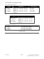
DIVISION 28 23 23 VDT/VDR1505WDM SERIES – FIBER OPTIC TRANSMITTER AND RECEIVER ENGINEERING SPECIFICATIONS to 95% (non-condensing). If product is installed in condensation conditions, unit shall have conformal coating applied to the printed circuit board. 1.08 WARRANTY A. Standard International Fiber Systems Comprehensive Lifetime Warranty: IFS warrants the product to be free of factory defects under manufacture’s Lifetime Warranty as submitted under article 1.05 (E) PART 2 - PRODUCTS 2.01 MANUFACTURER A. Acceptable Manufacturer: International Fiber Systems, Inc.; 16 Commerce Road, Newtown, CT 06470 USA; Telephone: 203-426-1180; Fax 203-426-3326; Email: [email protected]; Internet: www.ifs.com B. Substitutions: Not Permitted C. All fiber optic modules shall be supplied from a single manufacturer. 2.02 MANUFACTURED UNITS A. Model Number Descriptions: Reference Table A: Product Number Descriptions B. Model Compatibility Chart: Reference Table B: Product Compatibility Chart 2.03 GENERAL SPECIFICATIONS A. The Digital Video Transmitter/Receiver and return data transmitter system shall be an IFS VDT/VDR1505WDM series module. The module shall be capable of transmitting full color video in real time in NTSC, PAL or SECAM formats. The module shall transmit and receive the data in an up – the – coax fashion. The module shall be transparent to data protocols used by various manufactures, providing for universal compatibility should future system expansion or changes be required. The module shall be compatible with Pelco Coaxatron, Vicon Vicoax, Panasonic Proteus, Bosch BiLinx and Videolarm. The module shall have AGC (automatic gain control) circuitry to ease operation. The module shall require no in-field electrical or optical adjustments or in-line attenuators to ease installation. The module shall transmit the video and data signals using digital pulsing of the optical signal. The video and data is transmitted simultaneously on one fiber, the module shall utilize an integrated WDM for increased stability and reliability of system performance. The module shall provide power or power and AGC (automatic gain control) detect status indicating LED’s for monitoring proper system operation. The modules shall provide automatic re-settable solid-state current limiters and independent voltage regulators on each module to reduce the chance of a single point failure of the system. The module shall be hot swappable in a rack mount system to reduce complete system shut down during maintenance or repair. The module shall have an MTBF of PART 1 - GENERAL 1.01 SUMMARY A. Fiber Optic Digital Video Transmitter and Receiver with Return Data 1.02 SECTION INCLUDES A. VDT/VDR1505WDM Series Digital Video with Return Data – Standalone B. VDT/VDR1505WDM-R3 Series Digital Video with Return Data - Rack Mount 1.03 REFERENCES A. Underwriters Laboratory (UL) B. Underwriters Laboratory Canada (ULC) C. European Union Compliance (CE) 1.04 SYSTEM DESCRIPTION A. Performance Requirements: Provide a Digital Video Transmitter /Receiver and integrated data transmitter system that transmits One-way video and return data. 1. The system shall utilize integrated WDM optics operating at 1300/1550nm capable of simultaneous video and data transmission on one multimode optical fiber (VDT/VDR1505WDM), or one singlemode optical fiber (VDT/VDR1535WDM). 1.05 SUBMITTALS A. Product Data: Manufacturer’s printed product data sheet for each type of Transmitter/Receiver specified. B. Detail Drawings: Electrical and optical connect drawings. Product mounting template. C. Manufacturer’s Installation and Operating Manual: Printed installation and operating information for each type of Transmitter/Receiver specified. D. Test Reports: Manufacturer’s Printed Test Report via a Tektronics VM700A Video Test Generator verifying product performance meets or exceeds the specified product performance referenced in Part 2. E. Warranty: Manufacturer’s Printed Warranty 1.06 DELIVERY, STORAGE AND HANDLING A. Deliver materials in unopened factory packaging with Manufacturer’s bar coding to the job site. B. Inspect product upon delivery to assure that specified products have been received. C. Store in original packaging in a climate controlled environment. Storage Temperature not to exceed: -40˚ C to +85˚ C 1.07 PROJECT/SITE CONDITIONS A. Temperature Requirements: Products shall operate in an environment with an ambient temperature range of –40˚ C to +74˚ C without the assistance of fan-forced cooling. B. Humidity Requirements: Products shall operate in an environment with relative humidity of 0% Project name/project number/date 00000 - 1 (Optional information, e.g., owner, A/E) Section Title >100,000 hours and operate in an environment of –40˚ C to +74˚ C and relative humidity between 0% to 95% (non-condensing). The module shall be UL and ULC listed and CE marked. The circuit board shall be UL 94 flame rated and meet all PCI standards. All PC boards shall be designated with part number, PC board number and show appropriate revision number. Housing shall be of all metal construction. All LED indicators and both electrical and mechanical connections shall be identified with silk-screened labels. The module shall have a lifetime warranty to reduce system life cycle cost in an event of a module failure. 2.04 VIDEO SPECIFICATIONS A. Input Video: 1 volt pk-pk (75 ohms) B. Bandwidth: 5 Hz – 10 MHz C. Differential Gain: < 1 %. D. Differential Phase: < 0.7 °. E. Tilt: <1% F. Signal/Noise Ratio: 67dB 2.05 DATA SPECIFICATIONS A. Pelco Coaxatron B. Panasonic Proteus C. Bosch Bi-Linx 2.06 OPTICAL SPECIFICATIONS A. IFS Model Number VDT/VDR1505WDM 1. Optical Fiber: 62.5/125 micron multimode 2. Number of Fibers Required: 1 3. Optical Wavelength: 1300nm/1550nm 4. WDM: Integrated WDM 5. Optical Emitter Type: VT 1300nm LASER VR 1550nm LASER 6. Transmitter Output Power: 25µw (-16 dB) 7. Optical Detector Type: VT 1550nm PIN VR 1300nm PIN 8. Receiver Sensitivity: 1µw (-30 dB) 9. Optical Power Budget: 15 dB 10. Optical Attenuation: No manual adjustments required B. IFS Model Number VDT/VDR1535WDM 1. Optical Fiber: 9/125 micron singlemode 2. Number of Fibers Required: 1 3. Optical Wavelength: 1300nm/1550nm 4. WDM: Integrated WDM 5. Optical Emitter Type: VT 1300nm LASER VR 1550nm LASER 6. Transmitter Output Power: 25µw (-16 dB) 7. Optical Detector Type: VT 1550nm PIN VR 1300nm PIN 8. Receiver Sensitivity: 1µw (-30 dB) 9. Optical Power Budget: 18 dB (@ 1300nm) 10. Optical Attenuation: No manual adjustments 2.07 STATUS INDICATORS A. Power: On/Red – Off/Off B. AGC (automatic gain control): AGC Active/Yellow – No AGC/Off 2.08 CONNECTORS A. Optical: ST B. Power: Terminal Block with Screw Clamps Section Title C. Video and Data: BNC (Gold Plated Center-PIN) 2.09 ELECTRICAL SPECIFICATIONS A. Power: VDT 24 VAC CT VDR 12 VDC B. Current Protection: Automatic re-settable solidstate current limiters C. Voltage Regulation: Solid-state, Independent on each board D. Circuit Board: UL 94 flame rated and meets all PCI standards. E. Rack mount Card: Shall be hot-swappable with IFS Model Number R3 (EIA 19” card cage) 2.10 MECHANICAL SPECIFICATIONS A. Surface Mount Dimensions: 7.1” x 4.9” x 1.0” (18.00 cm x 12.45 cm x 2.54 cm) B. Rack Mount Dimensions: 7.7” x 5.0” x 1.0” (19.56 cm x 12.70 cm x 2.54 cm) C. Number of Rack Slots: 1 D. Finish: Module shall be constructed of a metal enclosure with a powder coat finish model Number F63B12 with all connections and indicators silk-screened directly on unit. Rack mount units shall be constructed of anodized aluminum. E. Weight: <2.0 lbs./1.0kg 2.11 ENVIRONMENTAL SPECIFICATIONS A. MTBF: >100,000 Hours B. Operating Temp: –40˚ C to +74˚ C C. Storage Temp: -40˚ C to +85˚ C D. Relative Humidity: 0% to 95% (noncondensing). If product is installed under condensation conditions, unit shall have conformal coating applied to the printed circuit board. (Add –C to model number for conformal coated printed circuit board) 2.12 REGULATORY AGENCIES/APPROVALS AND LISTINGS A. Underwriters Laboratory (UL) Listing Number: I.T.E. 6D16 B. Underwriters Laboratory Canada (ULC) Listing Number: I.T.E. 6D16 C. UL 94-flame rated PCB board: 94VO D. CE European Union Compliance 2.13 ACCESSORIES A. Card Cage: IFS Model Number R3 (EIA 19” card cage) shall be available to house and power rack mount modules. B. Blank Panels: IFS Model Number R3-BP shall be available to cover unused rack slots. PART 3 - EXECUTION 3.01 EXAMINATION A. Inspect modules before installation. B. Modules shall be free of any cosmetic defects or damage. C. All optical connectors shall be covered with dust caps and remain on the module until installing cable connectors to module. D. Shipping box shall include the module, power supply and operations manual. 3.02 PREPARATION 00000 - 2 Project name/project number/date (Optional information, e.g., owner, A/E) A. Standalone Module (Surface Mount) 1. Shall be mounted on a properly prepared surface adequate for the size and weight of module. The placement of the unit shall allow provision for cable installation and maintenance as indicated on the approved detail drawings and in compliance with the IFS mounting template and installation manual. B. Rack Mount Module (19” Rack) 1. Shall be installed in the IFS Model Number R3 card cage. Ensure the card cage is installed in a standard EIA 19” (482.6 mm) rack or wall standoff bracket adequate for the size and weight of the card cage. The placement of the unit shall allow provision for cable installation and maintenance as indicated on the approved detail drawings and in compliance with the IFS installation manual. C. Optical Fibers 1. Caution: NEVER look into the end of an active optical fiber when using laser light output. Eye damage can occur. Wear eye protection when cleaving, terminating, and splicing fiber. 2. The number and type (multimode or singlemode) of optical fiber shall meet the requirements of the IFS model number in article 2.06 used in the installation. 3. All optical fiber cables shall be properly installed and terminated with the mating optical connectors as submitted in article 2.08 (A). 4. The optical link shall be tested with either a power meter, at a minimum, or OTDR to ensure the link budget (overall path loss) plus an added 3dB of optical safety margin does not exceed the optical power budget as submitted in article 2.06. Project name/project number/date (Optional information, e.g., owner, A/E) 5. All optical connectors on cable shall be cleaned in compliance to optical connector manufactures specifications and covered with dust caps until connection to the fiber optic module. 3.03 INSTALLATION A. General: Locate fiber optic modules as indicated on the approved detail drawings and install module in compliance with the IFS installation and operations manual. 3.04 TESTING A. Testing the Fiber Optic Video Link. 1. Verify that the coax and optic fibers are properly connected. 2. Make sure that power is applied to all fiber optic modules, camera, and video monitor or other equipment used in the system. 3. The AGC (automatic gain control) indicator LED should be lit confirming a presence of a video signal. 4. Successful video link operation should be visible at this point as witnessed by a good quality video picture on the monitor. B. Testing the Fiber Optic Data Link. 1. Verify that the optical fibers are properly connected. 2. Make sure that power is applied to all fiber optic modules, controllers, and receiver drivers or other equipment used in the system. 3. Successful data link operation should be confirmed at this point by using the controller to pan, tilt, and zoom the camera or communicate with other equipment. 3.05 CLEANING A. Follow all instructions for proper use of solvents and adhesives used for termination and splicing. B. At completion of the installation, dispose of all fiber scraps properly. 00000 - 3 Section Title MANUFACTURED UNITS REFERENCE TABLES Table A: Product Number Descriptions VDT1505WDM SERIES VDT1505WDM VDT1505WDM-R3 DESCRIPTION MAX. DISTANCE* MM Data – 1550 <> Video/Data – 1300, 1 Fiber 3 Miles (5KM) MM Data – 1550 <> Video / Data – 1300, 1 Fiber, 3 Miles (5KM) Rack Mount VDT1535WDM SM Data – 1550 <> Video / Data – 1300, 1 Fiber 15 Miles (25KM) VDT1535WDM-R3 SM Data – 1550 <> Video / Data – 1300, 1 Fiber, 15 Miles (25KM) Rack Mount * Maximum distance is limited to optical loss of the fiber and any additional loss by connectors, splices and patch panels. VDR1505WDM SERIES VDR1505WDM VDR1505WDM-R3 VDR1535WDM VDR1535WDM-R3 DESCRIPTION MM Data – 1550 <> Video/Data – 1300, 1 Fiber MM Data – 1550 <> Video / Data – 1300, 1 Fiber, Rack Mount SM Data – 1550 <> Video / Data – 1300, 1 Fiber SM Data – 1550 <> Video / Data – 1300, 1 Fiber, Rack Mount Table B: Product Compatibility Chart TRANSMITTER VDT1505WDM VDT1505WDM-R3 VDT1535WDM VDT1535WDM-R3 COMPATIBLE RECEIVER VDR1505WDM, VDR1505WDM-R3 VDR1505WDM, VDR1505WDM-R3 VDR1535WDM, VDR1535WDM-R3 VDR1535WDM, VDR1535WDM-R3 END OF SECTION Section Title 00000 - 4 Project name/project number/date (Optional information, e.g., owner, A/E)