1
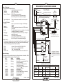
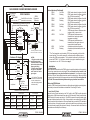
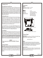
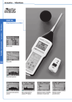
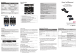
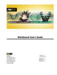
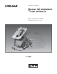
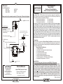
8
Reference:
Ford SEIC Bulletins:
2011 Gas
2011 Diesel
2008 - 2010
InPO
WER
the systems people
Q-173-R2
Q180-A
Q-172
OWNERS MANUAL
Model ETM51
Electronic Throttle Module
2005+ Ford Gas & Diesel Engines
A. Introduction
Relay circuit for fully automatic reset for 2011 and later F-Series Gas Engines
On/Off
Fused +12 Volts
30
85
87
86
To Ford SEIC wires:
PTO RS2 (PTO_ENGAGE)
(Blu/Orange)
(Some early 2011 builds
used Blue/Gray)
View looking into OBD-II connector
located on lower dash on drivers side.
Shield
CANH (Yellow)
PTO_RELAY (Blue/White)
1 2 3 4 5 6 7 8
9 10 11 12 13 14 15 16
PTO RPM (Green)
CANL (Green)
B. Operation
PTO RS1 (PTO MODE)(YellowGreen)
Green
(Pin 14)
RPM3 RPM2 RPM1
PTO
+12V
RPM
REF
Ground
GND
InPower
ETM51
RPM1
Shield
(Pin 5)
Yellow
(Pin 6)
CANL
CANH
VRPM
RPM1
RPM2
RPM3
VRPM
APDL
BUS
GEAR
PK BRK
SR BRK
VSPD
RPM2
RPM3
Green
The InPower Model ETM51 electronic throttle module is designed for installation in
2005+ Ford trucks and vans that are equipped with the Ford Stationary Elevated Idle
Control (SEIC) and have one the following engines:
6.4 Liter Power Stroke Diesel
6.8 Liter Triton Gas
6.0 Liter Power Stroke Diesel
5.4 Liter Triton Gas
6.7 Liter Power Stroke Diesel
6.2 Liter Triton Gas
Four modes of fast idle control are provided, including three fast idle preset speeds
(user adjustable), and a variable speed input (remote variable resistor). The ETM51
electronic throttle installation requires customer supplied control wiring to select the
required mode of operation and to connect to the Ford SEIC (Stationary Elevated Idle
Control) wiring (Ford provides blunt-cut wires). This wiring connects to the ETM51
module via 0.25 inch Faston (blade) terminals. The ETM51 system is supplied with a
three-foot shielded data cable. This cable contains a 16-pin connector at one end and
two 0.25 inch Faston terminals at the other end. The Faston terminals will connect at the
ETM51 module and the 16-pin connector plug will attach to the vehicle’s OBDII (On
Board Diagnostic) data link connector (DLC). The DLC is usually located at the lower
part of the dash on the driver’s side.
Yellow
When the vehicle is parked and Chassis Ready Conditions are satisfied the engine
speed may be controlled by one of the four available modes (three preset speeds or the
variable rpm). The preset speed may be adjusted by three calibration potentiometers on
the top of the ETM51 module.
Chassis Ready Conditions are:
1. Parking brake is set
2. Gear shift in “Park” (automatic transmission only)
3. Foot is off service brake
4. Foot is off the accelerator pedal
5. Vehicle is stationary (no speed)
6. Engine is started and idling below 900 rpm
7. Coolant temperature >140° F (Gas), 120° F (Diesel)
8. Transmission temperature 20° F to 240° F
RPM 1
Fused +12 Volts
Owners Manual
InPOWER LLC
3555 Africa Road
Galena, Ohio 43021 U.S.A
(740)548-0965
www.InPowerDirect.com
Model ETM51 Electronic Throttle
Document: OM-54 Version H
Date: January 24, 2012
© Copyright 2012 InPower LLC
Important Notes:
1. Do not connect any other 12 volt source to the ETM51’s PTO terminal!
2. If the engine is in the fast idle mode and one of the Chassis Ready Conditions
inputs changes state, the engine will return to normal (low) idle speed. If the
input then returns to satisfy the Chassis Ready Conditions while the fast idle
mode is still selected, the diesel engine will automatically return to fast idle after
about three seconds. However, the gas engines and the 2011 and later diesel
engine will not automatically return to the fast idle speed. To reset the Ford SEIC
so that it will return to the fast idle, you must turn off the Fast Idle On/Off switch,
then turn it back on. With the ETM51 Rev. H and later software the reset can be
accomplished automatically on gas engine systems with the addition of a relay
circuit (see page 8).
ETM51 OM-54H
2
7
Modes Of Operation:
1. Three Preset RPM High Idle Modes:
Function:
Increase idle to a preset rpm value
Terminals:
RPM1, RPM2, RPM3
Activation:
Apply +12 V to terminal
Range of Calibration: 900 to 2250 rpm (gas engines)
1200 to 2300 rpm (2005 - 2010 diesel engine)
900 to 3000 rpm (2011 and later diesel engine)
Enable:
Disengage:
RPM Range:
PTO
GEAR
On Solid
GEAR
Flashing
PK BRK
PK BRK
SR BRK
SR BRK
VSPEED
VSPEED
On Solid
Flashing
On Solid
Flashing
On Solid
Flashing
Indication
Module ON and functioning
Module ON, but a problem with CAN
bus communications
Transmission in PARK position or
Clutch Pedal released
Transmission not in PARK position or
Clutch Pedal activated
Park Brake set
Park Brake not set
Service Brake at rest (not activated)
Service Brake activated
Vehicle stationary
Vehicle moving
ETM51 OM-54H
Ground
GND
InPower
ETM51
REF
RPM1
CANL
CANH
Shield
CANH (Yellow)
RPM2
RPM3
Yellow
Green
VRPM
1 2 3 4 5 6 7 8
9 10 11 12 13 14 15 16
CANL (Green)
View looking into OBD-II connector
located on lower dash on drivers side.
Customer To Supply
Fast Idle
RPM 1
On
RPM 2
*
Off
RPM 3
*
Status Indicators
A 10 segment LED provides status and problem detection information. Refer
to the following table for coding of these functions.
Status
On Solid
Flashing
Shield
(Pin 5)
Yellow
(Pin 6)
+12V
RPM
Highest - Will override RPM2, RPM3, VRPM
Second - Will override RPM3, VRPM
Third - Will override VRPM
Lowest - Will only activate when other modes are off
LED
BUSS
BUSS
Green
(Pin 14)
RPM3 RPM2 RPM1
3. Mode Priorities:
A mode priority selection scheme is provided that will eliminate conflicts if more
than one mode is selected at a time. In the case of one or more modes being
selected, the following priorities will be established:
RPM1
RPM2
RPM3
Variable RPM
WARNING! Do not connect any 12 volt
source to the PTO terminal wiring.
Three potentiometers accessible from the top of the
module
Varies rpm as a function of voltage on VRPM input
terminal
VRPM
10K Ohm potentiometer between the VRPM terminal
and ground
Turn potentiometer down to zero resistance, then slowly
increase until desired rpm is reached
Turn potentiometer down to zero and rpm will drop to
standard idle speed
900 to 2250 rpm (gas engines)
1200 to 2300 rpm (2005 - 2010 diesel engine)
900 to 3000 rpm (2011and later diesel engine)
OBD-II
Diagnostic
Connector
Ford SEIC Blunt-Cut Wires
(See table for wire colors)
RPM1
RPM2
RPM3
VRPM
APDL
Terminal:
Adjustment:
X X X
Ford Chassis
VSPD
2. Variable RPM Mode:
Function:
PTO
PTO RPM
PTO VREF
BUS
GEAR
PK BRK
SR BRK
Type of Adjustment:
DIESEL ENGINE CHASSIS WIRING DIAGRAM
Fuse
+12 V Ignition (This supply
must be from a circuit with
no other loads such as relays
that might generate electrical
noise)
RPM Control
*
10,000 Ohm
10-Turn
Chassis Ground
(Battery Neg.)
* Optional
FORD SEIC WIRE COLOR CHART
F-Series Diesel
Function
PTO
2005 - 2007
6.0 L
Orange
2008 - 2010
6.4 L
2011 and later
6.7 L
E-Series Diesel
2005 - 2008
6.0 L
2009
6.0 L
Yellow/Green
Yellow/Green
Purple/Lt. Blue
Yellow/Green
PTO RPM
Orange/Yellow
Green
Green
Orange/Yellow
Green
PTO VREF
Orange/Red
White/Brown
White/Brown
Orange/Red
White/Brown
ETM51 OM-54H
6
3
GAS ENGINE CHASSIS WIRING DIAGRAM
PTO ENGAGE
PTO RPM
PTO MODE
X X X
Status Indicators (Continued)
FORD CHASSIS
OBD-II
Diagnostic
Connector
Ford SEIC Blunt-Cut Wires
(See table for wire colors)
WARNING! Do not connect any 12 volt
source to the PTO terminal wiring.
Green
(Pin 14)
RPM3 RPM2 RPM1
PTO
+12V
RPM
REF
Shield
(Pin 5)
Yellow
(Pin 6)
Ground
GND
InPower
ETM51
RPM1
CANH
RPM1
RPM2
RPM3
VRPM
APDL
BUS
GEAR
PK BRK
SR BRK
VSPD
Yellow
Green
VRPM
Shield
CANH (Yellow)
1 2 3 4 5 6 7 8
9 10 11 12 13 14 15 16
CANL (Green)
View looking into OBD-II connector
located on lower dash on drivers side.
Customer To Supply
Fast Idle
RPM 1
*
On
*
RPM 2
*
RPM 3
*
RPM Control
Off
Fuse
10,000 Ohm
10-Turn
Chassis Ground
(Battery Neg.)
Optional
NOTES:
1. Engine must be running
and all Chassis Ready
Conditions must be correct
before closing this switch!
(Gas engines only.)
2. Refer to relay diagram
on page 8 for automatic
reset circuit for F-Series
gas engines.
+12 V Ignition (This supply
must be from a circuit with
no other loads such as
relays that might generate
electrical noise.)
FORD SEIC WIRE COLOR CHART
E-Series Gas
F-Series Gas
Function
PTO MODE
PTO RPM
2005 - 2007
5.4 L & 6.8 L
Orange
Orange/Yellow
PTO ENGAGE Orange/White
On Solid
Flashing
RPM2
RPM2
On Solid
Flashing
RPM3
RPM3
On Solid
Flashing
VRPM
Off
VRPM
On Solid
VRPM
Flashing
APDL
APDL
On Solid
Flashing
CANL
RPM2
RPM3
RPM1
RPM1
2008-2010
5.4 L & 6.8L
2011 and later
6.2 L & 6.8 L
2005 - 2008
5.4 L & 6.8L
2009 - 2012
5.4 L & 6.8 L
Yellow/Green
Yellow/Green
Orange
Yellow/Green
Green
Green
Orange/Yellow
Green
Blue/Green
Blue/Orange*
Orange/White
Blue/Green
RPM1 mode selected, engine at fast idle
RPM1 mode selected, engine not at fast
idle (PCM not responding*)
RPM2 mode selected, engine at fast idle
RPM2 mode selected, engine not at fast
idle (PCM not responding*)
RPM3 mode selected, engine at fast idle
RPM3 mode selected, engine not at fast
idle (PCM not responding*)
VRPM terminal at zero resistance value
(engine at idle) or open circuit
VRPM terminal increases above
threshold level and engine speed
increases accordingly.
VRPM terminal increases above
threshold level but engine does not
respond with elevated speed.
Accelerator pedal at rest position
Accelerator pedal actuated (not at rest
position)
* The Ford powertrain control module (PCM) is not responding to the fast idle
speed request. This could be caused by a chassis ready conditions issue or
some other PCM system problem. This could also be caused by the failure to
power the ETM51’s +12 volt input until after the engine is started and engine
temperature is over 140° F. See note on page 6.
C. Installation
1. Getting Started
The recommended location for the ETM51 system is under the dash due to the proximity
of the wiring connections and cable length. The unit should not be located in the
engine compartment, or any location that is not protected. You will need a crimping
tool for the 0.25 inch Faston (blade) terminals, and a wire stripping tool. Be sure to follow
the crimping tool instructions for the proper wire size and terminals. Do not lengthen the
DLC Cable. Disconnect the battery before making any electrical connections.
2. Mount the ETM51Module
Mount the ETM51 module under the dash on a flat surface using the two mounting holes.
Ensure that you have sufficient distance to install the 36 inch long DLC cable.
3. Install the DLC Cable
Connect the two Faston terminals on the DLC cable to the ETM51 module terminals
(Yellow wire to CANH terminal and Green wire to CANL terminal). Route the cable to the
OBDII Data Link Connector and plug it in. The OBDII connector is usually located on the
lower part of the dash on the driver’s side. Using a cable tie, secure the plug to the OBDII
connector so that it will not vibrate out. We recommend that you route the DLC cable back
across the bottom of the plug/connector, and loop the cable tie around the plug, socket
and cable, thereby keeping the cable out of the way. Also ensure that the entire cable is
routed and secured to keep it out of the way.
* Some early chassis builds had a Blue/Gray wire.
ETM51 OM-54H
ETM51 OM-54H
4
5
C. Installation (Cont’d):
E. Specifications
4. Wire the Mode Selection and SEIC Controls
This section describes the wiring necessary to connect the ETM51 electronic throttle to
the Ford SEIC blunt-cut wires and to the Mode Selection controls (“Customer to Supply”).
As the wiring is different for gas and diesel engine applications, refer the appropriate
wiring diagrams on page 6 and 7. You will also need to obtain a good quality chassis
ground (battery negative) and a +12 volt supply that is fed from the Ignition Switch. Note
that on gas engine installations, Ford requires this +12 volt supply to be “clean.”
That is, it should not have any other loads such as relays on the same circuit that
could generate electrical noise.
8 to 16 volts
30 mA
0.17 lbs
Faston 0.25 inch terminals
Cyolac thermoplastic (UL 94VO)
Epoxy potting compound,
resistant to most fuels, oils,
acids, and cleaning agents.
4.00
3.50
PTO
RPM
REF
RPM1
RPM2
RPM3
RPM1
RPM2
RPM3
VRPM
APDL
GND
+12V
CANL
Preset speed calibration
potentiometers (3 places)
RPM3 RPM2 RPM1
BUS
GEAR
PK BRK
SR BRK
VSPD
CANH
Note on Variable RPM Control - If you are using the Variable RPM mode you will need to
supply a 10,000 ohm variable resistor (potentiometer) between the VRPM terminal on the
ETM module and ground. We recommend a ten-turn potentiometer such as is available
from Williams Controls (www.wmco.com), or Digikey (www.digikey.com).
Mechanical
Weight:
Connections:
Case Material:
Encapsulation Material:
VRPM
4A. Idle Speed Mode Controls
First, determine the combination of fast idle speed modes that you will need (variable rpm
control and/or up to three fixed preset speeds). You will need a 10,000 Ohm
potentiometer for the variable rpm control, and a switch (or relay contact) for the fixed
speed presets (RPM1, RPM2 & RPM3). You will also need a Fast Idle On/Off switch.
Wire these devices as shown in the Wiring Diagram - Gas Engines (Page 6) and Wiring
Diagram - Diesel Engines (Page 7). You will need to obtain a good quality chassis ground
(battery negative) and a +12 volt fused supply fed from the Ignition Switch. Refer to the
Ford Body Builders Layout Book for location of these circuits.
Electrical
Input Voltage (+12V Terminal):
Input Current (+12V Terminal):
0.1875
2.05
1.025
0.25 Inch Faston Terminals
0.50
4B. Ford SEIC Wiring
Install wires between the ETM51 module and the Ford SEIC as shown in the wiring
diagrams on page 5 and 6. The Ford SEIC wires are blunt-cut, color coded wires located
above the parking brake pedal on the F-Series trucks. On E-Series vans they are located
in the engine compartment on the top, driver’s side of the firewall. Refer to Ford SEIC
documentation for more details. Note that the wiring is different for the gas and diesel
engines. Also, the gas engine application requires a “clean” +12 volt power source.
This must be a +12 volt circuit switched by the ignition switch that is isolated from
other circuits. That is, no other loads such as relays can be on the same circuit.
WARNING!
Do not connect any 12 volt source to the ETM51’s PTO terminal
wiring.
D. Setup and Calibration
The only calibration required is to select each of the three preset rpm modes (RPM1,
RPM2 & RPM3) and adjust the three respective calibration potentiometers on the top of
the ETM51 module to the desired speed (900 through 2,250 rpm on gas engines, 1200 to
2300 rpm on the 2005 - 2010 diesel engine and 900 to 3000 on the 2011 and later diesel
engine). Adjustments can be made with a 1/16” (1.6 mm) or smaller screw driver. Each
potentiometer is a ten turn device, with an increase or decrease of about 300 rpms per
complete turn.
ETM51 OM-54H
All dimensions in inches. Not to scale.
F. Customer Support
Technical Support
For product support, contact InPower at 740-548-0965 or 866-548-0965. Product
bulletins and owner’s manuals are available on our web site:
www.InPowerDirect.com.
Warranty
InPOWER LLC warrants its products to be free from defects in material and
workmanship under normal use, care and maintenance for a period of two (2) years
from the date of shipment. Please see www.inpowerdirect.com/warranty.htm for
specifics or call 866-548-0965 for a copy of our warranty policy.
Customer Evaluation
InPower wants to ensure total customer satisfaction. Please download a product
evaluation form at www.InPowerDirect.com/Customer_evaluation.htm or call us toll
free at 866-548-0965 to be sent a form by mail.
ETM51 OM-54H