1
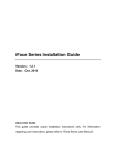
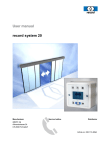
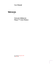
F7_F707_F708 Installation Instruction V1.0 F7_F707_F708 Access Control Terminal Installation Instructions Revised May 2008 About this Guide This guide provides installation instructions only. For information regarding actual operation and configuration of the F7_F707_F708 Time & Attendance and Access Control Terminal, refer to the user manual. -1- F7_F707_F708 Installation Instruction V1.0 Table of Contents Before Installation ................................................................................. 1 Front and Read Panel views ………………………………………….5 Optional 3rd Party Equipment………………………………………..6 1.0 Installation........................................................................................ 7 1.1 Attaching Mounting Plate……………………………………..7 1.2 Connecting Power Supply……………………………………. 9 1.3 Selecting Door Lock………………………………………… 10 1.4 Connecting an electric strike or magnetic lock……………... 11 1.5 Powering Door Lock………………………………………... 13 1.6 Connecting switches, door sensor, doorbell, etc……………..14 1.7 Connecting 3rd party door controller/panel…………………..16 1.8 Connecting network or computer…………………………….17 2.0 Testing……………………………………………………………..20 2.1 Run Auto Test………………………………………………...20 2.2 Test Fingerprint Enrollment………………………………….23 3.0 Fastening to mounting plate and wall…………………………..30 4.0 Miscellaneous……………………………………………………..31 5.0 Trouble-shooting………………………………………………...32 -2- F7_F707_F708 Installation Instruction V1.0 Before Installation 1. Prior to beginning installation, cut off all power to prevent personal injury and damage to the F7_F707_F708 and peripheral equipment. 2. Connect the ground wire first, in order to prevent electro-static damage to the F7_F707_F708. 3. Connect 12V DC power supply to the F7_F707_F708 last. If the F7_F707_F708 does not operate properly, always cut off power to it before examining/dismantling. Be advised that wiring the F7_F707_F708 while power is on may cause damage to the terminal. Possible resulting damage from not powering off the F7_F707_F708 prior to wiring is not covered by manufacturer’s warranty. 4. Mount the F7_F707_F708 at a comfortable height, typically between 4 and 5 feet from the ground. 5. After installation, remove protective film from the F7_F707_F708 display and fingerprint sensor. 6. To prevent being accidentally locked out while testing the exit-door button, keep a person on the inside of the door. 7. Run the auto-test function to confirm that installation is successful. -3- F7_F707_F708 Installation Instruction V1.0 8. In order to maximize the life of the F7_F707_F708, use the auto-sleep and wake up functions. 9. ONLY use a 12V DC 1.5Amp power supply for proper functioning of the F7_F707_F708 terminal. If the incorrect voltage is used, the F7_F707_F708 may keep rebooting or may not operate the electric door lock (if attached). 10. Improper wiring may cause the F7_F707_F708’s main circuit board and fingerprint sensor to burn out. Resulting damage from improper wiring is not covered under manufacturer’s warranty. 11. Only use supplied transformer and cord. Do not attempt extending the cord by cutting and splicing. 12. If using RS485 mode of communication, use only a ZK Software-supplied RS485 converters. Using a 3rd party RS485 converter may or may not work. If the RS485 cable length exceeds 200 feet, we recommend using a 120Ώ terminator. 13. Refer to the user handbook and operating instructions for further information. -4- F7_F707_F708 Installation Instruction V1.0 Front panel view; Rear panel view; -5- F7_F707_F708 Installation Instruction V1.0 Optional 3rd party equipment The following equipment is not provided by ZK Software, but often compliments a complete Access Control solution; Part Image Part Door Lock PC Exit Button Door sensor Alarm RS485/ RS232 converter Door Controller Network Cable -6- Image F7_F707_F708 Installation Instruction V1.0 1.0 Installation 1.1 Attach Mounting Plate 1. Take out the F7_F707_F708 fingerprint terminal and remove the screw (screwdriver supplied) which secures the F7_F707_F708 to its mounting plate; 2. Remove mounting plate by grasping the bottom edge and lifting it inward and upward. 3. Determine the position of mounting plate on the wall. We recommend about 4-5 feet from the ground so it is comfortably within reach of most of your users. -7- F7_F707_F708 Installation Instruction V1.0 4. After its position is determined, cut-out square-openings in the walls which correspond to the cut-outs in the F7_F707_F708’s mounting plate for wires to pass through; 5. Use 3 mounting screws (supplied) to affix the F7_F707_F708 mounting plate on the wall. 6. Then secure the F7_F707_F708 to the mounting plate. -8- F7_F707_F708 Installation Instruction V1.0 1.2 Connecting Power Supply F7_F707_F708 operates on 12V DC Power supply and connect the positive and GND as shown below. If you are connecting a magnetic lock or an electric strike to F7_F707_F708 than we recommend it should draw maximum current of 1A. If you need more power than please use an external power supply of higher current capacity. GND GND RS232 RXD +12V Power RS232 TXD Lock COM GND Lock NO RS485 A Lock NC RS485 B GND GND Alarm+ DATA0 Alarm— DATA1 Button +5V Output GND Door Sensor Bell+ GND Bell— -9- —12V DC +Power supply adapter F7_F707_F708 Installation Instruction V1.0 1.3 Selecting door lock For glass doors which swing both in and out, we recommend the use of electro-magnetic door strikes (aka “mag locks”). For 1-way opening non-glass doors we recommend the use of electric door strikes, instead. While both locks are equally secure, the mag lock is considered safer than the electric strike, especially during power interruptions. During a power failure caused by fire or other safety threats, the mag lock will “fail open” and allow people to exit a room/building unhampered. Conversely, the electric strike “fails closed”. With loss of power you can still exit a door secured by an electric door strike. But you’ll need a mechanical device (i.e. door handle or exit bar) to free the door during power interruptions. ZK Software is not responsible for any personal injury or damage caused by power failure. - 10 - F7_F707_F708 Installation Instruction V1.0 1.4 Connecting an electric strike or magnetic lock F7_F707_F708 has NO and NC closed contacts for controlling the locks. Since there are many different type s of locks available we recommend to connect these locks as per the recommendation of the manufacturers. Ensure that proper voltages are applied to the lock terminals and check on the current ratings of the locks. GND GND RS232 R×D +12V Power RS232 T×D Lock COM GND Lock NO RS485 A Lock NC RS485 B GND GND Alarm+ DATA0 Alarm- DATA1 + 12V Power supply adapter + Lock Button +5V Output GND Door Sensor Bell+ GND Bell- - 11 - F7_F707_F708 Installation Instruction V1.0 + 12V GND GND RS232 R×D +12V Power RS232 T×D Lock COM GND Lock NO RS485 A Lock NC RS485 B GND GND Alarm+ DATA0 Alarm- DATA1 GND Door Sensor Bell+ GND Bell- GND GND RS232 R×D +12V Power RS232 T×D Lock COM GND Lock NO RS485 A Lock NC Power supply adapter + Lock + 12V Power supply adapter Lock Power + GND GND Alarm+ DATA0 Alarm- DATA1 + 12V Button +5V Output RS485 B Power supply adapter + Lock Button +5V Output GND Door Sensor Bell+ GND Bell- Lock control relay - 12 - F7_F707_F708 Installation Instruction V1.0 1.5 Powering Door Lock The F7_F707_F708 can supply power directly to a door lock. However, in the following three scenarios, it is recommended that the door lock has an independent power source, and is NOT powered by the F7_F707_F708; • If the door lock voltage is not 12V DC then provide separate power to the door lock. • If the door lock runs on 12V DC, but requires more than 1A (amp), then provide separate power to the door lock. If the distance between the F7_F707_F708 and door lock is greater than 15 feet, then provide separate power to the door - 13 - F7_F707_F708 Installation Instruction V1.0 1.6 Connecting switches, door sensor, doorbell, etc. You can connect the exit switch as shown below. This is mainly used for receptionists to open the door for the visitors. The door sensor switch is used to trigger the alarm if the door is kept open for more than specified time. Furthermore, F7_F707_F708 will also send an alert signal if the door is not closed within the specified time. You can connect a doorbell to the F7_F707_F708 as shown below. Visitors can hit this button which will trigger the door bell inside the door. GND GND +12V Power RS232 T×D Lock COM GND Lock NO RS485 A Lock NC RS485 B GND GND Alarm+ DATA0 Alarm- DATA1 + Siren RS232 R×D Button +5V Output GND Door Sensor Bell+ GND Bell- Door Sensor Siren + Power supply - 14 - Exit Switch Doorbell F7_F707_F708 Installation Instruction V1.0 1.7 Connecting 3rd party door controller/panel The F7_F707_F708 provides standard Wiegand 26-bit output, which can be connected to most 3rd party access control panels. The F7_F707_F708 connects to the panel just like any card-reader or keypad. The distance from the controller to the F7_F707_F708 cannot be more than 200 feet. If the Wiegand signal must be transferred much further, or if electro-magnetic interference exists, utilize a Wiegand signal amplifier. Use the following connections; GND Access Controller GND RS232 R×D +12V Power RS232 T×D Lock COM GND Lock NO RS485 A Lock NC RS485 B GND GND GND Alarm+ DATA0 DATA0 Alarm- DATA1 DATA1 +12V +5V Output GND Door Sensor Bell+ GND Bell- - 15 - Button F7_F707_F708 Installation Instruction V1.0 1.8 Connecting network or computer F7_F707_F708 offers RS232 and RS485 interface, or Ethernet connectivity to connect with a computer network. Ethernet connection Option 1: Direct connection to PC via cross-over cable; Option 2: Indirect connection to PC via network router; - 16 - F7_F707_F708 Installation Instruction V1.0 NIC P C R S 2 3 2 Ethernet GND GND 1 CD 2 RXD RS232 RXD +12V Power 3 TXD RS232 TXD Lock COM 4 DTR GND Lock NO 5 GND RS485 A Lock NC 6 DSR RS485 B GND 7 RTS GND Alarm+ 8 CTS DATA0 Alarm- 9 RI DATA1 Button F7ÓëPC¿ÉÒÔ Í¨ ¹ý RS232»òEthernet £¨ ¿ÉÑ¡£©Ïà Á¬½Ó - 17 - +5V Output GND Door Sensor Bell+ GND Bell- F7_F707_F708 Installation Instruction V1.0 RS485 connection RS-485 systems using a bus structure configuration connect the driver to the receiver. The transmission line is made by a group of twisted-pair cables. Each cable has a pair of conductors consisting of inverted and non-inverted signal lines. The inverted line is generally designated by the letter "A" or "-", with the non-inverted line designated as "B" or "+". In order to eliminate or reduce “noise”, traditional RS485 networks require a 12Ω terminal resistor to be installed at the end of the bus cables based on the physical layout of the twisted-pair cables. In the normal condition the resistor is not installed, only if the bus is extended over 125 feet, the termination must be connected with a terminal resistor. - 18 - F7_F707_F708 Installation Instruction V1.0 2.0 Test and examine after installation With power on, test for the following: 9 The green LED lights up after power up. 9 2.1 Run Auto-test; Press the M (Menu) key on the F7. - 19 - F7_F707_F708 Installation Instruction V1.0 Scroll with the ▲/▼ keys and place the cursor ( ) alongside Options. Menu ▼ User Manage ► Options Press the OK key. The Options Menu will appear; Options ▲ ▼ Log Opt Access Options ► Auto Test Scroll with the ▲/▼ keys and place the cursor ( ) alongside Auto Test. - 20 - F7_F707_F708 Installation Instruction V1.0 Press the OK key. The following screen appears; AutoTest ▼ ► Run ALL Test LCD Test Voice Test FR Reader Key test RTC Test Scroll with the ▲/▼ keys and place the cursor ( ) alongside the feature you’d like to test and press the OK key. When finished testing, continue pressing the C (Cancel/ESC) key repeatedly until you return to the Start-Up window. Welcome Check-In HH:MM MM/DD/YY DAY Note: The actual current date/time will appear. - 21 - F7_F707_F708 Installation Instruction V1.0 9 2.2 Test Fingerprint Enrollment; Press the M (Menu) key on the F7. Scroll with the ▲/▼ keys and place the cursor ( ) alongside User Manage Menu ▼ ►User Manage Options - 22 - F7_F707_F708 Installation Instruction V1.0 Press the OK key. Scroll with the ▲/▼ keys and place the cursor ( ) alongside Enroll User. User Manage ►Enroll User Enroll Admin ▼ Press the OK key. Scroll with the ▲/▼ keys and place the cursor ( ) alongside Enroll FP. Enroll User ►Enroll FP Enroll Pwd FP & Pwd ▼ - 23 - F7_F707_F708 Installation Instruction V1.0 Press the OK key. The F7 will prompt you; Enroll FP New Enroll? ESC OK Press OK. Enroll FP New Enroll? ESC OK Since we are enrolling a New User, press OK. The F7 will then prompt you with the next available User ID; New Enroll UserID 00001-0 ESC OK In this example, no user has yet been enrolled on the F7. next available User ID# is 00001. - 24 - So the F7_F707_F708 Installation Instruction V1.0 Press the OK key to accept 00001, or manually key in a different number if desired. The F7 will then prompt; New Enroll 00001-0 Place Finger . . . ESC/Exit - 25 - F7_F707_F708 Installation Instruction V1.0 Remember the rules for proper finger placement; The user’s finger should completely cover the sensor. The finger should be placed flat and in the center of the sensor. The finger should cover at least 80% of the sensor as shown below: The finger should NOT be placed in the following positions: - 26 - F7_F707_F708 Installation Instruction V1.0 Place your finger on the sensor for a full 2 seconds. After the F7 scans your fingerprint successfully, it will “beep” and then prompt you briefly with; New Enroll 00001-1 Remove Finger ESC/Exit Then you’ll be prompted; New Enroll 00001-1 Second Press ESC/Exit - 27 - F7_F707_F708 Installation Instruction V1.0 Remove your finger, and then place your finger on the sensor a 2nd time. Again, you’ll be prompted briefly; New Enroll 00001-1 Remove Finger ESC/Exit Remove your finger, and then place your finger on the sensor a 3rd and final time. You’ll then be prompted; New Enroll 00001-0 ESC OK (Save) Press the OK key to accept the newly enrolled finger. The F7 will then prompt you with; New Enroll Continue? ESC OK - 28 - F7_F707_F708 Installation Instruction V1.0 UserID 0001 has now been successfully enrolled with one fingerprint. If you wish to continue enrolling additional users, press the OK key and follow the same procedures. If you’re finished enrolling additional users, press the C (ESC/cancel) key repeatedly, until you return the Start-Up window; Welcome Check-In HH:MM MM/DD/YY DAY Note: The actual current date/time will appear. Test the newly enrolled fingerprint by having UserID 00001 place his/her finger on the sensor. If successful, the F7 will respond with an audible “Thank you”, and the screen will display; Verify Pin: 00001 Verified. - 29 - F7_F707_F708 Installation Instruction V1.0 3.0 Fasten F7_F707_F708 to mounting plate/wall 9 Confirm all connecting wires are correct and securely fastened. 9 Properly align the rear metal-plate of the F7_F707_F708 to the mounting plate and then push up on it. Then push the F7_F707_F708 backwards. The F7_F707_F708 is now securely affixed to the mounting plate and wall. 9 Tighten screw on underside of F7_F707_F708. - 30 - F7_F707_F708 Installation Instruction V1.0 4.0 Miscellaneous 4.1 Reset IMPORTANT NOTE Resetting the F7_F707_F708 does NOT erase any stored data (i.e. templates, transactions, settings). This information will be available as soon as power is restored. To reset the F7_F707_F708 use a small tool (e.g., pin or paperclip) to push in the reset button (labelled “reset”) located on the underside of the F7_F707_F708 (see figure below). 4.2 Tamper-proof button When the F7_F707_F708 detects it is being “tampered” with, it will send an alarm signal. - 31 - Appendix 5.0 Trouble shooting Trouble Cause & Fix Power LED is off Cause : No power or lack of voltage Fix: Check and examine power and ground connections. Also ensure 12V DC power. F7_F707_F708 is unable to connect with PC Cause: Connection may be loose. Fix: Check that the RS232/RS485 or Ethernet connections are secure. Also make sure network/firewall settings are not blocking communication to the F7_F707_F708 LCD displays “Please try again”. Cause: The F7_F707_F708’s fingerprint sensor may have accumulated excess dirt or scratches over a period of time. This message indicates the sensor is unable to obtain a clear image of the fingerprint. Other possible cause may be fingerprint sensor cable has loosened from circuit board. Fix: Try using cellophane tape to remove dirt. Sensor may also need to be repaired/replaced. F7_F707_F708 starts up, but cannot enter menu system Cause: Fingerprint sensor cable is loose. Fingerprint sensor is broken. Circuit board is broken. Fix: Remove and plug back in Fingerprint sensor cable. - 32 - F7_F707_F708 Installation Instruction V1.0 Time continually displays “00:00” after restarting Cause: The clock battery is drained. Fix: Replace battery. The fingerprint sensor light is off Cause: Fingerprint sensor or flat connection cable is loose or broken. Fix: Unplug the cable from the fingerprint sensor and plug it back in again. Pressing buttons no longer makes sound. Cause: Trouble in the buzzer, loudspeaker or circuit. Fix: Need to replace the buzzer and loudspeaker. Some users’ fingerprints sometimes can’t be verified. Cause: The fingerprint quality is poor. Fix: If repeated attempts with the same finger fail, try using a different finger when enrolling. Also reduce fingerprint “threshold” setting. If user’s fingerprints completely unreadable, assign them a PIN number, instead. - 33 -