1
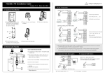
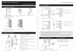
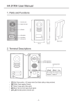
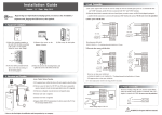
F10 Installation Guide F10 Installation GuideV2.2 Contents 1 Before Installing ...................................................................................1 1.1 Notice about installing...............................................................1 1.2 F10 Description .........................................................................3 2.System Configuration ........................................................................5 2.1 Standard connection illustration ................................................5 3.Installation .........................................................................................7 3.1Install backpanel........................................................................7 3.2 Connect with Peripheral Equipment ..........................................8 3.2.1 Connect to the Access Controller....................................9 3.2.2 Connect to Alarm.......................................................... 11 3.2.3 External Reader.............................................................13 3.2.4 RS485 connection .........................................................14 3.2.5 Complementary communications .................................15 3.2.6 power connections ........................................................16 3.3 fixed fingerprint machine ........................................................17 4. Others.................................................................................................18 4.1 Reset ........................................................................................18 4.2 Antidismantle button ..............................................................18 4.3 Builtin EM card reader (Optional) .........................................19 4.4 Builtin MIFARE card reader (Optional).................................19 5. Trouble shooting ................................................................................20 F10 Installation GuideV2.2 1 Before Installing 1.1 Notice about installing Access Control Station is a massproduced product. It strictly tested comply with the standard of China, U.S.A, and EU. This file contains important information. It is better for you to read it carefully prior to use. If you ignore it, the incorrect installation may cause the unit damage. Although we could do our best to offer you service, the neglect to the file could cause unwanted cost for you. 1. Before installation, please make sure the power is cut off, because it is very dangerous if the power is on. The short circuit of power cable may cause the core parts damage. 2. All exposed part of connection wire end cannot be exceeded 5mm to prevent the bared wire accidental connection which leads to machine break down. And also suggest using different color cable to connect. 3. In the place where the static is strong or in winter, please connect the grounding firstly, in order to prevent the instant mass static damage the machine. 4. Connect power supply with device in the last for the wiring connection. If you find any unusual thing occur, please firstly cut off the power, then go to examine. Keep in mind: wiring operation under power on will lead to machine sudden damage; we are not liable for damages 1 System Configure and trouble due to such operation. 5. The height to mount device is about 1.41.5 meter 6. After installation, please take off protection film on the fingerprint sensor to get best recognize result. 7. After installation finish, when go to test the exitdoor button, please keep a personal in the outside, because sometimes the accidental issue can bring on you are not able to go outside. 8.it is good a idea to use more than 12 V/1.5A independent DC power supply with this equipment and the controller or to reduce the electric locking interference, current ripple wave is less than 150 mV 9. When the system power supply from Access Controllers, should pay attention to the drive output capability of Access Controllers , Access Controller should be able to provide more than 500 mA current. 10.when hook up the Fingerprint reader network with the cable, 8shielding cable (RVVP 8X0.3MM2) is recommended to reduce the interference in the course of transmission, please read and always follow "Quick connect Guide" closely. Because the wrong wiring will cause the core block and sensor to burn out, insult in device to break down, at this cause ZK Software is not liable for any damages and trouble. 11. +12 V DC power supply cable by twocore power cord (RVV 2X2.5MM2), If the space between power adapters and device is too long, please do not use the twistedpair or other type ferrules for the power wire. When the power wire is selected, you should pay attenuation for voltage, which has passed long distance transfer. 2 F10 Installation GuideV2.2 12. Please use specialized RS485 cable,the internationally popular RVVP (shielded twisted pair)is recommended, Model RVVP 2x0.51.5mm2 (two core shielded twisted pair) and the RS232/485 converter with power to hookup the network, the bus structure apply to connect with each device. When a long cable is used to transfer signal, it is need to connect a matching resistance to receiver, and its value is 120Ώ. 13. Signal cable (such as RS485 cable) and highpower electricity cable do not (such as AC electric locking cable)place in parallel, not put in the same pipe Other more details items; please see also the user manual, the operating instructions and the appendix and so on. 1.2 F10 Description Pass/Fail Indicator & Activate Button: The indicator glow green which the flash interval is 1sec. in normal ready working state, and constantly glow green for 3 sec as the identification is positive, if the authentications fail it will constantly glow red light for 3 sec. When the sliding ID card or Mifare Card nearby RF sense area of the reader, if the card to be verified is valid, the indicator displays rapidly green flash 3 System Configure it interval time is 1 sec. press this button to activate the reader while it in normal working state, and wait for 3 sec. switch the reader into idle state. Fingerprint Sensor:Enroll or match fingerprint Power Indicator:It constantly glow green in the normal supply or idle state. 4 F10 Installation GuideV2.2 2.System Configuration 2.1 Standard connection illustration There are two ways, RS 485, Ethernet, to create network for F10, (see standard connection illustration). [RS485 network]: Set up network using 9600 baud rate. Only increase this data rate after the system is operating properly at 9600. 5 System Configure 6 F10 Installation GuideV2.2 3.Installation 3.1Install backpanel This product is designed for indoor installation, if it has to be installed it outdoor , please place the equipment in proper surroundings, you must beware of not exposing it to water or harsh condition , we remind to cover up the cable into the wall, if it isn’t capable to do, you must obtain the user’s permission before to install. Locate a comfortable height for finger place, firstly use the screwdriver along with the unit to turn off the screw in the bottom of the unit, and take away mounting plate, there are four fixhole in the mounting plate (see right illustration a, b, c, d), keep secure it on the wall using supplied screw, and fix the F10 reader body on the mounting plate. please strictly complied with the wire definition and colour, after finish the hookup, cut the expose part of the unwanted wire, especially red/white wire, and use the insulating tape to wrap it, because the red/white wire provide a output 12VDC voltage, when there is no external reader, No mater what, you must cut this wire and wrap it to keep away short circuit, You must ensure that hookup is correct follow the above table before power up and use. 7 Installation 3.2 Connect with Peripheral Equipment To help avoid possible damage serious damage to equipment , before connecting or disconnecting Peripheral Equipment, should ensure disconnect power from system by unplugging power cable,. Please observe and follow the guidecable to connect the external equipment. u Access Controller u An external card reader u Alarm u various network 8 F10 Installation GuideV2.2 u supporting auxiliary communication interface u Power supply 3.2.1 Connect to the Access Controller F10 as a fingerprint reader, until it connect with the access controller, unable to work alone, only serve as a fingerprint identification front end for system, and provide the controller with a standard or selfdefine Wiegand signal, such as other Proxy Card Reader adopt the standard signal (D0,D1,GND) connection method.(see standard connection illustration). These extension wire, LED Red, LED Green, Beep Out are used to get 9 Installation signal from the Access Controller. Depending on the Access controller setting to control the red /green Indicator, beep, which produce the corresponding active, for linking way, please refer to the reader connect with alarm Notice : Whatever the power of F10 supply by the access controller, or doesn’t it, the two equipment’s GND must be in common connection, Do not replace Weigand signal power GND with GND of powe, to ensure transfer the wiegand signal steady. please separately plot wiring T HD T IW T SD SS WD0 T DW WD1 SS Specifications: TDW pulse 100 um TIW cycle 1 mm Output drive capability 200mA 10 F10 Installation GuideV2.2 Definition terminal connection (7 PIN Cable) Number of terminal Functional 1 GND Ground 2 WD0 output signal wiegand data 0 3 WD1 output signal wiegand data 1 4 Spare 5 Spare 6 Spare 7 ALM alarm signal 3.2.2 Connect to Alarm F10 can connect a signal (alarm) to system, which mainly use to remind 11 Installation that the F10 has been dismantled ,no matter what condition, when it is removed F10 will trigger alarm output (brown wire) in the power on state, in normal condition, the wire doesn’t send any signal., F10 will link GND through the wire if the system be trigger, follow this principle we can achieve the remind function of dismantled alarm, connect the cathode of alarm power to alarm output( brown wire), the positive of alarm power link to the positive of F10 power ( see right Figure), F10 alarm output only support 12VDC alarm. Notice: There is a button to anti dismantle in the bottom of F10, realize function is to utilize the cylinder on the mounting plate to keep press the button Alarm Alarm connection 12 F10 Installation GuideV2.2 3.2.3 External Reader F10 utilize the function of wiegand input to support a external reader, at the same time F10 connect external reader via standard way, and the pin of reader (D0,D1,12V ) according to the pin of F10( Wiegand In D0, Wiegand In D1,GND,12VOUT) one by one to connect(see standard connection Illustration) Special Notice: when there is a Mifare module in the F10, the Wiegand input is invalid, if there is no external reader; don’t need to do this connection. Definition terminal connection(3 PIN) Number of terminal Function 1 GND Ground 2 IWD1 Receive wiegand signal data 1 3 IWD0 Receive wiegand signal data 0 13 Installation 3.2.4 RS485 connection RS485 systems using a bus structure configuration connect the driver to the receiver. The transmission cable is made by a group of pairtwisted cable. Each transmitted signal has a pair of conductors consisting of inverted and noninverted signal Cable. The inverted cable is generally indicated by the index "A" or "", with the noninverted cable designated as "B" or "+". The receiver simply evaluates the difference between the two Cable, so that common mode noise on the transmission cable will not result in a falsifying of the actual signal, however, on the cable may be produced a difference mode disturbing. In order to eliminate this disturbance, traditional RS485 networks require a 12Ω terminal resistor to be installed at the end of the bus cables based on the physical layout of the pairtwisted cables. In the normal condition the resistor is not installed, only if the bus is extended to over 100 meters, the termination must be connected with a terminal resistor. The define of terminal connection(5 PIN) Terminal Function 485A RS485 communication + 485B RS485 communication GND Ground Spare Spare 14 F10 Installation GuideV2.2 3.2.5 Complementary communications 8PIN cable provides Ethernet and RS232 connection, connection method shown above. Special Note: there is a assisted communication interface at the device bottom, that do not need to remove the machines establish a connection 15 Installation through cable, so when the official use, in any case must be set up communications password (that is, passwords for equipment and software communications, Software to set your own) The define of terminal connection (5 PIN) Number of terminal Functional TXO RJ451 TXO+ RJ452 RXI+ RJ453 RXD TXD of RS232 GND GND of RS232 RXI RJ454 TXD RS232 的 RXD Spare 3.2.6 power connections F10 power supply is 12 VDC, standby current about 50 mA, operating current of about 300 mA, please use only approved the power adapter, the power adapter must be rated for the product and for the voltage and current marked on the product’s electrical rating, otherwise it will cause serious damage. (See standard connecting figure). Power requirements: DC 12V ( / + 2V) 1A. Note: F10 directly power on through the power supply of the access controller, can also be an external sources of power. The define of terminal connection Terminal Functional GND Cathode +12V Positive DC +12V 16 F10 Installation GuideV2.2 3.3 fixed fingerprint machine After be sure all cable are inserted correctly into, fix installed backplane, and mount F10 on the backplane. Note: Please strictly in accordance with the definition and color to connect, and connect completed, All exposed part of connection wire end cannot be exceeded 5mm to prevent the bared wire accidental connection which leads to machine break down. in particular the red cable, as a 12 V output voltage, when there is no an external card reader, in any case ensure to cut this cable and use the insulation adhesive plaster to dress it, so as to avoid shortcircuit. 17 Installation 4. Others 4.1 Reset Due to operation error or other accidence, which leads the machine not to work, you can restart machine through reset key. ①take a small tool which diameter is no more than 2mm. ②find reset mark of “res” on the left small hole on the bottom of device, see following figure. ③Use the tool plug into the hole refer to the picture on right , then plug out. The machine is able to restart. Reset key 4.2 Antidismantle button Antidismantle button is on bottom of device, whose function is realized by backcover pressing the antidismantle button. When the device is being dismantled, it will send a alarm signal through the terminal. 18 F10 Installation GuideV2.2 4.3 Builtin EM card reader (Optional) Builtin a contactless EM card reader module, the distance of flashing card is 510 cm. it completely supports the thick card (1.88mm), middle card (1.05mm), and thin card (0.88mm), whose operating frequency is at 125 KHZ, the card area as following illustration. 4.4 Builtin MIFARE card reader (Optional) Contain a contactless MIFARE card reader module , the distance to detect card is 510cm, it completely supports MIFARE cards that provide operating frequency 13.56MHZ, communication speed 106KBPS, the card area is as following illustration. RF area 19 Trouble Shooting 5. Trouble shooting Trouble Cause & Measure Power LED is off Cause : No power or lack of voltage Measure: ①Check and examine the connection of PWR, GND, make sure they contact well. ② Measure the supply voltage, ensure that it is 12VDC. Device is unable Cause: The connection problem. to connect with Measure: Check and examine the connection of PC RS232/RS485 or TCP/IP, whether its connection is correct or not. After device power is on, LCD display always shows “Please try again”. Cause : ① For long time used, surface of fingerprint sensor becomes dirty, or there are some scratches on it, the device takes it as a fingerprint and does verification, ② Fingerprint connection cable of fingerprint sensor is loosed.③ Chiponboard is broken. Measure : ① Under such situation you can use scotch tape to adhibit the dirt. ②、③ Need to contact suppler and ask for repair. Startup bar Cause : ① Fingerprint connection cable of cycles, and can’t fingerprint sensor insert improperly enter menu ②Fingerprint sensor broke down. ③Chiponboard is broken 20 F10 Installation GuideV2.2 Measure : ① Please take out the Fingerprint connection cable from slot of fingerprint sensor, plug it again.②、③ It need to contact suppler to repair. WIEGAND output problems After correctly match fingerprint or punch card, but the controller can not accept the card number or numbers error Cause : ① communication distance between fingerprint reader and access controller is too long ② poor communications environment ③ Access Controllers request fingerprint reader have a stronger signal drive capability ④ Output circuit damage, put a multimeter to DC profile and measure WD0 WD1pin, when verification successful, twopin voltage is subject to fluctuations, without fluctuations or 0 V, the circuit has proved that damage. Measure: ① fingerprint reader and access control communications controller farthest distance of 100 meters, after more than to increase conversion circuit ② improve communications environment, use a good shielding cable to reduce external interference. ③ the first WIEGAND output signal of the fingerprint reader will be modified, adjust lowpulse cycle to 500 uS , adjusted cycle to 2 mS, and then through adding the resistance , offset input pullup resistor of the Access Controller will be. ④ contact vendor for 21 Trouble Shooting warranty The fingerprint Cause: ① Fingerprint connection cable of sensor light is off fingerprint sensor connection is broken. ②fingerprint sensor broke down. Measure: ① Please take out the FFC from slot of fingerprint sensor, plug it again. ② Contact suppler, ask for repair. Failed RS485 Cause: communication ① RS485 communications cable miss connection on the contrary, ② communications baud rate is too high (In the proposed multiple device networking as 9600) ③too far distance of communication or poor communication environment ④ among network, a RS485 chip of the fingerprint reader damage caused network paralysis ⑤ two machines have the same address ⑥ mounted over the network, the machine will be affected too much to the network transmission distance and the network to 485signal stability. ⑦ RS232/485 converters drive capability no enough Measure ① the farthest distance of communications theory between fingerprint reader and access controller is the 1,200 meters (actual project is not recommended more than 500 meters), after more 22 F10 Installation GuideV2.2 than plus repeaters. ② communication baud rate adjust to 9600 ③ RS485 bus in the starting point of terminal equipment and at the end of terminal equipment match with terminal resistance, resistance is about 120 Ω. ④ improve communications surrounding environment, use a good shielding cable and smaller distributed capacitance wires to reduce external interference, ⑤ Cut off power of fingerprint reader one by one ,then perform an machines troubleshooting step by step ⑥ mounted over the network, reducing the number of machines, or to increase all the way RS232/485 converters and 485 network ⑦ proposed RS232/485 converter with power Some users’ finger prints sometimes can’t be verified. Cause: The fingerprint quality is poor. Measure: You’d better select fine fingerprint (less crinkle, no desquamation, clear image) when enroll fingerprint, make your finger touch fingerprint sensor with larger area, a comparable test should be made after enrollment, we suggest you enroll more fingerprints. By the way our device supports 1:1 match method and password identified function, you could choose one of them 23 Information in this document is subject to change without notice Printed in China