1
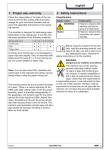
User manual
record system 20
Manufacturer
agtatec ag
Allmendstrasse 24
CH-8320 Fehraltorf
Service hotline
Distributor
Article no. 020.110.469A
Table of contents
Table of contents
1.
General remarks ...................................................................................................3
1.1.
1.2.
Target groups ................................................................................................................... 3
Door care.......................................................................................................................... 3
1.3.
Maintenance..................................................................................................................... 3
2.
Safety instructions ...............................................................................................4
2.1.
2.2.
Use for the intended purpose............................................................................................ 4
General safety and accident prevention regulations.......................................................... 4
2.3.
Control of safety devices .................................................................................................. 4
3.
Operating instructions .........................................................................................5
3.1.
3.2.
Selection of operating modes ........................................................................................... 5
Selection of special functions............................................................................................ 6
3.3.
3.4.
Locking the control unit over keyboard.............................................................................. 7
Locking the control unit with key a switch (option) ............................................................ 7
4.
Manual opening and closing in case of failure ..................................................8
4.1.
Manual opening (without manual unlocking device) .......................................................... 8
4.2.
Manual closing.................................................................................................................. 9
5.
Operating the door in emergency .....................................................................11
5.1.
5.2.
Emergency opening with current supply ......................................................................... 11
Emergency opening in case of power failure with auxiliary battery.................................. 11
5.3.
Emergency operating using bowden cable (option) ........................................................ 11
6.
Behaviour in event of faults ..............................................................................13
6.1.
6.2.
Display on the control unit............................................................................................... 13
Possible troubleshooting................................................................................................. 13
6.3.
Resetting the control module .......................................................................................... 13
6.4.
Control unit BDE-D does not react.................................................................................. 14
7.
Functions and safety check ..............................................................................15
7.1.
General remarks............................................................................................................. 15
7.2.
Technical data and operating conditions......................................................................... 15
7.3.
Monthly check-up list ...................................................................................................... 16
Page
2 / 16
General remarks
1.
General remarks
1.1.
Target groups
1
This user’s guide is meant for the following users:
•
•
Operators of the automatic sliding door record system 20:
the persons in charge of the technical maintenance of this door installation
End-users of the door installation:
the persons who use the door functions daily and have been appropriately trained
This manual explains how to operate the sliding door record system 20. It is the basis for optimal
functioning and gives instructions for troubleshooting. Excerpts of this document can also be given
to the persons responsible for the daily operating of the door.
The operator should read this user’s guide before commissioning the door and observe the safety
instructions!
Please keep this document in a safe, convenient place beside the sliding door.
1.2.
Door care
The entire door installation – including sensors and safety devices – can be cleaned with a damp
cloth and commercially available cleaning agents (do not use abrasive cleaning agents or any solvent). First test the product selected on a non-visible spot. The floor tracks should be kept free
from dirt.
NOTE
To perform this work it is recommended that the operating mode
(locked) or
(continuously open) be selected, in order to avoid possible injury due to uncontrolled
door movements.
1.3.
Maintenance
It is recommended that a technical safety test and a service be carried out by one of our record
service technicians or by an authorised partner, before first commissioning and as required – but
at least once a year.
A display on the BDE-D control unit will show when maintenance is due. These display messages
occur at various intervals which are defined by the number of opening cycles or after a certain operating time.
Regular testing and servicing by our fully trained staff – or by staff approved by record – offers the
best guarantee for durability and trouble-free, reliable operation.
We recommend that a service agreement be arranged with the record service centre in
charge of your region.
Seite
3 / 16
Safety instructions
2.
2
Safety instructions
The record system 20 sliding door has been developed with state of the art technology and recognised technical safety regulations.
2.1.
Use for the intended purpose
The record system 20 is designed exclusively for normal service in dry rooms.
The intended purpose includes observing the operating conditions as specified by the manufacturer, in addition to regular care, maintenance and repair.
Unauthorised modifications to the automatic door will release the manufacturer from all liability for
any resulting damage.
2.2.
General safety and accident prevention regulations
No safety devices (sensors, protective screens, etc.) may be dismantled or put out of service.
No objects may be present in the opening/closing area of the sliding door, in order to avoid
squashing and cutting!
NOTE
The installation is not intended to be disconnected from the mains at night!
2.3.
Control of safety devices
Beside the maintenance carried out at regular intervals by a record service technician or authorised person, it is recommended, for additional safety, that the operator regularly controls the essential elements of the door.
You will find a check-list of the functions to be tested monthly at the end of this document.
Seite
4 / 16
Operating instructions
3.
3
Operating instructions
The electronic control unit with display (BDE-D) has been designed to operate the automatic sliding door installation.
3.1.
Selection of operating modes
The electronic control unit BDE-D is a user-friendly input and output unit to control and customise
(optional) record door operation. The LCD display with backlight gives information about the door
status with symbols and clear text. Error messages are displayed as text.
Operating
mode
Key
Symbol
Function
•
Automatic
•
Continuously
open
One way
Locked
Reduced
opening width
Door opens unhindered from inside or
outside
Maximum opening width (summer opening)
•
Door remains open until another operating
mode is selected
•
Door opens only in one direction
(e.g. for shop closing time)
•
Door is closed and locked
(if locking system has been installed)
Door remains locked even in the case of
power failure
•
•
Door opens unhindered from inside or
outside
•
Reduced opening width (winter opening)
NOTE
Reduced opening width is also effective with the operating modes
tinuously open).
(one way) and
Seite
(con-
5 / 16
Operating instructions
3.2.
3
Selection of special functions
Key
Function
Manual mode
Manual mode
Single opening
Display
Description
• Press key twice running
• Door opens / stops on 2nd key stroke
• Door can be manoeuvred by hand
Back to operating mode
•
Activation of the selected key
(e.g. automatic)
•
Press key for 2 seconds
• Door can be manoeuvred by hand
Back to operating mode
•
Activation of the selected key
(e.g. automatic)
•
•
•
Door is closed and locked
1 keystroke unlocks the door
An opening/closing cycle is performed
•
Once closed, door locks again
Seite
6 / 16
Operating instructions
3.3.
3
Locking the control unit over keyboard
Key series
Display
Description
Locking the control unit
•
E
•
•
Undesired manipulation of the control unit is hindered
Panel is locked
Locked status of the BDE-D is displayed
Unlocking the control unit
E
•
Free selection of operating modes and special functions is ensured
NOTE
The installation remains in the mode of operation previously selected.
3.4.
Locking the control unit with key a switch (option)
The control unit BDE-D can be efficiently protected against unauthorised changes of operating
mode by an additional key switch. Such a key switch is usually placed near the BDE-D.
Seite
7 / 16
Manual opening and closing in case of failure
4.
Manual opening and closing in case of failure
4.1.
Manual opening (without manual unlocking device)
Initial situation:
4
Door is disconnected from the mains, blocked in closed position and locked.
•
Opening the operator casing
Note:
If you pull near the hinges, it will assist the opening of the
casing
•
Swivel out the red holding bar in order to keep the casing
in open position
•
The locking system is provided with an unlocking lever
•
Turn the lever clockwise
•
•
Door unlocks and can be pushed open by hand
Close the casing with a strong pressure on the area of the
hinges
Seite
8 / 16
Manual opening and closing in case of failure
4.2.
4
Manual closing
Initial situation:
Electric power is supplied. Door remains blocked in open position.
NOTE
According to the kind of failure, the procedure for a manual closing will be different. Please follow the steps described below.
4.2.1.
Manual closing – step 1
Key
Function
Display
Description
•
•
Press key twice running
Door can be opened or closed by hand
Manual mode
Temporary door operating
(e.g. in case of low outside temperatures)
Night locking
Locked
•
Press additionally the "locked" key
•
Slide the door by hand to the closed position
Door is closed – and locked (if applicable)
•
Inform record service point
(telephone number displayed on BDE-D)
NOTE
If the door still can not be moved by hand and locked, please follow the steps
described below.
Seite
9 / 16
Manual opening and closing in case of failure
4.2.2.
4
Manual closing – step 2
If the attempts to close and lock the door described under "step 1" have remained unsuccessful, it
indicates a severe failure. Please proceed as follows:
•
•
Set the door on "manual mode" with the control unit
(see § 4.2.1.)
Open the operator casing (swinging it out)
Note:
If you pull near the hinges, it will facilitate the opening of
the casing
•
Swivel out the red holding bar in order to keep the casing
in open position
•
•
Disconnect the installation from the power supply
The socket is located under the operator casing
Installations with in-built emergency battery:
•
•
Unscrew the battery fuse
The battery is located under the operator casing
•
Slide the door by hand to the closed position
•
Turn the unlocking lever clockwise and hold it in this position so that the door can close completely
Door will lock as soon as you release the unlocking lever
Manually check that the door is properly locked
Leaving the building is only possible through a second exit
Inform record service point
(telephone number displayed on BDE-D)
•
•
•
Seite
10 / 16
Operating the door in emergency
5.
5
Operating the door in emergency
In accordance with country-specific safety regulations (concept of emergency exit, etc.) the doors
are fitted with an emergency opening device.
5.1.
Emergency opening with current supply
By activating the emergency opening switch (optional), which must be placed beside the installation, the door will open as long as the operating mode "locked" has not been selected. In this operating mode the door will remain locked.
To re-start the installation again, the emergency opening switch must be reset by hand, either
through a rotation or a pulling (different procedures depending on the version of the switch).
5.2.
Emergency opening in case of power failure with auxiliary battery
•
•
•
•
5.3.
Emergency opening in case of power failure takes place via an auxiliary battery, which triggers a single opening of the door (except if function "locked" has been selected).
With a higher-performance battery, all functions of the automatic door are maintained over
several opening cycles. The number of openings depends essentially on the weight of the
door leaves and the state of the battery.
In case of low battery, the last movement is selectable – either opening or closing.
Unlocking the door is still possible with the key-operated contact/switch (optional).
Emergency operating using bowden cable (option)
This device, available in several versions, is mounted inside and/or outside and allows the unlocking of the door, according to the procedure below.
5.3.1.
Available versions
The available versions are illustrated below. They are basically identical in their functioning.
5.3.2.
Procedure for an emergency opening
Emergency opening
•
Open the unlocking flap
•
Pulling the unlocking flap downward unlocks the door
•
Display on the BDE-D:
à Error no. 31 / Emergency stop
Door can be slid open by hand
•
Seite
11 / 16
Operating the door in emergency
5.3.3.
5
Closing and locking the door
•
Operate the emergency opening
•
This causes the locking device to be "unlocked"
•
•
Slide the door by hand to the closed position
Keep the door leaves in the closed position
•
•
Close the unlocking flap
The door is now locked
•
Check by hand that the door really is locked
NOTE
Same procedure for the other actuators.
Seite
12 / 16
Behaviour in event of faults
6.
6
Behaviour in event of faults
In case the installation fails, a message is displayed on the control unit BDE-D.
6.1.
6.2.
Display on the control unit
•
Status messages are displayed with status number and text.
•
•
The display changes alternately from white to black.
After 10 seconds, the telephone number of the relevant service centre is alternately displayed.
Possible troubleshooting
•
•
•
•
Based on the status display some errors can sometimes be eliminated.
If you are not sure, please contact the relevant service centre.
Before you call, write down the data displayed on the BDE-D. This information provides the
technician with important indicators for troubleshooting.
If several status messages are active at the same time, they are numbered: e.g. error 1/2
Procedure
Information
6.3.
Status text and number
•
Is automatically displayed on
the BDE-D
Software versions
•
Press the following BDE-D
key for 2 seconds
E
Display examples
Resetting the control module
In certain cases, failures can be repaired by resetting the control (STM). Proceed as follows:
•
Make sure that the operator casing is closed, and that nobody is obstructing the door or is approaching it, thereby triggering an opening.
E
Press record key > 5 seconds
No
C
E
Yes
•
The door is reset.
•
•
After a reset takes place, the first door movement occurs at reduced speed.
If an error is still displayed on the BDE-D after a reset of the control module, please contact
our service centre, stating the error message.
Seite
13 / 16
Behaviour in event of faults
6.4.
6
Control unit BDE-D does not react
If the control unit BDE-D does not react when the keys are pressed or if no message appears on
the display, a reset of the control unit can eliminate the problem.
Proceed as follows:
RESET HARDWARE BDE-D
E
Press record key > 12 seconds
Display without any message
Connection to control…
Connection has been established (example)
•
•
After resetting, the control unit is again operational.
If this is not the case, please inform our service centre.
Seite
14 / 16
Functions and safety check
7.
Functions and safety check
7.1.
General remarks
7
According to the legal provision in force, the operating entity of the automatic door is responsible
for its maintenance and for the users’ safety, as soon as the installation has been handed over.
The monthly inspection of single elements by the operator requires little time investment and reinforces the prevention of accidents caused by an inappropriate use of the door.
7.2.
Technical data and operating conditions
7.2.1.
Power supply data
Mains voltage (230V):
100-240 VAC, 50 / 60 Hz
Rated power:
140 VA
Ambient conditions
Temperature range:
-15° to +50° C
Humidity range:
up to 85% relative humidity, non-thawing
7.2.2.
Seite
15 / 16
Functions and safety check
7.3.
7
Monthly check-up list
Test / control
Motion detector
Door leaf / side screen
Door leaf guides
Procedure
•
•
•
•
Verify the state of the glazing •
•
Verify the state of the seals
and profiles
•
•
Door leaf must slide smoothly
•
These could be damaged by •
impacts (e.g. from trolleys)
•
Door leaf guides can show
exceptional signs of wear
and tear due to intensive use
as well as dirt
Set the door on manual
mode (see chapter 3.2.)
No glass damage
•
Control the door leaf guides
•
The sensor must cover the
whole width of passage
The door opens in time and at
an appropriate speed to allow
unhampered passage
through the doorway
No seals torn off (preventing
energy loss)
The door is the “visiting card“
for your company. Take care
it is maintained in a perfect
condition
•
•
Full width floor track
(instead of single door leaf guides)
Walk at normal speed towards the door (from inside
or outside)
Result expected
Bottom or vertical profiles
show no scratch marks
Door leaf guides must not
produce any unusual noise
during the opening/closing
phase
•
Door leaf must slide smoothly
•
The movement of the door
must not be hindered by dirt
•
Clear the track of dirt, cigarette butts, etc.
Operator casing
•
Check the attachment of the
operator casing
•
It must be completely closed
and must correctly engage in
the hinges
Protective screen
(optional – country-specific)
•
Check the mechanical state •
of the protective screen
Particularly check the closing
mechanism
A protective screen reduces
risk of squashing and cutting
•
Seite
16 / 16