1
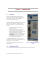
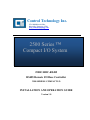
Control Technology Inc. 5734 Middlebrook Pike Knoxville, Tennessee 37921 www.controltechnology.com Toll Free: 800-537-8398 2500 Series ™ Compact I/O System 2500C-RBC-RS485 RS485 Remote I/O Base Controller 2500 SERIES® COMPACT I/O INSTALLATION AND OPERATION GUIDE Version 1.0 Copyright © 2014 Control Technology Inc. All rights reserved. This manual is published by Control Technology Inc., 5734 Middlebrook Pike, Knoxville, TN 37921. This manual contains references to brand and product names which are trade names, trademarks, and/or registered trademarks of Control Technology Inc. Siemens® and SIMATIC® are registered trademarks of Siemens AG. Other references to brand and product names are trade names, trademarks, and/or registered trademarks of their respective holders. DOCUMENT DISCLAIMER STATEMENT Every effort has been made to ensure the accuracy of this document; however, errors do occasionally occur. CTI provides this document on an “as is” basis and assumes no responsibility for direct or consequential damages resulting from the use of this document. This document is provided without express or implied warranty of any kind, including but not limited to the warranties of merchantability or fitness for a particular purpose. This document and the products it references are subject to change without notice. If you have a comment or discover an error, please call us toll-free at 1-800-537-8398 or email us at [email protected]. REVISION HISTORY V1.0 05/28/14 Original Issue CTI 2500C-RBC-RS485 Installation and Operation Guide V1.0 PREFACE This Installation and Operation Guide provides reference information for the CTI 2500C-RBCRS485 RS485 Remote Base Controller. The information in this manual is directed to individuals who will be installing the module and configuring it for use with a CTI 2500 Series® or Simatic® 505 Processor. We assume you are familiar with the installation and operation of: 2500 Series® programmable controllers IO Netwroking PLC Programming Software CTI 2500C-RBC-RS485 Installation and Operation Guide V1.0 USAGE CONVENTIONS NOTE: Notes alert the user to special features or procedures. CAUTION: Cautions alert the user to procedures that could damage equipment. WARNING: Warnings alert the user to procedures that could damage equipment and endanger the user. CTI 2500C-RBC-RS485 Installation and Operation Guide V1.0 TABLE OF CONTENTS CHAPTER 1. DESCRIPTION ..................................................................................5 1.1 1.2 Introduction .....................................................................................................5 Communication Ports .....................................................................................5 1.2.1 1.2.2 Serial Port I/O Port 6 6 CHAPTER 2. INSTALLATION ................................................................................7 2.1 Installation Planning .......................................................................................7 2.1.1 2.1.2 2.1.3 2.1.4 2.2 2.3 2.4 2.5 Choosing Remote I/O Media Selecting a Remote Base Address Setting Module Hardware Options Connecting to Remote I/O Cable 7 7 7 7 Unpacking the Module ...................................................................................7 2500-RBC-RS485 Module Board Layout ......................................................8 2500C-RBC-RS485 Front Panel Layout .......................................................9 Configuring the Module ............................................................................... 10 2.5.1 2.5.2 2.5.3 Setting the RS232 Port Baud Rate Setting the Output State on Communication Loss Setting the Remote Controller Base Station Address 10 11 12 2.6 Physical Installation ..................................................................................... 12 2.7 Connecting to the RS232 Port .................................................................... 13 2.8 Connecting the Remote I/O Cable ............................................................. 13 2.9 Operation of LED Display ........................................................................... 14 2.10 System Status Words ................................................................................. 15 Appendix A. REMOTE I/O INSTALLATION GUIDELINES ................................................. 16 A. 1. Cable Layout Planning ................................................................................ 16 A. 2. Cable Selection ........................................................................................... 16 A. 3. Cable Lengths ............................................................................................. 17 A. 4. Bus termination ........................................................................................... 19 A. 5. Cable Routing and Layout Guidelines ........................................................ 20 A. 6. Laying Cables Outside of Control Cabinets ............................................... 20 Appendix B. I/O “SAFE STATE” OPERATION .................................................................... 21 Appendix C. SPECIFICATIONS ........................................................................................... 22 General 22 Ports 22 Environmental ........................................................................................................... 22 Appendix D. LIMITED PRODUCT WARRANTY .................................................................. 23 CTI 2500C-RBC-RS485 Installation and Operation Guide V1.0 3 TABLE OF FIGURES Figure 1. 2500C-RBC-RS485 Front Panel .............................................................................5 Figure 2. 2500C-RBC-RS485 2500C-RBC-RS485 Module Board Layout .............................8 Figure 3. 2500C-RBC-RS485 Front Panel .............................................................................9 Figure 4. 2500C-RBC-RS485 Front Panel ...........................................................................10 Figure 5. 2500C-RBC-RS485 Freeze Jumper Selection Jumper .........................................11 Figure 6. 2500C-RBC-RS485 Serial Port Pin outs ...............................................................13 Figure 7. 2500C-RBC-RS485 Serial Port Pin outs ...............................................................13 Figure 8. Remote I/O Installation .........................................................................................16 Figure 9. Trunk Length Measurement..................................................................................19 Figure 10. T-Connection Trunk Length ................................................................................19 4 CTI 2500C-RBC-RS485 Installation and Operation Guide V1.0 Chapter 1. DESCRIPTION 1.1 Introduction The CTI 2500C-RBC-RS485 RS485 Remote Base Controller is a member of Control Technology's family of I/O modules compatible with programmable controllers from Siemens® and CTI. The 2500C-RBC-RS485 RS485 Remote Base Controller (RBC) allows a 2500 Series® Compact I/O base to function as a remote base. It provides the following functions: Compatible with CTI 2500 Series® and Simatic® 505® CPUs. Can be used in currently-available CTI 2500 Series® Compact 4, 8, and 16-slot bases Supports communication speeds 1Mbits/sec and maximum cable distance of 1000 meters LED display which shows error and status codes Front panel thumbwheel switch for setting the station address On-board RS232 port which can be used for PLC programming and configuration. The 2500C-RBC-RS485 resides in 2500 Series® Compact base. It installs in the second slot from the left, adjacent to the power supply module. Do not install this module into a normal I/O slot, as damage can occur. 1.2 Figure 1. 2500C-RBC-RS485 Front Panel Communication Ports The 2500C-RBC-RS485 RS485 RBC has two communication ports on the front panel. CTI 2500C-RBC-RS485 Installation and Operation Guide V1.0 5 1.2.1 Serial Port The RS232 port is provided to interface to PLC programming and configuration tools such as TISOFTTM. A standard 9-pin PC-compatible RS232 serial cable is used to connect to the programming device or modem. The port pinout is provided in Section 2.6 of this manual. 1.2.2 I/O Port The I/O Port connects the 2500C-RBC-RS485 to a SIMATIC® 505 compatible RS485 Remote I/O channel. This enables the remote CPU to control the I/O modules in the base where the RBC is located. The Remote I/O Port interface is a 9-pin D-Shell connector as detailed in Section 2.7 of this manual. Recommended guidelines for planning, selection, and installation of Remote I/O system is included in Appendix A. 6 CTI 2500C-RBC-RS485 Installation and Operation Guide V1.0 Chapter 2. INSTALLATION The installation of the Model 2500C-RBC-RS485 RS485 Remote Base Controller consists of the following steps: 1) Planning the installation 2) Verifying power requirements 3) Unpacking and configuring the module 4) Physical installation 5) Connecting cables 6) Checking the module operation 2.1 Installation Planning 2.1.1 Choosing Remote I/O Media The 2500C-RBC-RS485 attaches directly to the RS485 Remote I/O cable using a DB9 connector. We recommend using cable designed specifically for RS485 systems, such as Belden 3105A. See Appendix A for information related to cable specifications, layout, and installation. 2.1.2 Selecting a Remote Base Address Before proceeding, you must determine what address you will assign to the RBC. Remote Base addresses range from 1 to 15. In CTI 2500 Series® and Simatic® 505® systems, address 0 is reserved for the local base where the CPU is installed. Note that each Remote Base on the Remote I/O channel must have a unique address 2.1.3 Setting Module Hardware Options The RBC includes a hardware setting for selecting the state of the base discrete outputs in the event of a loss of communication with the CPU. The module can be configured to set all outputs off, or to leave outputs at their last states. 2.1.4 Connecting to Remote I/O Cable The Remote I/O connector should be wired as shown in Section 2.7. 2.2 Unpacking the Module Open the shipping carton and remove the special anti-static bag that contains the module. After discharging any static build-up, remove the module from the static bag. Do not discard the static bag. Always use this bag for protection against static damage when the module is not inserted into the I/O base. CAUTION: The components on the 2500C-RBC-RS485 module printed circuit card can be damaged by static electricity discharge. To prevent this damage, the module is shipped in a special anti-static bag. Static control precautions should be followed when removing the module from the bag and when handling the printed circuit card during configuration. CTI 2500C-RBC-RS485 Installation and Operation Guide V1.0 7 2.3 2500-RBC-RS485 Module Board Layout Freeze Jumper JP4 Module Front Panel Backplane Connector Serial Port Baud Rate Selection Switches Figure 2. 2500C-RBC-RS485 2500C-RBC-RS485 Module Board Layout 8 CTI 2500C-RBC-RS485 Installation and Operation Guide V1.0 2.4 2500C-RBC-RS485 Front Panel Layout Status Indicator RBC Address Selection Thumbwheel Switch Serial RS-232 9pin Port Remote RS-485 9pin Port Figure 3. 2500C-RBC-RS485 Front Panel CTI 2500C-RBC-RS485 Installation and Operation Guide V1.0 9 2.5 Configuring the Module There are three steps to configuring the module and making it fully operational: 1. Setting the RS232 Port baud rate 2. Setting the Remote Base Controller address 3. Setting the output state on communication loss (Freeze Jumper) Figure 2. 2500C-RBC-RS485 2500C-RBC-RS485 Module Board Layout indicates the location of the RS232 port baud rate selection switches, the RBC station address thumbwheel, and Freeze Jumper. The remainder of this section describes the function of the individual settings. 2.5.1 Setting the RS232 Port Baud Rate Switches SW1-SW4 are used for setting the baud rate of the RS-232 serial port. The supported baud rates are shown in the following table. All other switch combinations are invalid. Serial Port Selection Switches Note: The picture shows the Baud Rate set at 9600. Figure 4. 2500C-RBC-RS485 Front Panel 10 Baud Rate SW1 SW2 SW3 SW4 19200 1 1 0 1 9600 1 1 1 1 2400 0 1 1 1 1200 1 0 1 1 300 0 0 1 1 CTI 2500C-RBC-RS485 Installation and Operation Guide V1.0 2.5.2 Setting the Output State on Communication Loss When I/O channel communication to a remote base is lost, the state of the discrete outputs is determined by the selection made on the 2500C-RBC-RS485 jumper JP4 (Off/Freeze). Figure 5. 2500C-RBCRS485 Freeze Jumper Selection Jumper shows the location of the jumper on the 2500C-RBC-RS485. NOTE: The 2500C-RBC-RS485 ships with the FREEZE jumper in the OFF setting. If the jumper JP4 is missing from the board, the 2500C-RBC-RS485 defaults to the OFF setting. For discrete output modules, the state of the outputs is determined solely by the position of the Off/Freeze jumper JP4 on the 2500C-RBC-RS485. For analog/word output modules, the state of the outputs is influenced not only by the position of the Off/Freeze jumper but by the output module’s (Zero/Hold Last Value) selection, if the module has that option. See the table below. RBC Off/Freeze Analog/Word Module Analog/Word Output State Selection Zero/Hold Selection Off Zero Zero* Off Hold Last Value Last Value Off No selection Last Value Freeze Zero Last Value Freeze Hold Last Value Last Value Freeze No selection Last Value *see the user manual of your analog/word output module for details Notice that the FREEZE option on the RBC overrides the Zero selection on the analog/word output module; likewise, when Hold Last Value is selected on the analog/word output module, that selection overrides the OFF option on the RBC jumper. WARNING: If the RBC fails or loses power during system operation, all outputs will turn OFF(0) regardless of the Freeze Jumper setting. This could result in damage to equipment and/or serious injury to personnel. JP4 Freeze Jumper Shipped in the OFF position on PINS 1 & 2 (Note Shown in the ON Position) This diagram shows other jumpers in place. When shipped these jumpers are not usually populated. Figure 5. 2500C-RBC-RS485 Freeze Jumper Selection Jumper CTI 2500C-RBC-RS485 Installation and Operation Guide V1.0 11 2.5.3 Setting the Remote Controller Base Station Address A thumbwheel switch is provided to set the base address to the 2500C-RBC-RS485 for Remote I/O station identification. A maximum of 15 remote bases can be connected to the CTI 2500 Series® CPU or Siemens® 545/555/575 CPU. NOTE: When connecting the 2500C-RBC-RS485 to a CTI 2500 Series® CPU or Siemens® 545/555/575 CPU, only addresses between 1 and 15 are valid. Each installed 2500C-RBCRS485 must have a unique station number. Care should be taken to prevent circumstances which cause the CPU to lose communication with the 2500C-RBC-RS485 while the system is operating. Loss of communication between the CPU and RBC will cause the base to be logged off from the CPU. This can cause intermittent process operation. WARNING: The following events will cause loss of communication with the 2500C-RBC-RS485 and result in the base being logged off from the CPU. 1) Duplication of the station address between RBC’s attached to the same CPU. 2) Changing the thumbwheel switch station address while the system is operating. These events could cause unpredictable process operation and result in damage to equipment and/or serious injury to personnel. When a base if logged off, the CPU zeroes all image register input points associated with the base and all outputs go to the value determined by the installed output module. Discrete outputs turn OFF (0) and Analog/Word outputs are set according to the Zero/Hold Last Value settings in each particular module. Your program can monitor the CPU Status Words to detect this condition and control the outputs from other remote bases as appropriate for the application. Details on the Status Words and programming examples can be found in the SIMATIC® 545/555/575 Programming Reference User Manual . 2.6 Physical Installation To insert the module into the I/O base, hold the top and bottom of the bezel and slide the module carefully into the slot, pushing it all the way into the base. If you have inserted the module correctly, you will feel a slight increase in resistance as the module mates with the base backplane connector. Once the module is fully seated in the slot, tighten the captive screws at the top and bottom to hold the module in place. To remove the module from the I/O base, loosen the captive screws, and then pull the module from the base. Take care not to damage the connector at the back of the module when inserting or removing the module. 12 CTI 2500C-RBC-RS485 Installation and Operation Guide V1.0 2.7 Connecting to the RS232 Port The RS232 port is provided to interface to PLC programming and configuration tools such as TISOFTTM. The use of this port is optional. A standard 9-pin PC RS232 serial cable can be used to connect to the programming device or modem. The port details are shown in Figure 3. 9-Pin D-Shell Male Connector Compatible with standard PC Serial Port 1 DSR (6) 6 DCD (1) RxD (2) TxD (3) RTS (7) CTS (8) DTR (4) SGND (5) 9 5 Figure 6. 2500C-RBC-RS485 Serial Port Pin outs 2.8 Connecting the Remote I/O Cable The I/O Port connects the 2500C-RBC-RS485 to a SIMATIC® 505 compatible RS485 Remote I/O channel. This enables the remote CTI 2500 Series® or Simatic® 505® CPU to control the I/O modules in the base where the RBC is located. The Remote I/O Port interface is a 9-pin D-Shell connector with pinout as shown in Figure 3. Recommending wiring for the Remote I/O cabling is detailed in Siemens® 545/555/575 System Manual. Figure 4 shows the pinout for the I/O Port. 9-Pin D-Shell Female Connector 5 9 GND (5) TX/RX- (8) TX/RX+ (3) 6 1 Figure 7. 2500C-RBC-RS485 Serial Port Pin outs CTI 2500C-RBC-RS485 Installation and Operation Guide V1.0 13 2.9 Operation of LED Display The LED Display is used to indicate the status of the 2500C-RBC-RS485 Remote Base Controller as shown in the following table: Display Definition Communications to RBC Comment / Action 0 Module Ready OK Fully Operational and online with CPU. 1 Diagnostics Failure None Serious malfunction. Place system in safe state and contact CTI Technical Support. 2 Module Mismatch OK I/O modules installed do not match the expected configuration in the CPU. 3 I/O Communications timeout Failed There is no communication with the CPU. Place the system in a safe state. Check power, cabling, and connection to the CPU. 4 Ram Parity Error Failed Serious malfunction. Place system in safe state and contact CTI Technical Support. 5 Standby, No Configuration None Not used. 6 Address Mismatch OK Not used. 7 Communications OK, No Configuration OK 2500C-RBC-RS485 is not configured. Configure RBC in CPU. 8 Watchdog timeout Failed Serious malfunction. Place system in safe state and contact CTI Technical Support. *blank* No Code Displayed None Serious condition. 2500C-RBC-RS485 is not operational. If power to base is OK, contact CTI Technical Support. C A,B,E 14 Not Used Internal Failure Not Used. Failed Hardware failure detected during power on initialization tests. CTI 2500C-RBC-RS485 Installation and Operation Guide V1.0 2.10 System Status Words There are a number of system status words which are important in observing remote I/O system operation and isolating problems. If you are experiencing remote I/O problems, you should pay careful attention to the following status words. STW2 STW11-26 STW145 STW146 STW168 STW184 STW210 STW455-461 STW471-485 STW487-501 Base controller status I/O module status Remote I/O receive errors Remote I/O timeout errors Dual RBC Status(not Used.Future) I/O module mismatch Remote I/O base poll enable flags Remote base receive errors Remote base abnormal logoff counts Remote base timeout counts More complete information and a list of the 2500 Series® Processor System Status Words can be found in the 2500 Series® Processor Installation and Operation Guide: http://www.controltechnology.com/Files/Products/2500-(Classic)/2500-Cxxx/manuals/CTI2500-IOG-(62-370) CTI 2500C-RBC-RS485 Installation and Operation Guide V1.0 15 Appendix A. REMOTE I/O INSTALLATION GUIDELINES These Remote I/O Installation Guidelines are based on standard RS485 wiring practices. The Remote I/O cable system consists of a main trunk line and drop lines which connect the CPU/Local Base and Remote Base(s) to the trunk line by means of terminal blocks as shown in Figure 8. Remote I/O Installation. Local Base T = Terminal Block Drop Line T T T Trunk Lines Drop Lines Remote Base Remote Base Figure 8. Remote I/O Installation A. 1. Cable Layout Planning Use the following guidelines for planning the Remote I/O cable routing and locations: The ideal cable installation is a single, unbranched trunk line with short drop lines and termination resistor at each end Maximum length of a drop line should not exceed 33 feet (10 m) Drop lines less than 3.3 feet (1 m) do not count toward cable length calculations The total length of all drop lines should be much less than the length of the trunk line When multiple bases must be located in close proximity, connect all bases in a “daisychain” arrangement with a single drop line. A. 2. Cable Selection Data transfer in the Remote I/O systems is based on a symmetrical RS485 bus system using shielded twisted pair cable. The cable shield is used to improve the immunity to electromagnetic interference. The ideal cable provides low signal attenuation for long trunk lines and flexibility for ease of installation. The recommended cable should include the characteristics as shown in the following table. 16 CTI 2500C-RBC-RS485 Installation and Operation Guide V1.0 CTI recommends Belden 3105A cable for wiring remote I/O. The following table contains the general recommended cable specs for RS485 remote I/O wiring and the preferred Beldon cable type specifications. Cable Characteristic Conductors Recommended 18AWG to 22AWG uniform twisted-pair 100% shield coverage Shielding 100 Ω to 150 Ω Characteristic Impedance Capacitance DC Resistance Attenuation Velocity of Propagation Operating Temperature Belden® 3105A 2-conductors,22AWG,.030 in (7.5mm), 7x30 stranded 100% coverage with 90% copper braid plus drain wire 120 Ω < 50 pF/m Resistance of installed length < characteristic impedance < 1.0 dB/100 ft (1.0 dB/ 30 m) > 65% 11 pF/ft (36 pF/m) 14.7 Ω/1000 ft (48.2 Ω/km) 0 to +60 ºC -20 to +60 ºC 0.5 dB/100 ft (0.5 db/30 m) @ 1MHz 78% Alternatively, Beldon 9860, 9271, and 9182 cable can be used to wire your remote I/O. The table below gives the cable specifications for these models. Alternative Cable Specs Belden Cable Type 9182 9271 9860 Outside Diameter 0.35 in. 8.9 mm 0.24 in 6.1 mm 0.44 in. 11.2.mm Impedance 150 ohm Capacitance 28.9 pf/m Velocity 0.78c 124 ohms 40 pf/m 0.66c 124 ohms 35.8 pf/m 0.78c Center Conductor 22 AWG 19x34 46 ohm/km 25 AWG 7x33 104.3 ohm/km 16 AWG Solid 13.8.ohm/km A. 3. Cable Lengths Maximum permissible cable length is dependent on cable characteristics and number of terminal blocks used in the installation. Terminal blocks are used to connect drop lines and/or extend Remote I/O cable trunk line. The following table contains the maximum recommended cable length (Trunk Length + Drop Lines) for Belden® 3105A cable. It is possible to have longer cable runs if larger diameter wire is used. CTI 2500C-RBC-RS485 Installation and Operation Guide V1.0 17 Number of Installed Drop Lines Maximum Cable Length in Feet (Meters) 2-5 6 7 8 9 10 11 12 13 14 15 16 17 Number of Drop Lines 2-5 6 7 8 9 10 11 12 13 14 15 16 18 Belden 3105A 2200 (670) 2133 (650) 2067 (630) 2000 (610) 1933 (589) 1867 (569) 1800 (548) 1733 (528) 1667 (508) 1600 (488) 1533 (467) 1467 (447) 1400 (427) Belden 9182 2200 ft (670 m) 2133 ft (650 m) 2067 ft (630 m) 2000 ft (610 m) 1933 ft (589 m) 1827 ft (569 m) 1800 ft (548 m) 1733 ft (528 m) 1677 ft (508 m) 1600 ft (488 m) 1533 ft (476 m) 1400 ft (427 m) Maximum Distance Belden 9271 Belden 9860 1100 ft (335 m) 1067 ft (325 m) 1033 ft (315 m) 1000 ft (305 m) 967 ft (295 m) 933 ft (284 m) 900 ft (274 m) 867 ft (264 m) 833 ft (254 m) 800 ft (244 m) 767 ft (234 m) 733 ft (223 m) 3300 ft (1006 m) 3200 ft (975 m) 3100 ft (945 m) 3000 ft (914 m) 2900 ft (884 m) 2800 ft (853 m) 2700 ft (823 m) 2600 ft (792 m) 2500 ft (762 m) 2400 ft (732 m) 2300 ft (701 m) 2200 ft (671 m) CTI 2500C-RBC-RS485 Installation and Operation Guide V1.0 Cable trunk length is measured from the CPU to the most distant base. CPU Terminating Resistor Terminating Resistor Max Trunk Length T T T T T = Terminal Block Figure 9. Trunk Length Measurement By using a T-configuration as shown in Figure 10. T-Connection Trunk Length, the maximum trunk length can be extended to twice the length shown in the table on the previous page. CPU Terminating Resistor Terminating Resistor Max Trunk Length T T T Max Trunk Length T T T T Total Trunk Line Length T = Terminal Block Figure 10. T-Connection Trunk Length A. 4. Bus termination In order to minimize cable reflections and ensure a defined noise level on the data lines, the data transfer cable MUST be terminated at both ends with a terminating resistor approximating the characteristic impedance of the cable. For Belden® 3105A cable, a termination resistor value of 120 ohms should be connected across the TX/RX+ and TX/RX- signal lines. CTI 2500C-RBC-RS485 Installation and Operation Guide V1.0 19 A. 5. Cable Routing and Layout Guidelines Cables containing the following should be routed Bus signals, e.g. Remote I/O Data signals for PCs, programming devices, printers etc. Screened analog inputs Unscreened DC voltages (<= 60V) in the same cable loom or cable duct Screened process signals (<= 25 V) Unscreened AC voltages (<= 25V) Coaxial cables for monitors DC voltages from 60 V to 400 V (unscreened) AC voltages from 25V to 400 V (unscreened) in separate cable looms or cable ducts without minimum spacing requirements DC and AC voltages > 400 V (unscreened) Telephone cables For areas with explosion hazard in separate cable looms or cable ducts without minimum spacing requirements A. 6. Laying Cables Outside of Control Cabinets All cable ducts should be constructed of electrically conducting material and connected to functional ground at regular intervals. Cables should not be subject to mechanical loads which exceed the manufacturer’s specifications. If this cannot be avoided, additional protective measures should be taken, such as laying the cables in a steel pipe or rugged metal duct. The pipe or duct should then be grounded at regular intervals and protected against corrosion. 20 CTI 2500C-RBC-RS485 Installation and Operation Guide V1.0 Appendix B. I/O “SAFE STATE” OPERATION The 2500C-RBC-RS485 Remote Base Controller is designed to place the I/O on its base into a “safe state” on the occurrence of various kinds of system failures involving the PLC processor and communications cabling. The safe state for the I/O depends on the setting of the FREEZE jumper (seeSetting the Output State on Communication Loss). The following situations will cause the outputs go to the safe state: 1. When the PLC goes to fatal error, all remote bases go to the safe state. 2. When you pull a cable at the RIO-A, single base 3. When you send any of the three software restart commands (partial restart, complete restart, power up restart). All remote bases go to the safe state. 4. When you trigger RIO-A diagnostics to a system that is not a dual RIO-A configuration. 5. When you have an enabled and configured base and then you disable it. 6. When you have an enabled and configured base that is not a dual RIO-A configuration and then “clear base” 7. When you extract the active RIO-A from a dual rack configuration. CTI 2500C-RBC-RS485 Installation and Operation Guide V1.0 21 Appendix C. SPECIFICATIONS General Module Size: Double-Wide Backplane Power Consumption: 2.5 watts Compatibility: CTI 2500 Series® and Simatic® 505® CPU’s All currently-available CTI and Siemens® 505 4-, 8-, 11-, and 16-slot bases Single and Dual-Media configurations Display: Shows RBC status and error codes Output State Selection: Determines state of outputs when I/O channel communication is lost: OFF All outputs are turned off FREEZE All outputs hold their last value Hardware User Configuration Options: RS232 Serial Port baud rate (dipswitch) RBC Station Address (thumbwheel) Diagnostic Data: RBC Status Indication in CPU Status Word and Front Panel LED Display Ports Remote I/O: 9-Pin D-Shell Female Connecter RS232 Serial: 9-Pin D-Shell Male Connecter, PC compatible pinout Environmental Operating Temperature: 0º to 60º C (32º to 185º F) Storage Temperature: -40º to 85º C (-40º to 185º F) Humidity: 5% to 95%, non-condensing Agency Approvals Pending: UL, ULC, CE, Class I Division 2 Hazardous Location Shipping Weight: 1.5 lb. (0.68 Kg) 22 CTI 2500C-RBC-RS485 Installation and Operation Guide V1.0 Appendix D. LIMITED PRODUCT WARRANTY For product Warranty information, please see our standard product warranty at http://www.controltechnology.com/support/warranty/ In the event that the Product should fail during or after the warranty period, a Return Material Authorization (RMA) number can be requested orally or in writing from CTI main offices. Whether this equipment is in or out of warranty, a Purchase Order number provided to CTI when requesting the RMA number will aid in expediting the repair process. The RMA number that is issued and your Purchase Order number should be referenced on the returning equipment's shipping documentation. Additionally, if the product is under warranty, proof of purchase date and serial number must accompany the returned equipment. The current repair and/or exchange rates can be obtained by contacting CTI's main office at 1-800-537-8398. When returning any module to CTI, follow proper static control precautions. Keep the module away from polyethylene products, polystyrene products and all other static producing materials. Packing the module in its original conductive bag is the preferred way to control static problems during shipment. Failure to observe static control precautions may void the warranty. For additional information on static control precautions, contact CTI at 1-800-537-8398. CTI 2500C-RBC-RS485 Installation and Operation Guide V1.0 23