1
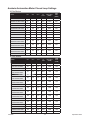
Dip Switch Settings (cont.)
Function
SW1
SW2
SW3
SW4
SW5
Constant Speed Mode (Closed Loop)
Off
---
---
---
---
Voltage Controlled Speed Mode (Open Loop)
On
---
---
---
---
Closed Loop Compensation 1
---
---
---
---
---
Closed Loop Compensation 2
---
---
---
---
---
Closed Loop Compensation 3
---
---
---
---
---
Standard Product (Ready to Ship)
On
Off
Off
Off
Off
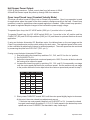
SW2: Open Loop and Closed Loop. If Closed Loop selected, Closed Loop
compensation switches must be set according to motor speed desired.
Motor Freewheel
The motor freewheel feature allows the de-energizing of the motor phases. A high (open) input at
this input causes the motor to run at the given speed, while a low at this input causes the motor to
coast to a stop.
Motor Run/Stop
The motor run/stop feature allows the stopping of a motor by shorting out the bottom drives of the
three phases. A low at this input allows the motor to run, while a high (open) input does not allow
motor operation and if operating causes rapid deceleration.
Motor Direction
The motor direction feature allows the changing of the rotation of the motor. This input should not be
changed while motion is in progress. A high (open) input causes the motor to turn in the CW direction, while a low at this input causes the motor to turn in the CCW direction.
Speed Adjust Setting
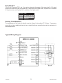
There are three ways to set the speed on this drive. One is to use the on-board or external potentiometer. To others is to use an external voltage. To use the on-board potentiometer, set INT/EXT
SPD switch to the off position (default). To use the external 10K potentiometer or external 0V to 5V
voltage speed setting, set INT/EXT SPD switch to the on position. If a voltage is used to control the
speed of the motor, the 0V to 5V voltage can be tied on Vcontrol (TB3 - pin 6) with respect to GND
(TB3 - pin 7). If an external potentiometer is used to control the speed of the motor, connect the pot
wiper to Vcontrol (TB3 - pin 6), the positive end of the potentiometer to Hall Power (TB1 - pin 1) and
the negative end to GND (TB3 - pin 7).
The maximum voltage that can be placed on Vcontrol is 15V. A voltage exceeding 15V may cause
damage to the driver. If a voltage other than 0V to 5V is needed to control the speed of the motor,
contact Anaheim Automation for custom tuning of the Vcontrol input.
L010403
8
September 2012