1
UM0851
User manual
Linux support package (LSP) v2.3 for SPEAr
Introduction
SPEAr is a family of highly customizable ARM-based embedded MPUs suitable for use in
many different kinds of application.
SPEAr Linux Support Package consists of a collection of all the Linux drivers that control the
specific hardware controllers embedded in SPEAr as well as the set of bootloaders for
performing the low level hardware configuration and loading of the Linux OS.
LSPv2.3 handles, in a single source tree, the following SPEAr devices: SPEAr600,
SPEAr300, SPEAr310 and SPEAr320.
LSPv2.3 is integrated into the STLinux 2.3 distribution, which is a full featured distro
consisting of more than 500 RPM packages.
Please refer to http://www.stlinux.com for more details.
May 2010
Doc ID 16604 Rev 2
1/245
www.st.com
www.BDTIC.com/ST
Contents
UM0851
Contents
1
Boot loader overview . . . . . . . . . . . . . . . . . . . . . . . . . . . . . . . . . . . . . . . 13
1.1
XLoader . . . . . . . . . . . . . . . . . . . . . . . . . . . . . . . . . . . . . . . . . . . . . . . . . . 13
1.1.1
1.2
Building XLoader . . . . . . . . . . . . . . . . . . . . . . . . . . . . . . . . . . . . . . . . . . 14
U-Boot . . . . . . . . . . . . . . . . . . . . . . . . . . . . . . . . . . . . . . . . . . . . . . . . . . . 14
1.2.1
U-Boot overview . . . . . . . . . . . . . . . . . . . . . . . . . . . . . . . . . . . . . . . . . . . 15
1.2.2
Features . . . . . . . . . . . . . . . . . . . . . . . . . . . . . . . . . . . . . . . . . . . . . . . . . 15
1.2.3
Building U-Boot . . . . . . . . . . . . . . . . . . . . . . . . . . . . . . . . . . . . . . . . . . . 15
1.2.4
U-Boot commands . . . . . . . . . . . . . . . . . . . . . . . . . . . . . . . . . . . . . . . . . 16
1.2.5
Booting Linux with U-Boot . . . . . . . . . . . . . . . . . . . . . . . . . . . . . . . . . . . 21
2
Linux OS and device driver general information . . . . . . . . . . . . . . . . . 23
3
Platform section . . . . . . . . . . . . . . . . . . . . . . . . . . . . . . . . . . . . . . . . . . . 25
3.1
3.2
3.3
4
3.1.1
Hardware overview . . . . . . . . . . . . . . . . . . . . . . . . . . . . . . . . . . . . . . . . 26
3.1.2
Software overview . . . . . . . . . . . . . . . . . . . . . . . . . . . . . . . . . . . . . . . . . 26
3.1.3
GPT driver usage . . . . . . . . . . . . . . . . . . . . . . . . . . . . . . . . . . . . . . . . . . 29
Vector interrupt controller (VIC) driver . . . . . . . . . . . . . . . . . . . . . . . . . . . 31
3.2.1
Hardware overview . . . . . . . . . . . . . . . . . . . . . . . . . . . . . . . . . . . . . . . . 32
3.2.2
Software overview . . . . . . . . . . . . . . . . . . . . . . . . . . . . . . . . . . . . . . . . . 33
3.2.3
VIC API : high level IRQ flow handlers in SPEAR . . . . . . . . . . . . . . . . . 36
3.2.4
The internals of interrupt handling in ARM . . . . . . . . . . . . . . . . . . . . . . 36
3.2.5
VIC usage . . . . . . . . . . . . . . . . . . . . . . . . . . . . . . . . . . . . . . . . . . . . . . . 37
Real time clock (RTC) driver . . . . . . . . . . . . . . . . . . . . . . . . . . . . . . . . . . 38
3.3.1
Hardware overview . . . . . . . . . . . . . . . . . . . . . . . . . . . . . . . . . . . . . . . . 38
3.3.2
Software overview . . . . . . . . . . . . . . . . . . . . . . . . . . . . . . . . . . . . . . . . . 39
3.3.3
RTC driver usage . . . . . . . . . . . . . . . . . . . . . . . . . . . . . . . . . . . . . . . . . . 42
3.3.4
References . . . . . . . . . . . . . . . . . . . . . . . . . . . . . . . . . . . . . . . . . . . . . . . 42
Communication device drivers . . . . . . . . . . . . . . . . . . . . . . . . . . . . . . . 43
4.1
2/245
General purpose timer (GPT) driver . . . . . . . . . . . . . . . . . . . . . . . . . . . . . 25
GMAC Ethernet driver . . . . . . . . . . . . . . . . . . . . . . . . . . . . . . . . . . . . . . . 43
4.1.1
Hardware overview . . . . . . . . . . . . . . . . . . . . . . . . . . . . . . . . . . . . . . . . 43
4.1.2
Software overview . . . . . . . . . . . . . . . . . . . . . . . . . . . . . . . . . . . . . . . . . 44
4.1.3
GMAC API . . . . . . . . . . . . . . . . . . . . . . . . . . . . . . . . . . . . . . . . . . . . . . . 45
Doc ID 16604 Rev 2
www.BDTIC.com/ST
UM0851
Contents
4.2
4.3
4.4
4.5
4.1.4
Concept of socket buffers . . . . . . . . . . . . . . . . . . . . . . . . . . . . . . . . . . . 49
4.1.5
GMAC driver usage . . . . . . . . . . . . . . . . . . . . . . . . . . . . . . . . . . . . . . . . 50
4.1.6
GMAC driver performance . . . . . . . . . . . . . . . . . . . . . . . . . . . . . . . . . . . 52
MACB (MAC block) driver . . . . . . . . . . . . . . . . . . . . . . . . . . . . . . . . . . . . . 55
4.2.1
Hardware overview . . . . . . . . . . . . . . . . . . . . . . . . . . . . . . . . . . . . . . . . 55
4.2.2
Software overview . . . . . . . . . . . . . . . . . . . . . . . . . . . . . . . . . . . . . . . . . 57
4.2.3
MACB driver interface . . . . . . . . . . . . . . . . . . . . . . . . . . . . . . . . . . . . . . 57
4.2.4
Socket buffer management . . . . . . . . . . . . . . . . . . . . . . . . . . . . . . . . . . 59
4.2.5
Cache coherency . . . . . . . . . . . . . . . . . . . . . . . . . . . . . . . . . . . . . . . . . . 59
4.2.6
Packet reception . . . . . . . . . . . . . . . . . . . . . . . . . . . . . . . . . . . . . . . . . . 60
4.2.7
Packet transmission . . . . . . . . . . . . . . . . . . . . . . . . . . . . . . . . . . . . . . . . 60
4.2.8
MACB driver usage . . . . . . . . . . . . . . . . . . . . . . . . . . . . . . . . . . . . . . . . 60
4.2.9
Kernel configuration options . . . . . . . . . . . . . . . . . . . . . . . . . . . . . . . . . 60
USB Host . . . . . . . . . . . . . . . . . . . . . . . . . . . . . . . . . . . . . . . . . . . . . . . . . 61
4.3.1
Hardware overview . . . . . . . . . . . . . . . . . . . . . . . . . . . . . . . . . . . . . . . . 61
4.3.2
USB host API . . . . . . . . . . . . . . . . . . . . . . . . . . . . . . . . . . . . . . . . . . . . . 62
4.3.3
USB host usage . . . . . . . . . . . . . . . . . . . . . . . . . . . . . . . . . . . . . . . . . . . 62
4.3.4
USB Host performance . . . . . . . . . . . . . . . . . . . . . . . . . . . . . . . . . . . . . 66
4.3.5
Kernel configuration options . . . . . . . . . . . . . . . . . . . . . . . . . . . . . . . . . 67
USB Device . . . . . . . . . . . . . . . . . . . . . . . . . . . . . . . . . . . . . . . . . . . . . . . 69
4.4.1
Hardware overview . . . . . . . . . . . . . . . . . . . . . . . . . . . . . . . . . . . . . . . . 69
4.4.2
Software overview . . . . . . . . . . . . . . . . . . . . . . . . . . . . . . . . . . . . . . . . . 70
4.4.3
USBD driver interface with Linux gadget layer . . . . . . . . . . . . . . . . . . . . 71
4.4.4
Composite device interface . . . . . . . . . . . . . . . . . . . . . . . . . . . . . . . . . . 72
4.4.5
USBD driver performance . . . . . . . . . . . . . . . . . . . . . . . . . . . . . . . . . . . 76
4.4.6
Configuration options . . . . . . . . . . . . . . . . . . . . . . . . . . . . . . . . . . . . . . . 77
4.4.7
References . . . . . . . . . . . . . . . . . . . . . . . . . . . . . . . . . . . . . . . . . . . . . . . 78
I2C driver . . . . . . . . . . . . . . . . . . . . . . . . . . . . . . . . . . . . . . . . . . . . . . . . . 78
4.5.1
Hardware overview . . . . . . . . . . . . . . . . . . . . . . . . . . . . . . . . . . . . . . . . 78
4.5.2
Software overview . . . . . . . . . . . . . . . . . . . . . . . . . . . . . . . . . . . . . . . . . 79
4.5.3
I2C framework in linux . . . . . . . . . . . . . . . . . . . . . . . . . . . . . . . . . . . . . . 80
4.5.4
Adding a new I2C client driver . . . . . . . . . . . . . . . . . . . . . . . . . . . . . . . . 81
4.5.5
I2C driver performance . . . . . . . . . . . . . . . . . . . . . . . . . . . . . . . . . . . . . 84
4.5.6
Known issues or limitations . . . . . . . . . . . . . . . . . . . . . . . . . . . . . . . . . . 85
4.5.7
Configuration options . . . . . . . . . . . . . . . . . . . . . . . . . . . . . . . . . . . . . . . 86
4.5.8
References . . . . . . . . . . . . . . . . . . . . . . . . . . . . . . . . . . . . . . . . . . . . . . . 86
Doc ID 16604 Rev 2
www.BDTIC.com/ST
3/245
Contents
UM0851
4.6
SPI driver . . . . . . . . . . . . . . . . . . . . . . . . . . . . . . . . . . . . . . . . . . . . . . . . . 86
4.7
Hardware overview . . . . . . . . . . . . . . . . . . . . . . . . . . . . . . . . . . . . . . . . 86
4.6.2
Software overview . . . . . . . . . . . . . . . . . . . . . . . . . . . . . . . . . . . . . . . . . 87
4.6.3
SPI framework in Linux . . . . . . . . . . . . . . . . . . . . . . . . . . . . . . . . . . . . . 88
4.6.4
Un-registering the driver . . . . . . . . . . . . . . . . . . . . . . . . . . . . . . . . . . . . 92
4.6.5
Known issues or limitations . . . . . . . . . . . . . . . . . . . . . . . . . . . . . . . . . . 92
4.6.6
SPI device driver performance . . . . . . . . . . . . . . . . . . . . . . . . . . . . . . . . 92
4.6.7
Configuration options . . . . . . . . . . . . . . . . . . . . . . . . . . . . . . . . . . . . . . . 92
4.6.8
References . . . . . . . . . . . . . . . . . . . . . . . . . . . . . . . . . . . . . . . . . . . . . . . 92
SDIO driver . . . . . . . . . . . . . . . . . . . . . . . . . . . . . . . . . . . . . . . . . . . . . . . . 93
4.8
4.7.1
Hardware overview . . . . . . . . . . . . . . . . . . . . . . . . . . . . . . . . . . . . . . . . 93
4.7.2
Software overview . . . . . . . . . . . . . . . . . . . . . . . . . . . . . . . . . . . . . . . . . 94
4.7.3
SDIO/SD/MMC usage in Linux . . . . . . . . . . . . . . . . . . . . . . . . . . . . . . . 95
4.7.4
SDIO host controller driver performance
4.7.5
Configuration options . . . . . . . . . . . . . . . . . . . . . . . . . . . . . . . . . . . . . . . 98
4.7.6
References . . . . . . . . . . . . . . . . . . . . . . . . . . . . . . . . . . . . . . . . . . . . . . . 98
. . . . . . . . . . . . . . . . . . . . . . . 97
UART driver . . . . . . . . . . . . . . . . . . . . . . . . . . . . . . . . . . . . . . . . . . . . . . . 98
4.9
4.8.1
Hardware overview . . . . . . . . . . . . . . . . . . . . . . . . . . . . . . . . . . . . . . . . 98
4.8.2
Software overview . . . . . . . . . . . . . . . . . . . . . . . . . . . . . . . . . . . . . . . . . 99
4.8.3
TTY framework in Linux . . . . . . . . . . . . . . . . . . . . . . . . . . . . . . . . . . . . 100
4.8.4
Configuration options . . . . . . . . . . . . . . . . . . . . . . . . . . . . . . . . . . . . . . 104
CAN driver . . . . . . . . . . . . . . . . . . . . . . . . . . . . . . . . . . . . . . . . . . . . . . . 105
4.10
4/245
4.6.1
4.9.1
Hardware overview . . . . . . . . . . . . . . . . . . . . . . . . . . . . . . . . . . . . . . . 105
4.9.2
Software overview . . . . . . . . . . . . . . . . . . . . . . . . . . . . . . . . . . . . . . . . 106
4.9.3
Socket-CAN framework in Linux . . . . . . . . . . . . . . . . . . . . . . . . . . . . . 107
4.9.4
SPEAr CAN driver . . . . . . . . . . . . . . . . . . . . . . . . . . . . . . . . . . . . . . . . 108
4.9.5
User-land applications over the CAN driver . . . . . . . . . . . . . . . . . . . . . 109
4.9.6
Netlink interface for the CAN driver . . . . . . . . . . . . . . . . . . . . . . . . . . . 110
4.9.7
Kernel configuration options . . . . . . . . . . . . . . . . . . . . . . . . . . . . . . . . 110
4.9.8
References . . . . . . . . . . . . . . . . . . . . . . . . . . . . . . . . . . . . . . . . . . . . . . 111
HDLC driver . . . . . . . . . . . . . . . . . . . . . . . . . . . . . . . . . . . . . . . . . . . . . . 111
4.10.1
Hardware overview . . . . . . . . . . . . . . . . . . . . . . . . . . . . . . . . . . . . . . . 111
4.10.2
Software overview . . . . . . . . . . . . . . . . . . . . . . . . . . . . . . . . . . . . . . . . 113
4.10.3
SPEAr HDLC driver interface . . . . . . . . . . . . . . . . . . . . . . . . . . . . . . . . 115
4.10.4
Driver parameters . . . . . . . . . . . . . . . . . . . . . . . . . . . . . . . . . . . . . . . . 117
4.10.5
Assigning timeslots for TDM/E1 interface . . . . . . . . . . . . . . . . . . . . . . 118
Doc ID 16604 Rev 2
www.BDTIC.com/ST
UM0851
Contents
4.10.6
Application code . . . . . . . . . . . . . . . . . . . . . . . . . . . . . . . . . . . . . . . . . 119
4.10.7
Test utilities . . . . . . . . . . . . . . . . . . . . . . . . . . . . . . . . . . . . . . . . . . . . . 120
4.10.8
List HDLC channels . . . . . . . . . . . . . . . . . . . . . . . . . . . . . . . . . . . . . . . 120
4.10.9
Raw data test . . . . . . . . . . . . . . . . . . . . . . . . . . . . . . . . . . . . . . . . . . . . 121
4.10.10 Configuration options . . . . . . . . . . . . . . . . . . . . . . . . . . . . . . . . . . . . . . 122
4.10.11 References . . . . . . . . . . . . . . . . . . . . . . . . . . . . . . . . . . . . . . . . . . . . . . 122
5
Non-volatile memory device drivers . . . . . . . . . . . . . . . . . . . . . . . . . . 123
5.1
5.2
5.3
6
NAND Flash driver . . . . . . . . . . . . . . . . . . . . . . . . . . . . . . . . . . . . . . . . . 123
5.1.1
Hardware overview . . . . . . . . . . . . . . . . . . . . . . . . . . . . . . . . . . . . . . . 123
5.1.2
Software overview . . . . . . . . . . . . . . . . . . . . . . . . . . . . . . . . . . . . . . . . 124
5.1.3
NAND device driver overview . . . . . . . . . . . . . . . . . . . . . . . . . . . . . . . 125
5.1.4
NAND device usage . . . . . . . . . . . . . . . . . . . . . . . . . . . . . . . . . . . . . . . 132
5.1.5
NAND Flash file system image creation . . . . . . . . . . . . . . . . . . . . . . . 135
5.1.6
NAND device driver performance . . . . . . . . . . . . . . . . . . . . . . . . . . . . 135
5.1.7
Configuration options . . . . . . . . . . . . . . . . . . . . . . . . . . . . . . . . . . . . . . 138
5.1.8
References . . . . . . . . . . . . . . . . . . . . . . . . . . . . . . . . . . . . . . . . . . . . . . 138
EMI interface driver . . . . . . . . . . . . . . . . . . . . . . . . . . . . . . . . . . . . . . . . 139
5.2.1
Hardware overview . . . . . . . . . . . . . . . . . . . . . . . . . . . . . . . . . . . . . . . 139
5.2.2
Software overview . . . . . . . . . . . . . . . . . . . . . . . . . . . . . . . . . . . . . . . . 140
Serial NOR Flash driver . . . . . . . . . . . . . . . . . . . . . . . . . . . . . . . . . . . . . 143
5.3.1
Hardware overview . . . . . . . . . . . . . . . . . . . . . . . . . . . . . . . . . . . . . . . 143
5.3.2
Software overview . . . . . . . . . . . . . . . . . . . . . . . . . . . . . . . . . . . . . . . . 144
5.3.3
Serial NOR device driver overview . . . . . . . . . . . . . . . . . . . . . . . . . . . 146
5.3.4
NOR Flash file system image creation . . . . . . . . . . . . . . . . . . . . . . . . 147
5.3.5
Serial NOR device usage . . . . . . . . . . . . . . . . . . . . . . . . . . . . . . . . . . 147
5.3.6
Serial NOR device driver performance . . . . . . . . . . . . . . . . . . . . . . . . 149
5.3.7
Configuration options . . . . . . . . . . . . . . . . . . . . . . . . . . . . . . . . . . . . . . 150
5.3.8
References . . . . . . . . . . . . . . . . . . . . . . . . . . . . . . . . . . . . . . . . . . . . . . 151
5.4
USB mass storage support . . . . . . . . . . . . . . . . . . . . . . . . . . . . . . . . . . 151
5.5
I2C and SPI memory device support . . . . . . . . . . . . . . . . . . . . . . . . . . . 151
5.6
SD/MMC memory support . . . . . . . . . . . . . . . . . . . . . . . . . . . . . . . . . . . 151
Accelerator engine device drivers . . . . . . . . . . . . . . . . . . . . . . . . . . . . 152
6.1
JPEG driver . . . . . . . . . . . . . . . . . . . . . . . . . . . . . . . . . . . . . . . . . . . . . . 152
6.1.1
Hardware overview . . . . . . . . . . . . . . . . . . . . . . . . . . . . . . . . . . . . . . . 152
Doc ID 16604 Rev 2
www.BDTIC.com/ST
5/245
Contents
UM0851
6.2
7
Software overview . . . . . . . . . . . . . . . . . . . . . . . . . . . . . . . . . . . . . . . . 153
6.1.3
JPEG device driver performance . . . . . . . . . . . . . . . . . . . . . . . . . . . . . 162
6.1.4
References . . . . . . . . . . . . . . . . . . . . . . . . . . . . . . . . . . . . . . . . . . . . . . 162
General purpose DMA (DMAC) driver . . . . . . . . . . . . . . . . . . . . . . . . . . 162
6.2.1
Hardware overview . . . . . . . . . . . . . . . . . . . . . . . . . . . . . . . . . . . . . . . 162
6.2.2
Software overview . . . . . . . . . . . . . . . . . . . . . . . . . . . . . . . . . . . . . . . . 164
6.2.3
DMA device driver performance . . . . . . . . . . . . . . . . . . . . . . . . . . . . . 172
6.2.4
Configuration options . . . . . . . . . . . . . . . . . . . . . . . . . . . . . . . . . . . . . . 173
6.2.5
References . . . . . . . . . . . . . . . . . . . . . . . . . . . . . . . . . . . . . . . . . . . . . . 173
Human interface device (HID) drivers . . . . . . . . . . . . . . . . . . . . . . . . . 174
7.1
7.2
7.3
8
6.1.2
Touchscreen driver . . . . . . . . . . . . . . . . . . . . . . . . . . . . . . . . . . . . . . . . . 174
7.1.1
Hardware overview . . . . . . . . . . . . . . . . . . . . . . . . . . . . . . . . . . . . . . . 174
7.1.2
Software overview . . . . . . . . . . . . . . . . . . . . . . . . . . . . . . . . . . . . . . . . 174
7.1.3
Touchscreen driver overview . . . . . . . . . . . . . . . . . . . . . . . . . . . . . . . . 175
7.1.4
Touchscreen usage . . . . . . . . . . . . . . . . . . . . . . . . . . . . . . . . . . . . . . . 177
7.1.5
References . . . . . . . . . . . . . . . . . . . . . . . . . . . . . . . . . . . . . . . . . . . . . . 178
Keypad driver . . . . . . . . . . . . . . . . . . . . . . . . . . . . . . . . . . . . . . . . . . . . . 178
7.2.1
Hardware overview . . . . . . . . . . . . . . . . . . . . . . . . . . . . . . . . . . . . . . . 178
7.2.2
Software overview . . . . . . . . . . . . . . . . . . . . . . . . . . . . . . . . . . . . . . . . 179
7.2.3
Customizing the keypad driver . . . . . . . . . . . . . . . . . . . . . . . . . . . . . . . 181
7.2.4
Keypad usage . . . . . . . . . . . . . . . . . . . . . . . . . . . . . . . . . . . . . . . . . . . 182
7.2.5
Configuration options . . . . . . . . . . . . . . . . . . . . . . . . . . . . . . . . . . . . . . 183
ADC driver . . . . . . . . . . . . . . . . . . . . . . . . . . . . . . . . . . . . . . . . . . . . . . . 183
7.3.1
Hardware overview . . . . . . . . . . . . . . . . . . . . . . . . . . . . . . . . . . . . . . . 183
7.3.2
Software overview . . . . . . . . . . . . . . . . . . . . . . . . . . . . . . . . . . . . . . . . 184
7.3.3
ADC usage in Linux . . . . . . . . . . . . . . . . . . . . . . . . . . . . . . . . . . . . . . . 185
7.3.4
Known issues or limitations . . . . . . . . . . . . . . . . . . . . . . . . . . . . . . . . . 190
7.3.5
ADC device driver performance . . . . . . . . . . . . . . . . . . . . . . . . . . . . . . 190
7.3.6
Configuration options . . . . . . . . . . . . . . . . . . . . . . . . . . . . . . . . . . . . . . 190
7.3.7
References . . . . . . . . . . . . . . . . . . . . . . . . . . . . . . . . . . . . . . . . . . . . . . 190
7.3.8
LCD panel support . . . . . . . . . . . . . . . . . . . . . . . . . . . . . . . . . . . . . . . . 190
7.3.9
USB HID Class Support . . . . . . . . . . . . . . . . . . . . . . . . . . . . . . . . . . . 190
Audio/video drivers . . . . . . . . . . . . . . . . . . . . . . . . . . . . . . . . . . . . . . . . 191
8.1
LCD controller (CLCD) driver . . . . . . . . . . . . . . . . . . . . . . . . . . . . . . . . . 191
8.1.1
6/245
Hardware overview . . . . . . . . . . . . . . . . . . . . . . . . . . . . . . . . . . . . . . . 191
Doc ID 16604 Rev 2
www.BDTIC.com/ST
UM0851
Contents
8.2
8.3
9
Software overview . . . . . . . . . . . . . . . . . . . . . . . . . . . . . . . . . . . . . . . . 192
8.1.3
CLCD device driver interface with framebuffer layer . . . . . . . . . . . . . . 192
8.1.4
How to support a new CLCD panel . . . . . . . . . . . . . . . . . . . . . . . . . . . 195
8.1.5
CLCD driver usage . . . . . . . . . . . . . . . . . . . . . . . . . . . . . . . . . . . . . . . 195
8.1.6
Kernel configuration options . . . . . . . . . . . . . . . . . . . . . . . . . . . . . . . . 197
8.1.7
References . . . . . . . . . . . . . . . . . . . . . . . . . . . . . . . . . . . . . . . . . . . . . . 198
TDM driver . . . . . . . . . . . . . . . . . . . . . . . . . . . . . . . . . . . . . . . . . . . . . . . 198
8.2.1
Hardware overview . . . . . . . . . . . . . . . . . . . . . . . . . . . . . . . . . . . . . . . 198
8.2.2
Software overview . . . . . . . . . . . . . . . . . . . . . . . . . . . . . . . . . . . . . . . . 199
8.2.3
TDM layer interface . . . . . . . . . . . . . . . . . . . . . . . . . . . . . . . . . . . . . . . 200
8.2.4
Configuration options . . . . . . . . . . . . . . . . . . . . . . . . . . . . . . . . . . . . . . 205
8.2.5
References . . . . . . . . . . . . . . . . . . . . . . . . . . . . . . . . . . . . . . . . . . . . . . 205
USB audio device class support . . . . . . . . . . . . . . . . . . . . . . . . . . . . . . 205
Miscellaneous device drivers . . . . . . . . . . . . . . . . . . . . . . . . . . . . . . . . 206
9.1
9.2
9.3
10
8.1.2
General purpose I/O (GPIO) driver . . . . . . . . . . . . . . . . . . . . . . . . . . . . 206
9.1.1
Hardware overview . . . . . . . . . . . . . . . . . . . . . . . . . . . . . . . . . . . . . . . 206
9.1.2
Software overview . . . . . . . . . . . . . . . . . . . . . . . . . . . . . . . . . . . . . . . . 208
9.1.3
GPIO usage in user mode . . . . . . . . . . . . . . . . . . . . . . . . . . . . . . . . . . 209
9.1.4
GPIO usage in kernel mode . . . . . . . . . . . . . . . . . . . . . . . . . . . . . . . . 209
9.1.5
GPIO in interrupt mode . . . . . . . . . . . . . . . . . . . . . . . . . . . . . . . . . . . . 210
9.1.6
Configuration options . . . . . . . . . . . . . . . . . . . . . . . . . . . . . . . . . . . . . . 211
Watchdog (WDT) driver . . . . . . . . . . . . . . . . . . . . . . . . . . . . . . . . . . . . . 211
9.2.1
Hardware overview . . . . . . . . . . . . . . . . . . . . . . . . . . . . . . . . . . . . . . . 211
9.2.2
Software overview . . . . . . . . . . . . . . . . . . . . . . . . . . . . . . . . . . . . . . . . 212
9.2.3
Watchdog device driver interface with misc device layer . . . . . . . . . . . 213
9.2.4
Watchdog driver usage . . . . . . . . . . . . . . . . . . . . . . . . . . . . . . . . . . . . 213
9.2.5
Configuration options . . . . . . . . . . . . . . . . . . . . . . . . . . . . . . . . . . . . . . 215
9.2.6
References . . . . . . . . . . . . . . . . . . . . . . . . . . . . . . . . . . . . . . . . . . . . . . 215
Pulse width modulator (PWM) driver . . . . . . . . . . . . . . . . . . . . . . . . . . . 215
9.3.1
Hardware overview . . . . . . . . . . . . . . . . . . . . . . . . . . . . . . . . . . . . . . . 215
9.3.2
Software overview . . . . . . . . . . . . . . . . . . . . . . . . . . . . . . . . . . . . . . . . 217
9.3.3
PWM usage in Linux . . . . . . . . . . . . . . . . . . . . . . . . . . . . . . . . . . . . . . 217
9.3.4
Configuration options . . . . . . . . . . . . . . . . . . . . . . . . . . . . . . . . . . . . . . 218
9.3.5
References . . . . . . . . . . . . . . . . . . . . . . . . . . . . . . . . . . . . . . . . . . . . . . 219
Power management section . . . . . . . . . . . . . . . . . . . . . . . . . . . . . . . . . 220
Doc ID 16604 Rev 2
www.BDTIC.com/ST
7/245
Contents
UM0851
10.1
Hardware overview . . . . . . . . . . . . . . . . . . . . . . . . . . . . . . . . . . . . . . . . . 220
10.1.1
10.2
10.3
10.4
10.5
11
Power management techniques . . . . . . . . . . . . . . . . . . . . . . . . . . . . . 220
Software overview . . . . . . . . . . . . . . . . . . . . . . . . . . . . . . . . . . . . . . . . . 222
10.2.1
Linux power management PM framework . . . . . . . . . . . . . . . . . . . . . . 223
10.2.2
Linux clock framework . . . . . . . . . . . . . . . . . . . . . . . . . . . . . . . . . . . . . 223
10.2.3
CPU frequency framework . . . . . . . . . . . . . . . . . . . . . . . . . . . . . . . . . . 225
Power management API . . . . . . . . . . . . . . . . . . . . . . . . . . . . . . . . . . . . . 227
10.3.1
PM framework API . . . . . . . . . . . . . . . . . . . . . . . . . . . . . . . . . . . . . . . . 227
10.3.2
Clock framework API . . . . . . . . . . . . . . . . . . . . . . . . . . . . . . . . . . . . . . 228
10.3.3
CPU freq framework API . . . . . . . . . . . . . . . . . . . . . . . . . . . . . . . . . . . 231
Usage and performance . . . . . . . . . . . . . . . . . . . . . . . . . . . . . . . . . . . . . 233
10.4.1
Usage: Linux PM framework . . . . . . . . . . . . . . . . . . . . . . . . . . . . . . . . 233
10.4.2
Usage: clock framework . . . . . . . . . . . . . . . . . . . . . . . . . . . . . . . . . . . . 233
10.4.3
Usage: CPUfreq user interface . . . . . . . . . . . . . . . . . . . . . . . . . . . . . . 235
10.4.4
Performance . . . . . . . . . . . . . . . . . . . . . . . . . . . . . . . . . . . . . . . . . . . . 238
Configuration options . . . . . . . . . . . . . . . . . . . . . . . . . . . . . . . . . . . . . . . 240
10.5.1
Linux PM framework . . . . . . . . . . . . . . . . . . . . . . . . . . . . . . . . . . . . . . 240
10.5.2
Linux clock framework . . . . . . . . . . . . . . . . . . . . . . . . . . . . . . . . . . . . . 240
10.5.3
Linux CPU freq framework . . . . . . . . . . . . . . . . . . . . . . . . . . . . . . . . . . 241
Flashing utility section . . . . . . . . . . . . . . . . . . . . . . . . . . . . . . . . . . . . . 242
Appendix A Acronyms . . . . . . . . . . . . . . . . . . . . . . . . . . . . . . . . . . . . . . . . . . . . . 243
Revision history . . . . . . . . . . . . . . . . . . . . . . . . . . . . . . . . . . . . . . . . . . . . . . . . . . . 244
8/245
Doc ID 16604 Rev 2
www.BDTIC.com/ST
UM0851
List of tables
List of tables
Table 1.
Table 2.
Table 3.
Table 4.
Table 5.
Table 6.
Table 7.
Table 8.
Table 9.
Table 10.
Table 11.
Table 12.
Table 13.
Table 14.
Table 15.
Table 16.
Table 17.
Table 18.
Table 19.
Table 20.
Table 21.
Table 22.
Table 23.
Table 24.
Table 25.
Table 26.
Table 27.
Table 28.
Table 29.
Table 30.
Table 31.
Table 32.
Table 33.
Table 34.
Table 35.
Table 36.
Table 37.
Table 38.
Table 39.
Table 40.
Table 41.
Table 42.
Table 43.
Table 44.
Table 45.
Table 46.
Table 47.
Table 48.
Informative U-Boot commands . . . . . . . . . . . . . . . . . . . . . . . . . . . . . . . . . . . . . . . . . . . . . . 17
Memory U-Boot commands . . . . . . . . . . . . . . . . . . . . . . . . . . . . . . . . . . . . . . . . . . . . . . . . 17
Persistent storage U-Boot commands (I2C, NOR, NAND) . . . . . . . . . . . . . . . . . . . . . . . . . 18
Network U-Boot commands . . . . . . . . . . . . . . . . . . . . . . . . . . . . . . . . . . . . . . . . . . . . . . . . 19
Image booting U-Boot commands . . . . . . . . . . . . . . . . . . . . . . . . . . . . . . . . . . . . . . . . . . . 20
Environment variables U-Boot commands . . . . . . . . . . . . . . . . . . . . . . . . . . . . . . . . . . . . . 20
Serial i/f file loading U-Boot commands . . . . . . . . . . . . . . . . . . . . . . . . . . . . . . . . . . . . . . . 20
Miscellaneous U-Boot commands . . . . . . . . . . . . . . . . . . . . . . . . . . . . . . . . . . . . . . . . . . . 21
LSP v2.3 device drivers . . . . . . . . . . . . . . . . . . . . . . . . . . . . . . . . . . . . . . . . . . . . . . . . . . . 23
GPTs available on SPEAr. . . . . . . . . . . . . . . . . . . . . . . . . . . . . . . . . . . . . . . . . . . . . . . . . . 26
Differences between SPEAr600 and SPEAr300 . . . . . . . . . . . . . . . . . . . . . . . . . . . . . . . . 32
Format of interrupt source list . . . . . . . . . . . . . . . . . . . . . . . . . . . . . . . . . . . . . . . . . . . . . . . 38
RTC ioctl requests . . . . . . . . . . . . . . . . . . . . . . . . . . . . . . . . . . . . . . . . . . . . . . . . . . . . . . . 41
RTC menuconfig kernel options . . . . . . . . . . . . . . . . . . . . . . . . . . . . . . . . . . . . . . . . . . . . . 42
SPEAr600 Ethernet evaluation results . . . . . . . . . . . . . . . . . . . . . . . . . . . . . . . . . . . . . . . . 52
Menuconfig options. . . . . . . . . . . . . . . . . . . . . . . . . . . . . . . . . . . . . . . . . . . . . . . . . . . . . . . 54
Other options . . . . . . . . . . . . . . . . . . . . . . . . . . . . . . . . . . . . . . . . . . . . . . . . . . . . . . . . . . . 55
Menuconfig options. . . . . . . . . . . . . . . . . . . . . . . . . . . . . . . . . . . . . . . . . . . . . . . . . . . . . . . 60
USB host configuration in SPEAr . . . . . . . . . . . . . . . . . . . . . . . . . . . . . . . . . . . . . . . . . . . . 61
USB Host device performance results . . . . . . . . . . . . . . . . . . . . . . . . . . . . . . . . . . . . . . . . 66
USB host configurations . . . . . . . . . . . . . . . . . . . . . . . . . . . . . . . . . . . . . . . . . . . . . . . . . . . 67
Linux gadget endpoint APIs . . . . . . . . . . . . . . . . . . . . . . . . . . . . . . . . . . . . . . . . . . . . . . . . 74
USB device control APIs. . . . . . . . . . . . . . . . . . . . . . . . . . . . . . . . . . . . . . . . . . . . . . . . . . . 75
USBD performance results . . . . . . . . . . . . . . . . . . . . . . . . . . . . . . . . . . . . . . . . . . . . . . . . . 76
Linux kernel configuration . . . . . . . . . . . . . . . . . . . . . . . . . . . . . . . . . . . . . . . . . . . . . . . . . . 77
I2C at clock speed=100 . . . . . . . . . . . . . . . . . . . . . . . . . . . . . . . . . . . . . . . . . . . . . . . . . . . 85
I2C at clock speed=400 . . . . . . . . . . . . . . . . . . . . . . . . . . . . . . . . . . . . . . . . . . . . . . . . . . . 85
I2C configuration options . . . . . . . . . . . . . . . . . . . . . . . . . . . . . . . . . . . . . . . . . . . . . . . . . . 86
Section of active CSx signal by GPIO7 and GPIO6 . . . . . . . . . . . . . . . . . . . . . . . . . . . . . . 87
SPI driver configuration options . . . . . . . . . . . . . . . . . . . . . . . . . . . . . . . . . . . . . . . . . . . . . 92
SDIO configuration options . . . . . . . . . . . . . . . . . . . . . . . . . . . . . . . . . . . . . . . . . . . . . . . . . 98
IOCTL requests for serial ports. . . . . . . . . . . . . . . . . . . . . . . . . . . . . . . . . . . . . . . . . . . . . 101
Control signal constants . . . . . . . . . . . . . . . . . . . . . . . . . . . . . . . . . . . . . . . . . . . . . . . . . . 102
UART menuconfig kernel options . . . . . . . . . . . . . . . . . . . . . . . . . . . . . . . . . . . . . . . . . . . 104
CAN menuconfig kernel options . . . . . . . . . . . . . . . . . . . . . . . . . . . . . . . . . . . . . . . . . . . . 110
Menuconfig options. . . . . . . . . . . . . . . . . . . . . . . . . . . . . . . . . . . . . . . . . . . . . . . . . . . . . . 122
Results on SPEAr600 . . . . . . . . . . . . . . . . . . . . . . . . . . . . . . . . . . . . . . . . . . . . . . . . . . . . 136
Results on SPEAr600 . . . . . . . . . . . . . . . . . . . . . . . . . . . . . . . . . . . . . . . . . . . . . . . . . . . . 137
NAND Flash driver configuration options . . . . . . . . . . . . . . . . . . . . . . . . . . . . . . . . . . . . . 138
Supported transactions . . . . . . . . . . . . . . . . . . . . . . . . . . . . . . . . . . . . . . . . . . . . . . . . . . . 139
Results on SPEAr600 . . . . . . . . . . . . . . . . . . . . . . . . . . . . . . . . . . . . . . . . . . . . . . . . . . . . 149
Serial NOR menuconfig options . . . . . . . . . . . . . . . . . . . . . . . . . . . . . . . . . . . . . . . . . . . . 150
JPEG driver configuration options . . . . . . . . . . . . . . . . . . . . . . . . . . . . . . . . . . . . . . . . . . 162
DMA device performance results . . . . . . . . . . . . . . . . . . . . . . . . . . . . . . . . . . . . . . . . . . . 172
DMA configuration options . . . . . . . . . . . . . . . . . . . . . . . . . . . . . . . . . . . . . . . . . . . . . . . . 173
Configuration options . . . . . . . . . . . . . . . . . . . . . . . . . . . . . . . . . . . . . . . . . . . . . . . . . . . . 177
PL GPIO keypad pins . . . . . . . . . . . . . . . . . . . . . . . . . . . . . . . . . . . . . . . . . . . . . . . . . . . . 179
Keypad configuration options . . . . . . . . . . . . . . . . . . . . . . . . . . . . . . . . . . . . . . . . . . . . . . 183
Doc ID 16604 Rev 2
www.BDTIC.com/ST
9/245
List of tables
Table 49.
Table 50.
Table 51.
Table 52.
Table 53.
Table 54.
Table 55.
Table 56.
Table 57.
Table 58.
Table 59.
Table 60.
Table 61.
Table 62.
Table 63.
Table 64.
Table 65.
Table 66.
Table 67.
Table 68.
Table 69.
10/245
UM0851
ADC configurations options . . . . . . . . . . . . . . . . . . . . . . . . . . . . . . . . . . . . . . . . . . . . . . . 190
Framebuffer information in source code . . . . . . . . . . . . . . . . . . . . . . . . . . . . . . . . . . . . . . 195
CLCD configuration options . . . . . . . . . . . . . . . . . . . . . . . . . . . . . . . . . . . . . . . . . . . . . . . 197
Configuration options . . . . . . . . . . . . . . . . . . . . . . . . . . . . . . . . . . . . . . . . . . . . . . . . . . . . 205
GPIO pin mapping in SPEAr3xx . . . . . . . . . . . . . . . . . . . . . . . . . . . . . . . . . . . . . . . . . . . . 207
GPIO pin mapping in SPEAr600. . . . . . . . . . . . . . . . . . . . . . . . . . . . . . . . . . . . . . . . . . . . 207
GPIO kernel configuration options . . . . . . . . . . . . . . . . . . . . . . . . . . . . . . . . . . . . . . . . . . 211
Watchdog IOCTLs . . . . . . . . . . . . . . . . . . . . . . . . . . . . . . . . . . . . . . . . . . . . . . . . . . . . . . 214
Linux kernel configurations . . . . . . . . . . . . . . . . . . . . . . . . . . . . . . . . . . . . . . . . . . . . . . . . 215
SDIO menuconfig kernel options . . . . . . . . . . . . . . . . . . . . . . . . . . . . . . . . . . . . . . . . . . . 218
Power states for synchronous DRAM systems. . . . . . . . . . . . . . . . . . . . . . . . . . . . . . . . . 221
Power states for asynchronous DRAM Systems . . . . . . . . . . . . . . . . . . . . . . . . . . . . . . . 221
SPEAr600 modules with DCS feature . . . . . . . . . . . . . . . . . . . . . . . . . . . . . . . . . . . . . . . 222
SPEAr300 modules with DCS feature . . . . . . . . . . . . . . . . . . . . . . . . . . . . . . . . . . . . . . . 222
Clock dependency tree display format (example). . . . . . . . . . . . . . . . . . . . . . . . . . . . . . . 234
SPEAr600 power consumption measurements . . . . . . . . . . . . . . . . . . . . . . . . . . . . . . . . 238
SPEAr300 power consumption measurements . . . . . . . . . . . . . . . . . . . . . . . . . . . . . . . . 239
Linux PM framework configuration options . . . . . . . . . . . . . . . . . . . . . . . . . . . . . . . . . . . . 240
Linux CPUfreq framework configuration options . . . . . . . . . . . . . . . . . . . . . . . . . . . . . . . 241
List of acronyms used in the document . . . . . . . . . . . . . . . . . . . . . . . . . . . . . . . . . . . . . . 243
Document revision history . . . . . . . . . . . . . . . . . . . . . . . . . . . . . . . . . . . . . . . . . . . . . . . . 244
Doc ID 16604 Rev 2
www.BDTIC.com/ST
UM0851
List of figures
List of figures
Figure 1.
Figure 2.
Figure 3.
Figure 4.
Figure 5.
Figure 6.
Figure 7.
Figure 8.
Figure 9.
Figure 10.
Figure 11.
Figure 12.
Figure 13.
Figure 14.
Figure 15.
Figure 16.
Figure 17.
Figure 18.
Figure 19.
Figure 20.
Figure 21.
Figure 22.
Figure 23.
Figure 24.
Figure 25.
Figure 26.
Figure 27.
Figure 28.
Figure 29.
Figure 30.
Figure 31.
Figure 32.
Figure 33.
Figure 34.
Figure 35.
Figure 36.
Figure 37.
Figure 38.
Figure 39.
Figure 40.
Figure 41.
Figure 42.
Figure 43.
Figure 44.
Figure 45.
Figure 46.
Figure 47.
Figure 48.
SPEAr booting stages. . . . . . . . . . . . . . . . . . . . . . . . . . . . . . . . . . . . . . . . . . . . . . . . . . . . . 13
GPT hardware interface . . . . . . . . . . . . . . . . . . . . . . . . . . . . . . . . . . . . . . . . . . . . . . . . . . . 26
GPT software architecture . . . . . . . . . . . . . . . . . . . . . . . . . . . . . . . . . . . . . . . . . . . . . . . . . 27
VIC block diagram . . . . . . . . . . . . . . . . . . . . . . . . . . . . . . . . . . . . . . . . . . . . . . . . . . . . . . . 33
RTC functional block diagram. . . . . . . . . . . . . . . . . . . . . . . . . . . . . . . . . . . . . . . . . . . . . . . 39
RTC software system architecture . . . . . . . . . . . . . . . . . . . . . . . . . . . . . . . . . . . . . . . . . . . 40
GMAC block diagram . . . . . . . . . . . . . . . . . . . . . . . . . . . . . . . . . . . . . . . . . . . . . . . . . . . . . 44
GMAC Ethernet software architecture . . . . . . . . . . . . . . . . . . . . . . . . . . . . . . . . . . . . . . . . 45
Ethernet performance evaluation results (Checksum offloading disabled). . . . . . . . . . . . . 53
Ethernet performance evaluation results (Checksum offloading enabled) . . . . . . . . . . . . . 53
MACB diagram . . . . . . . . . . . . . . . . . . . . . . . . . . . . . . . . . . . . . . . . . . . . . . . . . . . . . . . . . . 56
MACB software layers . . . . . . . . . . . . . . . . . . . . . . . . . . . . . . . . . . . . . . . . . . . . . . . . . . . . 57
USB driver overview . . . . . . . . . . . . . . . . . . . . . . . . . . . . . . . . . . . . . . . . . . . . . . . . . . . . . . 62
USB Host performance at buffer length=4096 . . . . . . . . . . . . . . . . . . . . . . . . . . . . . . . . . . 67
USBD interface . . . . . . . . . . . . . . . . . . . . . . . . . . . . . . . . . . . . . . . . . . . . . . . . . . . . . . . . . . 70
USBD software architecture . . . . . . . . . . . . . . . . . . . . . . . . . . . . . . . . . . . . . . . . . . . . . . . . 71
Zero gadget device . . . . . . . . . . . . . . . . . . . . . . . . . . . . . . . . . . . . . . . . . . . . . . . . . . . . . . . 72
USB Device performance at buffer length=4096 . . . . . . . . . . . . . . . . . . . . . . . . . . . . . . . . 77
I2C hardware architecture . . . . . . . . . . . . . . . . . . . . . . . . . . . . . . . . . . . . . . . . . . . . . . . . . 79
I2C framework architecture. . . . . . . . . . . . . . . . . . . . . . . . . . . . . . . . . . . . . . . . . . . . . . . . . 80
Master slave connectivity . . . . . . . . . . . . . . . . . . . . . . . . . . . . . . . . . . . . . . . . . . . . . . . . . . 86
SPI driver architecture . . . . . . . . . . . . . . . . . . . . . . . . . . . . . . . . . . . . . . . . . . . . . . . . . . . . 88
SDIO block diagram . . . . . . . . . . . . . . . . . . . . . . . . . . . . . . . . . . . . . . . . . . . . . . . . . . . . . . 93
SD/SDIO/MMC Linux protocol stack. . . . . . . . . . . . . . . . . . . . . . . . . . . . . . . . . . . . . . . . . . 95
The interface between UART and RS-232 . . . . . . . . . . . . . . . . . . . . . . . . . . . . . . . . . . . . . 99
UART software system architecture . . . . . . . . . . . . . . . . . . . . . . . . . . . . . . . . . . . . . . . . . 100
Block diagram of CAN IP . . . . . . . . . . . . . . . . . . . . . . . . . . . . . . . . . . . . . . . . . . . . . . . . . 106
Socket-CAN architecture . . . . . . . . . . . . . . . . . . . . . . . . . . . . . . . . . . . . . . . . . . . . . . . . . 107
HDLC software system architecture . . . . . . . . . . . . . . . . . . . . . . . . . . . . . . . . . . . . . . . . . 114
Data structure layers. . . . . . . . . . . . . . . . . . . . . . . . . . . . . . . . . . . . . . . . . . . . . . . . . . . . . 115
Interface between FSMC and NAND Flash . . . . . . . . . . . . . . . . . . . . . . . . . . . . . . . . . . . 124
NAND software system architecture . . . . . . . . . . . . . . . . . . . . . . . . . . . . . . . . . . . . . . . . . 124
OOB layout for various size NAND Flash . . . . . . . . . . . . . . . . . . . . . . . . . . . . . . . . . . . . . 129
NAND memory performance (yaffs2 type) . . . . . . . . . . . . . . . . . . . . . . . . . . . . . . . . . . . . 136
NAND memory performance (jffs2 type). . . . . . . . . . . . . . . . . . . . . . . . . . . . . . . . . . . . . . 137
EMI system software architecture. . . . . . . . . . . . . . . . . . . . . . . . . . . . . . . . . . . . . . . . . . . 140
The interface between NOR Flash and SMI controller . . . . . . . . . . . . . . . . . . . . . . . . . . . 144
NOR Flash software system architecture . . . . . . . . . . . . . . . . . . . . . . . . . . . . . . . . . . . . . 145
NOR memory performance. . . . . . . . . . . . . . . . . . . . . . . . . . . . . . . . . . . . . . . . . . . . . . . . 150
JPGC block diagram . . . . . . . . . . . . . . . . . . . . . . . . . . . . . . . . . . . . . . . . . . . . . . . . . . . . . 153
JPEG driver framework. . . . . . . . . . . . . . . . . . . . . . . . . . . . . . . . . . . . . . . . . . . . . . . . . . . 154
DMAC block diagram . . . . . . . . . . . . . . . . . . . . . . . . . . . . . . . . . . . . . . . . . . . . . . . . . . . . 163
DMA software architecture . . . . . . . . . . . . . . . . . . . . . . . . . . . . . . . . . . . . . . . . . . . . . . . . 164
DMA speed at different burst size. . . . . . . . . . . . . . . . . . . . . . . . . . . . . . . . . . . . . . . . . . . 173
Interfacing between CLCD panel and SPEAr . . . . . . . . . . . . . . . . . . . . . . . . . . . . . . . . . . 174
Touchscreen software architecture. . . . . . . . . . . . . . . . . . . . . . . . . . . . . . . . . . . . . . . . . . 175
State machine of touchscreen driver . . . . . . . . . . . . . . . . . . . . . . . . . . . . . . . . . . . . . . . . 176
Keypad driver architecture overview. . . . . . . . . . . . . . . . . . . . . . . . . . . . . . . . . . . . . . . . . 180
Doc ID 16604 Rev 2
www.BDTIC.com/ST
11/245
List of figures
Figure 49.
Figure 50.
Figure 51.
Figure 52.
Figure 53.
Figure 54.
Figure 55.
Figure 56.
Figure 57.
Figure 58.
Figure 59.
Figure 60.
Figure 61.
Figure 62.
Figure 63.
Figure 64.
Figure 65.
Figure 66.
Figure 67.
Figure 68.
Figure 69.
Figure 70.
12/245
UM0851
ADC block diagram . . . . . . . . . . . . . . . . . . . . . . . . . . . . . . . . . . . . . . . . . . . . . . . . . . . . . . 184
ADC driver architecture . . . . . . . . . . . . . . . . . . . . . . . . . . . . . . . . . . . . . . . . . . . . . . . . . . 185
Block diagram of CLCD controller . . . . . . . . . . . . . . . . . . . . . . . . . . . . . . . . . . . . . . . . . . 191
CLCD software architecture . . . . . . . . . . . . . . . . . . . . . . . . . . . . . . . . . . . . . . . . . . . . . . . 192
Framebuffer layer of Linux . . . . . . . . . . . . . . . . . . . . . . . . . . . . . . . . . . . . . . . . . . . . . . . . 193
TDM Cell . . . . . . . . . . . . . . . . . . . . . . . . . . . . . . . . . . . . . . . . . . . . . . . . . . . . . . . . . . . . . . 199
TDM waveforms . . . . . . . . . . . . . . . . . . . . . . . . . . . . . . . . . . . . . . . . . . . . . . . . . . . . . . . . 199
TDM driver architecture . . . . . . . . . . . . . . . . . . . . . . . . . . . . . . . . . . . . . . . . . . . . . . . . . . 200
GPIO block diagram . . . . . . . . . . . . . . . . . . . . . . . . . . . . . . . . . . . . . . . . . . . . . . . . . . . . . 206
GPIO driver architecture . . . . . . . . . . . . . . . . . . . . . . . . . . . . . . . . . . . . . . . . . . . . . . . . . . 208
WDT interface . . . . . . . . . . . . . . . . . . . . . . . . . . . . . . . . . . . . . . . . . . . . . . . . . . . . . . . . . . 212
WDT software architecture . . . . . . . . . . . . . . . . . . . . . . . . . . . . . . . . . . . . . . . . . . . . . . . . 213
PWM output with (a) 10%, (b) 50% and (c) 90% duty cycle . . . . . . . . . . . . . . . . . . . . . . 216
Duty and Period . . . . . . . . . . . . . . . . . . . . . . . . . . . . . . . . . . . . . . . . . . . . . . . . . . . . . . . . 217
PWM driver architecture . . . . . . . . . . . . . . . . . . . . . . . . . . . . . . . . . . . . . . . . . . . . . . . . . . 217
System control state machine. . . . . . . . . . . . . . . . . . . . . . . . . . . . . . . . . . . . . . . . . . . . . . 220
SPEAr clock tree. . . . . . . . . . . . . . . . . . . . . . . . . . . . . . . . . . . . . . . . . . . . . . . . . . . . . . . . 224
CPU freq kernel architectural blocks . . . . . . . . . . . . . . . . . . . . . . . . . . . . . . . . . . . . . . . . 225
Linux PM framework . . . . . . . . . . . . . . . . . . . . . . . . . . . . . . . . . . . . . . . . . . . . . . . . . . . . . 227
Clock framework architecture . . . . . . . . . . . . . . . . . . . . . . . . . . . . . . . . . . . . . . . . . . . . . . 229
SPEAr600 current consumption chart . . . . . . . . . . . . . . . . . . . . . . . . . . . . . . . . . . . . . . . 239
SPEAr300 PM framework results . . . . . . . . . . . . . . . . . . . . . . . . . . . . . . . . . . . . . . . . . . . 240
Doc ID 16604 Rev 2
www.BDTIC.com/ST
UM0851
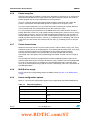
1
Boot loader overview
Boot loader overview
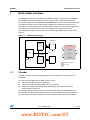
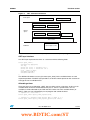
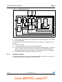
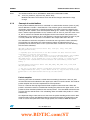
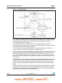
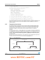
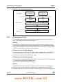
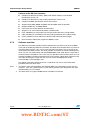
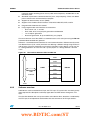
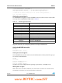
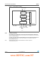
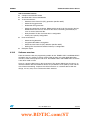
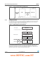
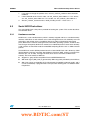
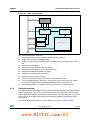
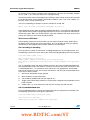
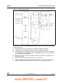
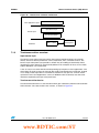
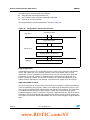
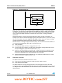
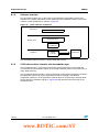
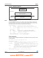
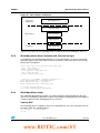
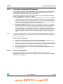
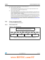
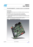
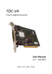
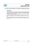
The SPEAr boot process is divided into four different stages. On power-on the BootROM
hard coded in the silicon (eROM) starts (first stage). Its role is to locate XLoader and
transfer the control to it. The BootROM is embedded in the silicon and is not part of the LSP.
The following sections describe the features offered by the components which are not
embedded in the silicon (XLoader and U-Boot) because they are usually board dependent
and need to be customized by the user. These components are part of LSP v2.3.
For a detailed description, please refer to the corresponding SPEAr datasheet and user
manual.
Figure 1.
SPEAr booting stages
D2800000h
NAND/NOR
Shadow
memory
BootROM
X-Loader
eSRAM
ARM
Reset
U-Boot
FFFF0000h
BootROM
Linux/OS
High vectors
Embedded in SPEAr
eROM
1.1
DDR
Part of LSP
XLoader
XLoader is a small firmware loaded during the second stage of the boot phase by the
BootROM.
The main steps performed by XLoader in LSP v2.3 are:
●
Initializing the DDR and PLLs at 333 MHz
●
Passing of board information (DDR size etc.) to U-Boot
●
Loading the U-Boot from NAND, NOR depending on boot type selection and
transferring the control to it.
The XLoader coming with the LSP v2.3 is licensed under GPLv2 and distributed in full
source code. This distributed XLoader version runs on the SPEAr hardware development
kits. You have to customize Xloader to run it on a different PCB, especially the MPMC
Doc ID 16604 Rev 2
www.BDTIC.com/ST
13/245
Boot loader overview
UM0851
settings required for different DDR memory hardware and routing. Please refer to one of the
following application notes for more information on MPMC configuration:
1.1.1
●
AN3100, Configuring the SPEAr3xx multi-port memory controller (MPMC) for external
DDR SDRAM
●
AN3132, Configuring the SPEAr600 multi-port memory controller (MPMC) for external
DDR SDRAM.
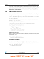
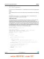
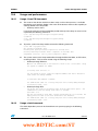
Building XLoader
To build XLoader, you need to use the STLinux toolchain and run the following commands:
/* Build XLoader for SPEAr600 target with DDR@333MHz for size 128MB*/
# make SOC=SPR600 DDRFREQ=333 DDRSIZE=128M
/* Build XLoader for SPEAr300 target with DDR@333MHz for size 128MB*/
# make SOC=SPR300 DDRFREQ=333 DDRSIZE=128M
/* Build XLoader which could be used as a firmware for initializing
* DDR with USB Flashing utility
*/
# make SOC=SPR600 DDRFREQ=166 DDRSIZE=128M CONSOLE=USB
/* Build XLoader for all platform and all types (normal XLoader
* and Flashing utility firmware
*/
# ./makeall
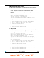
The XLoader source can be compiled with various options, which are listed below:
1.2
●
make SOC=SPR300: This option generates XLoader for the requested platform. Other
platform options can be SPR600, SPR310 and SPR320.
●
make DDRFREQ=333: This option generates XLoader binary image with DDR driver
that supports 333 MHz operation. To generate XLoader for DDR @166 MHZ pass
DDRFREQ=166. This option is available for SPEAr3XX and SPEAr600
●
make DDRSIZE=128M: This option generates XLoader for DDR size of 128 MB. An
other possible parameter can be 64 M to generate 64 MB XLoader.
●
make CONSOLE=USB: This option generates XLoader which is used as a firmware to
initialize DDR in USB flashing utility.
●
make DDRFREQ=333 DDRCONF=ASYNC: This option generates XLoader to
configure DDR @333 MHz asynchronoulsy, for example the DDR is driven through the
clock from PLL2 rather than PLL1 (synchronous operation). This option only works for
DDR @333 MHz. This XLoader can be used with some features of Linux Power
Management (like CPU-Freq) which currently guarantees only the system stability with
asynchronous DDR operation.
U-Boot
Das U-Boot is an open source boot monitor available for a wide range of embedded
processors architectures. A boot monitor is a small piece of software that executes after
powering up an embedded system. It can be used to achieve the following objectives:
14/245
●
Monitor the system for develop/debug purpose
●
Boot an OS
Doc ID 16604 Rev 2
www.BDTIC.com/ST
UM0851
Boot loader overview
Das U-Boot starts from the second sector of Serial NOR Flash, from where it is loaded in
RAM by XLoader.
Note:
In case of NAND it starts from the fifth sector.
Das U-Boot coming with the LSP v2.3 is licensed under GPLv2 and it is distributed in full
source code. This distributed U-Boot version runs on the SPEAr hardware development kits.
1.2.1
U-Boot overview
The U-Boot bootloader is based on U-Boot-1.3.1 release. This U-Boot source supports the
complete SPEAr embedded MPU family (SPEAr600, SPEAr300, SPEAr310 and
SPEAr320). The U-Boot is loaded into DDR2 from NOR (parallel/serial) or NAND memory
device and executed from DDR2. It initializes the following IPs or has the drivers for the
following IPs.
1.2.2
●
UART
●
I2C
●
Ethernet
●
Serial NOR through SMI
●
NAND device through FSMC
●
Parallel NOR (only in SPEAr310)
●
USB Device
Features
U-Boot for SPEAr devices supports the following features:
1.2.3
●
Provides a first level debug environment for on-board testing
●
Supports erasing/writing to NAND/NOR memory devices
●
Supports uploading binary images through Ethernet or Serial port
●
Supports booting the OS (Linux, VxWorks etc)
●
Acts as a firmware for flashing utilities. It supports USB TTY driver.
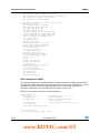
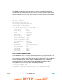
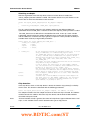
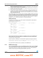
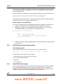
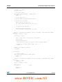
Building U-Boot
To build U-Boot for both serial NOR and NAND Flash, you need to use the STLinux
toolchain and run the following commands:
/* Build U-Boot for SPEAr600 target */
# make spear600_config
Generating include/autoconf.mk
Configuring for spear600 board...
# make
/* Build U-Boot for SPEAr300 target */
# make spear300_config
Generating include/autoconf.mk
Configuring for spear300 board...
# make
/* Build U-Boot for SPEAr310 target */
# make spear310_config
Generating include/autoconf.mk
Configuring for spear310 board...
Doc ID 16604 Rev 2
www.BDTIC.com/ST
15/245
Boot loader overview
UM0851
# make
/* Build U-Boot for SPEAr320 target */
# make spear320_config
Generating include/autoconf.mk
Configuring for spear320 board...
# make
The U-Boot source can be compiled with various options, which are listed below:
1.2.4
●
make CONSOLE=USB: This option generates firmware binary image (containing TTY
over USB driver) to be downloaded for the operation of the Flashing Utility (refer to the
Section 11: Flashing utility section).This option is available for SPEAr3xx and
SPEAr600.
●
make ENV=NAND: This option generates U-Boot/firmware image which saves
environment variables in NAND device. This option is available for SPEAr3xx and
SPEAr600.
●
make FLASH=PNOR: This option generates an image that supports parallel NOR in
place of serial NOR Flash drivers. It is applicable only for SPEAr310.
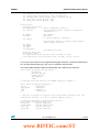
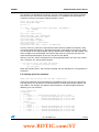
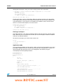
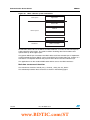
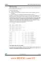
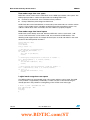
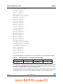
U-Boot commands
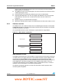
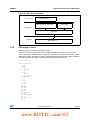
You can display the complete list of U-Boot commands using the 'help' command.
spear600>
?
autoscr base
bdinfo boot
bootd
bootm
bootp
cdp
cmp
coninfo cp
crc32
dhcp
echo
erase
flinfo go
help
i2c
iminfo imls
itest
loadb
loads
loady
loop
md
mm
mtest
mw
nand
nboot
nfs
nm
-
16/245
help
alias for 'help'
run script from memory
print or set address offset
print Board Info structure
boot default, for example, run 'bootcmd'
boot default, for example, run 'bootcmd'
boot application image from memory
boot image via network using BootP/TFTP protocol
Perform CDP network configuration
memory compare
print console devices and information
memory copy
checksum calculation
invoke DHCP client to obtain IP/boot params
echo args to console
erase FLASH memory
print FLASH memory information
start application at address 'addr'
print online help
I2C sub-system
print header information for application image
list all images found in flash
return true/false on integer compare
load binary file over serial line (kermit mode)
load S-Record file over serial line
load binary file over serial line (ymodem mode)
infinite loop on address range
memory display
memory modify (auto-incrementing)
simple RAM test
memory write (fill)
NAND sub-system
boot from NAND device
boot image via network using NFS protocol
memory modify (constant address)
Doc ID 16604 Rev 2
www.BDTIC.com/ST
UM0851
Boot loader overview
ping
- send ICMP ECHO_REQUEST to network host
printenv- print environment variables
protect - enable or disable FLASH write protection
rarpboot- boot image via network using RARP/TFTP protocol
reset
- Perform RESET of the CPU
run
- run commands in an environment variable
saveenv - save environment variables to persistent storage
saves
- save S-Record file over serial line
setenv - set environment variables
setfreq - change ddr/cpu frequency
sleep
- delay execution for some time
tftpboot- boot image via network using TFTP protocol
version - print monitor version
writemac - write mac address in I2C memory
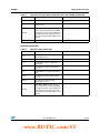
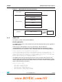
Commands can be grouped into the following categories, according to their function:
Informative commands
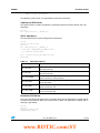
This group of commands is used to get runtime information concerning the system itself. For
example, using the 'bdinfo' command, you can retrieve the XLoader image revision.
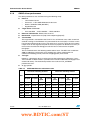
Table 1.
Informative U-Boot commands
Command
Behavior
Example
bdinfo
spear600> bdinfo
arch_number = 0x000008BC
env_t
= 0x00000000
Print board info structure
boot_params = 0x00000100
DRAM bank
= 0x00000000
Along with other things, this structure
-> start
= 0x00000000
also contains
-> size
= 0x08000000
– Frequency at which DDR is operating DDR Freq
= 333
– DDR type (DDR2/DDRMOBILE)
DDR Type
= DDR2
ethaddr
= 55:66:77:88:99:00
– XLoader revision
ip_addr
= 192.168.1.10
baudrate
= 115200 bps
XLoader Rev = XLoader-SPEAr600
help
Print online help
version
Print monitor version
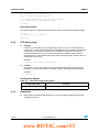
Memory commands
U-Boot offers the possibility to interact with the memory subsystem (RAM, ROM, Flash, …)
using a set of basic commands to move data to/from memory, compare memory locations,
change memory locations and test memory.
Table 2.
Memory U-Boot commands
Command
Behavior
Example
base
Print or set address offset for memory
commands
base 0x1300000
md
Memory display
md 0x1300000
Mm
Memory modify (auto-incrementing)
mm 0x1300000
Doc ID 16604 Rev 2
www.BDTIC.com/ST
17/245
Boot loader overview
Table 2.
UM0851
Memory U-Boot commands (continued)
Command
Behavior
Example
mtest
Simple RAM test
mtest 0x1600000 0x1610000 0xff
Mw
Memory write fill
mw.l 0x1600000 0x55aa55aa 0x100
Nm
Memory modify (constant address)
nm 0x1600000
01600000: 00000000 ? abcdabcd
01600000: abcdabcd ? 12345678
01600000: 12345678 ? 87654321
cmp
Memory compare
cmp.b 0x1300000 0x1600000
0x200000
Cp
Memory copy
cp.b 0x1300000 0x1600000
0x300000
Itest
Return true/false on integer compare
loop
Infinite loop on address range
loop 0x1300000 0x10000
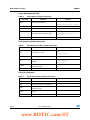
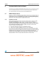
Persistent storage commands
This section describes the U-Boot commands used to access non-volatile storage.
Table 3.
Persistent storage U-Boot commands (I2C, NOR, NAND)
Command
erase
Erase Flash memory
flinfo
Print Flash memory information
Example
erase 0xf8000000 +0x10000
erase 1:0-3
I2C subsystem commands
i2c md 0x50 0x0
0000: 14 15 16 17 18 19 1a 1b 1c
1d 1e 1f 20 21 22 23
............ !"#
iminfo
Print header information for application
image
iminfo 0xf8000000
## Checking Image at f8000000
...
Image Name:
XLoader
Image Type:
ARM Linux
Kernel Image (uncompressed)
Data Size:
4472 Bytes =
4.4 kB
Load Address: d2800b00
Entry Point: d2800b00
Verifying Checksum ... OK
imls
List all images found in NAND/NOR
Flash
nand
NAND command subsystem
nand read.jffs2 0x1300000 0x0
0x10000
Boot from NAND device
nboot.jffs2 0x1300000 0 0x60000
for the image to boot
automatically, an environment
variable “autostart” is to be
set to “yes”
i2c
nboot
18/245
Behavior
Doc ID 16604 Rev 2
www.BDTIC.com/ST
UM0851
Boot loader overview
Table 3.
Persistent storage U-Boot commands (I2C, NOR, NAND) (continued)
Command
Behavior
Example
cmp
Memory compare
cmp.b 0x1300000 0x1600000
0x200000
cp
Memory copy
cp.b 0x1300000 0x1600000
0x300000
writemac 00:99:88:77:66:55
writemac
Write MAC address in I2C memory
This command writes 0x55 and 0xAA
as magic number(to say that MAC id is
present here) at offset 0 and 1 in the
chip and stores the MAC address from
offset 2
protect
Enable or disable Flash write protection protect off 1:0-5
Network commands
Table 4.
Network U-Boot commands
Command
Behavior
Example
bootp
Boot image via network using
BootP/TFTP protocol
cdp
Perform CDP network configuration
dhcp
Invoke DHCP client to obtain IP/boot
parameters
Nfs
Boot image via network using NFS
protocol
ping
Send ICMP echo request to network
host
ping 192.168.1.1
tftpboot
Boot image via network using TFTP
protocol
tftpboot 0x1300000 uImage
rarpboot
Boot image via network using
RARP/TFTP protocol
writemac
Write MAC address in I2C memory
This command writes 0x55 and 0xAA
as magic number(to say that MAC id is
present here) at offset 0 and 1 in the
chip and stores the MAC address from
offset 2
bootp 0x1600000 uImage
writemac 00:99:88:77:66:55
Doc ID 16604 Rev 2
www.BDTIC.com/ST
19/245
Boot loader overview
UM0851
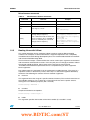
Image booting commands
Table 5.
Image booting U-Boot commands
Command
Behavior
Example
autoscr 0x1600000
Autoscr
Run script from memory
## Executing script at 01300000
Boot
Boot default, for example ‘run bootcmd’
Bootd
Boot default, for example ‘run bootcmd’
Go
Start application at address ‘addr’
Bootm
Boot application image from memory
go 0x1300000
## Starting application at
0x01300000 ...
bootm 0x1600000
Environment variable commands
Table 6.
Environment variables U-Boot commands
Command
Behavior
echo
Echo args to console
printenv
Print environment variables
run
Run commands in an environment
variable
saveenv
Save environment variables to
persistent storage
setenv
Set environment variables
Example
echo abcd
abcd
echo $(bootdelay)
1
echo $(bootcmd)
bootm 0xf8050000
run bootcmd
Serial i/f commands
Table 7.
Serial i/f file loading U-Boot commands
Command
20/245
Behavior
Example
coninfo
Print console devices ad information
Coninfo
loads
Load S-record file over serial line
loads 0x1300000
loady
Load binary file over serial line
(ymodem mode)
loady 0x1300000
loadb
Load binary file over serial line (kermit
mode)
loadb 0x1300000
saves
Save S-Record file over serial line
Doc ID 16604 Rev 2
www.BDTIC.com/ST
UM0851
Boot loader overview
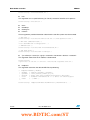
Miscellaneous commands
Table 8.
Miscellaneous U-Boot commands
Command
Example
reset
Resets the CPU
crc32
Crc32 checksum calculation
crc32 0x1300000 0x10000
echo
Echo args to console
echo abcd
abcd
echo $(bootdelay)
1
setfreq
Change ddr/cpu frequency
This command actually assumes that
CPU is running on PLL1 and DDR on
PLL2. So, effectively, this command
changes PLL1/2 frequency
setfreq cpu 300
CPU frequency changed
(This changes the PLL1
to 300 MHz)
setfreq ddr 300
DDR frequency changed
(This changes the PLL1
to 300 MHz)
sleep
1.2.5
Behavior
to 300
frequency
to 300
frequency
Delay execution for some time
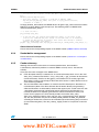
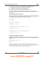
Booting Linux with U-Boot
This section describes how to configure U-Boot in order to achieve different booting
schemes. For example, in some environments it might be required to have a completely
standalone board, while during development phase it is recommended to boot from network
and to mount RootFS through NFS.
The Linux kernel accepts a command line that can be used to pass arguments to the kernel
and to overwrite statically built-in values. In this way the you can change parameters without
the need to rebuild the kernel. Please refer to the Linux kernel source tree file
'Linux/Documentation/kernel-parameters.txt' for a complete listing of all the supported
kernel arguments.
Das U-Boot stores the argument list in the environment variable bootargs. The syntax is a
sequence of items in the form key=value, where key is a well known argument defined by
the kernel. The following list contains the most common arguments:
●
mem=nn
This argument forces the usage of a specific amount of memory. This can be the total size of
the available memory or just a subset of it. Linux will make use of this specific amount,
leaving the rest to different purposes (like a 2nd OS).
setenv bootargs "mem=128M …"
●
console=
Output console device and options.
setenv bootargs "console=ttyS0 …"
●
initrd=
This argument specifies the location of the initial ramdisk (if a ramdisk is used).
Doc ID 16604 Rev 2
www.BDTIC.com/ST
21/245
Boot loader overview
UM0851
setenv bootargs "initrd=0x00800040,7M …"
●
init=
This argument runs a specified binary (ex: /bin/sh) instead of /sbin/init as init process.
setenv bootargs "init=/bin/sh …"
●
root=
●
rootdelay=
●
rootfstype=
●
nfsroot=
These arguments provide information about how the root file system must be mounted.
/* NFS mount */
setenv bootargs "root=/dev/nfs nfsroot=192.168.1.1:/home/spear600/rootfs …"
/* MTD mount (NAND/NOR flash) */
"root=/dev/mtdblock3 rootfstype=jffs2 ..."
/* RAMDisk mount */
setenv bootargs "root=/dev/ram0 initrd=0x00800040,7M …"
/* USB flash mount */
setenv bootargs "root=/dev/sda1 rootdelay=5 …"
●
"ip=<client-ip>:<server-ip>:<gw-ip>:<netmask>:<hostname>:<device>:<autoconf>
This argument shows how the IP address is determined.
setenv bootargs
"ip=192.168.1.13:192.168.1.1:192.168.1.1:255.255.255.0:spear600:eth0:off …"
●
mtdparts=
This argument overwrites the default MTD Flash partitioning.
/*
*
*
*
*
*
*/
mtdparts=<mtddef>[;<mtddef]
<mtddef> := <mtd-id>:<partdef>[,<partdef>]
<partdef> := <size>[@offset][<name>][ro][lk]
<mtd-id> := unique name used in mapping driver/device (mtd->name)
<size>
:= standard linux memsize OR "-" to denote all remaining space
<name>
:= '(' NAME ')'
setenv bootargs
22/245
"mtdparts=SMI-NOR0:2M(PARTITION-1),3M(PARTITION-2)... "
Doc ID 16604 Rev 2
www.BDTIC.com/ST
UM0851
2
Linux OS and device driver general information
Linux OS and device driver general information
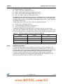
Linux coming with the LSP v2.3, which is based on kernel version 2.6.27, is licensed under
GPLv2 and distributed in full source code.
LSP v2.3 supports the following features of Linux:
●
Patch for YAFFS file system support over NAND
●
Support for high resolution timer
●
All drivers integrated into standard Linux device model
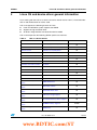
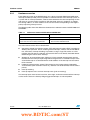
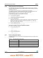
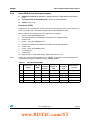
LSP v2.3 incorporates the following SPEAr specific set of drivers:
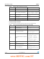
Table 9.
LSP v2.3 device drivers
Section name
Driver name
SPEAr MPU
Platform section
General purpose timer (GPT) driver
All
Platform section
Vector interrupt controller (VIC) driver
All
Platform section
Real time clock (RTC) driver
All
Communication device drivers
GMAC Ethernet driver
All
Communication device drivers
MACB (MAC block) driver
Communication device drivers
USB Host
All
Communication device drivers
USB Device
All
Communication device drivers
I2C driver
All
Communication device drivers
SPI driver
All
Communication device drivers
SDIO driver
SP300, SP320
Communication device drivers
UART driver
All
Communication device drivers
CAN driver
SP320
Communication device drivers
HDLC driver
SP310
Non-volatile memory device
drivers
NAND Flash driver
All
Non-volatile memory device
drivers
EMI interface driver
All
Non-volatile memory device
drivers
Serial NOR Flash driver
All
Non-volatile memory device
drivers
USB mass storage support
All
Non-volatile memory device
drivers
I2C and SPI memory device support
All
Non-volatile memory device
drivers
SD/MMC memory supportt
Accelerator engine device
drivers
JPEG driver
SP310, SP320
Doc ID 16604 Rev 2
www.BDTIC.com/ST
SP300
All
23/245
Linux OS and device driver general information
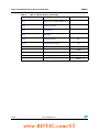
Table 9.
LSP v2.3 device drivers (continued)
Section name
24/245
UM0851
Driver name
SPEAr MPU
Accelerator engine device
drivers
General purpose DMA (DMAC) driver
All
Human interface device (HID)
drivers
Touchscreen driver
All
Human interface device (HID)
drivers
Keypad driver
Human interface device (HID)
drivers
ADC driver
All
Human interface device (HID)
drivers
LCD panel support
All
Human interface device (HID)
drivers
USB HID Class Support
All
Audio/video drivers
LCD controller (CLCD) driver
Audio/video drivers
TDM driver
Miscellaneous device drivers
General purpose I/O (GPIO) driver
All
Miscellaneous device drivers
Watchdog (WDT) driver
All
Miscellaneous device drivers
Pulse width modulator (PWM) driver
SP300
SP600,SP300
Doc ID 16604 Rev 2
www.BDTIC.com/ST
SP300
SP320
UM0851
3
Platform section
Platform section
This section describes the basic SPEAr platform code and driver. It consists of the following
directories:
●
arch/arm/plat-spear
●
arch/arm/mach-spear600
●
arch/arm/mach-spear300
The platform code has been split in this way so that common code across SPEAr platforms
is kept in the plat-spear/ directory and platform specific code is kept in the respective machspear600/ (or mach-spear300/ directory for all SPEAr3xx).
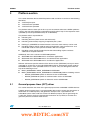
The platform code is responsible for:
●
Initializing VIC
●
Initializing the timer (clock source and clock event)
●
Initializing static memory mapping if required by the system
●
Defining IO_ADDRESS and related macros so that the static memory can be used
●
Providing platform specific code for power management, clock framework etc. and
initialization code for some specific controllers like fsmc and gpio
●
Providing system specific header files like those describing irq lines and base
addresses of respective devices
Additionally, there are 3 variants for SPEAr300 platform.
●
SPEAr300: Basic SPEAr300 with IPs for telecom applications
●
SPEAr310: Basic SPEAr300 with IPs for communication applications
●
SPEAr320: Basic SPEAr300 with IPs for industrial applications
Different architecture specific code for all the above variants (SPEAr3xx) are kept in machspear300/ as all of these are basically SPEAr300 machines. Architecture specific code for
SPEAr600 is kept in mach-spear600/ and has no variant. They are distinguished with the
help of the following macros:
3.1
●
MACH_SPEAR600 or ARCH_SPEAR600 for SPEAr600
●
MACH_SPEAR300 or ARCH_SPEAR300 for all SPEAr300 platforms including variants
–
BOARD_SPEAR300 specific for telecom version of SPEAr300
–
BOARD_SPEAR310 specific for communication version of SPEAr300
–
BOARD_SPEAR320 specific for industrial version of SPEAr300
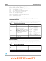
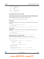
General purpose timer (GPT) driver
This section describes the driver of the general purpose timer embedded in SPEAr devices.
A digital general purpose timer is a programmable device with a counter that increments or
decrements at a fixed frequency and generates interrupts after a specified time. An
embedded system makes wide use of timers for different purpose, like for generating the
system-tick, which is the basic temporization mechanism of any RTOS, or for other fine
granularity time measurement mechanisms.
Doc ID 16604 Rev 2
www.BDTIC.com/ST
25/245
Platform section
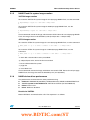
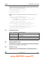
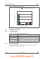
3.1.1
UM0851
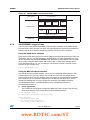
Hardware overview
SPEAr provides several GPTs acting as APB slaves. Each GPT consists of 2 independent
channels, each one made of a programmable 16-bit counter and a dedicated 8-bit timer
clock prescaler. The programmable 8-bit prescaler performs a clock division from 1 to 256.
Different input frequencies can be defined using SPEAr configuration registers.
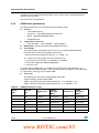
The main features of the GPT module are listed below:
●
Each timer module provides two independent channels with separate control, count,
clock prescaler and interrupt registers
●
Each channel has 16-bit counter with a programmable timer interval
●
Provides auto-reload or single-shot mode feature
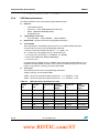
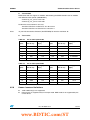
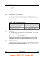
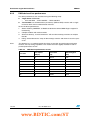
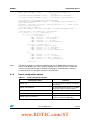
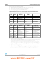
The following table shows GPTs available on different SPEAr platforms:
Table 10.
GPTs available on SPEAr
SPEAr600
SPEAr3xx
1 GPT in each CPU subsystem
2 in application subsystem
1 in basic subsystem
1 GPT in CPU subsystem
2 in basic subsystem
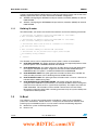
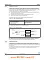
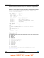
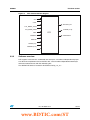
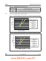
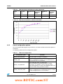
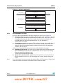
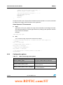
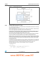
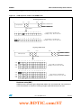
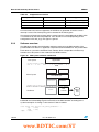
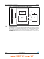
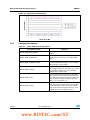
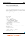
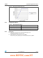
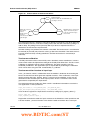
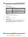
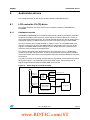
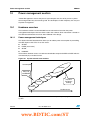
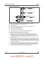
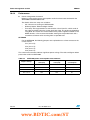
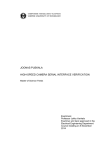
The following figure describes the GPT hardware interface.
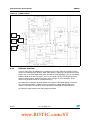
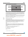
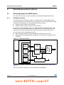
Figure 2.
GPT hardware interface
0,,
SYNTHESIZER
'04#HANNEL
-ATCH?)NT
'04#HANNEL
-ATCH?)NT
0,,
-(Z
!0"INTERFACE
The TIMER_CLK can be selected between a fixed 48 MHz source and PLL1, which is also
the source for the rest of the system. The PLL1 output also goes through a synthesizer
which can be programmed to derive the actual required operating GPT clock.
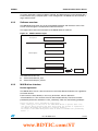
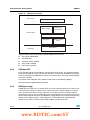
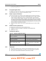
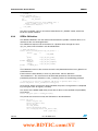
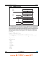
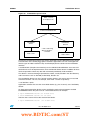
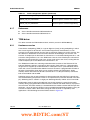
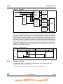
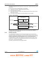
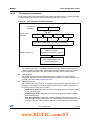
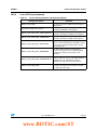
3.1.2
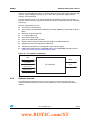
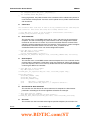
Software overview
SPEAr LSP provides proprietary software routines to allocate, program and use the general
purpose timer. This set of routines abstract the GPT hardware block and provide easy
kernel APIs to manage and control these timers. This layer does not provide any interface to
the user space.
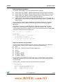
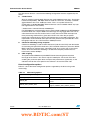
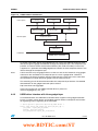
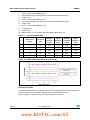
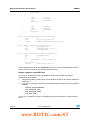
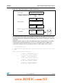
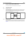
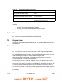
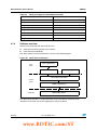
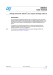
The following figure explains the GPT framework as used by the kernel time keeping and
tick management subsystem. The GPT routines can also be directly used by user
modules/applications.
26/245
Doc ID 16604 Rev 2
www.BDTIC.com/ST
UM0851
Platform section
Figure 3.
GPT software architecture
5SERSPACE
$ATESLEEP
4IMEMANAGEMENT
5SERAPPLICATIONS
4IMEOFDAYKEEPING
+ERNEL
SPACE
#LOCKSOURCE
#LOCKEVENT
5SERMODULES
'04ROUTINES
(ARDWARE
'ENERALPURPOSETIMER
In the Linux source tree, the GPT layer is present in arch/arm/plat-spear/gpt.c
GPT layer interface
The GPT layer represents the timer as a structure with the following fields.
struct spear_timer {
unsigned long phys_base;
int irq;
struct clk *iclk; /* interface clk */
struct clk *fclk; /* functional clk */
void __iomem *io_base;
unsigned reserved:1;
unsigned enabled:1;
};
The SPEAr LSP defines an array (of struct spear_timer) for the available timers on each
respective platform. The GPT layer provides a set of APIs which operate on this structure to
manage the set of available timers.
Allocating a timer
There are two ways of allocating a GPT. You can either ask for a free timer, in this case an
available timer on the list will be allocated to you, or, ask for a specific timer, so if it is
available, it will be allocated to you. Both the APIs return one of the available timers (or
NULL), which you can subsequently use to program and control the timer.
/* request for a free timer */
struct spear_timer *spear_timer_request(void);
/* request for a specific timer greater than or equal to 1 */
struct spear_timer *spear_timer_request_specific(int timer);
Doc ID 16604 Rev 2
www.BDTIC.com/ST
27/245
Platform section
UM0851
Setting the source clock
There are two possible clock sources for each timer block. One source can be directly from
PLL3 (constant 48 MHz) and the other can be from PLL1 through synthesizer. Either of
these source clocks can be selected by the following API.
Note:
1
The selection of the source clock applies to the whole timer hardware block thus affecting
both channels.
2
When the PLL1 (system) clock is selected as the timer clock, any change in the system
clock for power saving, etc. has an impact on the frequency of the GPT. In such cases, you
must always get the current clock rate for programming next GPT interrupt. Please refer to
clock framework chapter for information on clock framework usage.
3
The use of 48 MHz (PLL3) is discouraged as it leads to unpredictable results in reading
counter value. Please refer to the GPT application note for details.
/* set the appropriate clock src
source can be:
SPEAR_TIMER_SRC_SYS_CLK,from PLL1
SPEAR_TIMER_SRC_PLL3_CLK,from PLL3
*/
void spear_timer_set_source(struct spear_timer *timer, int source);
Programming the prescaler
After configuring the appropriate clock source, you can program the prescaler. The
prescaler can be different for each timer channel (within a hardware block) and can range
from 1 to 256 in 8 levels.
/* set the appropriate prescaler
prescaler can be
GPT_CTRL_PRESCALER1 0x0
GPT_CTRL_PRESCALER2 0x1
GPT_CTRL_PRESCALER4 0x2
GPT_CTRL_PRESCALER8 0x3
GPT_CTRL_PRESCALER16 0x4
GPT_CTRL_PRESCALER32 0x5
GPT_CTRL_PRESCALER64 0x6
GPT_CTRL_PRESCALER128 0x7
GPT_CTRL_PRESCALER256 0x8
*/
spear_timer_set_prescaler( struct *spear_timer, int prescaler);
GPT interrupt management
Each timer channel of a hardware block of GPT has separate independent interrupt lines.
You can use the following API to know which interrupt line is associated with the timer. Then
using Linux calls, you can attach an interrupt handler to these irq lines. You can use
separate APIs to enable and clear the interrupts for a timer.
/* This shall return the irq associated with timer */
int spear_timer_get_irq(struct spear_timer *timer);
/* Enable/Disable the timer match interrupt */
void spear_timer_set_match(struct spear_timer *timer, int enable);
28/245
Doc ID 16604 Rev 2
www.BDTIC.com/ST
UM0851
Platform section
/* Clear the match interrupt status
value must be GPT_STATUS_MATCH
*/
void spear_timer_write_status(struct spear_timer *timer, u16 value)
GPT operation
The following APIs can be used to start/stop the GPT timer in single-shot or auto-reload
mode.
/* This shall load the timer with "load" count value and start the timer */
void spear_timer_set_load_start(struct spear_timer *timer, int autoreload, u16
load);
/* These APIs separately load, start and stop the timer */
void spear_timer_set_load(struct spear_timer *timer, int autoreload, u16 load);
void spear_timer_start(struct spear_timer *timer);
void spear_timer_stop(struct spear_timer *timer);
GPT counter value
The 16-bit GPT counter value can be read any time through the following API. Please note
that in case of an asynchronous operation, when the GPT runs on PLL3 and AHB is fed by
PLL1, due to different clock domains, the value reported by this API may not be valid.
Please refer to the GPT application note for more details on this.
/* This shall return the count value of the timer */
unsigned int spear_timer_read_counter(struct spear_timer *timer);
3.1.3
GPT driver usage
Two of these timers are used by the clock keeping and event generation framework of Linux
to maintain Linux time and generation of timer tick. They are defined using the GPT APIs to
configure, program and use the hardware timers. For details please refer to arch/arm/platspear/time.c.
Clock source
One of the GPT timers acts as a free running timer used by Linux to maintain the time of
day. The clock source for Linux is a monotonic increasing timer used by the kernel to get
timer value at any time. For this, it needs to provide a callback to the kernel
(clocksource_read_cycles()) for reading the count value.
static cycle_t clocksource_read_cycles(void)
{
return (cycle_t)spear_timer_read_counter(clk_clksrc_tmr);
}
struct clocksource clocksource_gpt = {
.name
= "clock source",
.rating = 200,
.read
= clocksource_read_cycles,
.mask
= 0xFFFF,
/* 16 bits */
.mult
= 0,
/* to be computed */
.shift = 20,
.flags = CLOCK_SOURCE_IS_CONTINUOUS,
};
void hrt_clocksource_init(void)
{
Doc ID 16604 Rev 2
www.BDTIC.com/ST
29/245
Platform section
UM0851
static struct spear_timer *gpt;
u32 tick_rate;
gpt = spear_timer_request_specific(2);
BUG_ON(gpt == NULL);
spear_timer_set_source(gpt, SPEAR_TIMER_SRC_SYS_CLK);
/* initialize other fields ot clocksource structure */
...
/* load the counter, start timer */
spear_timer_set_load_start(gpt, 1, 0xFFFF);
/* register the clocksource */
clocksource_register (&clocksource_gpt);
}
Clock event
This entity is used by the kernel to program the next tick event. Normally this happens every
10 msec (CLOCK_EVT_MODE_PERIODIC). In tickless and high resolution timers, it can be
used by the kernel to program the tick at the next suitable interval (even if it is longer than
than 10 msec). For that it uses two callbacks, set_mode() and set_next_event().
static struct clock_event_device clockevent_gpt = {
.name
= "clock_event",
.features
= CLOCK_EVT_FEAT_PERIODIC | CLOCK_EVT_FEAT_ONESHOT,
.set_mode
= clockevent_set_mode,
.set_next_event= clockevent_next_event,
.shift
= 32,
};
static void clockevent_set_mode(enum clock_event_mode mode,
struct clock_event_device* clk_event_dev )
{
u32 period;
spear_timer_stop(clk_event_tmr);
/* clear interrupt */
spear_timer_write_status(clk_event_tmr, GPT_STATUS_MATCH);
switch(mode) {
case CLOCK_EVT_MODE_PERIODIC:
/* calculate period for 10 msec timer */
...
/* program timer for 10 msec tic Enable interrupt */
spear_timer_set_match(clk_event_tmr, 1);
spear_timer_set_load_start(clk_event_tmr, 1, period);
break;
case CLOCK_EVT_MODE_ONESHOT:
/*
* timer to be programmed for one shot, the actual programming
* period to be passed in program next event function
*/
break;
case CLOCK_EVT_MODE_UNUSED:
case CLOCK_EVT_MODE_SHUTDOWN:
case CLOCK_EVT_MODE_RESUME:
break;
30/245
Doc ID 16604 Rev 2
www.BDTIC.com/ST
UM0851
Platform section
default:
printk("XXX: set_mode=Error!!!\n");
break;
}
}
static int clockevent_next_event(unsigned long cycles,
struct clock_event_device* clk_event_dev )
{
spear_timer_set_load_start(clk_event_tmr, 0, (u16)cycles);
return 0;
}
static void __init hrt_clockevent_init(void)
{
u32 tick_rate;
clk_event_tmr = spear_timer_request_specific(1);
BUG_ON(clk_event_tmr == NULL);
/*
* program other parameters
* set clock source, program pre-scaler
*/
clockevent_gpt.mult = div_sc(tick_rate, NSEC_PER_SEC,
clockevent_gpt.shift);
clockevent_gpt.max_delta_ns =
clockevent_delta2ns(0xffff, &clockevent_gpt);
clockevent_gpt.min_delta_ns =
clockevent_delta2ns(1, &clockevent_gpt);
clockevent_gpt.cpumask = cpumask_of_cpu(0);
clockevents_register_device(&clockevent_gpt);
spear_timer_irq.dev_id = (void *)clk_event_tmr;
setup_irq(spear_timer_get_irq(clk_event_tmr), &spear_timer_irq);
spear_timer_set_match(clk_event_tmr, 1);
}
Configuration options
As mentioned above, the GPT hardware clock can be obtained from two sources (the
system clock PLL1 and PLL3). The system clock, if selected, goes through a synthesizer
before reaching GPT. This synthesizer can be programmed to obtain the desired operating
frequency for GPT. By default it is divided by 2. For more details, please refer to the SPEAr
user manual.
References
●
3.2
Refer to linux-2.6.27/Documentation/timers/, for new time keeping and tick generation
architecture of Linux.
Vector interrupt controller (VIC) driver
This section describes the VIC driver.
Doc ID 16604 Rev 2
www.BDTIC.com/ST
31/245
Platform section
3.2.1
UM0851
Hardware overview
Each ARM subsystem of the SPEAR family has a Daisy-Chained ARM PrimeCell® vector
interrupt controller (PL190). The VIC provides a software interface to the interrupt system. In
a system with an interrupt controller, software must determine the source requesting service
and where its service routine is loaded. A VIC does both of these in hardware. It supplies
the starting address, or vector address of the service routine corresponding to the highest
priority requesting interrupt source.
The following table shows the differences between the hardware features for SPEAr600 and
SPEAr300.
Table 11.
Differences between SPEAr600 and SPEAr300
SPEAr600
SPEAr300
– Two daisy chained ARM PrimeCells
– One ARM PrimeCell
– A total of 64 interrupt lines are available for
each CPU from its two daisy-chained ICs.
– A total of 32 interrupt lines are available for the
CPU from the ARM PrimeCell.
The main features of the VIC are listed below:
●
Generation of both fast interrupt request (FIQ) and interrupt request (IRQ), according to
ARM system operation. IRQ is used for general interrupts, whereas FIQ is intended for
fast, low-latency interrupt handling. In particular, using a single FIQ source at a time
provides interrupt latency reduction, because the ISR can be directly executed without
determining the source of the interrupt.
●
Support for 16 vectored interrupts (IRQ only). Each vectored interrupt block receives
the IRQ from the interrupt request logic block and generates a vectored interrupt. Each
vectored interrupt is associated with the 32-bit address of the interrupt service routine
to be executed.
●
Hardware interrupt priority, where FIQ interrupt has the highest priority, followed by
vectored IRQs (from vector 0 to vector 15), and then non-vectored IRQs with the lowest
priority.
●
Interrupt masking
●
Interrupt request status and raw interrupt status (prior to masking).
The interrupt inputs must be level sensitive, active high, and held asserted until the interrupt
service routine clears the interrupt. Edge-triggered interrupts are not compatible.
32/245
Doc ID 16604 Rev 2
www.BDTIC.com/ST
UM0851
Figure 4.
Platform section
VIC block diagram
VICINTSOURCE[31:0]
Interrupt
request
logic
FIQSTATUS[31:0]
Non-vectored FIQ
interrupt logic
IRQSTATUS[31:0]
Non-vectored IRQ
interrupt logic
Vectored interrupt 0
IRQ0
VectAddr0
Vectored interrupt 1
IRQ1
VectAddr1
nVICFIQ
IRQn
VectAddrn
Vectored interrupt 15
nVICIRQIN
VICVECTADDRIN
IRQ15
VectAddr15
nVICIRQ
IRQ
VectAddrin
VICVECTADDROUT
nVICFIQIN
VectAddrOut
HCLK
HSELVIC
HTRANS
HADDR[11:2]
HRESETn
HWRITE
HREADYIN
IRQ vector
address and
priority logic
AHB slave interface
HRDATA[31:0]
HWDATA[31:0]
HREADYOUT
HSIZE[2:0]
HRESP[1:0}
HPROT
Control logic
3.2.2
Software overview
Linux provides the generic interrupt handling layer which contributes to the complete
abstraction of interrupt handling for device drivers. It is able to handle all the different types
of interrupt controller hardware. Device drivers use generic API functions to request, enable,
disable and free interrupts. The drivers do not have to know anything about interrupt
hardware details, so they can be used on different platforms without code changes.
At Linux level there are three main levels of abstraction in the interrupt code:
●
High level driver API
●
High level IRQ flow handlers
●
Chip level hardware encapsulation
Interrupt control flow
Each interrupt is described by an interrupt descriptor struct irq_desc. The interrupt is
referenced by an 'unsigned int' numeric value which selects the corresponding interrupt
Doc ID 16604 Rev 2
www.BDTIC.com/ST
33/245
Platform section
UM0851
description structure in the descriptor structures array. The descriptor structure contains
status information and pointers to the interrupt flow method and the interrupt chip structure
which are assigned to this interrupt.
Whenever an interrupt triggers, the low level arch code calls into the generic interrupt code
by calling desc->handle_irq(). This high level IRQ handling function only uses desc->chip
primitives referenced by the assigned chip descriptor structure. The details of these
primitives are covered in later sections.
struct irq_desc {
irq_flow_handler_t
handle_irq;
struct irq_chip
*chip;
struct msi_desc
*msi_desc;
void
*handler_data;
void
*chip_data;
struct irqaction
*action;/* IRQ action list */
unsigned int
status;/* IRQ status */
unsigned int
depth;/* nested irq disables */
unsigned int
wake_depth;/* nested wake enables */
unsigned int
irq_count;/* For detecting broken
IRQs */
unsigned int
irqs_unhandled;
unsigned long
last_unhandled;/* Aging timer for unhandled count */
spinlock_t
lock;
#ifdef CONFIG_SMP
cpumask_t
affinity;
unsigned int
cpu;
#endif
#if defined(CONFIG_GENERIC_PENDING_IRQ) || defined(CONFIG_IRQBALANCE)
cpumask_t
pending_mask;
#endif
#ifdef CONFIG_PROC_FS
struct proc_dir_entry*dir;
#endif
const char
*name;
}
High level driver API
The high level driver API normally used in device drivers consists of the following functions:
●
request_irq()
●
free_irq()
●
disable_irq()
●
enable_irq()
●
disable_irq_nosync() (SMP only)
●
synchronize_irq() (SMP only)
●
set_irq_type()
●
set_irq_wake()
●
set_irq_data()
●
set_irq_chip()
●
set_irq_chip_data()
The details of some of the most important APIs described above are covered in
Section 3.2.5: VIC usage.
34/245
Doc ID 16604 Rev 2
www.BDTIC.com/ST
UM0851
Platform section
High level IRQ flow handlers
The generic layer provides a set of pre-defined IRQ-flow methods:
●
handle_level_irq(): provides a generic implementation for level-triggered interrupts
●
handle_edge_irq(): provides a generic implementation for edge-triggered interrupts
●
handle_simple_irq(): provides a generic implementation for simple interrupts. The
simple flow handler does not call any handler/chip primitives
●
handle_percpu_irq(): provides a generic implementation for per CPU interrupts. Per
CPU interrupts are only available on SMP and the handler provides a simplified version
without locking.
The interrupt flow handlers (either predefined or architecture-specific) are assigned to
specific interrupts by the architecture either during the boot up or during the device
initialization.
In the SPEAr architecture, at boot up time, the architecture specific code sets up the
handle_level_irq flow method as the default for all the VIC interrupts. This is done in
<arch/arm/mach-spearxxx/irq.c>. Below is a part of the code captured from the SPEAr300
architecture-related initialization code for VIC.
void __init spear3xx_init_irq(void)
{
unsigned int i;
do_init_irq(1);
for (i = IRQ_VIC_START; i <= IRQ_VIC_END; i++)
set_irq_chip(i, &vic_chip);
set_irq_handler(i, handle_level_irq);
set_irq_flags(i, IRQF_VALID | IRQF_PROBE);
}
}
{
Chip level hardware encapsulation
The chip level hardware descriptor structure structs irq_chip contains all the direct chip
relevant functions, which can be utilized by the IRQ flow implementations.
●
ack()
●
mask_ack() - optional, recommended for performance
●
mask()
●
unmask()
●
retrigger() - optional
●
set_type() - optional
●
set_wake() - optional
These primitives mean exactly what their name says: ack means ACK, masking means
masking of an IRQ line, etc. It is up to the flow handler(s) to use these basic units of lowlevel functionality.
struct irq_chip is a hardware interrupt chip descriptor described below:
struct irq_chip {
const char*name;
unsigned int(*startup)(unsigned int irq);
void
(*shutdown)(unsigned int irq);
void
(*enable)(unsigned int irq);
void
(*disable)(unsigned int irq);
Doc ID 16604 Rev 2
www.BDTIC.com/ST
35/245
Platform section
UM0851
void
(*ack)(unsigned int irq);
void
(*mask)(unsigned int irq);
void
(*mask_ack)(unsigned int irq);
void
(*unmask)(unsigned int irq);
void
(*eoi)(unsigned int irq);
void
(*end)(unsigned int irq);
void
(*set_affinity)(unsigned int irq, cpumask_t dest);
int
(*retrigger)(unsigned int irq);
int
(*set_type)(unsigned int irq, unsigned int flow_type);
int
(*set_wake)(unsigned int irq, unsigned int on);
* Currently used only by UML, might disappear one day.*/
#ifdef CONFIG_IRQ_RELEASE_METHOD
void (*release)(unsigned int irq, void *dev_id);
#endif
/*
* For compatibility, ->typename is copied into>name.Will disappear.*/
sconst char*typename;
};
3.2.3
VIC API : high level IRQ flow handlers in SPEAR
In the SPEAr architecture code, the setup for the chip level hardware encapsulation is done
at the boot up time. The basic primitives provided are ack/ mask/ unmask/ set_wake. You
can see the code at arch/arm/mach-spearxxx/irq.c.
For each interrupt triggered, these functions provide the interrupt handling at the VIC level,
and handle the VIC specific settings in the registers for the Acknowledgement/ Masking/ Un
Masking / Setting up the Wake up sources at the VIC level.
static struct irq_chip vic_chip = {
.name
= "spear-vic",
.ack
= vic_mask_irq,
.mask
= vic_mask_irq,
.unmask = vic_unmask_irq,
.set_wake = vic_set_wake
};
3.2.4
The internals of interrupt handling in ARM
The function start_kernel( ) is the first 'C' function in Linux, executed when the kernel boots
up. It initializes various subsystems of the kernel, including the IRQ system.
The initialization of IRQ requires that a valid vector table and first level interrupt handlers are
in place, both of these are architecture-specific. start_kernel( ) calls a function called
__trap_init( ) to setup the exception vector table at location 0xffff0000. The vector table and
vector stub code for ARM resides in the <arch/arm/kernel/entry-armv.S> file. The
__trap_init( ) function copies the vector table at location 0xffff0000 and the exception
handlers at 0xffff0200. Keep in mind that the addresses mentioned here are virtual.
After setting up the vector tables start_kernel ( ) calls init_IRQ() to set up the kernel IRQ
handling infrastructure. The function init_irq() calls init_arch_irq( ), here the architecturespecific code of SPEAR does the basic initializations for the VIC at kernel level. The
spearxxx_init_irq() function is defined in arch/arm/mach-spearxxx/irq.c.
When a IRQ is raised, ARM stops what it is processing (assuming it is not processing a
FIQ!), disables further IRQs, puts CPSR in SPSR, puts current PC to LR and switches to
IRQ mode. Then, it refers to the vector table and jumps to the exception handler, which in
our case is __irq_svc(). The function __irq_svc() saves r0-12 on the SVC mode stack (the
36/245
Doc ID 16604 Rev 2
www.BDTIC.com/ST
UM0851
Platform section
kernel stack of the process which was interrupted), reads LR and SPSR from a temporary
IRQ stack and saves them on the SVC mode stack. It increments the preempt count and
calls get_irqnr_and_base() to find out the IRQ line number.
The SPEAr architecture provides the get_irqnr_and_base (arch/arm/machspearxxx/include/mach/entry-macro.S) function to query the interrupt controller to find out
which IRQ line raised this interrupt.
After this, __irq_svc() calls asm_do_IRQ() which in turn calls the IRQ handler (the interrupt
handler that you registered through request_irq ( )) or a default IRQ handler registered by
default during boot time.
After the completion of these actions, the IRQ line for which the interrupt was raised is
unmasked and do_level_irq() returns. After this interrupt handling is complete __irq_svc ()
restores the state of the interrupted process.
So now the IRQ infrastructure is in place, and various modules can register their IRQ
handlers through request_irq(). When you call request_irq( ), the kernel appends your IRQ
handler to the list of all the IRQ handlers registered for that particular IRQ line. It does not
change the exception vector table.
As described above, the Linux implementation for interrupt handling is not a vectored
approach, hence it does not utilize the vector interrupt capabilities provided by the VIC
hardware.
3.2.5
VIC usage
The current implementation in Linux does not allow the exploitation of the complete
capabilities of the VIC. Within the current capabilities that have been added in the Linux,
you can use the VIC in the following ways.
If a driver needs to register a specific interrupt handler, the following call is provided by
Linux:
/*The following functions declared in <linux/interrupt.h> implement the interrupt
registration interface and is use to register the interrupt handler.*/
int request_irq(unsigned int irq, irqreturn_t (*handler)( ), unsigned long flags,
const char *dev_name, void *dev_id);
/* The details of the above fields are as follow:
irq: interrupt number being requested
(*handler)(): pointer to the handler being installed
in driver.
flags: Options related to interrupt management.
*dev_name: string passed here is used in /proc/interrupts to show the owner of
interrupts
*dev_id: Pointer used for shared interrupt lines
*/
/* The function below is use to unregister the interrupt handler. */
void free_irq(unsigned int irq, void *dev_id);
To check for the interrupt sources being used in the system, type in the following command.
$cat
16:
18:
20:
/proc/interrupts
CPU0
3903
spear-vic
0
spear-vic
0
spear-vic
gp_timer
<NULL>
spear-jpeg
Doc ID 16604 Rev 2
www.BDTIC.com/ST
37/245
Platform section
UM0851
24:
26:
27:
28:
36:
37:
42:
44:
50:
51:
57:
58:
59:
60:
61:
Err:
244
0
0
0
0
0
1
29164
0
0
0
3
102
1
0
0
Table 12.
spear-vic
spear-vic
spear-vic
spear-vic
spear-vic
spear-vic
spear-vic
spear-vic
spear-vic
spear-vic
spear-vic
spear-vic
spear-vic
spear-vic
spear-vic
uart-pl011
spear-ssp.0
spear-ssp.1
spear-i2c
<NULL>
spear-ssp.2
spear-dmac
spear-snor
rtc0
<NULL>
spear-udc
ohci_hcd:usb3
ehci_hcd:usb1
ohci_hcd:usb4
ehci_hcd:usb2
Format of interrupt source list
IRQ No
44
No of interrupts
29164
Interrupt string passed in request_irq
spear-snor
3.3
Real time clock (RTC) driver
3.3.1
Hardware overview
The Real-time clocks (RTC) is used to keep track of days, dates and time, including
century, year, month, hour, minutes and seconds. It supports the use of a battery switchover
circuit, enabling it to keep track of time even when power is off.
Features:
38/245
●
Time-of-day clock in 24 hours mode
●
Calendar
●
Alarm capability
●
Self-isolation mode, which allows RTC to work even with no power supplied at the rest
of the device.
Doc ID 16604 Rev 2
www.BDTIC.com/ST
UM0851
Platform section
Figure 5.
RTC functional block diagram
CLK
C32K
OSCI32B_EN
TST_MODE_SCAN
TST_MODE_IDDQ
PSEL
PCDATA (31:0)
RTC
INTERRUPT
PENABLE
RWRITE
PADDR (4:2)
PWDATA (31:0)
3.3.2
Software overview
RTC support in the kernel is architected into two layers: a hardware-independent top-layer
char driver that implements the kernel RTC API, and a hardware-dependent bottom-layer
driver that communicates with the underlying bus.
The SPEAr RTC driver is located in linux/drivers/rtc/spr_rtc_st.c
Doc ID 16604 Rev 2
www.BDTIC.com/ST
39/245
Platform section
Figure 6.
UM0851
RTC software system architecture
User space
hwclock
/dev/rtc
Kernel space
Linux RTC Class
RTC driver
Hardware
Note:
RTC hardware
To get access to the real time clock, you need to create a character special file /dev/rtc with
major number 10 and minor number 135.
An "RTC Class" framework is defined to support several different RTCs. It offers three
different user space interfaces:
●
/dev/rtcN … much the same as the older /dev/rtc interface.
●
/sys/class/rtc/rtcN … sysfs attributes support read-only access to some RTC attributes.
●
/proc/driver/rtc … the first RTC (rtc0) may expose itself using a proc-fs interface.
The kernel has a dedicated RTC subsystem providing the top-layer char driver and a core
infrastructure that bottom-layer RTC drivers can use to tie in with the top layer. The main
components of this infrastructure are the rtc_class_ops structure and the registration
functions, rtc_device_[register|unregister](). Bottom-layer RTC drivers scattered under
different bus-specific directories are unified with this subsystem under drivers/rtc/.
Linux RTC class interface
struct rtc_class_ops {
struct module *owner;
int (*open)(struct device *);
void (*release)(struct device *);
int (*ioctl)(struct device *, unsigned int, unsigned long);
int (*read_time)(struct device *, struct rtc_time *);
int (*set_time)(struct device *, struct rtc_time *);
int (*read_alarm)(struct device *, struct rtc_wkalrm *);
int (*set_alarm)(struct device *, struct rtc_wkalrm *);
int (*proc)(struct device *, struct seq_file *);
int (*set_mmss)(struct device *, unsigned long secs);
};
rtc = rtc_device_register(pdev->name, &pdev->dev,
40/245
Doc ID 16604 Rev 2
www.BDTIC.com/ST
UM0851
Platform section
&spear_rtc_ops, THIS_MODULE);
The following system calls are supported by Linux RTC framework.
Opening the RTC device
The open function is used to establish the connection between the RTC device and a file
descriptor.
int fd;
fd = open("/dev/rtc", O_RDONLY, 0);
IOCTL operations
The ioctl command is used to configure the RTC device.
int fd;
struct rtc_time rtc_tm;
int ret;
fd = open("/dev/rtc", O_RDONLY, 0);
...
/* the ioctl command RTC_RD_TIME is used
* to read the current timer.
*/
ret = ioctl(rtc_fd, RTC_RD_TIME, &rtc_tm);
...
close(fd);
Table 13.
RTC ioctl requests
Request
Description
RTC_AIE_OFF
This ioctl does not need an argument, and it can be used to disable the
RTC alarm interrupt.
RTC_AIE_ON
This ioctl does not need an argument, and it can be used to enable the
RTC alarm interrupt.
RTC_ALM_READ
This ioctl needs one argument (struct rtc_time *), and it can be used to
get the current RTC alarm parameter.
RTC_ALM_SET
This ioctl needs one argument (struct rtc_time *), and it can be used to
set the RTC alarm.
RTC_RD_TIME
This ioctl needs one argument (struct rtc_time *), and it can be used to
get the current RTC time.
RTC_SET_TIME
This ioctl needs one argument (struct rtc_time *), and it can be used to
set the current RTC time.
Read from RTC device
This is the standard read function call. In the RTC driver, the read function is used to wait for
the RTC device interrupt. When the read function is called, the application is locked until an
interrupt is generated.
int fd;
int ret;
struct rtc_time rtc_tm;
unsigned long data;
Doc ID 16604 Rev 2
www.BDTIC.com/ST
41/245
Platform section
UM0851
fd = open("/dev/rtc", O_RDONLY, 0);
ret = ioctl(fd, RTC_ALM_SET, &rtc_tm);
/* call the read function to wait the Alarm interrupt */
ret = read(fd, &data, sizeof(unsigned long));
...
close(fd);
Closing the device
The close function is used to disconnect the RTC device with the relevant file descriptor.
int fd;
fd = open("/dev/rtc", O_RDONLY, 0);
...
close(fd);
3.3.3
RTC driver usage
●
hwclock
hwclock is a shell utility for accessing the RTC clock. You can use it to display the
current time, set the hardware clock to a specified time, set the hardware clock to the
system time, and set the system time from the hardware clock. You can also run
hwclock periodically to insert or remove time from the hardware clock in order to
compensate for systematic drift (where the clock consistently gains or loses time at a
certain rate if left to run).
Example:
#hwclock --set --date="9/22/96 16:45:05"
●
rtcwake
rtcwakeup is a shell utility which can be used to program RTC for the next alarm
interrupt. It accepts an argument in seconds, which is the programmed alarm time.
Example:
#rtcwake -s 10
Configuration options
Table 14.
RTC menuconfig kernel options
Configuration option
CONFIG_RTC
3.3.4
This option enables the RTC driver.
References
●
42/245
Comment
Refer linux-2.6.27/Documentation/timers/, for the time keeping and tick generation
architecture of Linux.
Doc ID 16604 Rev 2
www.BDTIC.com/ST
UM0851
4
Communication device drivers
Communication device drivers
All the devices in the SPEAr embedded MPU family provide a rich set connectivity functions
and have embedded controllers for various low speed and high speed standard buses.
This section describes all the communication-oriented SPEAr drivers.
4.1
GMAC Ethernet driver
Ethernet is a family of standard technologies widely used in local area networks (LAN). All
SPEAr devices have an embedded GMAC Ethernet controller. While SPEAr600 supports
gigabit Ethernet operations, the SPEAr3xx family GMAC is hard-configured to support only
fast Ethernet. This section describes the GMAC Ethernet driver.
4.1.1
Hardware overview
Within its high-speed (HS) connection subsystem, SPEAr provides a Synopsys's DWC
Ether MAC 10/1000/1000 Univ. able to transmit and receive data over Ethernet in
compliance with the IEEE 802.3-2002 standard. The GMAC controller is equipped with a
AHB master interface (DMA), for transferring Ethernet frames to/from the system memory,
and a AHB 32-bit slave interface to access the GMAC subsystem's control & status
registers. It supports the following modes:
●
MII (media independent interface) for 10/100 Mbps operation.
●
GMII interface for gigabit (1000Mbps) operation (only in SPEAr600)
The transmit FIFO (TxFIFO) buffers the data read from the system memory by the DMA
before their transmission by the GMAC core. Similarly, the receive FIFO (RxFIFO) stores the
Ethernet frames received from the line until they are transferred to the system memory by
the DMA. These are asynchronous FIFOs, as they also transfer data between the
application clock and the GMAC line clocks. Both FIFOs are implemented in 35-bit wide
dual-ported RAM : TxFIFO is 2 Kbytes deep while RxFIFO is 4 Kbytes deep.
Doc ID 16604 Rev 2
www.BDTIC.com/ST
43/245
Communication device drivers
Figure 7.
UM0851
GMAC block diagram
AHB
MASTER
I/F
DMA
TX FIFO
RX FIFO
MEM
MEM
TX FC
RX FC
MAC
CSR
DMA
CSR
AHB
SLAVE
I/F
PHY
I/F
SGMII
OMR
REGS
MUX
(G)MII
GMAC MTL
GMAC DMA
GMAC AHB
The GMAC-UNIV supports any one or a combination of the following PHY interfaces:
●
Gigabit media independent interface (GMII)/media independent interface (MII) [default]
●
Serial GMII (SGMII)
Apart from the above, the following hardware features are available and supported by the
software:
4.1.2
●
Promiscuous mode
●
Check Sum offload for received IP and TCP/UDP packets
●
Dual buffer ring (implicit chaining) being used for handling DMA descriptors. This option
allows a maximum of 4 KB of packets to be handled by a single DMA descriptor for
SPEAr600 and 16 KB of packets handled by a single DMA descriptor for SPEAr300
●
Magic packet detection support for waking up from sleep.
Software overview
The GMAC Ethernet driver sits on top of the GMAC controller and interfaces with the Linux
TCP/IP stack through the standard Linux network interface.
44/245
Doc ID 16604 Rev 2
www.BDTIC.com/ST
UM0851
Communication device drivers
Figure 8.
GMAC Ethernet software architecture
User space
Application
Socket API
TCP/IP stack
Kernel space
Netif I/F
GMAC Ethernet driver
Hardware
Eth Phy
GMAC controller
GMII/MII
4.1.3
GMAC API
The following sections describe the GMA API.
Device registration
The GMAC driver inserts a data structure for each newly detected interface into a global list
of network devices.
Each interface is described by a struct net_device item, which is defined in
<linux/netdevice.h>. The structure must be allocated dynamically. The kernel function
provided to perform this allocation is alloc_etherdev(), which has the following prototype:
struct net_device *alloc_etherdev(int sizeof_priv);
/* Here, sizeof_priv is the size of the SPEAr MAC driver's "private data" area. Once
the net_device structure has been initialized, the process of registration is
complete by passing the structure to register_netdev().The access to the SPEAr GMAC
private data is done via standard call provided by kernel */
struct spear_eth_priv priv = netdev_priv(dev);
The GMAC driver interacts with the kernel via the struct net_device data structure. The
structure fields are initialized to provide the necessary interface. The code below is a fairly
routine initialization of the struct net_device structure; it is mostly a matter of storing pointers
to the various functions of the driver.
struct net_device *dev;
dev->open = spear_eth_open;
dev->stop = spear_eth_stop;
dev->do_ioctl = spear_eth_ioctl;
dev->get_stats = spear_eth_get_stats;
dev->tx_timeout = spear_eth_tx_timeout;
Doc ID 16604 Rev 2
www.BDTIC.com/ST
45/245
Communication device drivers
UM0851
dev->hard_start_xmit = spear_eth_start_xmit;
dev->set_multicast_list = spear_eth_set_multicast_list;
dev->change_mtu = &spear_eth_change_mtu;
dev->dev_addr[0-5] = MAC ADDRESS;
/* The private data structure use by the driver is */
struct spear_eth_priv {
struct dma_mac_descr *txd_table;
struct dma_mac_descr *rxd_table;
dma_addr_t dma_tx_descrp;
dma_addr_t dma_rx_descrp;
volatile unsigned int rx_curr_descr_num;
volatile unsigned int tx_curr_descr_num;
volatile unsigned int tx_prev_descr_num;
volatile signed int tx_mac_win_size;
int tx_ring_count;
int rx_ring_count;
spinlock_t eth_lock;
struct tasklet_struct rx_tasklet;
struct tasklet_struct tx_tasklet;
struct timer_list tmr_hotplug;
/* MII interface info */
struct mii_if_info mii;
/* OS defined structs */
struct net_device *dev;
struct platform_device *pdev;
struct net_device_stats stats;
uint32_t gotcl;
/* RX */
uint64_t hw_csum_err;
uint64_t hw_csum_good;
uint32_t gorcl;
struct spear_hw_stats hw_stats;
struct mii_phy phy;
u8 spr_dma_rx_abnorm;
struct clk *spear_eth_clk;
int rx_skb_size;
int rx_sync_size;
struct resource *res;
};
PHY framework for SPEAr
The PHY abstraction layer in SPEAr provides a generic interface to support different PHYs.
The interface is defined as spear_mii_phy_probe(struct mii_phy *phy, u8 address). It is used
to probe for the PHY addresses from 0-31 across the set of known or generic PHY
interfaces maintained in the PHY table structure (struct mii_phy_def).
Below is a set of data structures used in the interface:
struct
u32
u32
u32
mii_phy_def {
phy_id;
phy_id_mask;
features;
/* Concatenated ID1 << 16 | ID2 */
/* Significant bits */
/* Ethtool SUPPORTED_* defines or
0 for autodetect */
/* Autoneg does all speed test for us */
int magic_aneg;
const char *name;
const struct mii_phy_ops *ops;
};
struct mii_phy_ops {
int (*init) (struct mii_phy * phy);
46/245
Doc ID 16604 Rev 2
www.BDTIC.com/ST
UM0851
Communication device drivers
int
int
int
int
int
(*suspend) (struct mii_phy * phy, int wol_options);
(*setup_aneg) (struct mii_phy * phy, u32 advertise);
(*setup_forced) (struct mii_phy * phy, int speed, int fd);
(*poll_link) (struct mii_phy * phy);
(*read_link) (struct mii_phy * phy);
};
struct mii_phy {
struct mii_phy_def *def;
u32 advertising;
/* Ethtool ADVERTISED_* defines */
u32 features;
/* Copied from mii_phy_def. features or determined
automatically */
u8 address;
int mode;
/* PHY address */
/* PHY mode */
/* 1: autoneg enabled, 0: disabled */
int autoneg;
/* forced speed & duplex (no autoneg) partner speed &
duplex & pause (autoneg)*/
int
int
int
int
speed;
duplex;
pause;
asym_pause;
/* Provided by host chip */
struct net_device *dev;
struct device *pdev;
int (*mdio_read) (struct net_device *dev, int addr, int reg);
void (*mdio_write) (struct net_device *dev, int addr, int reg, int val);
};
In case you are not able to use the generic/existing phy interfaces, and want to add support
for a new phy interface(xxx_phy_def), you can add this in the phy table.
The current table provides support for National/ST and a Generic PHY interface.
static struct mii_phy_def *mii_phy_table[] = {
&st_phy_def,
&national_phy_def,
&genmii_phy_def,
&xxx_phy_def,
NULL
};
/* Similarly Define the details of the member function for example: */
static struct mii_phy_def xxx_phy_def = {
.phy_id
= 0x00000000,
.phy_id_mask
= 0x00000000,
.name
= "XXX MII",
.ops
= &xxx_phy_ops
};
/* Make sure to provide in the proper PHY ID and the Mask as defined in the
configuration registers of the Phy to properly identify the Phy.*/
PHY
/* Define the Operations to be performed on PHY xxx */
static struct mii_phy_ops xxx_phy_ops = {
.setup_aneg
= xxx_mii_setup_aneg,
.setup_forced
= xxx_mii_setup_forced,
.poll_link
= xxx_mii_poll_link,
.read_link
= xxx_mii_read_link
};
Doc ID 16604 Rev 2
www.BDTIC.com/ST
47/245
Communication device drivers
UM0851
/*State the member functions as provided in the above structure as per your design
requirements.*/
GMAC interface to kernel
The key kernel interfaces that have been set up in the initialization routines are:
●
int (*open)(struct net_device *dev);
This is the function that opens the interface. The interface is opened whenever ifconfig
activates it. The open method registers any system resource it needs (I/O ports, IRQ,
DMA) and sets up the MAC hardware as well as the PHY in auto negotiation mode. The
open method also starts the interface transmit queue. The kernel provides a function to
start the queue:
void netif_start_queue(struct net_device *dev);
●
int (*stop)(struct net_device *dev);
This function stops the interface and powers down the PHY. This function should
reverse operations performed at open time.The close method also stops the interface's
transmit queue. The kernel provides a function to stop the queue:
void netif_stop_queue(struct net_device *dev);
●
int (*hard_start_xmit) (struct sk_buff *skb, struct net_device *dev);
Method called to initiate the transmission of a packet. The full packet (protocol headers
and all) is contained in a socket buffer (struct sk_buff) structure. The function basically
makes use of the chained DMA descriptors to transmit the packet sent by stack.
●
void (*tx_timeout)(struct net_device *dev);
Method called by the networking code when a packet transmission fails to complete
within a reasonable period, on the assumption that an interrupt has been missed or the
interface has locked up. It should handle the problem and resume packet transmission.
The current driver reinitializes the total DMA/MAC related hardware.
●
int (*do_ioctl)(struct net_device *dev, struct ifreq *ifr, int cmd);
Function that performs interface-specific ioctl commands (the implementation of these
commands is described in the "Custom ioctl commands" section.) The corresponding
field in struct net_device can be left as NULL if the interface does not need any
interface-specific commands.
The SPEAr driver routes the ioctls to the standard MII interface provided by the kernel.
The commands are as follows:
SIOCGMIIPHY : get address of MII PHY in use
SIOCGMIIREG : read MII PHY register.
The usage of the above ioctls can be explored by using the <mii_tool> provided in the
user space.
●
int (*change_mtu)(struct net_device *dev, int new_mtu);
Function that takes action if there is a change in the maximum transfer unit (MTU) for
the interface.
48/245
Doc ID 16604 Rev 2
www.BDTIC.com/ST
UM0851
Note:
Communication device drivers
The maximum MTU size for SPEAr600 is 4000 and for SPEAr300 is 9000.
●
void (*set_multicast_list)(struct net_device *dev);
Method called when the multicast list for the device changes and when the flags
change.
4.1.4
Concept of socket buffers
Each packet handled by the kernel is contained in a socket buffer structure (struct sk_buff),
whose definition is found in <linux/skbuff.h>. The structure gets its name from the Unix
abstraction used to represent a network connection, the socket. Even if the interface has
nothing to do with sockets, each network packet belongs to a socket in the higher network
layers, and the input/output buffers of any socket are lists of struct sk_buff. The same struct
sk_buff is used to host network data throughout all the Linux network subsystems, but a
socket buffer is just a packet as far as the interface is concerned. A pointer to struct sk_buff
is usually called skb. This practice is used both in the sample code and in the text.
The skb buffers used for the reception or transmission must guarantee cache coherency.
These buffers are allocated in the cached memory regions and therefore there is a
possibility that the memory data is not in synch with cache. The driver uses the following
calls for cache coherency:
dma_addr_t dma_map_single(struct device *dev, void *ptr, size_t size,enum
dma_data_direction dir);
/* Depending upon the directions of the data transfer the above function either
invalidates or clean the cache contents.
If the argument dir in the above function is set as DMA_FROM_DEVICE, this argument
may do nothing in the above function but invalidates the cache when used in
dma_unmap_single. If the argument dir is set to DMA_TO_DEVICE, it cleans the cache.
Cleaning a cache reestablishes coherence between the cached memory and the main
memory */
void dma_unmap_single(struct device *dev, dma_addr_t dma_addr, size_t size,enum
dma_data_direction dir);
/* The call to the above function is made when the packet has been received, to see
if a mapped address was really a "safe" buffer and if so, copy the data from the safe
buffer back to the unsafe buffer and free up the safe buffer.
*/
Packet reception
Receiving data from the network is trickier than transmitting it, because a struct sk_buff
must be allocated and handed off to the upper layers within an atomic context. The mode of
packet reception that has been implemented is interrupt driven.
There is a common interrupt registered for both reception and transmission. When the
packet is received a tasklet is scheduled for handing the packet to the upper stacks, as the
packet has been fetched by DMA into the memory buffers. The scheduled tasklet executes
not later than the next timer tick. This scheduling allows to handle more packets in a more
efficient way.
One important thing to note over here is that since the packet handling to the stack is done
through tasklet, it keeps the DMA descriptor occupied till the packet is handed over to the
stack. In case of heavy Ethernet traffic at high speeds, the number of DMA descriptors
Doc ID 16604 Rev 2
www.BDTIC.com/ST
49/245
Communication device drivers
UM0851
configured should be sufficient to handle the excess traffic, otherwise there is a possibility of
retransmissions or packet losses.
Packet transmission
Whenever the kernel needs to transmit a data packet, it calls the driver's hard_start_xmit()
method to put the data on an outgoing queue. The socket buffer passed to hard_start_xmit()
contains the physical packet as it should appear on the media, complete with the
transmission-level headers. The interface does not need to modify the data being
transmitted. skb->data points to the packet being transmitted, and skb->len is its length in
octets.
The transmission function in the SPEAr driver initializes DMA Descriptors to point to the
relevant socket buffer to be transmitted. As soon as the transmission is complete, the TX
completed interrupt is received, where a transmission tasklet is scheduled for freeing up the
socket buffers being used for transfers, and reinitializing some of the parameters of the DMA
descriptors.
4.1.5
GMAC driver usage
Usage of ifconfig command
The "ifconfig" command allows the operating system to setup the network interfaces and the
user to view information about the configured interfaces.
●
To configure the network IP address:
#ifconfig eth0 192.168.1.1 netmask 255.255.255.0
#ifconfig eth0
eth0
Link encap:Ethernet HWaddr 08:00:17:0b:92:10
inet addr:192.168.1.1 Bcast:192.168.1.255 Mask:255.255.255.0
UP BROADCAST RUNNING MULTICAST MTU:1500 Metric:1
RX packets:0 errors:0 dropped:0 overruns:0 frame:0
TX packets:0 errors:0 dropped:0 overruns:0 carrier:0
collisions:0 txqueuelen:32
RX bytes:0 (0.0 B) TX bytes:0 (0.0 B)
●
To configure the MTU size:
ifconfig eth0 mtu <size>
/* If the user sets the mtu size as 4000 and then gives following command */
#ifconfig eth0
eth0
Link encap:Ethernet HWaddr 08:00:17:0b:92:10
inet addr:192.168.1.1 Bcast:192.168.1.255 Mask:255.255.255.0
UP BROADCAST RUNNING MULTICAST MTU:4000 Metric:1
RX packets:0 errors:0 dropped:0 overruns:0 frame:0
TX packets:0 errors:0 dropped:0 overruns:0 carrier:0
collisions:0 txqueuelen:32
RX bytes:0 (0.0 B) TX bytes:0 (0.0 B)
Note:
The maximum MTU size for SPEAr600 is 4000 and the for SPEAr300 is 9000
●
50/245
To shutdown the interface and reactivate it:
Doc ID 16604 Rev 2
www.BDTIC.com/ST
UM0851
Communication device drivers
ifconfig eth0 down
Ifconfig eth0 up
Usage of Ethtool
The ethtool utility is used to display or change the Ethernet card settings.
●
To setup the auto negotiation:
ethtool -s eth0 autoneg on
●
To check the existing network configurations (result for SPEAr600):
ethtool eth0
Settings for eth0:
Supported ports: [ MII ]
Supported link modes:
10baseT/Half 10baseT/Full
100baseT/Half 100baseT/Full
1000baseT/Half 1000baseT/Full
Supports auto-negotiation: Yes
Advertised link modes: 10baseT/Half 10baseT/Full
100baseT/Half 100baseT/Full
1000baseT/Half 1000baseT/Full
Advertised auto-negotiation: Yes
Speed: 1000Mb/s
Duplex: Full
Port: MII
PHYAD: 1
Transceiver: external
Auto-negotiation: on
Link detected: yes
●
To setup the forced speed 100, full duplex mode:
ethtool -s eth0 autoneg off speed 100 duplex full
●
To setup the forced speed 100, half duplex mode:
ethtool -s eth0 autoneg off speed 100 duplex half
●
To setup the forced speed 10, full duplex mode:
ethtool -s eth0 autoneg off speed 10 duplex full
●
To setup the forced speed 10, half duplex mode:
ethtool -s eth0 autoneg off speed 10 duplex half:
Doc ID 16604 Rev 2
www.BDTIC.com/ST
51/245
Communication device drivers
4.1.6
UM0851
GMAC driver performance
The driver performance was evaluated using the following setup:
●
●
Host PC
–
Linux Fedora Core11
–
Processor: 1 GHz AMD Athlon 64 bit dual core
–
RAM: 1 GB DDR2 RAM (667 MHz)
–
Gigabit Ethernet
Target device: SPEAr600
–
CPU: 332 MHz - AHB: 166 MHz - DDR: 333 MHz
●
Ethernet Traffic Sniffer: Ethereal On Linux PC
●
Benchmark: netperf/netserver (http://www.netperf.org/netperf/)
●
Test method
The target board is connected to the Linux PC via an Ethernet cross cable. A terminal
emulator running on the Windows PC (connected via the serial port) is used to run the
Linux image and execute test cases. The netserver is run on the Linux test PC and the
netperf is run on the target board (with the necessary options for different test cases) to
measure the transmission throughput and vice versa to measure the reception
throughput.
The test method covers the following combination of tests. The MTU size varied from
4000 to 1500 bytes and for each set of readings the various combinations for
Checksum offloading (On/Off) with CRC stripping(on/off) were tested.
●
Test type
Netperf is a benchmark that is used to measure the performance of Ethernet. It uses
TCP and UDP via BSD sockets. It provides tests for both unidirectional throughput and
end-to-end latency. The worksheet provides test results for TCP_STREAM
performance tests.
●
At giga speeds.
Table 15.
SPEAr600 Ethernet evaluation results
Checksum offloading disabled
MTU
CRC strip off
RX speed Tx speed
52/245
CRC strip on
Checksum offloading enabled
CRC strip off
CRC strip on
RX
speed
Tx speed
RX
speed
Tx speed
RX
speed
Tx speed
4000
322.61
235.88
321.35
234.76
382.72
241
383.96
241.76
3500
293.98
228.06
289.91
226.32
352.91
233.95
354.58
232.56
3000
263.75
211.86
260.1
208.12
311.38
217.57
308.92
211.88
2500
223.37
205.03
220.51
203.47
261.86
207.65
257.47
206.32
2000
192.01
174.23
191.38
172.88
225.96
177.46
226.55
175.31
1500
168.3
143.6
170.12
142.41
201.64
146.95
204.48
144.82
Doc ID 16604 Rev 2
www.BDTIC.com/ST
UM0851
Communication device drivers
Table 15.
Reception baud
Throughput for the test case 30 seconds (./netperf -l 30 -H 192.168.1.10 ) at
Linux PC (Reception baud)
Transmission
baud
Throughput for the test case run for 30 seconds
(./netperf -l 30 -H 192.168.1.1) at SPEAr (Transmission baud)
For the tests conducted above the number of DMA descriptors used for Rx are 64, and for
Tx are 128. The speeds shown above are in Mbps.
Figure 9.
Ethernet performance evaluation results (Checksum offloading disabled)
4500
4000
3500
RX (ChkSumOff
Disabled/CRC Strip
Disabled)
TX (ChkSumOff
Disabled/CRC Strip
Disabled)
RX (ChkSumOff
Disabled/CRC Strip
Enabled)
TX (ChkSumOff
Disabled/CRC Strip
Enabled)
MTU size
3000
2500
2000
1500
1000
500
0
0
100
200
300
400
Performance in Mbps
Figure 10. Ethernet performance evaluation results (Checksum offloading enabled)
4500
4000
3500
MTU Size
Note:
SPEAr600 Ethernet evaluation results
RX (ChkSumOff
Enabled/CRC Strip
Disabled)
TX (ChkSumOff
Enabled/CRC Strip
Disabled)
RX (ChkSumOff
Enabled/CRC Strip
Enabled)
TX (ChkSumOff
Enabled/CRC Strip
Enabled)
3000
2500
2000
1500
1000
500
0
0
200
400
600
Performance in Mbps
Doc ID 16604 Rev 2
www.BDTIC.com/ST
53/245
Communication device drivers
UM0851
The data shown above is a result of the following configuration features supported by the
driver.
●
Jumbo frames
Since its creation (around 1980), Ethernet has used 1500 byte frame sizes. To maintain
backward compatibility, 100 Mbps Ethernet used the same size, and today "standard"
gigabit Ethernet also uses 1500 byte frames. This is so a packet to/from any
combination of 10/100/1000 Mbps Ethernet devices can be handled without any layer
two fragmentation or reassembly.
"Jumbo frames" extends Ethernet to 9000 bytes.
For SPEAr600, the maximum MTU size has been limited to 4000, but for SPEAr300 the
maximum MTU size is kept at 9000. The advantage of using bigger MTU size can be
estimated from the fact that smaller frames usually mean more CPU interrupts and
more processing overhead for a given data transfer size. Often the per-packet
processing overhead sets the limit of TCP performance in the LAN environment. The
experiments results obtained above prove that the jumbo frames provided 50% more
throughput with 50% less CPU load than 1500 byte frames.
●
Checksum offloading during reception
Checksum offloading is used to relieve the kernel (and thus the CPU) from the burden
of calculating transport-PDU checksums (TCP and UDP checksums) when the SPEAr
MAC hardware can perform these calculations itself. As it can be seen in the results
above, when the checksum offloading is enabled the reception performance has
increased by almost 60 Mbps.
●
CRC stripping
This option enables GMAC to strip the PAD/FC S on the incoming frames only when
the length of the frame is less than or equal to 1500 bytes. The results show that
enabling this particular option does not impact the performance significantly, as the
execution time for the same option in the software is also on the lower side.
Kernel configuration options
Below is a list of the kernel configuration options supported by the driver using make
menuconfig.
Table 16.
Menuconfig options
Configuration options
54/245
Comment
CONFIG_NET_ETHERNET
Kernel networking support
CONFIG_MII
Generic media independent interface provided by
kernel.
CONFIG_ETH_SPEAR_SYN
This option is used to enable the GMAC driver
support (CONFIG_ETH_SPEAR_SYN=Y).
Doc ID 16604 Rev 2
www.BDTIC.com/ST
UM0851
Communication device drivers
Other miscellaneous options:
Table 17.
Other options
Configuration option
4.2
Comment
JUMBO frame size
Can be configured by setting ifconfig eth0 mtu <size>.
CRC_OFFLOAD
Checksum offloading is used to relieve the kernel (and
thus the CPU) from the burden of calculating transportPDU checksums (TCP and UDP checksums) when the
SPEAr MAC hardware can perform these calculations
itself.
No of receive/ transmit descriptors
Setup the number of DMA descriptors being used in
reception and transmission. The default has been set to
32 for both reception and transmission.
ETH_SPEAR_CRC_STRIP
This option enables the GMAC to strip the PAD/FCS on
the incoming frames only when the length of the frame
is less than or equal to 1500 bytes.
Ethtool
Ethtool is used for querying the settings of an Ethernet
device and changing them.
MACB (MAC block) driver
MACB is a 10M/100M Ethernet controller, with an SMII (Serial MII) interface to an external
PHY. This section describes the driver for MACB Ethernet controller embedded in SPEAr.
The IP is provided by Cadence.
4.2.1
Hardware overview
The MACB module implements a 10/100 Ethernet MAC compatible with the IEEE 802.3
standard using an address checker, statistics and control registers, as well as receive and
transmit blocks and a DMA interface. The address checker recognizes four specific 48-bit
addresses and contains a 64-bit hash register for matching multicast and unicast addresses.
It can recognize the broadcast address of all ones, copy all frames, and act on an external
address match signal.
Doc ID 16604 Rev 2
www.BDTIC.com/ST
55/245
Communication device drivers
UM0851
Figure 11. MACB diagram
The statistics register block contains registers for counting various types of event associated
with transmit and receive operations. These registers, along with the status words stored in
the receive buffer list, enable software to generate network management statistics
compatible with IEEE 802.3 Clause 30.
The control registers drive the MDIO interface, setup up DMA activity, start frame
transmission and select modes of operation such as full or half duplex. The register interface
is compatible with the AMBA APB bus standard.
The receive block checks for valid preamble, FCS, alignment and length, and presents
received frames to the address checking block and DMA interface
The transmit block takes data from the DMA interface, adds preamble and, if necessary, pad
and FCS, and transmits data according to the CSMA/CD (carrier sense multiple access with
collision detect) protocol. The start of transmission is deferred if CRS (carrier sense) is
active. If COL (collision) becomes active during transmission, a jam sequence is asserted
and the transmission is retried after a random back off. CRS and COL have no effect in full
duplex mode.
The DMA block connects to external memory through its AMBA AHB or ASB bus interface. It
contains receive and transmit FIFOs for buffering frame data. It loads the transmit FIFO and
empties the receive FIFO using AHB or ASB bus master operations. Receive data is not
sent to memory until the address checking logic has determined that the frame should be
copied.
Receive or transmit frames are stored in one or more buffers. Receive buffers have a fixed
length of 128 bytes. Transmit buffers range in length between 0 and 2047 bytes, and up to
128 buffers are permitted per frame. The DMA block manages transmit and receive framebuffer queues. These queues can hold multiple frames.
56/245
Doc ID 16604 Rev 2
www.BDTIC.com/ST
UM0851
Communication device drivers
In system applications where no DMA is required, the DMA interface can be replaced with a
FIFO interface using a compile option. In this configuration, the MACB may be used with a
larger external FIFO.
4.2.2
Software overview
The MACB Ethernet driver sits on top of the MACB controller and interfaces to the Linux
TCP/IP stack through the standard Linux Network interface.
The figure below shows the framework of the MACB Ethernet software.
Figure 12. MACB software layers
User space
Application
Socket API
TCP/IP stack
Kernel space
Netif I/F
MACB Ethernet driver
MACB controller
Hardware
Eth Phy
SMII
The related Linux files are:
4.2.3
●
drivers/net/arm/macb_top.c
●
drivers/net/arm/spear_macb.c
MACB driver interface
Device registration
The MACB driver inserts a data structure for each newly detected interface into a global list
of network devices.
Each interface is described by a struct net_device item, which is defined in
<linux/netdevice.h>. The structure must be allocated dynamically. The kernel function
provided to perform this allocation is alloc_etherdev(), which has the following prototype:
struct net_device *alloc_etherdev(int sizeof_priv)
/*Here, sizeof_priv is the size of the SPEAr MACB driver's "private data" area.
Once the net_device structure has been initialized, the process of registration
is complete by passing the structure to register_netdev().
The access to the SPEAr MACB private data is done via standard call provided by
kernel */
Doc ID 16604 Rev 2
www.BDTIC.com/ST
57/245
Communication device drivers
UM0851
struct macb* bp = netdev_priv(dev);
The MACB driver interfaces to the kernel via the struct net_device data structure. The
structure fields are initialized to provide the necessary interface. The below code is a fairly
routine initialization of the struct net_device structure; it is mostly a matter of storing pointers
to our various driver functions.
struct net_device *dev;
dev->open = macb_open;
dev->stop = macb_close;
dev->do_ioctl = macb_ioctl;
dev->get_stats = macb_get_stats;
dev->hard_start_xmit = macb_start_xmit;
dev->set_multicast_list = macb_set_rx_mode;
dev->dev_addr[0-5] = MAC ADDRESS;
/*The private data structure use by the driver is */
struct macb {
void __iomem
*regs;
unsigned int
rx_tail;
struct dma_des
*rx_ring;
void
*rx_buffers;
unsigned int
tx_head, tx_tail;
unsigned int
lasttx_base;
struct dma_desc
*tx_ring;
struct ring_info
*tx_skb;
spinlock_t
lock;
struct platform_device *pdev;
struct net_device
*dev;
struct net_device_stats stats;
struct macb_stats
hw_stats;
dma_addr_t
rx_ring_dma;
dma_addr_t
tx_ring_dma;
dma_addr_t
rx_buffers_dma;
unsigned int
rx_pending, tx_pending;
struct mii_bus
mii_bus;
struct mii_if_info
mii;
struct phy_device
*phy_dev;
unsigned int
link;
unsigned int
speed;
unsigned int
duplex;
};
PHY framework for SPEAr MACB
In the MACB driver, there is a top layer (drivers/net/arm/macb_top.c) whose function is to
scan all the PHY chips and to assign each of them to the corresponding MACB drivers.
After scanning and verifying all the PHY chips, the top layer driver creates four (or a different
number of) platform devices, which matches the MACB platform drivers. The platform
contains the struct phy_device and its corresponding MACB base register address.
The code below is in the top layer driver driver/net/arm/macb_top.c
/* register MDIO bus of MACB */
bp->mii_bus.name = "MACB_mii_bus";bp->mii_bus.read = &macb_mdio_read;bp>mii_bus.write = &macb_mdio_write;bp->mii_bus.reset = &macb_mdio_reset;bp>mii_bus.id = bp->pdev->id;
58/245
Doc ID 16604 Rev 2
www.BDTIC.com/ST
UM0851
Communication device drivers
/* this function will register the mdio bus basic operation and scan all PHYs in this
bus */
mdiobus_register(&bp->mii_bus);
/* after this function, if there's a valid PHY at address “addr”,
“bp->mii_bus.phy_map[phy_addr]” will point to a phy_device structure,
otherwise it is NULL */
Through platform_device/driver, the MACB drivers will get the phy_device structure and the
MAC base register address from the top layer. The following code is in MACB driver
drivers/net/arm/spear_macb.c
/* to start the PHY */
phy_start(bp->phy_dev);
/* in the run time, the network environment may change. So the state of PHY
(link on/off, 100M/10M) may also change. At the same time, it is necessary
to change the MAC setting in software. This can be done through a callback
function "macb_handle_link_change */
phydev = phy_connect(bp->dev, bp->phy_dev->dev.bus_id, &macb_handle_link_change, 0);
General kernel interface
Please refer to the corresponding chapter of the GMAC section (GMAC interface to kernel)
4.2.4
Socket buffer management
Please refer to the corresponding chapter of the GMAC section (Section 4.1.4: Concept of
socket buffers).
4.2.5
Cache coherency
Working with the CPU cache results in increased performance, but introduces
cache/memory coherence problems as external DMAs can only access the external
memory.
There are two cache strategies in the MACB driver.
●
FIFO descriptor memory is allocated as an uncached memory block. It uses the void*
dma_alloc_coherent(struct device*, size_t, dma_addr_t*, gfp_t) function to allocate the
uncached memory, which uses the pgprot_noncached macro to set the page table.
Since there is never a cached copy of this buffer, CPU access is slower but there are no
such coherency problems.
●
The real data buffer whose address is stored in the FIFO descriptor is allocated as a
cached memory block. The driver allocates the RX buffers directly using kmalloc(),
while the TX buffers are allocated by network stack upper layers. In both cases the skb>data field is populated with a data buffer pointer. Since these RX/TX buffers are
cached, the driver must explicitly guarantee the coherence between memory and
cache. For this purpose, the Linux kernel provides the function dma_addr_t
dma_map_single(struct device *dev, void *ptr, size_t size,enum dma_data_direction
dir). The last parameter may be set to DMA_FROM_DEVICE or DMA_TO_DEVICE
according to whether the cache must be invalidated (to read incoming data) or flushed
(to send outcoming data). The dma_unmap_single() routine is not present in Linux for
ARM.
Doc ID 16604 Rev 2
www.BDTIC.com/ST
59/245
Communication device drivers
4.2.6
UM0851
Packet reception
Receiving data from the network is trickier than transmitting it, because an sk_buff must be
allocated and handed off to the upper layers from within an atomic context. The mode of
packet reception that has been implemented is interrupt driven.
There is a common interrupt registered for both reception and transmission. When the
packet is received the interrupt handler queues the packet on to the upper stacks.
In a heavy traffic environment, it may receive thousands of packets per second. With that
sort of interrupt load, the overall performance of the system can suffer.
As a way of improving the performance, the MACB driver uses NAPI functions based on
polling. When the system has a high speed interface handling heavy traffic, there are always
more packets to process. There is no need to interrupt the processor in such situations. If
the poll method is able to process all of the available packets within the limits given to it, it
should re-enable receive interrupts, call netif_rx_complete() to turn off polling, and return 0.
Later when new data comes, the interrupt calls the netif_rx_schedule() to turn on the poll
again.
4.2.7
Packet transmission
Whenever the kernel needs to transmit a data packet, it calls the driver's hard_start_xmit()
method to put the data on an outgoing queue. The socket buffer passed to hard_start_xmit()
contains the physical packet as it should appear on the media, complete with the
transmission-level headers. The interface does not need to modify the data being
transmitted. skb->data points to the packet being transmitted, and skb->len is its length in
octets.
The transmission function in the MACB driver initializes DMA descriptors to point to the
relevant socket buffer to be transmitted, flushes the cache and then starts transmitting DMA.
As soon as the transmission is complete, the TX completed interrupt is received, which
frees up the socket buffers being used for transfers, reinitializing some of the parameters of
the DMA descriptors.
4.2.8
MACB driver usage
Please refer to the corresponding chapter of GMAC section (Section 4.1.5: GMAC driver
usage).
4.2.9
Kernel configuration options
Below is a list of kernel configuration options being supported by the SPEAr MACB driver.
Table 18.
Menuconfig options
Configuration option
60/245
Comment
CONFIG_NETDEVICES = y
Kernel Network Device Support
CONFIG_NET_ETHERNET = y
Kernel Ethernet Support
CONFIG_MII = y
Generic Media Independent Interface provided by
kernel.
CONFIG_PHYLIB = y
the PHY management library provided by kernel
CONFIG_ETH_SPEAR_MACB = y
SPEAr MACB driver Support
Doc ID 16604 Rev 2
www.BDTIC.com/ST
UM0851
Communication device drivers
4.3
USB Host
4.3.1
Hardware overview
Within its high-speed (HS) connection subsystem, SPEAr provides Synopsys's USB 2.0
Host fully compliant with the universal serial bus specification (version 2.0), and offering an
interface to the industry-standard AHB bus.
The high speed connection subsystem in SPEAr provides in the following numbers/features
of USB host controllers for SPEAr 600/300.
Table 19.
USB host configuration in SPEAr
SPEAr600
SPEAr300
Two USB hosts compatible with USB 2.0 highspeed specification. They can work
simultaneously either in full-speed or in highspeed mode.
One USB host controller compatible with USB 2.0
high-speed specification managing two ports.
The peripherals have dedicated channels to the The peripheral has dedicated channel to the
multi-port memory controller and four slave ports multi-port memory controller and two slave ports
for CPU programming.
for CPU programming.
The UHC supports the 480 Mbps high-speed
(HS) for USB 2.0 through an embedded EHCI
host controller, as well as the 12 Mbps full-speed
(FS) and the 1.5 Mbps low-speed (LS) for USB
1.1 through one integrated OHCI host controller.
The UHC supports the 480 Mbps high-speed
(HS) for USB 2.0 through an embedded EHCI
host controller, as well as the 12 Mbps full-speed
(FS) and the 1.5 Mbps low-speed (LS) for USB
1.1 through two integrated OHCI Host controllers.
The main features provided by each USB 2.0 Host are listed below:
●
PHY interface implementing a USB 2.0 transceiver macro cell interface (UTMI) fully
compliant with UTMI specification (revision 1.05), to execute serialization and deserialization of transmissions over the USB line.
●
30 MHz clock for 16-bit interface, supported by the UTMI PHY interface.
●
USB 2.0 Host controller (UHC) connected to the AHB bus that generates the
commands for the UTMI PHY.
●
The UHC complies with both the enhanced host controller interface (EHCI)
specification (version 1.0) and the open host controller interface (OHCI) specification
(version 1.0a).
●
All clock synchronization is handled within the UHC.
●
An AHB slave for each controller (EHCI and OHCI), acting as a programming interface
for access to control and status registers.
●
An AHB master for each controller (EHCI and OHCI) for data transfer to system
memory, supporting 8, 16, and 32-bit wide data transactions on the AHB bus.
Doc ID 16604 Rev 2
www.BDTIC.com/ST
61/245
Communication device drivers
UM0851
Figure 13. USB driver overview
User space
Application
Mass storage
Other USB
class drivers
Kernel space
USB core
UHC driver
Other controller
drivers
UHCI/EHCI
Hardware
A good number of online documents related to USB can be found at:
4.3.2
●
The official USB website
●
The USB FAQ
●
Compaq's OHCI standard
●
Intel's UHCI standard
●
Intel's EHCI standard.
USB host API
Linux provides two host control drivers (Linux EHCI & Linux OHCI). The architecture driver
plugs into the USB host stack and allocates the basic resources for the USB host controller.
The host-side drivers for USB devices talk to the "usbcore" APIs. There are standard details
of the API available.
The details of the USB Host APIs could be found online at the following address.
http://www.kernel.org/doc/htmldocs/usb.html
4.3.3
USB host usage
A USB device can either use a custom driver or use one already present in the system. This
is based on the concept of a device class and means that if a device belongs to a certain
class, then the other devices of the same class can make use of the same device driver.
Some of these classes are: the USB HID (human interface devices) class which covers input
devices like keyboards and mice, the USB Mass storage devices class which covers devices
like pen drives, digital cameras, audio players etc and the USB CDC (communication
devices class) which essentially covers USB modems and similar devices.
62/245
Doc ID 16604 Rev 2
www.BDTIC.com/ST
UM0851
Communication device drivers
USB mass storage class
The USB mass storage standard provides an interface to a variety of storage devices, like
hard disk drives and Flash memories.
Plug in Flash memory into available USB port and then type the following command. The
device is picked up as a USB 1.1 and allocates an address. It also indicated which HCD is
used.
$ dmesg | less
usb 1-1: new full speed USB device using spear-ehci and address 2
usb 1-1: configuration #1 chosen from 1 choice
(SCSI emulation automatically kicks in)
scsi0 : SCSI emulation for USB Mass Storage devices
usb-storage: device found at 2
(Now the device information including model number is retrieved)
usb-storage: waiting for device to settle before scanning
Vendor: JetFlash Model: TS2GJCV30
Type:
Direct-Access
ANSI SCSI revision: 02
SCSI device sda: 4014078 512-byte hdwr sectors (2055 MB)
(The write-protect sense is EXPERIMENTAL code in the later kernels)
sda: Write Protect is off
sda: assuming drive cache: write through
SCSI device sda: 4014078 512-byte hdwr sectors (2055 MB)
sda: Write Protect is off
sda: assuming drive cache: write through
sda:sda1
usb-storage: Attached SCSI removable disk
(At this point, the device is generally accessible by mounting /dev/sda1)
(When the device is disconnected, the system acknowledges the same)
usb 1-1: USB disconnect, address 2
/* Once the device is connected and mounted, you can access it like a normal hard
disk. Usual operations like cp, mv, rm, etc work fine. You could also create a file
system on the USB stick/format it. */
# mount /dev/sda1 /mnt/
# df -h
Filesystem
Size
Used
Avail
Use% Mounted on
/dev/root
4.9M
2.5M
2.5M
50%
/
dev
61.8M
0
61.8M
0%
/dev
tmpfs
1.9GM
453.0M 1.5G
23%
/mnt
tmpfs
2.0M
0M
2.0M
0%
/tmp
/dev/sda1
1.9GM
453.0M 1.5G
23%
/mnt/
/* Digital cameras can be accessed the same way as memory sticks. */
USB communication device class (CDC)
The USB CDC class supports a lot of communication devices, including Ethernet.
Compile and then boot up the kernel with the options relevant to the USB Ethernet adapters
enabled. The options are covered in the configuration section below. Plug in the USB
Ethernet adapter, you can then see console messages that are similar to the following:
$hub 1-0:1.0: over-current change on prot 1
usb 1-1:new high speed USB device using spear-ehci and address 2
usb-1.1: configuration #1 chosen from 1 choice
eth0:register 'asix' at usb-SPEAr EHCI-1, ASIX AX88772 USB2.0
Ethernet,00;89:c8:3a:4c:0b
/* Type in the following command and check if the device has been recognized */
$ cat /proc/bus/usb/devices
Doc ID 16604 Rev 2
www.BDTIC.com/ST
63/245
Communication device drivers
UM0851
T: Bus=01 Lev=01 Prnt=01 Port=00 Cnt=01 Dev#= 2 Spd=480 MxCh= 0
D: Ver= 2.00 Cls=ff(vendor)Sub=ff Prot=00 MxPS= 64 #Cfgs= 1
P: Vendor=2001 ProdID=3c05 Rev= 0.01
S: Manufacturer= D-Link Corporation
S: Product=DUB-E100
S: Serial Number=000001
C:* #Ifs= 1 Cfg#= 1 Atr=80 MxPwr=250mA
I: If#= 0 Alt= 0 #EPs= 3 Cls=ff(vendor specific) Sub=ff Prot=00 Driver=asix
E: Ad=82(I) Atr=03(Int.) MxPS= 8 Ivl=128ms
E: Ad=81(I) Atr=02(Bulk) MxPS= 512 Ivl=0ms
E: Ad=03(O) Atr=02(Bulk) MxPS= 512 Ivl=0ms
/* The functionality could be checked by assigning the IP and then test a simple ping
operation. */
$ ifconfig eth0 192.168.1.11
eth0: link up, 100Mbps, full duplex, lpa 0xcde1
eth0: linkup, 100Mbps, full-duplex, lpa 0xcde1
64/245
Doc ID 16604 Rev 2
www.BDTIC.com/ST
UM0851
Communication device drivers
USB human interface device (HID) class
The USB HID class describes human interface devices such as keyboard and mice.
●
USB mouse
Compile and then boot up the kernel with the options relevant to the USB mouse
enabled. The options are covered in the configuration section below.
Plug in the USB mouse. You can then see print output messages that are similar to the
following:
$ hub 1-0:1.0: over-current change on prot 1
usb 3-1:new low speed USB device using spear-ohci and address 3
usb-3.1: configuration #1 chosen from 1 choice
input: USB Optical Mouse as /class/input/input2
input: USB HID v1.11 Mouse[USB Optical Mouse] on usb-spear-ohci.0-1
/* Type in the following command to check if device has been recognized.*/
$ cat /proc/bus/usb/devices
T:
Bus=03 Lev=01 Prnt=01 Port=00 Cnt=01 Dev#=
D:
Ver= 2.00 Cls=00(>ifc ) Sub=00 Prot=00 MxPS= 8 #Cfgs=
3 Spd=1.5 MxCh= 0
P:
Vendor=0461 ProdID=4d15 Rev= 2.00
S:
Product=USB Optical Mouse
1
C:* #Ifs= 1 Cfg#= 1 Atr=a0 MxPwr=100mA
I:* If#= 0 Alt= 0 #EPs= 1 Cls=03(HID
E:
●
Ad=81(I) Atr=03(Int.) MxPS=
) Sub=01 Prot=02 Driver=usbhid
4 Ivl=10ms
USB keyboard
Compile and then boot up the kernel with the options relevant to the USB keyboard
enabled. The options are covered in the configuration section below.
Plug in the USB keyboard. You can then see print output messages that are similar to
the following:
$ hub 1-0:1.0: over-current change on prot 1
usb 3-1:new full speed USB device using spear-ohci and address 4
usb-3.1: configuration #1 chosen from 1 choice
input: Dell Dell Smart Card Reader Keyboard as /class/input/input3
input: USB HID v1.11 Keyboard [Dell Dell Smart Card Reader Keyoard] on usbspear-ohci.0-1
$cat /proc/bus/usb/devices
T:
Bus=03 Lev=01 Prnt=01 Port=00 Cnt=01 Dev#=
D:
Ver= 2.00 Cls=00(>ifc ) Sub=00 Prot=00 MxPS= 8 #Cfgs=
4 Spd=12
P:
Vendor=413c ProdID=2101 Rev= 1.00
S:
Manufacturer=Dell
S:
Product=Dell Smart Card Reader Keyboard
MxCh= 0
1
C:* #Ifs= 2 Cfg#= 1 Atr=a0 MxPwr=100mA
I:* If#= 0 Alt= 0 #EPs= 1 Cls=03(HID
E:
Ad=81(I) Atr=03(Int.) MxPS=
) Sub=01 Prot=01 Driver=usbhid
8 Ivl=24ms
I:* If#= 1 Alt= 0 #EPs= 3 Cls=0b(scard) Sub=00 Prot=00 Driver=(none)
E:
Ad=02(O) Atr=02(Bulk) MxPS=
64 Ivl=0ms
E:
Ad=82(I) Atr=02(Bulk) MxPS=
64 Ivl=0ms
Doc ID 16604 Rev 2
www.BDTIC.com/ST
65/245
Communication device drivers
E:
4.3.4
UM0851
Ad=83(I) Atr=03(Int.) MxPS=
8 Ivl=24ms
USB Host performance
The driver performace was evaluated using the following setup:
●
Host PC:
●
–
Linux Fedora Core11
–
Processor: 1 GHz AMD Athlon 64 bit dual core
–
RAM: 1 GB DDR2 RAM (667 MHz)
–
Gigabit Ethernet
Target device: SPEAr600
–
CPU: 332 MHz - AHB: 166 MHz - DDR: 333 MHz
●
Benchmark: testusb (www.linux-usb.org/usbtest/testusb.c)
●
Test method
The target board is connected to the Linux PC via an USB standard A/B cable.
On host side run testusb using the following command:
./testusb -D /proc/bus/usb/bus No/dev No. -t 1 -s 4096 -c 10
D = It used to pass the gadget zero bus id and device id
t = It used to pass the test type (1 is BulkOUT, 2 is BulkIN)
s = block size (4096,8192,16384,32768,65024)
c = test loop count
On target side run gadget zero as a module using make menuconfig to declare it as a
module and make modules to build it. Then insert the module passing the size of the
buffer as a parameter: insmod g_zero.ko buflen=4096.
●
Test result
The following are the results using following commands:
Target: insmod g_zero.ko buflen=4096
HOST: ./testusb -D /proc/bus/usb/bus No/dev No. -t 1 -s <BlkSize> -c 100
HOST: ./testusb -D /proc/bus/usb/bus No/dev No. -t 2 -s <BlkSize> -c 100
Table 20.
66/245
USB Host device performance results
(KB)
BulkOUT
BulkOUT time
throughput
(s)
(Mbps)
BulkIN time
(s)
BulkIN
throughput
(Mbps)
4
400
0.03125
104.8576
0.03125
104.8576
8
800
0.044016
148.8913123
0.034125
192.0468864
16
1600
0.064312
203.8064436
0.057234
229.0107279
32
3200
0.107938
242.8653486
0.10739
244.1046652
40
4000
0.13325
245.9136961
0.132797
246.7525622
80
8000
0.24764
264.6422226
0.24686
265.4784088
160
16000
0.489281
267.8869607
0.4757
275.5350011
BlkSize
Data Size
(KB)
Doc ID 16604 Rev 2
www.BDTIC.com/ST
UM0851
Communication device drivers
Table 20.
USB Host device performance results (continued)
(KB)
BulkOUT
BulkOUT time
throughput
(s)
(Mbps)
BulkIN time
(s)
BulkIN
throughput
(Mbps)
320
32000
0.959063
273.3334515
0.933094
280.9406126
400
40000
1.160719
282.3077765
1.160719
282.3077765
BlkSize
Data Size
(KB)
Figure 14. USB Host performance at buffer length=4096
4.3.5
Kernel configuration options
To ensure proper USB support for your devices, you need to enable some of the options in
the kernel.
The following table shows the configuration options.
Table 21.
USB host configurations
Configuration option
Comment
CONFIG_USB_SUPPORT
This option adds core support for USB bus.
CONFIG_ USB
Enable this option if your system has the host side bus and you
want to use USB devices and also see your USB devices in
/proc/bus/usb. This is recommended.
CONFIG_ USB_DEVICES
If you enable this option, you will get a file
/proc/bus/usb/devices which lists the devices currently
connected to your USB bus or buses, and a file named
"/proc/bus/usb/xxx/yyy" for every connected device, where xxx
is the bus number and yyy the device number.
CONFIG_ USB_EHCI_HCD
Since the USB Host controller supports USB2.0, enable this
option to configure the Host controller driver. EHCI is standard
for USB 2.0 high-speed host control hardware.
Doc ID 16604 Rev 2
www.BDTIC.com/ST
67/245
Communication device drivers
Table 21.
Note:
UM0851
USB host configurations (continued)
CONFIG_ USB_OHCI_HCD
The OHCI is the standard for accessing USB 1.1 Host
controller hardware. Since the USB Host controller hardware
for SPEAr follows the OHCI Specification, enable this option.
CONFIG_ USB_STORAGE
Enable this option to connect a USB mass storage device to
the host USB port. The option depends on SCSI support being
enabled.
CONFIG_SCSI
Enable this option to use a SCSI hard disk, a SCSI tape drive,
a SCSI CD-ROM or any other SCSI device under Linux. USB
mass storage devices follow SCSI protocol, and hence this
option should be enabled over USB mass storage devices.
CONFIG_USB_ACM
This driver supports USB modems and ISDN adapters which
support thecommunication device class abstract control model
interface.
CONFIG_NET
Required for enabling USB modem support
CONFIG_USB_USBNET
Multi-purpose USB networking framework
CONFIG_USB_NET_CDCETHER
This option supports devices conforming to the communication
device class (CDC) Ethernet control model
CONFIG_HID_SUPPORT
Options for various computer-human interface device drivers.
CONFIG_HID
This option compiles into kernel the generic HID layer code
(parser, usages, etc.), which can then be used by transportspecific HID implementation (like USB or Bluetooth).
Examples in this document show configuration options for basic USB support as well as the
commonly needed options, for example a USB mass storage device (most cameras and
USB pen drives).
make menuconfig options
Device Drivers--->
SCSI device support--->
(Although SCSI will be enabled automatically when selecting USB Mass Storage,we need
to enable disk support.)
--SCSI support type (disk, tape, CD-ROM)
<*>
SCSI disk support
(Then Move a Level Back and Go into USB Support)
USB support--->
(This is the root hub and is required for USB support. If you'd like to compile this
as a module, it will be called usbcore.)
<*> Support for Host-side USB
(Enable this option if your system has the host side bus and wants to use USB devices
and also to see your USB devices in /proc/bus/usb. This is recommended.)
[*]
USB device filesystem
(Select at least one of the HCDs. If you are unsure, picking all is fine.)
--- USB Host Controller Drivers
<*> EHCI HCD (USB 2.0) support
<*> OHCI HCD support
(Moving a little further down, we come to CDC and mass storage.)
<*> USB Modem (CDC ACM) support
<> USB Printer support
<*> USB Mass Storage support
68/245
Doc ID 16604 Rev 2
www.BDTIC.com/ST
UM0851
Communication device drivers
If you have a USB keyboard, mouse, joystick, or any other input device, you need to
enable HID support. Go back one level to "Device drivers" and enable HID support as
shown:
Device Drivers --->
[*] HID Devices --->
<*>
USB Human Interface Device (full HID) support
If you have a USB modem, you need to enable USB Modem(CDC ACM) support as shown above
along with the following supports:
Device Drivers ---->
[*] Network device support--->
USB Network Adapters--->
<*> Multi-Purpose USB Networking Framework
4.4
USB Device
4.4.1
Hardware overview
SPEAr600 provides a Synopsys®'s USB 2.0 Device controller which is fully compliant with
the universal serial bus specification (version 2.0), and offers an interface to the industrystandard AHB bus.
The main features provided by the USB 2.0 Device are listed below:
●
USB plug detect (UPD) which detects the connection/disconnection of a device
●
UDC-AHB supports 480 Mbps high-speed (HS) for USB 2.0, as well as 12 Mbps fullspeed (FS) for USB 1.1
●
UDC-AHB supports 16 physical unidirectional endpoints and proper configurations to
achieve logical endpoints
●
Both DMA mode and slave-only mode supported
●
In DMA mode, the UDC-AHB supports descriptor-based memory structures in
application memory
●
Multiple RxFIFO controllers supported for each OUT endpoint. This gives flexibility in
configuring different FIFO sizes for each endpoint.
Doc ID 16604 Rev 2
www.BDTIC.com/ST
69/245
Communication device drivers
UM0851
Figure 15. USBD interface
4.4.2
Software overview
There is wide variety of USB Devices available in the market. General examples of these
devices are USB Ethernet adapters, USB audio devices, USB mass storage devices, USB
printers etc. In the Linux USB world, these functions are called gadgets. You can use SPEAr
USBD to build any of these functions. You can also build a device with multiple functions.
Multi-functional printers, USB Ethernet plus mass storage are such examples. These
devices are generally known as composite devices.
The USB Device controller driver in SPEAr LSP supports Linux USB gadget framework.
This framework provides a flexible and easy interface for adding different USB slave
devices. It also offers the facility to easily add multi-function USB composite devices.
The following figure explains the USB gadget framework.
70/245
Doc ID 16604 Rev 2
www.BDTIC.com/ST
UM0851
Communication device drivers
Figure 16. USBD software architecture
User space
ifconfig
Ethernet (usb0)
Kernel space
mount
Ip
File storage
Printer
Composite device
USB gadget framework
USBD driver
Hardware
USBD device controller
As shown in the figure above, the gadget drivers can access the USB Device driver either
directly through the gadget framework or through the composite layer. The composite layer
provides an interface where multi-functional devices (like audio and video) can be easily
supported. It is preferable that USB gadget drivers who do not have composite features also
interact through the composite layer.
Note:
Please note that only one gadget driver at a time can exist in this framework using gadget
framework. Also remember that composite layer is in itself a gadget drive. Therefore
according to the figure, the printer and the composite layer cannot exist at the same time.
One possibility is to build the printer gadget over the composite layer.
The remaining part of this document describes the composite layer interface. For detailed
documentation on the gadget framework please refer to:
http://www.linux-usb.org/gadget/
In the Linux source tree, the USBD controller driver is present in:
drivers/usb/gadget/spr_udc_syn.c
4.4.3
USBD driver interface with Linux gadget layer
As mentioned above, the USB Device controller driver supports Linux gadget framework.
For this, it exports certain device and endpoint specific routines and exports two functions
for registering and un-registering to the framework.
/* device specific operations exported by usbd driver */
static const struct usb_gadget_ops spear_udc_dev_ops = {
.get_frame = spear_dev_get_frame,
.wakeup = spear_dev_wakeup,
.set_selfpowered = spear_set_selfpowered,
Doc ID 16604 Rev 2
www.BDTIC.com/ST
71/245
Communication device drivers
UM0851
.ioctl = spear_ioctl,
};
/* endpoint specific operations exported by usbd driver */
static struct usb_ep_ops spear_udc_ep_ops = {
.enable = spear_ep_enable,
.disable = spear_ep_disable,
.alloc_request = spear_ep_alloc_request,
.free_request = spear_ep_free_request,
.queue = spear_ep_queue,
.dequeue = spear_ep_dequeue,
.set_halt = spear_ep_set_halt,
.fifo_status = spear_ep_fifo_status,
.fifo_flush = spear_ep_fifo_flush,
};
/* routine exported by usbd driver for gadgets to register */
int usb_gadget_register_driver(struct usb_gadget_driver *driver);
/* routine exported by usbd driver for gadgets to un-register */
int usb_gadget_unregister_driver(struct usb_gadget_driver *driver);
The composite device layer registers to the gadget framework by calling the above APIs and
exposes an interface which can be used by different functions (gadgets) to represent a
composite device.
4.4.4
Composite device interface
The composite device is designed in such way that, the driver should first register to the
composite layer. During registration, it passes some of the device related details (device,
string descriptor) to the composite layer. After that, the composite device needs to add
configuration (multiple is also possible) and then individual functions can add their
interfaces.
The following figure shows a simple gadget driver ("zero gadget") available with SPEAr LSP.
This gadget driver is build over a composite layer (although it is not a composite device) and
is mainly used for testing the USB Device controller. It provides two configurations: in the
first one, a source/sink function generating/consuming USB packets, and in the second one,
loop back feature.
We refer to this example gadget driver in the explanations given throughout this part of the
document. This driver can be found in linux/drivers/usb/gadget/zero.c.
Figure 17. Zero gadget device
Zero gadget device
Loop back Config
Source/Sink Config
Function 1
Function 1
Interface 0
OUT Endpoint
72/245
Interface 0
IN Endpoint
OUT Endpoint
Doc ID 16604 Rev 2
www.BDTIC.com/ST
IN Endpoint
UM0851
Communication device drivers
Registering to composite device
/* usb composite gadget need to fill following structure */
static struct usb_composite_driver zero_driver = {
.name = "zero";
.dev = &device_desc;
.strings = dev_strings;
.bind = zero_bind; /* callback called on successful registration */
};
/* Following are the APIs for register/un-register */
usb_composite_register(&zero_driver);
usb_composite_unregister(&zero_driver);
Adding configuration
Any composite device can have multiple configurations with multiple interfaces, each
interface (or a group of interface) representing a unique function. You can use the following
API to add a configuration.
static struct usb_configuration sourcesink_driver = {
.label = "source/sink",
.strings = sourcesink_strings,
.bind= sourcesink_bind_config, /* callback called during registration to finish
other configurations */
.setup = sourcesink_setup, /* callback to handle control requests */
.bConfigurationValue = 3,
.bmAttributes = USB_CONFIG_ATT_SELFPOWER,
.bMaxPower = 1,/* 2 mA, minimal */
};
/* following function registered earlier, is called during registration */
static int __init zero_bind(struct usb_composite_dev *cdev)
{
...
usb_add_config(cdev, &sourcesink_driver);
...
}
Adding function
After adding configurations, you also need to define functions supported in each
configuration. We can add several functions as per our composite device design.
You can use the following mechanism to add functions to configurations.
/* Following function registered earlier is called during registration */
static int sourcesink_bind_config(struct usb_configuration *c)
{
struct f_sourcesink*ss;
int
status;
ss = kzalloc(sizeof *ss, GFP_KERNEL);
if (!ss)
return -ENOMEM;
ss->function.name = "source/sink";
ss->function.descriptors = fs_source_sink_descs;
ss->function.bind = sourcesink_bind;
ss->function.unbind = sourcesink_unbind;
ss->function.set_alt = sourcesink_set_alt;
Doc ID 16604 Rev 2
www.BDTIC.com/ST
73/245
Communication device drivers
UM0851
ss->function.disable = sourcesink_disable;
ss->function.suspend = sourcesink_suspend;
ss->function.resume = sourcesink_resume;
status = usb_add_function(c, &ss->function);
if (status)
kfree(ss);
return status;
}
Initializing USB descriptors
There are some fields in standard USB descriptors that require inputs from the composite
layer for initialization. In almost all descriptors some of these fields are indexed to string
tables and to an interface number for the interface descriptors. For this there are some
helper routines which are described below.
static int zero_bind(struct usb_composite_dev *cdev)
{
/* get next available string index */
id = usb_string_id(cdev);
if (id < 0)
return id;
strings_dev[STRING_MANUFACTURER_IDX].id = id;
device_desc.iManufacturer = id;
...
}
static int sourcesink_bind(struct usb_configuration *c, struct usb_function *f)
{
...
/* allocate interface ID(s) */
id = usb_interface_id(c, f);
if (id < 0)
return id;
source_sink_intf.bInterfaceNumber = id;
...
}
Data and control transfer
After completing the registering process, the gadget driver can handle setup requests
through setup callbacks. In this way, you can configure other required endpoints and initiate
a transfer (of control or data) through Linux gadget framework APIs. You can obtain more
details on these APIs through references.The following table summarizes these APIs and
their purpose.
Table 22.
Linux gadget endpoint APIs
API
Description
struct usb_ep *usb_ep_autoconfig(struct
usb_gadget *, struct usb_endpoint descriptor *)
Allocates a suitable free endpoint described by
struct usb_endpoint_descriptor
Enables the endpoint ep, in order to be used for
int usb_ep_enable(struct usb_ep *ep, const struct
data transfer. The endpoint ep is described in
usb_endpoint_descriptor *desc)
struct usb_endpoint_descriptor
struct usb_request *usb_ep_alloc_request(struct
Allocates a request for USB transfer
usb_ep *ep, gfp_t gfp_flags)
74/245
Doc ID 16604 Rev 2
www.BDTIC.com/ST
UM0851
Communication device drivers
Table 22.
Linux gadget endpoint APIs (continued)
void usb_ep_free_request(struct usb_ep *ep,
struct usb_request *req)
Frees the allocated request
int usb_ep_disable(struct usb_ep *ep)
Disables the endpoint ep, so that it is not usable
int usb_ep_queue(struct usb_ep *ep,
struct usb_request *req, gfp_t gfp_flags)
Submist a transfer request on this endpoint (ep)
int usb_ep_set_halt(struct usb_ep *ep)
Halts a particular endpoint (ep)
USBD control
You can use the following APIs to configure and program the USB Device.
Table 23.
USB device control APIs
API
Description
int usb_gadget_frame_number(struct
usb_gadget *gadget)
Returns the current Start of Frame number
int usb_gadget_wakeup(struct usb_gadget
*gadget)
Enables the remote wakeup feature of USB
Device
int usb_gadget_set_selfpowered(struct
usb_gadget *gadget)
USB Device is self powered
int usb_gadget_clear_selfpowered(struct
usb_gadget *gadget)
USB Device is not self powered but bus powered
int usb_gadget_ioctl(struct usb_gadget *,
unsigned code, unsigned long param)
Configures USB device on configuration change.
This API is SPEAr-specific and is mandatory to
call on SET CONFIGURATION as it programs the
controller accordingly. param points to the
function descriptors.
Please refer hardware User Manual, USB_CSR
(of USBD) register for details.
USBD driver usage
As explained above, there can be various user defined functions over the Linux gadget
framework. Each of the functions (gadgets) exposes its own interface. For example, the USB
Ethernet function exposes a netdev interface, the USB serial gadget exposes a tty interface
and so on. This makes the usage of the USB gadgets very easy. You can use standard tools
for standard interfaces provided by these gadgets. You can find such example usage in:
●
linux/Documentation/gadget_printer.txt for usb printer device
●
linux/Documentation/gadget_serial.txt for usb serial device
SPEAr LSP provides a test gadget driver, "zero gadget", to test the USB Device controller.
This gadget does not have any user interface. It just provides two configurations, "source &
sink" and "loop back" to support several test cases which can be executed from the USB
Host side.
On USB Host corresponding to the zero gadget we have a "usbtest" driver which supports
several test cases to validate USB through ioctls. A standard application "testusb" is
Doc ID 16604 Rev 2
www.BDTIC.com/ST
75/245
Communication device drivers
UM0851
available on host side to execute desired test cases. Please refer to the following link for
details on this test setup.
http://www.linux-usb.org/usbtest/
4.4.5
USBD driver performance
The driver performance was evaluated using the following setup:
●
Host PC:
●
–
Linux Fedora Core11
–
Processor: 1 GHz AMD Athlon 64 bit dual core
–
RAM: 1 GB DDR2 RAM (667 MHz)
–
Gigabit Ethernet
Target device: SPEAr600
–
CPU: 332 MHz - AHB: 166 MHz - DDR: 333 MHz
●
Benchmark: testusb (www.linux-usb.org/usbtest/testusb.c)
●
Test method
The target board is connected to the Linux PC via an USB standard A/B cable.
On host side run testusb using following command:
./testusb -D /proc/bus/usb/bus No/dev No. -t 1 -s 4096 -c 10
D = It used to pass the gadget zero bus id and device id
t = It used to pass the test type (1 is BulkOUT, 2 is BulkIN)
s = block size (4096,8192,16384,32768,65024)
c = test loop count
On target side run gadget zero as a module using make menuconfig to declare it as a
module and make modules to build it. Then insert the module passing the size of the buffer
as a parameter: insmod g_zero.ko buflen=4096.
●
Test result
The following are the results using following commands:
Target: insmod g_zero.ko buflen=4096
HOST: ./testusb -D /proc/bus/usb/bus No/dev No. -t 1 -s <BlkSize> -c 10
HOST: ./testusb -D /proc/bus/usb/bus No/dev No. -t 2 -s <BlkSize> -c 10
Table 24.
USBD performance results
(KB)
BulkOUT time
(s)
BulkOUT
throughput
(Mbps)
BulkIN time (s)
BulkIN
throughput
(Mbps)
4
400
0.039872
82.18298555
0.02514
130.3420843
8
800
0.041113
159.4045679
0.043696
149.9816917
16
1600
0.050237
260.9072994
0.062876
208.461098
32
3200
0.100362
261.1984616
0.125675
208.5888204
40
4000
0.125614
260.8626427
0.150206
218.1537355
80
8000
0.238237
275.087413
0.305275
214.6785685
BlkSize
Data Size
(KB)
76/245
Doc ID 16604 Rev 2
www.BDTIC.com/ST
UM0851
Table 24.
Communication device drivers
USBD performance results (continued)
(KB)
BulkOUT time
(s)
BulkOUT
throughput
(Mbps)
BulkIN time (s)
BulkIN
throughput
(Mbps)
160
16000
0.463621
282.7136821
0.588701
222.6461311
320
32000
0.914002
286.8090004
1.165675
224.8860103
400
40000
1.139009
287.6886838
1.454232
225.3285583
800
80000
2.340529
280.0050758
3.002247
218.2898342
1600
160000
4.680984
280.0095023
5.818188
225.2797606
3200
320000
9.356929
280.1602962
11.4153
229.6426524
BlkSize
Data Size
(KB)
Figure 18. USB Device performance at buffer length=4096
4.4.6
Configuration options
This section presents the general configuration options affecting the USB Device.
Kernel configurations
You can select the Linux kernel configurations from "make menuconfig". Their purpose is
mentioned in the table below.
FIFO configuration
Table 25.
Linux kernel configuration
Configuration option
Comment
CONFIG_USB_GADGET
This enables USB gadget support in Linux kernel
CONFIG_USB_ZERO
This enables a test gadget driver (“zero”)
Doc ID 16604 Rev 2
www.BDTIC.com/ST
77/245
Communication device drivers
Table 25.
UM0851
Linux kernel configuration (continued)
CONFIG_USB_GADGET_SPEAR_SYN
This enables SPEAr USB Device controller
support
CONFIG_USB_TEST
This enables USB test module for testing zero
gadget on host side.
CONFIG_USB_GADGET_DUALSPEED
This enables dual (FULL and HIGH) speed
support.
There are certainly other configurations related to the USB Device which may be required
for an individual application. One of these is FIFO related configurations. The RxFIFO on
SPEAr USBD can be configured for each endpoint. Keep in mind that total combined
RxFIFO usage for all out endpoints should not exceed 2 KB. Similarly, total combined
TxFIFO usage for all IN endpoints should be limited to 2 KB.
To change this FIFO configuration, you can edit the corresponding macro in
drivers/usb/gadget/spr_udc_syn.h.
/* Default Endpoint FIFO sizes in words */
#define EP1_IN_FIFO_SIZE
512/4
#define EP2_OUT_FIFO_SIZE
512/4
...
Buffer length configuration
The gadget drivers allocate a USB request and then submit it to the framework for transfer.
The length of such transfer requests will determine the performance of the driver. Allocating
a large buffer and hence a bigger buffer length will make CPU more free. USB DMA would
try to complete the transfer for the asked length and then interrupt CPU notifying the
completion of the transfer.
Note:
The maximum buffer length is limited to 65535 bytes on SPEAr USB Device.
4.4.7
References
4.5
●
http://www.linux-usb.org/gadgets
●
http://www.linux-usb.org/usbtest/
●
http://www.usb.org/
I2C driver
This section describes the driver for the I2C controller embedded in SPEAr. The IP is
provided by Synopsis.
4.5.1
Hardware overview
I2C is a multi-master serial computer bus invented by Philips that is used to attach lowspeed peripherals to a motherboard, embedded system, or cell phone. It is a master-slave
protocol, where communication takes place between a host adapter (or host controller) and
client devices (or slaves).
78/245
Doc ID 16604 Rev 2
www.BDTIC.com/ST
UM0851
Communication device drivers
I2C uses only two bidirectional lines, serial data (SDA) and serial clock (SCL), pulled up with
resistors. Typical voltages used are +5 V or +3.3 V, but systems with, higher or lower
voltages are permitted too.
The I2C controller serves as an interface between the APB bus and the serial I2C bus. It
provides master functions, and controls all I2C bus-specific sequencing, protocol, arbitration
and timing.
Features supported by I2C are:
●
Two-wire I2C serial interface
●
Three speeds: standard mode (100 Kb/s), fast mode (400 Kb/s), high-speed mode (3.4
Mb/s)
●
Master or slave I2C operation
●
7- or 10-bit addressing
●
Slave bulk transfer mode
●
Interrupt or polled-mode operation
●
Simple software interface consistent with design ware APB peripherals
●
Digital filter for the received SDA and SCL lines
●
Component parameters for configurable software driver support
●
DMA handshaking interface compatible with the arm PL080 DMA controller (refer to
Section 6.2: General purpose DMA (DMAC) driver.
Figure 19. I2C hardware architecture
APB
SDA
IC_Clock
I2C controller
SCA
Reset_Clock
DMA interface
4.5.2
Software overview
The following figure illustrates the Linux I2C subsystem. It shows the role of the I2C
framework which interfaces the I2C bus driver (below) to the I2C specific device drivers
(above).
Doc ID 16604 Rev 2
www.BDTIC.com/ST
79/245
Communication device drivers
UM0851
Figure 20. I2C framework architecture
User space
I2C user mode
application
User application
I2C client driver
(sys./dev)
Kernel space
I2C dev
I2C core layer
I2C controller driver
I2C controller
Hardware
4.5.3
I2C framework in linux
The I2C kernel code is broken up into a number of logical pieces: the I2C core, I2C bus
drivers, I2C algorithm drivers and I2C client drivers.
I2C core
The I2C core is a code base consisting of routines and data structures available to host
adapter drivers and client drivers. The core also provides a level of indirection that renders
client drivers independent of the host adapter, allowing them to work even if the client device
is used on a board that has a different I2C host adapter.
Device drivers for I2C host adapters
They fall in the realm of bus drivers and usually contain an adapter driver. The former uses
the latter to talk to the I2C bus. I2C host adapter code is provided by ST and the path is:
Refer to Linux-2.6.27/drivers/i2c/bus/spr_i2c_syn.c
Device drivers for I2C client devices
They are used for reading/writing to the slave device. I2C client device drivers for EEPROM
as an example are provided in the following path:
Refer to Linux-2.6.27/drivers/i2c/chips/eeprom.c
I2C-dev
They allow communication with the user space. Usually, I2C devices are controlled by a
kernel driver. But you can also access all devices on an adapter from the user space,
through the /dev interface. For this, you need to load the module i2c-dev. Each registered i2c
80/245
Doc ID 16604 Rev 2
www.BDTIC.com/ST
UM0851
Communication device drivers
adapter gets a number, counting from 0. You can examine /sys/class/i2c-dev/ to see what
number corresponds to which adapter. I2C device files are character device files with major
device number 89 and a minor device number corresponding to the number assigned as
explained above. They should be called "i2c-%d" (i2c-0, i2c-1, ...,i2c-10, ...). All 256 minor
device numbers are reserved for i2c.
4.5.4
Adding a new I2C client driver
To add a new client driver, you should be familiar with struct i2c_driver.The struct i2c_driver
describes an I2C chip driver. This structure is defined in the include/linux/i2c.h file. Only the
following fields are necessary to create a working chip driver.
/* set to a descriptive name of the I2C chip driver. This value shows up in the sysfs
file name created for every I2C chip device */
char name[I2C_NAME_SIZE];
/* called whenever a new I2C bus driver is loaded in the system. This function is
described in more detail below. */
int (*attach_adapter)(struct i2c_adapter *);
/* called when the i2c_client device is to be removed from the system. */
int (*detach_client)(struct i2c_client *);
static struct i2c_driver eeprom_driver = {
.driver = {
.name
= "eeprom",
},
.id
= I2C_DRIVERID_eeprom,
.attach_adapter = eeprom_attach_adapter,
.detach_client = eeprom_detach_client,
};
Registering a chip driver
To register this I2C chip driver, the function i2c_add_driver() should be called with a pointer
to the struct i2c_driver.
static int __init eeprom_init(void)
{
return i2c_add_driver(&eeprom_driver);
}
Unregistering a chip driver
To unregister the I2C chip driver, the i2c_del_driver() function should be called with the
same pointer to the struct i2c_driver. I2c_del_driver() is defined in include/linux/i2c.h which
will internally call i2c_unregister_driver() defined in drivers/i2c/i2c-core.c
static void __exit eeprom_exit(void)
{
i2c_del_driver(&eeprom_driver);
}
Doc ID 16604 Rev 2
www.BDTIC.com/ST
81/245
Communication device drivers
UM0851
Attaching an adapter
After the registration of the I2C chip driver, when an I2C bus driver is loaded, the
attach_adapter() function callback is called. This function checks if any I2C devices are on
the I2C bus to which the client driver wants to attach.
static int eeprom_attach_adapter(struct i2c_adapter *adapter)
{
return i2c_probe(adapter, &addr_data, eeprom_detect);
}
The i2c_probe() function probes the I2C adapter, looking for the different addresses
specified in the struct addr_data. If a device is found, the eeprom_detect() function is called.
The addr_data macro is defined in the include/linux/i2c.h file. It sets up a static variable
called addr_data based on the number of different types of chips that this driver supports
and the addresses at which these chips typically are present. It then provides the ability to
override these values by using module parameters.
static struct i2c_client_address_data addr_data = {
.normal_i2c = normal_i2c,
.probe
= probe,
.ignore
= ignore,
.forces
= forces,
}
/*
normal_i2c:
Probe:
Ignore:
Forces:
An I2C chip driver provide the variables normal_i2c. It is an
array of addresses, all terminated by special value
I2C_CLIENT_END. Usually a specific type of I2C chip shows up
in only a limited range of addresses. The eeprom.c driver
defines these variables as static unsigned short normal_i2c[]
= { 0x50, 0x51, 0x52, 0x53, 0x54,0x55, 0x56, 0x57,
I2C_CLIENT_END }
The normal_i2c_range variable specifies that we can find this
chip device at any I2C address.
A list of pairs. The first value is a bus number (adapter
id), the second is the I2C address. These addresses are also
probed, as if they were in the 'normal' list.
The i2c_probe function will call the eeprom_detect function
only for those i2c addresses and the adapter id that actually
have a device on them (unless a `force' parameter was used).
List of adapter, address pairs not to scan. These addresses
are Never probed.
Contains list of valid address along with there adapter id.
The first value is a bus number (adapter id), the second is
the I2C address. A device is blindly assumed to be on the
given address, no probing is done. */
Chip detection
In the chip driver, when an I2C chip device is found, the function chip_detect() is called by
the I2C core. This function is declared with the following parameters:
static int eeprom_detect(struct i2c_adapter *adapter, int address, int kind);
The adapter variable is the I2C adapter structure on which this chip is located. The address
variable contains the address where the chip was found, and the kind variable indicates
what kind of chip was found.
Note:
82/245
The kind variable usually is ignored, but some I2C chip drivers support different kinds of I2C
chips, so this variable can be used to determine the type of chip present.
Doc ID 16604 Rev 2
www.BDTIC.com/ST
UM0851
Communication device drivers
This function is responsible for creating a struct i2c_client structure that will be registered
with the I2C core. The I2C core uses that structure as an individual I2C chip device. To
create this structure, the eeprom_detect() function is used:
struct i2c_client *new_client;
struct eeprom_data *data;
int err = 0;
if (!(data = kzalloc(sizeof(struct eeprom_data), GFP_KERNEL))) {
err = -ENOMEM;
goto exit;
}
new_client = &data->client;
memset(data->data, 0xff, EEPROM_SIZE);
i2c_set_clientdata(new_client, data);
new_client->addr = address;
new_client->adapter = adapter;
new_client->driver = &eeprom_driver;
new_client->flags = 0;
strlcpy(new_client->name, "eeprom", I2C_NAME_SIZE);
First, the struct i2c_client and a separate local data structure (called struct eeprom_data)
are created. After the memory is allocated successfully, some fields in the struct i2c_client
are set to point to this specific device and this specific driver. Notably, the addr, adapter and
driver variables must be initialized. The name of the struct i2c_client also must be set in
order to be displayed properly in the sysfs tree for this I2C device.
After the struct i2c_client is initialized, it must be registered with the I2C core. This is done
with a call to the i2c_attach_client() function
/* Tell the I2C layer a new client has arrived */
if ((err = i2c_attach_client(new_client)))
goto exit_kfree;
When this function returns, with no errors reported, the I2C chip device is set up properly in
the kernel.
For creating sysfs tree structure
sysfs_create_bin_file(&new_client->dev.kobj, &eeprom_attr);
In the Linux 2.6 kernel, all I2C chip devices and adapters show up in the sysfs filesystem.
I2C chip devices can be found at /sys/bus/i2c/devices, listed by their adapter address and
chip address. For example, the eeprom_driver loaded on a machine might produce the
following sysfs tree structure.
$ tree /sys/bus/i2c/
/sys/bus/i2c/
|-- devices
|
|-- 0-0050 ->../../devices/platform/spear_i2c.6/i2c-0/0-0050
|
|-- 0-0051 -> ../../../devices/platform/spear_i2c.6/i2c-0/0-0051
|
|-- 0-0052 -> ../../../devices/platform/spear_i2c.6/i2c-0/0-0052
|
`-- 0-0053 -> ../../../devices/platform/spear_i2c.6/i2c-0/0-0053
`-- drivers
|-- i2c_adapter
`-- eeprom
|
|-- 0-0050 -> ../../../devices/platform/spear_i2c.6/i2c-0/0-0050
|
|-- 0-0051 -> ../../../devices/platform/spear_i2c.6/i2c-0/0-0051
|
|-- 0-0052 -> ../../../devices/platform/spear_i2c.6/i2c-0/0-0052
|
`-- 0-0053 -> ../../../devices/platform/spear_i2c.6/i2c-0/0-0053
Doc ID 16604 Rev 2
www.BDTIC.com/ST
83/245
Communication device drivers
UM0851
This shows four different I2C chip devices, all controlled by the same EEPROM driver. To
locate the controlling driver,you can look in the /sys/bus/i2c/drivers directory or in the
directory of the chip device itself and read the name file.
$ cat /sys/devices/platform/spear_i2c.6/i2c-0/0-0050/name
eeprom
Read and write
To read and write from the user space, you need binary attribute. The structure used for this
is:
static struct bin_attribute eeprom_attr = {
.attr = {
.name = "eeprom",
.mode = S_IRWXUGO,
.owner = THIS_MODULE,
},
.size = EEPROM_SIZE,
.read = eeprom_read,
}
Cleaning up
When the I2C chip device is removed from the system, by unloading either the I2C bus
driver or the I2C chip driver, the I2C core calls the detach_client() function specified in the
struct i2c_driver. This is usually a simple function, as it can be seen in the example driver's
implementation.
static int eeprom_detach_client(struct i2c_client *client)
{
int err;
sysfs_remove_bin_file(&client->dev.kobj, &xxx_attr);
err = i2c_detach_client(client);
if (err)
return err;
kfree(i2c_get_clientdata(client));
return 0;
}
While the i2c_attach_client() function is called to register the struct i2c_client with the I2C
core, the i2c_detach_client() function is used to unregister it. If that function succeeds, the
memory the driver has allocated for the I2C device needs to be freed before returning from
the function.
This example driver does not specifically remove the sysfs files from the sysfs core. This
step is done automatically in the driver core within the i2c_detach_client() function. But if
necessary, you can remove the file manually using a call to device_remove_file.
4.5.5
I2C driver performance
The driver performance was evaluated using the following setup:
●
84/245
Target device: SPEAr600
–
CPU: 332 MHz - AHB: 166 MHz - DDR: 333 MHz
–
M24C04 EEPROM (size: 512 Bytes, block size: 16 Bytes)
Doc ID 16604 Rev 2
www.BDTIC.com/ST
UM0851
Communication device drivers
●
Test method
Build kernel with i2c support as module. After booting the SPEAr board insert i2c module
with different clock speeds (100,400 KHz):
insmod spr_i2c_syn.ko clock=100
insmod spr_i2c_syn.ko clock=400
Perform the measurement in this way:
time dd if=/dev/zero of=/dev/i2c-0 bs=16 count=1
time dd if=/dev/i2c-0 of=/dev/null bs=16 count=1
Note:
As per I2C slave device limitation (the EEPROM) bs must be maximum 16.
●
Test results
Table 26.
Size in
Write
Bytes
(time in sec)
Throughput
(kbps)
Size in
Bytes
Read
(time in sec)
Throughput
(kbps)
16
0.01
12.8
16
0.01
12.8
16
0.01
12.8
64
0.01
51.2
16
0.01
12.8
128
0.02
51.2
16
0.01
12.8
196
0.03
52.26666667
16
0.01
12.8
255
0.03
68
Table 27.
4.5.6
I2C at clock speed=100
I2C at clock speed=400
Size in
Write
Bytes
(time in sec)
Throughput
(kbps)
Size in
Bytes
Read
(time in sec)
Throughput
(kbps)
16
0.005
25.6
16
0.005
25.6
16
0.005
25.6
64
0.01
51.2
16
0.005
25.6
128
0.01
102.4
16
0.005
25.6
196
0.01
156.8
16
0.005
25.6
255
0.02
102
Known issues or limitations
●
10-bit addressing is not supported
●
Data transfer is supported only in interrupt mode. DMA mode is not supported by the
current driver.
Doc ID 16604 Rev 2
www.BDTIC.com/ST
85/245
Communication device drivers
4.5.7
UM0851
Configuration options
Table 28.
I2C configuration options
Configuration option
4.5.8
4.6
Comment
CONFIG_I2C
Enables I2C support.
CONFIG_I2C_CHARDEV
Enables I2C device interface.
CONFIG_I2C_SPEAR
Enables SPEAr I2C hardware bus support.
References
●
Linux-2.6.27/Documentation/i2c
●
Linux-2.6.27/drivers/i2c/chips/
SPI driver
This section describes the driver for the SPI controller embedded in SPEAr.
4.6.1
Hardware overview
The serial peripheral interface bus or SPI bus is a synchronous serial data link standard
named by Motorola that operates in full duplex mode. Devices communicate in master/slave
mode where the master device initiates the data frame. Individual slave select (chip select)
lines allow multiple slave devices. SPI is used to connect microcontrollers to sensors,
memory and peripherals.
Figure 21. Master slave connectivity
86/245
Doc ID 16604 Rev 2
www.BDTIC.com/ST
UM0851
Communication device drivers
The SPI bus specifies four logic signals.
●
SCLK - serial clock (output from master)
●
MOSI - master output, slave input (output from master)
●
MISO - master input, slave output (output from slave)
●
SS - slave select (active low; output from master)
SPEAr600 has three SSP ARM PL022 controllers and SPEAr3xx has one SSP ARM PL022
controller. SSP controllers are connected through the APB bus and thus they work on the
APB clock. SSP frequency is configured by dividing APB frequency with a factor specified in
the controller configuration.
SPEAr support both master and slave sides for the following interfaces:
●
Motorola SPI - compatible interface
●
Texas instruments synchronous serial interface
●
National Semiconductor Microwire interface
In SPEAr3xx, although four chip select lines are available, only one at a time can be
operational. The selection of the active one is done using the two GPIO lines 6 and 7. The
FSSOUT of SPI controller is multiplexed to the external CSx according to the following table.
Table 29.
4.6.2
Section of active CSx signal by GPIO7 and GPIO6
GPIO[7]
GPIO[6]
CSx
0
0
CS1
0
1
CS2
1
0
CS3
1
1
CS4
Software overview
The SPI framework present in Linux supports only the master side of the Motorola SPI
interface. User applications can use the interface of the protocol drivers present in Linux.
Protocol drivers use the standard call provided by the SPI framework present in Linux. The
SPI controller driver provides interface to the SPI Framework for accessing the SPI
controller. The SPI controller transfers data through the SPI slave devices/memories
connected to it according to the configuration provided by the SPI controller driver. The
following figure presents the SPI software system architecture:
Doc ID 16604 Rev 2
www.BDTIC.com/ST
87/245
Communication device drivers
UM0851
Figure 22. SPI driver architecture
User applications
User space
EEPROM protocol driver
Kernel space
SPIDEV protocol driver
Linux SPI framework
SPI controller driver
SSP controller (ARM Prime cell - PL 022)
Hardware
SPI slave devices
4.6.3
SPI slave memory
SPI framework in Linux
The Linux SPI Framework defines two types of SPI drivers in Linux (see Figure 22):
●
Controller drivers: these drivers configure SPI controllers. Their interface can be used
for configuring the controller and transfer data over the SPI bus. They may or may not
use DMA for data transfer with the slave device. The Linux SPI framework uses
controller drivers for all its SPI related operations. You can find them at
drivers/spi/spr_ssp_pl022*.
●
Protocol/Slave drivers: These drivers pass messages through the controller driver to
communicate with a slave device on the other side of a SPI link. They are present
above the SPI kernel framework and they provide interface to the user applications
present in the user space.
Currently two sample protocol drivers are present in the LSP drivers/spi folder.
●
EEPROM protocol driver: This driver uses the SPI framework to communicate with a
M25P40 EEPROM chip present on the SPEAr board. You can access it by opening,
reading and writing the following node:
sys/bus/spi/drivers/eeprom/spi3.1/m25
●
Note:
88/245
General char interface driver - spidev: This driver provides a char dev interface to
the SPI controller. To access it, use the following calls: Open(), Read(), Write() and
Ioctl().
For a new interface you have to write a new protocol driver. For information on using the SPI
framework, please see eeprom.c and spidev.c files in drivers/spi folder.
Doc ID 16604 Rev 2
www.BDTIC.com/ST
UM0851
Communication device drivers
SPI shows up in sysfs in several locations:
●
/sys/devices/.../CTLR ... physical node for a given SPI controller
●
/sys/devices/.../CTLR/spiB.C ... spi_device on bus "B", chipselect C, accessed through
CTLR.
●
/sys/bus/spi/devices/spiB.C ... symlink to that physical .../CTLR/spiB.C device
●
/sys/devices/.../CTLR/spiB.C/modalias ... identifies the driver that should be used with
this device (for hot plug/cold plug)
●
/sys/bus/spi/drivers/D ... driver for one or more spi*.* devices.
●
/sys/class/spi_master/spiB ... symlink (or actual device node) to a logical node which
could hold class related state for the controller managing bus "B". All spiB.* devices
share one physical SPI bus segment, with SCLK, MOSI, and MISO.
Linux SPI framework provides some functions that are used for registering and unregistering SPI slave drivers. It also provides some functions for transferring data over the
SPI bus. We will examine these functions one by one with examples from the EEPROM
driver.
Adding a new slave device
The SPI controller driver and slave driver need some board-specific data to work correctly.
This data is present in arch/arm/mach-spear300/spear300.c or arch/arm/machspear600/spear600.c.
There are two types of platform information:
●
Controller_data: this is required by the SPI controller driver. This structure is controller
driver specific and for adding a new slave device, it must be supplied.
/* to be implemented if chip select is configurable. Currently it is
automatically given.*/
static void spidev_chip_select(u32 command)
{
}
/*struct spear_spi_chip is present in drivers/spi/spr_ssp_pl022.h*/
static struct spear_spi_chip m25_hw = {
.Interface= MOTOROLA_SPI, /* framework supports only MOTOROLA_SPI */
.cs_control= m25_chip_select, /* Slave driver provides cs_control
function, and this function must enable
or disable chip select of the slave chip */
.dma_burst_size = BURST_SIZE_1, /* framework Dma burst size supported by SPI slave
chip supports */
};
●
Platform_data: this is defined and required by the slave driver. The driver can keep
important data here for programming the slave device.
static struct spi_eeprom m25_info = {
.byte_len = 1024*1024,
.name = "m25",
.page_size = 256,
.sector_size = 0x10000,
.flags = EE_ADDR3,
};
These two structures are added to struct spi_board_info, which is registered with the kernel.
struct spi_board_info is declared by the Linux SPI framework. You must create an instance
of this structure for every device which will use the SPI framework.
Doc ID 16604 Rev 2
www.BDTIC.com/ST
89/245
Communication device drivers
UM0851
struct spi_board_info can be initialized as:
static struct
spi_board_info spi_board_info[] __initdata = {
{
.modalias= "eeprom",
.platform_data= &m25_info,
.controller_data = &m25_hw,
.max_speed_hz= 21000000,/*21MHz*/
.mode = SPI_MODE_3,
.bus_num= SPEAR_SSP0_ID,
.chip_select= 1,
},
}
Note:
1
The name provided in modalias should be the same as the slave driver name.
2
The combination of bus_num and chip_select must be unique. The device will be visible in
the sysfs directory with the name: spi [bus_num].[chip_select].
3
The controller transmits data on the available frequency, which must be less than or equal to
Max_speed_hz.
Registering the driver
The SPI slave driver must be registered with the SPI framework. This is accomplished by
calling spi_register_driver(&eeprom_driver), where struct slave_driver is a structure which
contains information about the SPI slave driver.
struct spi_driver {
int
(*probe)(struct spi_device *spi);
int
(*remove)(struct spi_device *spi);
void
(*shutdown)(struct spi_device *spi);
int
(*suspend)(struct spi_device *spi, pm_message_t mesg);
int
(*resume)(struct spi_device *spi);
struct device_driverdriver;
};
You may not need to implement all these functions. Like for the EEPROM driver, only few
fields are given:
struct spi_driver eeprom_driver = {
.driver = {
.name
= "eeprom", /* field must contain the same name, which is used while
adding the slave device in spi_board_info structure, using
.modalias name */
.owner
= THIS_MODULE,
},
.probe
= eeprom_probe,
.remove
= __devexit_p(eeprom_remove),
};
The kind of interface provided to the user applications is slave driver dependent (sysfs, proc,
dev, etc).
The struct spi_device is passed to the slave driver when the probe function of the slave is
called from the SPI framework after the device registration. You must save the structrure in
the slave driver and use it for any communication with the SPI framework. The definition of
this structure is:
struct spi_device {
struct device dev;
90/245
Doc ID 16604 Rev 2
www.BDTIC.com/ST
UM0851
Communication device drivers
struct spi_master *master;
u32
max_speed_hz;
u8
chip_select;
u8
mode;
u8
bits_per_word;
int
irq;
void
*controller_state;
void
*controller_data;
const char *modalias;
};
Configuring the SPI controller settings
To configure the SPI controller, you can use the spi_setup() function provided by the SPI
framework. Slave developers can change the previously saved struct spi_device with the
new SPI configuration, like bits_per_word, max_speed_hz, mode.
/* spi is device whose settings are being modified */
static inline int spi_setup(struct spi_device *spi);
Writing data:
To send data over the SPI bus, you can use the spi_write() function provided by the SPI
framework.
/* spi: device to which data will be written
buf: data buffer
len: data buffer size */
static inline int spi_write(struct spi_device *spi, const u8 *buf, size_t len);
Reading data:
To read data over the SPI bus, you can use the spi_read() function provided by the SPI
framework.
/* spi: device from which data will be read
buf: data buffer
len: data buffer size */
static inline int spi_read(struct spi_device *spi, u8 *buf, size_t len);
Writing/reading data - full duplex mode:
Writing and reading simultaneously can be achieved the with following code:
static inline int spi_write_and_read(struct spi_device *spi, const u8 *txbuf, u8
*rxbuf, size_t len)
{
/*create SPI_transfer structure and fill all relevant fields.*/
struct spi_transfer
t = {
.tx_buf
= txbuf,
.rx_buf
= rxbuf,
.len
= len,
};
/*create and initialize spi_message structure.*/
struct spi_messagem;
spi_message_init(&m);
/*adding the transfer structure to the tail of the spi message.*/
spi_message_add_tail(&t, &m);
/*spi_sync function will submit the current message with the spi and will
Doc ID 16604 Rev 2
www.BDTIC.com/ST
91/245
Communication device drivers
UM0851
return after completion of transfer.*/
return spi_sync(spi, &m);
}
4.6.4
Un-registering the driver
On module exit, the SPI slave driver must be un-registered with the SPI framework. This is
accomplished by calling spi_unregister_driver(&eeprom_driver).
4.6.5
Known issues or limitations
There are some known issues with the current controller driver and current slave drivers.
4.6.6
●
The SPI controller supports data transfer with EEPROM chip up to 1 MHz in interrupt
mode. Actually, the depth of the Tx FIFO is 8 bytes/half words. Transmit interrupt
comes at half FIFO empty condition. Therefore, if the speed is 2 MHz, then it will take
only 16 us to transmit 4 bytes of data. However, interrupt latency in Linux is around 16
us. Therefore, by the time the interrupt handler passes more data to the FIFO, the older
data is completely transmitted. The timeout for the EEPROM chip is one clock cycle. So
the data transfer is terminated at that point.
●
The SPI controller supports data transfer with EEPROM chip up to 21 MHz in DMA
mode.
SPI device driver performance
The performance measurement has been performed using:
4.6.7
●
Hardware: ARM926EJS (333MHz), SPEAr600 and SPEAr300 boards.
●
Kernel: linux-2.6.27
Configuration options
Table 30.
SPI driver configuration options
Configuration option
4.6.8
92/245
Comment
CONFIG_SPI_MASTER
This option enables the SPI Master framework in
Linux.
CONFIG_SPEAR_SSP_MASTER_PL022
This option enables the SPEAr SPI PL022 driver.
CONFIG_SPI_EEPROM
This option enables the EEPROM driver
CONFIG_SPI_SPIDEV
This option enables the PIDEV driver.
CONFIG_SPEAR_DMAC_PL080
This option enables the SPI transfers in DMA
mode by enabling support for SPEAr DMAC
PL080 driver.
CONFIG_SPI_DEBUG
This option enables SPI debug prints.
References
●
SPI master framework in linux "drivers/spi/ and include/linux/spi/" for Linux 2.6.27
●
SPEAr SPI driver "drivers/spi/spr_ssp_pl022.c" and "drivers/spi/spr_ssp_pl022.h".
●
SPI master framework documentation Documentation/spi / folder.
Doc ID 16604 Rev 2
www.BDTIC.com/ST
UM0851
4.7
Communication device drivers
SDIO driver
An SDIO card is a combination of an SD card and an I/O device. This kind of combination is
increasingly found in portable electronics devices. SDIO cards define a standard protocol at
several layers, including mechanical, electrical, power, signaling and software.
A large number of different SDIO devices can be now found in consumer applications, like
GPS receivers, Wi-Fi or Bluetooth adapters, modems and Ethernet adapters, Flash
memories and other mass storage media such as hard drives.
SPEAr300 and SPEAr320 embed a SDIO controller described in this section.
4.7.1
Hardware overview
SDIO stands for secure digital input output. SD/MMC is a memory card specifically
designed to meet the security, capacity, performance, and environment requirements
inherent in newly emerging audio and video consumer electronic devices. In addition to the
SD memory card, there is the SD I/O (SDIO) card. The SDIO card specification is defined in
a separate specification named "SDIO card specification" that can be obtained from the SD
Association. The SDIO specification defines an SD card that may contain interfaces
between various I/O units and an SD hosts. The SDIO card may contain memory storage
capability as well as I/O functionality.
The Arasan SDIO host controller included in the SPEAr300 and SPEAr320 customization
has an AMBA compatible interface and conforms to the SD host controller standard
specification version 2.0. It handles SDIO/SD protocol at transmission level, packing data,
adding cyclic redundancy check (CRC), setting of start/end bit and checking for transaction
format correctness. The host controller provides programmed I/O and DMA data transfer
method.
Figure 23. SDIO block diagram
Doc ID 16604 Rev 2
www.BDTIC.com/ST
93/245
Communication device drivers
UM0851
Features of the SD host controller
4.7.2
●
Compliant to SD host controller, SDIO card and SD memory card standard
specification version 2.0
●
Compliant to SD memory card security specification version 1.01
●
Compliant to MMC specification version 3.31 and 4.2
●
Supports both DMA (SDMA & ADMA) and Non-DMA mode of operation
●
Supports MMC Plus and MMC Mobile
●
Host clock rate variable between 0 and 52 MHz
●
Supports 1 bit, 4 bit and 8 bit SD modes and SPI mode
●
Up to 100 Mbits per second data rate using 4 parallel data lines (sd4 bit mode)
●
Upto 416 Mbits per second data rate using 8 bit parallel data lines (sd8 bit mode)
●
Cyclic redundancy check CRC7 for command and CRC16 for data integrity
●
Error correction code (ECC) support for MMC4.2 cards.
Software overview
The SDIO host controller provides interface between the core driver layer of Linux MMC
stack and the underlying SDIO host controller. The SDIO host controller driver is present at
the drivers/mmc/host/spr_sdio_arasan.c file. The SDIO core driver layer is present in the
drivers/mmc/core folder in Linux. This layer provides an interface to card or function drivers,
which can use it to communicate with the SD/MMC/SDIO card. Card drivers are present in
the drivers/mmc/card folder in Linux. This layer can provide its own interface to the user, for
example the MMC card driver implemented in Linux provides a block driver interface to the
user. After inserting the card on the slot, you can access the MMC device nodes
(/dev/mmcblkp1, /dev/mmcblkp2, etc).
The following examples demonstrate how a card driver can access the functionalities
provided by the core driver layer.
Note:
94/245
1
The device nodes /dev/mmcblkp1 and /dev/mmcblkp2 are created because the disk has
partitions. If you use a generic disk or a disk without partitions then the generic dev node
/dev/mmcblk[0,1,2 ] are created.
2
The driver does not support ADMA feature of SDIO host controller.
Doc ID 16604 Rev 2
www.BDTIC.com/ST
UM0851
Communication device drivers
Figure 24. SD/SDIO/MMC Linux protocol stack
User space
User applications
Block
Kernel space
UART
WLAN
BT
SDIO/SD/MMC core
SDIO
SD
MMC
SDIO controller driver
Arasan SDIO controller
Hardware
4.7.3
SDIO/SD/MMC usage in Linux
You can interact with the SDIO/SD/MMC card inserted in the SDIO slot on SPEAr board
from two levels: either from the user level (using the block device interface exposed by the
existing card driver) or from the core driver interface (creating a new card driver).
Using the block device interface
There are few card drivers present in Linux that expose the block device interface to the user
application. You can use /dev/mmcblkp1, /dev/mmcblkp2, etc nodes provided by this layer
for any interaction with the SDIO/SD/MMC card. Once the card is inserted, you can mount
its file system using the above nodes and access it like a normal mass storage device.
Usual operations like cp, mv, rm, etc work fine. You could also create a new file system
structure on the memory card.
# mount /dev/mmcblkp1 /mnt/
Using the MMC core driver interface
The core driver layer provides function calls to use the underlying SDIO hardware. This
section explains how you can create a new card driver. There are few sample drivers
present in Linux which use this interface. They are present at the drivers/mmc/card folder.
The card driver can use functions exposed by the underlying core driver layer. It must
include the following files to access the internal structures of the MMC framework:
include/linux/mmc/core.h, include/linux/mmc/card.h, include/linux/mmc/host.h,
include/linux/mmc/mmc.h
●
Driver registration:
The card driver must register itself with the MMC core layer in order to use the core
driver layer interface. This can be done using the following function.
/* drv: MMC media driver. */
int mmc_register_driver(struct mmc_driver *drv);
struct mmc_driver {
struct device_driver drv;
int (*probe)(struct mmc_card *);
void (*remove)(struct mmc_card *);
Doc ID 16604 Rev 2
www.BDTIC.com/ST
95/245
Communication device drivers
UM0851
int (*suspend)(struct mmc_card *, pm_message_t);
int (*resume)(struct mmc_card *);
};
During registration, the probe function of the card driver will be called and a pointer to
card structure will be passed. You must use this pointer for any further communication
with host driver.
●
Claim host:
The card driver must claim host in order to do any transfers with the card using the
host controller. This can be done using the following function call:
/* host: MMC host to claim. It can be found in card structure (card->host)*/
void mmc_claim_host(struct mmc_host *host);
●
Send command:
This function starts a new MMC command for a host, and waits for the command to
complete. This will not exchange any data with the card. Only configuration related
commands are sent here. It returns any error that occurred while the command was
executing, without attempting to parse the response. This function is used to configure
the SDIO host controller. Please use the struct mmc_command in the
include/linux/mmc/core.h file to see all the configuration options.
/* host: MMC host to start command
cmd: MMC command to start
retries: maximum number of retries */
int mmc_wait_for_cmd(struct mmc_host *host, struct mmc_command *cmd, int retries);
●
Send request:
This function starts a new MMC custom command request for a host, and waits for the
command to be completed. It sends data using data commands. It does not attempt to
parse the response. You can use it for any kind of data transfer with the SDIO/SD/MMC
card using the SDIO host controller.
/* host: MMC host to start command
mrq: MMC request to start */
void mmc_wait_for_req(struct mmc_host *host, struct mmc_request *mrq);
struct mmc_request {
struct mmc_command *cmd;
struct mmc_data *data;
struct mmc_command *stop;
void
void
*done_data;/* completion data */
(*done)(struct mmc_request *);/* completion function */
};
●
Set timeout for data command:
This function sets the timeout for a data command. It computes the data timeout
parameters according to the correct algorithm related to the card type.
/* data: data phase for command
card: MMC card associated with the data transfer */
void mmc_set_data_timeout(struct mmc_data *data, const struct mmc_card *card);
●
Set clock:
This function sets the host clock to the highest possible frequency that is below "hz".
96/245
Doc ID 16604 Rev 2
www.BDTIC.com/ST
UM0851
Communication device drivers
/* host: MMC host to start command
hz: requested frequency */
void mmc_set_clock(struct mmc_host *host, unsigned int hz);
●
Set data bus width:
This function sets the data bus width of a host.
/* host: MMC host to start command
width: requested bus width, it can be one of MMC_BUS_WIDTH_1 or
MMC_BUS_WIDTH_4 */
void mmc_set_bus_width(struct mmc_host *host, unsigned int width);
●
Free host:
After the card has finished working with the host controller, it should free the host. This
can be done using following the call:
/* host: MMC host to free. */
void mmc_release_host(struct mmc_host *host);
●
Driver un-registration:
The card driver must un-register itself after its usage is over. This can be done using the
following function.
/* Drv: MMC media driver. */
int mmc_unregister_driver(struct mmc_driver *drv);
4.7.4
SDIO host controller driver performance
The performance measurement has been performed using:
●
Hardware: ARM926EJS (333MHz) SPEAr300 boards.
●
Kernel: linux-2.6.27
Doc ID 16604 Rev 2
www.BDTIC.com/ST
97/245
Communication device drivers
4.7.5
Configuration options
Table 31.
SDIO configuration options
UM0851
Configuration option
Comment
CONFIG_MMC
This option enables MMC framework support in Linux.
CONFIG_ MMC_BLOCK
This option enables MMC block device driver support
CONFIG_ MMC_TEST
This option enables the MMC test driver. It is a
development driver that performs a series of reads and
writes to a memory card in order to expose certain well
known bugs in host controllers.
CONFIG_ SPEAR_SDIO_ARASAN
This option enables SPEAr ARASAN SDIO host
controller support.
CONFIG_ MMC_DEBUG
This option enables MMC debugging prints.
4.7.6
References
●
MMC framework in Linux “drivers/mmc/ and include/linux/mmc/” for Linux 2.6.27
●
SPEAr Arasan SDIO controller driver “drivers/mmc/host/spr_arasan_sdio.c” and
“drivers/mmc/host/spr_arasan_sdio.h”.
4.8
UART driver
4.8.1
Hardware overview
The UART (universal asynchronous receiver/transmitter) (ARM PL011) is an advanced
microcontroller bus architecture (AMBA) compliant system-on-ship (SoC) peripheral that is
developed, tested and licensed by ARM. It is commonly used to implement serial
communication.
The UART is an AMBA slave module that connects to the advanced peripheral bus (APB).
UART is one of the most commonly used serial interface peripherals. It is intended to
perform:
●
Serial-to-parallel conversion on data received from a peripheral device
●
Parallel-to-serial conversion on data transmitted to the peripheral device.
UART PL011 provides the following features:
98/245
●
Programmable use of UART or IrDA SIR input/output.
●
Separate 16x8 transmit and 16x12 receive first-In, first-out memory buffers (FIFOs) to
reduce CPU interrupts.
●
Programmable baud rate generator. This enables division of the reference clock by
(1x16) to (65535 x16) and generates an internal x16 clock. The divisor can be a
Doc ID 16604 Rev 2
www.BDTIC.com/ST
UM0851
Communication device drivers
fractional number enabling you to use any clock with a frequency >3.6864 MHz as the
reference clock.
●
Standard asynchronous communication bits (start, stop and parity). These are added
prior to transmission and removed on reception.
●
Support for direct memory access (DMA).
●
Support of the modem control functions CTS, DCD, DSR, RTS, DTR, and RI.
●
Programmable hardware flow control.
●
Fully-programmable serial interface characteristics:
–
Data can be 5, 6, 7, or 8 bits
–
Even, odd, stick, or no-parity bit generation and detection
–
1 or 2 stop bit generation
–
Baud rate generation, dc up to UARTCLK_max_freq/16
The most common use of the UART is to communicate to a PC serial port using the RS-232
(recommended standard 232) protocol.
RS-232 is a standard electrical interface for serial communications. RS-232 actually comes
in 3 different flavors (A, B, and C) with each one defining a different voltage range for the on
and off levels. The most commonly used variety is RS-232C, which defines a mark (on) bit
as a voltage between -3V and -12V and a space (off) bit as a voltage between +3V and
+12V.
Figure 25. The interface between UART and RS-232
DSR
RXD
RTS
RS-232
UART
TXD
APB
CTS
Interface
DTR
APB
4.8.2
Software overview
UART drivers service another kernel layer, the TTY layer. I/O system calls start their journey
above top-level line disciplines and finally ripple down to UART drivers through the TTY
layer.
The data flow between the user space and the serial device driver, therefore, is mediated by
the TTY layer, that implements functionalities that are common to all TTY-type devices.
Doc ID 16604 Rev 2
www.BDTIC.com/ST
99/245
Communication device drivers
UM0851
Figure 26. UART software system architecture
Application
User space
Console driver
Linux TTY layer
Kernel space
UART driver
Hardware
UART hardware ARM PL011
There are different types of TTY drivers: console & serial port. The console driver is used at
two different places in Linux. Firstly, at boot time it is used before the initialization of the
serial TTY framework as it takes some time for the serial TTY framework to initialize during
Linux boot up. Secondly, after Linux boot up, the console device sits in the lowest levels of
Linux in order to bring critical information out of the system as soon as possible. It is not
involved in all the complexity of TTY management.
The serial ports are named ttyS0, ttyS1, etc. (and usually correspond respectively to COM1,
COM2, etc.). For each such serial port, there is a special file in the /dev (device) directory.
Major number 4 is associated to the ttyS driver.
For the UART layer major number is 4 and the minor number ranges between 64-255.
Note:
DMA support is not present in the driver.
4.8.3
TTY framework in Linux
The TTY driver serves as an intermediary device between hardware device drivers and user
applications to provide line buffering of input and management of input and output. The
driver is purely software oriented and makes no direct communication with physical
hardware. Instead, the TTY driver relies on an underlying device driver to communicate
directly with the hardware. It has the following system calls:
Open
Open associates a TTY with an underlying char-oriented hardware device. The device
should already be opened and initialized before the TTY is opened. When the port is
opened for the first time you can do the necessary hardware initialization and memory
allocation.
Since a serial port is a file, the open() function is used to access it.
●
Open() returns a file descriptor, which is just an int.
●
Open() returns -1 if any error occurs.
To open a serial port:
#include <fcntl.h>
int fd;
/* The name argument is the filename
"/dev/ttyS0" in case of SPEAr300
100/245
Doc ID 16604 Rev 2
www.BDTIC.com/ST
UM0851
Communication device drivers
"/dev/ttyS0" or "/dev/ttyS1" in case of SPEAr 600
The flags argument is an int that specifies how the file is to be opened;
the main values are
O_RDONLY open for reading only
O_WRONLY open for writing only
O_RDWR open for both reading and writing
The perms argument is always zero for the uses of open. */
fd = open(name, flags, perms);
Configure
The serial interface is used for changing parameters such as baud rate, character size, and
so on. The first thing you need to do is to include the file <termios.h>.
Here we use the ioclt() system calls. It takes three arguments:
IOCTL() system call
/* The fd argument specifies the serial port file descriptor
The request argument is a constant defined in the <termios.h> header file and
is typically one of the constants listed in Table 4.
The 3rd argument depends upon the particular control request, but it shall be
either an integer or a pointer to a device-specific data structure. */
int ioctl(int fd, int request, ... /*arg*/ );
Table 32.
IOCTL requests for serial ports
Request
Description
TCGETS
Gets the current serial port settings.
TCSETS
Sets the serial port settings immediately.
TCSETSF
Sets the serial port settings after flushing the input and output
buffers.
TCSETSW
Sets the serial port settings after allowing the input and output
buffers to drain/empty.
TCSBRK
Sends a break for the given time.
TCXONC
Controls software flow control.
TCFLSH
Flushes the input and/or output queue.
TIOCMGET
Returns the state of the "MODEM" bits.
TIOCMSET
Sets the state of the "MODEM" bits.
FIONREAD
Returns the number of bytes in the input buffer.
Setting the baud rate
The cfsetospeed() and cfsetispeed() functions are provided to set the baud rate in the
termios structure regardless of the underlying operating system interface. These are user
level functions which do not implement any system calls.
/* TCGETS and struct termios fill all the current termios parameters like
baudrate etc.*/
ioctl (fd, TCGETS, &termios);
Doc ID 16604 Rev 2
www.BDTIC.com/ST
101/245
Communication device drivers
UM0851
/* Set the baud rate to 115200 baud */
cfsetispeed (&termios, B115200); /* Set the terminal output baud rate */
cfsetospeed (&termios, B115200); /* Set the terminal input baud rate */
/* TCSETS and the struct termios sets all the current termios parameters. */
ioctl (fd, TCSETS, &termios);
Getting the control signals
The TIOCMGET ioctl() gets the current "MODEM" status bits, which consist of all of the RS232 signal lines except RXD and TXD, listed in Table 33.
Table 33.
Control signal constants
Constant
Description
TIOCM_LE
DSR (data set ready/line enable)
TIOCM_DTR
DTR (data terminal ready)
TIOCM_RTS
RTS (request to send)
TIOCM_ST
Secondary TXD (transmit)
TIOCM_SR
Secondary RXD (receive)
TIOCM_CTS
CTS (clear to send)
TIOCM_CAR
DCD (data carrier detect)
TIOCM_CD
Synonym for TIOCM_CAR
TIOCM_RNG
RNG (ring)
TIOCM_RI
Synonym for TIOCM_RNG
TIOCM_DSR
DSR (data set ready)
To get the status bits, call ioctl() with a pointer to an integer to hold the bits.
Getting the MODEM status bits
int fd;
int status;
ioctl(fd, TIOCMGET, &status);
Setting the control signals
The TIOCMSET ioctl sets the modem status bits defined above. To drop the DTR signal you
can use the code listed below:
int fd;
int status;
ioctl(fd, TIOCMGET, &status);
status &= ~TIOCM_DTR;
ioctl(fd, TIOCMSET, &status);
The bits that can be set depend on the operating system, driver, and modes in use.
Writing data to a port
When data is to be sent to the hardware, the write function is called. This function returns
the number of characters that are actually written to the device.
102/245
Doc ID 16604 Rev 2
www.BDTIC.com/ST
UM0851
Communication device drivers
Writing data to the port is easy, just use the write() system call to send data:
/* The write() function returns the number of bytes sent or -1 if an error
occurred.
fd: file descriptor
buf: character array
n: number of bytes to be transferred */
write(int fd, char *buf, int n);
Reading data from a port is a little trickier. When you operate the port in raw data mode,
each read() system call returns the number of characters that are actually available in the
serial input buffers. If no characters are available, the call blocks (waits) until characters
come in, an interval timer expires, or an error occurs.
Reading data from the port
/* fd: file descriptor
buf: character array
n: number of bytes to be transferred */
read(int fd, char *buf, int n);
Closing a serial port
Close disassociates a TTY from its underlying device and resets the TTY's device control
block. When the port is closed for the last time you can do the proper hardware shutdown
and free any allocated memory.
To close the serial port, just use the close system call:
int fd;
/* fd: file descriptor */
close(fd);
Application code
The test code given below uses the open(), read(), ioctl() and close() functions. The serial
port ttyS0 is opened and later it receives the data when the read() function is called. The
input and output port baud rate can be also configured in the code by using the
cfsetispeed() and cfsetospeed() functions.
#include<stdio.h>
#include<fcntl.h>
#include<termios.h>
main()
{
int fd;
char s[10];
fd=open("/dev/ttyS0", O_RDWR, 0);
if(fd < 0)
return -1;
struct termios options;
/*Get the current options for the port......*/
ioctl(fd,TCGETS,&options);
/*Set the baud rates........................*/
cfsetispeed(&options, B115200);
cfsetospeed(&options, B115200);
Doc ID 16604 Rev 2
www.BDTIC.com/ST
103/245
Communication device drivers
UM0851
/*Enable the receiver and set local mode....*/
options.c_cflag|= (CLOCAL | CREAD);
/*Set the new options for the port..........*/
ioctl(fd,TCSETS,&options);
read(fd,s,10);
close(fd);
return 0;
}
The other functions of the I/O ports like the modem control operations can also be controlled
by adding some modem control functions to this application.
Some important TTY commands
●
Getty
getty opens a TTY port, prompts for a login name and invokes the /bin/login command.
The getty command sets and manages terminals by setting up the speed, the terminal
flags, and the line discipline.
Example:
/sbin/getty 9600 ttyS1
●
Stty
stty is used to change and print the terminal line settings.
/* List the attribute settings for a terminal that has a user logged on it
already.*/
stty -a -F /dev/ttyS0
/* Disable modem control signals. */
stty clocal -F /dev/ttyS0
/* Enable RTS/CTS handshaking */
stty crtscts -F /dev/ttyS0
/* Set the baud rate of current terminal to 9600 baud. */
stty baud=9600
4.8.4
Configuration options
Table 34.
UART menuconfig kernel options
Configuration option
104/245
Comment
CONFIG_SERIAL_CORE
This option enables UART tty framework.
CONFIG_SERIAL_CORE_CONSOLE
This option enables UART console framework.
CONFIG_SPEAR_SERIAL_PL011
This option enables SPEAr UART driver support
for TTY framework.
CONFIG_SPEAR_SERIAL_PL011_CONSOLE
This option enables SPEAr UART driver support
for console framework.
Doc ID 16604 Rev 2
www.BDTIC.com/ST
UM0851
4.9
Communication device drivers
CAN driver
CAN is a message based protocol designed specifically for automotive applications, but now
also used in other areas such as industrial automation and medical equipment.
This section describes the driver for the SPEAr320 CAN controller.
4.9.1
Hardware overview
Note:
Available only on SPEAr320
SPEAr320 provides two independent CAN bus interfaces fully compliant to CAN 2.0
protocol specifications (both Part A and Part B) within its standard customization.
The main features provided by the CAN IP are listed below:
●
Bit rates up to 1 MBit/s
●
32 Message objects
●
Each Message object has its own identifier mask
●
Programmable FIFO mode (concatenation of message objects)
●
Maskable interrupt
●
Disabled automatic retransmission mode for time triggered CAN applications
●
Programmable loop-back mode for self-test operation
CAN IPs in SPEAr support the following test modes. The test mode is entered by setting bit
test in the CAN control register to one. In test mode, the bits Tx1, Tx0, LBack, Silent and
Basic in the test register are writable:
●
●
Silent mode
–
In this mode, the IP is able to receive valid data frames and valid remote frames,
but it sends only recessive bits on the CAN bus and it cannot start a transmission.
–
It can be used to analyze the traffic on a CAN bus without affecting it by the
transmission of dominant bits (acknowledge bits, error frames).
Loopback mode
–
●
In loop back mode, the CAN core treats its own transmitted messages as received
messages and stores them (if they pass acceptance filtering) into a receive buffer.
Loopback combined with silent mode
This mode can be used for a "hot self test", meaning the CAN IP can be tested without
affecting a running CAN system connected to the pins CAN_TX and CAN_RX.
●
Basic mode
In this mode the CAN IP runs without the Message RAM.
Note:
For further details please refer to SPEAr320 user manual
Doc ID 16604 Rev 2
www.BDTIC.com/ST
105/245
Communication device drivers
UM0851
Figure 27. Block diagram of CAN IP
CAN_Tx CAN_Rx
CAN Core
Message RAM
Registers
Module Interface
M
e
s
s
a
g
e
H
a
n
d
l
e
CAN_WAIT_B
Clock Reset
Interrupt
DataIn DataOut
Control
Address
(7:0)
4.9.2
Software overview
AN controller driver in SPEAr LSP is based on the socket CAN framework. Socket CAN
uses the Berkeley socket API and the Linux network stack and implements the CAN device
drivers as network interfaces.
As shown in the figure below, the socket-CAN driver sits on the top of the CAN controller IP
and directly interfaces with the socket-layer through the standard SOCK_RAW and
SOCK_DGRAM interfaces.
Note:
106/245
In the Linux source tree, the socket-CAN driver for SPEAr is present in
`drivers/net/can/spr_can.c`
Doc ID 16604 Rev 2
www.BDTIC.com/ST
UM0851
Communication device drivers
Figure 28. Socket-CAN architecture
4.9.3
Socket-CAN framework in Linux
The socket-CAN framework is an implementation of CAN protocol (controller area network)
which uses Berkeley socket API.
Socket-CAN implements a new protocol family (PF_CAN), which provides a socket interface
to user space applications and builds upon the Linux network layer.
A device driver for CAN controller hardware registers itself with the Linux network layer as a
network device, so that CAN frames from the controller can be passed up to the network
layer and on to the CAN protocol family module and vice-versa.
Also, the protocol family module provides an API for transport protocol modules to register,
so that any number of transport protocols can be loaded or unloaded dynamically.
Multiple sockets can be opened at the same time, on the same or different protocol modules
and they can listen/send frames on the same or different CAN IDs. Several sockets listening
on the same interface for frames with the same CAN ID are all passed the same received
matching CAN frames.
An application wishing to communicate using a specific transport protocol, for example ISOTP, has just to select this protocol when opening the socket, and then it can read and write
application data byte streams, without having to deal with CAN-IDs, frames, etc.
The basic CAN frame structure and the sockaddr structures are defined in
“include/linux/can.h”:
/* CAN Frame */
struct can_frame {
canid_t can_id; /* 32 bit CAN_ID + EFF/RTR/ERR flags */
__u8
can_dlc; /* data length code: 0 .. 8 */
__u8
data[8] __attribute__((aligned(8)));
};
Doc ID 16604 Rev 2
www.BDTIC.com/ST
107/245
Communication device drivers
UM0851
/* SockAddr */
struct sockaddr_can {
sa_family_t can_family;
int
can_ifindex;
union {
/* transport protocol class address info */
struct { canid_t rx_id, tx_id; } tp;
/* reserved for future */
} can_addr;
};
The struct sockaddr_can has an interface index like the PF_PACKET socket, which also
binds to a specific interface.
4.9.4
SPEAr CAN driver
The SPEAr CAN driver uses the socket-CAN framework to provide a network driver as an
interface for the user-land applications.
The CAN driver exposes itself to the kernel as a platform driver through the struct
spr_can_driver, whose members are described below:
/* SPEAr CAN driver */
static struct platform_driver spr_can_driver = {
.driver
= {
.name
= DRV_NAME,
},
.probe
= spr_can_drv_probe,
.remove
= spr_can_drv_remove,
#ifdef CONFIG_PM
.suspend
= spr_can_drv_suspend,
.resume
= spr_can_drv_resume,
#endif /* CONFIG_PM */
};
The CAN driver inserts a data structure for each newly detected interface into a global list of
network devices.
Each interface is described by a struct net_device item, which is defined in
`linux/netdevice.h`. This structure must be allocated dynamically. The kernel function
provided to perform this allocation is alloc_ccandev(), which has the following prototype:
/* sizeof_priv is the size of SPEAr320 CAN driver's "private data" area. */
struct net_device *alloc_ccandev(int sizeof_priv)
Once the net_device structure has been initialized, the process of registration is completed
by passing the same to register_ccandev()
The access to the SPEAr CAN driver private data is done via the standard call provided by
Linux kernel:
struct ccan_priv *priv = netdev_priv(dev);
The private data structure used by the CAN driver is described below:
struct ccan_priv {
struct can_priv can;
struct net_device *dev;
int tx_object;
int last_status;
struct delayed_work work;
u16 (*read_reg)(struct net_device *dev,
enum c_regs reg);
108/245
Doc ID 16604 Rev 2
www.BDTIC.com/ST
UM0851
Communication device drivers
void (*write_reg)(struct net_device *dev,
enum c_regs reg, u16 val);
#ifdef CCAN_DEBUG
unsigned int bufstat[MAX_OBJECT + 1];
#endif
};
To write and read the CAN IP registers the APIs spr_can_write_reg() and
spr_can_read_reg() are used respectively:
static u16 spr_can_read_reg(struct net_device *dev, enum c_regs reg);
static void spr_can_write_reg(struct net_device *dev, enum c_regs reg,
u16 val);
4.9.5
User-land applications over the CAN driver
This section describes how to design a simple application that accesses the services
provided by the CAN driver. For designing a typical user-land application that uses the CAN
driver, the following steps should be followed:
To open a socket for communicating over a CAN network:
1.
Pass PF_CAN as the first argument to the socket() system call. Currently, there are two
CAN protocols to choose from, the raw socket protocol (RAW) and the broadcast
manager (BCM):
/* Open a RAW socket */
s = socket(PF_CAN, SOCK_RAW, CAN_RAW);
/* Open a BCM socket */
s = socket(PF_CAN, SOCK_DGRAM, CAN_BCM);
2.
Now, bind the socket to a CAN interface using the bind() system call. An example of
binding a raw socket to the CAN interface can0 is given below:
int s;
struct sockaddr_can addr;
struct ifreq ifr;
s = socket(PF_CAN, SOCK_RAW, CAN_RAW);
strcpy(ifr.ifr_name, "can0" );
ioctl(s, SIOCGIFINDEX, &ifr);
addr.can_family = AF_CAN;
addr.can_ifindex = ifr.ifr_ifindex;
bind(s, (struct sockaddr *)&addr, sizeof(addr));
3.
After binding (CAN_RAW) or connecting (CAN_BCM) the socket, you can read and
write from/to the socket using read() and write() APIs respectively:
/* Read nbytes from a CAN socket */
nbytes = read(s, &frame, sizeof(struct can_frame));
/* Write nbytes to a CAN socket */
nbytes = write(s, &frame, sizeof(struct can_frame));
You can also use other standard APIs like send(), sendto(), sendmsg() and recv() to perform
the desired operations on the socket.
Doc ID 16604 Rev 2
www.BDTIC.com/ST
109/245
Communication device drivers
4.9.6
UM0851
Netlink interface for the CAN driver
The CAN network device driver interface provides a generic interface to setup, configure
and monitor CAN network devices, via the netlink interface using the program "ip" from the
"IPROUTE2" utility suite.
The supported netlink message types are defined and briefly described in
`include/linux/can/netlink.h` for CAN network device drivers. The following section of this
document describes briefly how to use this with a CAN interface can0:
Set/Get devices properties using Netlink interface
●
To set CAN device properties:
ip link set can0 type can
●
To display CAN device details and statistics:
ip -details -statistics link show can0
●
To set the CAN bit-timing:
CAN bit-timing parameters can always be defined in a hardware independent format as
proposed in the CAN 2.0 specification specifying the arguments `tq`, `prop_seg`,
`phase_seg1`, `phase_seg2` and `sjw`:
ip link set can0 type can tq 125 prop-seg 6 phase-seg1 7 phase-seg2 2 sjw 1
●
To set the CAN device bit-rate:
ip link set can0 type can bitrate 125000
Starting and stopping a device using Netlink interface
●
To start a CAN network device:
ip link set can0 up
OR
ifconfig can0 up
●
To stop a CAN network device:
ip link set can0 down
OR
ifconfig can0 down
4.9.7
Kernel configuration options
The following table contains the options that can be enabled in the kernel to support CAN in
the SPEAr LSP.
Table 35.
CAN menuconfig kernel options
Configuration option
110/245
Comment
CONFIG_CAN_CCAN
Bosch C_CAN device
CONFIG_CAN_SPEAR
SPEAr CAN device driver
CONFIG_CAN
CAN support in linux kernel
CONFIG_CAN_RAW
Raw CAN Protocol (raw access with CAN-ID filtering)
CONFIG_CAN_BCM
Broadcast Manager CAN Protocol (with content filtering)
Doc ID 16604 Rev 2
www.BDTIC.com/ST
UM0851
Communication device drivers
Table 35.
4.9.8
CAN menuconfig kernel options (continued)
CAN_DEV
Enables the common framework for platform CAN drivers with
Netlink support. This is the standard library for CAN drivers
CAN_VCAN
Virtual Local CAN interface
References
●
Socket-CAN project, http://developer.berlios.de/projects/socketcan
4.10
HDLC driver
4.10.1
Hardware overview
SPEAr310 has one TDM/E1 HDLC controller and two RS485 HDLC controllers.
TDM/E1 HDLC controller
The TDM/E1 HDLC controller supports up to 128 HDLC channels multiplexed on one single
TDM interface. The main features provided by the TDM/E1 HDLC controller are listed
below.
General IP features:
●
AMBA 2.0 compliant, AMBA slave interface for programming the controller, AMBA
master interface for transferring data between memory and IP
●
DMA engine included
●
Support data buffer queue
●
Support interrupt queue
●
Miscellaneous interrupt generation
TDM/E1 features:
●
Six signals interface: TXCLK, RXCLK, TXD, RXD, TSYNC, RSYNC
●
Supports duplex Tx/Rx communication
●
For TDM applications, up to 8 Mbps per Tx/Rx channel; For E1 applications, up to 2
Mbps per Tx/Rx channel
●
For TDM applications, 128 time-slots / Frame (125us); For E1 applications, 32 timeslots / Frame (125us)
●
Supports any time-slots banding to any Tx/Rx Channel
●
Data sending/sampling time is configurable
●
Delay between Bit 0 of TS0 and SYNC signal is configurable
Doc ID 16604 Rev 2
www.BDTIC.com/ST
111/245
Communication device drivers
UM0851
HDLC features:
●
Compliant with ISO/IEC13239
●
Standard HDLC frame code/decode
●
Tx channel features:
●
●
–
Automatic Inter-Frame Fill (IFF) generation (0x7E or 0xFF)
–
Automatic flag generation
–
Selectable CRC generation
Rx channel features:
–
Automatic flag detection
–
Programable address recognition
–
Automatic Inter-Frame Fill (IFF) detection (0x7E or 0xFF)
–
Storing CRC received into external memory is configurable
Exception report
RS485 HDLC controller
The RS485 HDLC controller supports one signal HDLC channel at a speed up to 3.88
Mbps. It has one extra CTS signal for performing collision detection.The main features
provided by RS485 controller are listed below.
General IP features:
●
AMBA 2.0 compliant, AMBA slave interface for programming the controller, AMBA
master interface for transferring data between memory and IP
●
DMA engine included
●
Support data buffer queue
●
Support interrupt queue
●
Miscellaneous interrupt generation
RS485 features:
112/245
●
Five interface signals: TXCLK, RXCLK, TXD, RXD, CTS
●
Supports duplex Tx/Rx communication
●
Maximum Tx/Rx data rate up to 3.88 Mbps
●
Data sending/sampling time is configurable
●
No constraints on clock duty cycle
Doc ID 16604 Rev 2
www.BDTIC.com/ST
UM0851
Communication device drivers
HDLC controller features:
●
Compliant with ISO/IEC13239
●
Standard HDLC frame code/decode
●
Tx channel features:
●
●
4.10.2
–
Automatic Inter-Frame Fill (IFF) generation (0x7E or 0xFF)
–
Automatic flag generation
–
Selectable CRC generation
–
Automatic contention resolution, RS485 which sends bit ‘0’ first occupies the bus.
RS485 which loses the bus will restart the frame transmitting automatically as
soon as the bus becomes idle.
–
Delay between Tx data and echo data is configurable
–
Priority class penalty configurable
Rx channel feature:
–
Automatic flag detection
–
Programmable address recognition
–
Automatic inter-frame fill (IFF) detection (0x7E or 0xFF)
–
Storing CRC received into external memory is configurable
Exception report
Software overview
From the software view, the programming models for the TDM/E1 HDLC and RS485 HDLC
controllers are very similar in several aspects. Both of them use similar DMA descriptor
structure, similar interrupt queue and so on. So TDM/E1 HDLC and RS485 HDLC share the
same driver code in Linux.
There is a generic HDLC layer in the Linux kernel. The general HDLC layer for Linux is an
interface between low-level hardware drivers for synchronous serial (HDLC) cards and the
rest of kernel networking. It exposes the HDLC interface as a network device. With this
design, it is very easy to use and test the HDLC interface.
Doc ID 16604 Rev 2
www.BDTIC.com/ST
113/245
Communication device drivers
UM0851
Figure 29. HDLC software system architecture
User space
Application
Socket API
Netif I/F
Kernel space
Generic HDLC layer
SPEAr HDLC driver
HDLC controller
Hardware
SPEAr HDLC driver talks to the HDLC controller hardware. It carries out transmit requests
coming from the upper layers. In parallel, it collects incoming data from hardware and
queues them up to the upper layers.
The generic HDLC layer is between the HDLC driver and Linux network layer. It implements
several protocols based on HDLC, such as Raw HDLC, PPP, Frame Relay etc. It works as a
translator or a multiplexer between the physical HDLC driver and Linux network layer.
The application uses the standard BSD socket API to access the HDLC interfaces.
Main data structures of the driver
The main driver structures include port_t, channel_t, hdlc_dev, net_device.
The relationship between these structures is shown in the following figure.
114/245
Doc ID 16604 Rev 2
www.BDTIC.com/ST
UM0851
Communication device drivers
Figure 30. Data structure layers
Network
Layer
Generic
HDLC
Layer
SPEAr
HDLC
Driver
4.10.3
net_device
hdlc_device
channel_t
port_t
●
port_t: physical interface abstraction, SPEAr HDLC driver specified structure. It keeps
track of all the HDLC channels running on this interface. TDM/E1 interfaces may have
multiple HDLC channels. RS485 interface only has one HDLC channel.
●
channel_t: logical HDLC channel abstraction, SPEAr HDLC driver specified structure.
Derived from hdlc_device structure. It contains a pointer to the physical interfaces it
belongs to.
●
hdlc_device: common HDLC device defined in the generic HDLC layer, derived from
net_device
●
net_device: common network device defined in the Linux network layer.
SPEAr HDLC driver interface
The SPEAr HDLC driver uses common network device interfaces. The generic HDLC layer
provides common routines to interact with the Linux network layer. The SPEAr HDLC driver
calls the generic HDLC layer to register itself and handle any common requests.
Init HDLC channels
When the driver module is loaded, spr_hdlc_add_port() is called for each physical port to be
initialized and registers the corresponding HDLC channels.
For TDM/E1 port, multiple HDLC channel is registered. The number of HDLC channels is
defined in configuration CONFIG_SPEAR_TDM_HDLC_CHANNEL_NUM. For each RS485
port, one HDLC channel is registered.
For every HDLC channel, one SPEAr HDLC private structure channel_t is created. The
driver also creates a common HDLC device structure by calling alloc_hdlcdev in Linux
generic HDLC layer. Then, it associates it with the channel_t structure. The prototype of
alloc_hdlcdev is:
struct net_device *alloc_hdlcdev(void *priv);
/* Driver passes the SPEAR HDLC priavte structure channel_t to the priv argument
It returns a standard net_device structure pointer.
The access to hdlcdev structure is done via macros struct hdlc_dev
*hdev = dev_to_hdlc(dev);
The access to the SPEAR HDLC private structure is done via casting the priv member
of hdlc_dev struct channel_t *ch = dev_to_hdlc(dev)->priv; */
Doc ID 16604 Rev 2
www.BDTIC.com/ST
115/245
Communication device drivers
UM0851
Once the net_device structure has been initialized, the registration process is completed by
passing the structure to register_hdlcdev().
Open HDLC channels
channel_open() is called if the application opens the HDLC channel. It resets the DMA
buffer ring and starts the DMA engine to begin receiving HDLC frames.
Then it calls net_start_queue() to enable transmitting packages.
Finally it calls hdlc_open() to let Generic HDLC Layer finish the device opening.
int channel_open(net_device *dev)
{
struct channel_t *ch = dev_to_hdlc(dev)->priv;
reset_ring(ch);
/* start DMA */
......
net_start_queue(dev);
return hdlc_open(dev);
}
Close HDLC channels
channel_close() is called if the application closes the HDLC channel. It first calls
net_stop_queue() to stop the transmit queue. Then, it writes the STOP command to the
DMA engine and waits for it to be stopped.
Finally it calls hdlc_close() to let the generic HDLC layer finish the device closing.
int channel_close(net_device *dev)
{
struct channel_t *ch = dev_to_hdlc(dev)->priv;
net_stop_queue(dev);
/* stop DMA */
......
/* wait DMA stopped */
......
return hdlc_close(dev);
}
Xmit over HDLC channels
channel_xmit() is called when there is data ready to be sent out. It will append the buffer to
the transmit buffer ring. And if Tx DMA is not running, it will start Tx DMA to transmit the
package. This function is non-blocked. It doesn't wait the transmitting to be completed.
Transmitting status is checked in bottom half of Tx interrupt handler.
int channel_xmit(struct sk_buff *skb, struct net_device *dev)
{
struct channel_t *ch = dev_to_hdlc(dev)->priv;
if (Tx buffer ring full)
return -EBUSY;
116/245
Doc ID 16604 Rev 2
www.BDTIC.com/ST
UM0851
Communication device drivers
/* append skb to Tx buffer ring */
......
if(Tx DMA not running) {
/* START Tx DMA */
......
}
return 0;
}
Attach protocols
channel_attach() is a function called by the generic HDLC layer when a certain protocol is
attached to the HDLC device. It requires the device to change the encoding schema and
CRC type based on the protocol. The function prototype is:
int
channel_xmit(struct net_device *dev,
unsigned short encoding,
unsigned short parity);
Note:
Currently, SPEAr HDLC driver does not support changing the encoding schema and CRC
type. So attach is left empty.
I/O control
channel_ioctl() is used to configure the HDLC channel. Most IOCTLs are handled in the
Linux network layer and the generic HDLC layer. This function just calls hdlc_ioctl to hand
over these IOCTL requests. Besides standard IOCTLs, the driver defines some private
IOCTLs which change the hardware behavior.
int channel_ioctl (struct net_device *dev, struct ifreq *ifr, int cmd) {
switch(cmd) {
case SIOCDEVPRIVATE:
......
break;
default:
return hdlc_ioctl(dev, ifr, cmd);
}
4.10.4
Driver parameters
TDM/E1 HDLC and RS485 HDLC share the same driver code. The differences between
them are specified in different driver parameters.
There are two kinds of driver parameters: one is for a physical port, another is for logical
channels (multiple logical channels may share the same physical port).
Doc ID 16604 Rev 2
www.BDTIC.com/ST
117/245
Communication device drivers
UM0851
Physical port parameters
●
has_tsa
True for TDM/E1 port, false for RS485 port.
●
ts0_delay
Only for TDM/E1 port, delay between SYNC signal and beginning of TS0.
●
cts_enable
Only for RS485 port, enable collision detection or not. Initial value is set by kernel
configuration.
●
cts_delay
Only for RS485 port, set delay when controller start to sample the CTS signal. This
parameter tells the controller when to sample the CTS signal after transmitting one bit.
The delay can be calculated by (cts_delay+2)/freq_ahb. Be sure NOT to set delay more
than one clock cycle.
●
penalty
Only for RS485 port, set waiting time before re-transmitting the frame when collision
occurs. Refer to the SPEAR310 User Manual for more details.
●
tx_falling_edge
Tx edge config. True for transmit at falling clock edge, false for transmit at rising clock
edge.
●
rx_rising_edge
Rx edge config. True for sample at rising clock edge, false for sample at falling clock
edge.
Logical channel parameters
●
common_flag
Enables common flag feature. Refer to the SPEAR310 User Manual for more details..
●
crc32_enable
True for CRC32, false for CRC16. Default is CRC16.
●
flag_enable
Transmits flag when idle. Refer to the SPEAR310 User Manual for more details..
●
addr_recog
Address recognition mode. Refer to the SPEAR310 User Manual for more details..
Parameters are defined in the global data array spear_hdlc_port[].
4.10.5
Assigning timeslots for TDM/E1 interface
SPEAr HDLC driver uses two Ioctls to assign timeslots for the TDM/E1 interface:
●
SIOCDEVASSIGNSLOT
Only for the TDM/E1 port, assign Tx/Rx timeslot for logical HDLC channel.
●
SIOCDEVREMOVESLOT
Only for the TDM/E1 port, remove Tx/Rx timeslot for logical HDLC channel.
Code sample:
struct ifreq req;
unsigned int data[2];
sock = socket(PF_INET, SOCK_DGRAM, IPPROTO_IP);
118/245
Doc ID 16604 Rev 2
www.BDTIC.com/ST
UM0851
Communication device drivers
strcpy(req.ifr_name, "hdlc0");
data[0] = TX;
data[1] = TIMESLOT0;
req.ifr_data = data;
ioctl(sock, SIOCDEVASSIGNSLOT, &req);
close(sock);
/* Here, the first word in data array is direction (1 for TX, 0 for Rx). The second
word is Timeslot number. */
4.10.6
Application code
The application uses standard socket interface to access the HDLC channel.
The code in Section 4.10.7: Test utilities can be used as a reference.
Doc ID 16604 Rev 2
www.BDTIC.com/ST
119/245
Communication device drivers
4.10.7
UM0851
Test utilities
●
setslot
A utility to assign timeslot for HDLC channel. Only useful for TDM/E1 port.
Usage: setslot IF DIR SLOT
IF := hdlcx
DIR := [-]tx/rx ('-' for remove)
SLOT := [0-127]
Example :
# setslot hdlc0 tx 0
TDM/E1:ch0: TS 0 => Chan 0
# setslot hdlc1 tx 1,2
TDM/E1:ch1: TS 1 => Chan 1
TDM/E1:ch1: TS 2 => Chan 1
# setslot hdlc0 rx 0,2-5
TDM/E1:ch0: RS 0 => Chan 0
TDM/E1:ch0: RS 2 => Chan 0
TDM/E1:ch0: RS 3 => Chan 0
TDM/E1:ch0: RS 4 => Chan 0
TDM/E1:ch0: RS 5 => Chan 0
# setslot hdlc1 -tx 1,2
TDM/E1:ch1: Remove Tx TS 1
TDM/E1:ch1: Remove Tx TS 2
# setslot hdlc0 -rx 2-4
TDM/E1:ch0: Remove Rx TS 2
TDM/E1:ch0: Remove Rx TS 3
TDM/E1:ch0: Remove Rx TS 4
●
sethdlc
A utility to set HDLC mode. See sethdlc README for detail information.
Example : # sethdlc hdlc0 hdlc
●
hdlctest
A utility to do HDLC transmitting and receiving test.
Usage: hdlctest (hdlcX | hdlcX:hdlcY) [number_of_packets [packet_size [test_patten]]]
It supports two port tests. If only one port is specified, the tool both transmits and
receives on this port. It two ports are specified, the tool transmits on the first ports and
try to receive on the second port.
4.10.8
List HDLC channels
The HDLC channels are just a network devices in Linux. Use ifconfig command to see them.
Example :
# ifconfig -a
hdlc0
Link encap:UNSPEC HWaddr 00-00-00-00-00-00-00-00-00-00-00-00-00-00-00-00
POINTOPOINT NOARP MTU:1500 Metric:1
RX packets:0 errors:0 dropped:0 overruns:0 frame:0
TX packets:0 errors:0 dropped:0 overruns:0 carrier:0
collisions:0 txqueuelen:7
RX bytes:0 (0.0 B) TX bytes:0 (0.0 B)
120/245
Doc ID 16604 Rev 2
www.BDTIC.com/ST
UM0851
Communication device drivers
hdlc1
hdlc2
hdlc3
Link encap:UNSPEC HWaddr 00-00-00-00-00-00-00-00-00-00-00-00-00-00-00-00
POINTOPOINT NOARP MTU:1500 Metric:1
RX packets:0 errors:0 dropped:0 overruns:0 frame:0
TX packets:0 errors:0 dropped:0 overruns:0 carrier:0
collisions:0 txqueuelen:7
RX bytes:0 (0.0 B) TX bytes:0 (0.0 B)
Link encap:UNSPEC HWaddr 00-00-00-00-00-00-00-00-00-00-00-00-00-00-00-00
POINTOPOINT NOARP MTU:1500 Metric:1
RX packets:0 errors:0 dropped:0 overruns:0 frame:0
TX packets:0 errors:0 dropped:0 overruns:0 carrier:0
collisions:0 txqueuelen:7
RX bytes:0 (0.0 B) TX bytes:0 (0.0 B)
Link encap:UNSPEC HWaddr 00-00-00-00-00-00-00-00-00-00-00-00-00-00-00-00
POINTOPOINT NOARP MTU:1500 Metric:1
RX packets:0 errors:0 dropped:0 overruns:0 frame:0
TX packets:0 errors:0 dropped:0 overruns:0 carrier:0
collisions:0 txqueuelen:7
RX bytes:0 (0.0 B) TX bytes:0 (0.0 B)
If you set "SPEAR TDM HDLC channel number" to 2, then the first two interfaces (hdlc0 and
hdlc1) are logical HDLC channels on TDM/E1 port. The other two interfaces (hdlc2 and
hdlc3) correspond to RS485 HDLC 1 and RS485 HDLC2. Use the correct interface name in
the following commands.
4.10.9
Raw data test
To make a raw data test, use the hdlctest tool.
●
TDM loopback test (loopback TXD and RXD)
Example :
# setslot hdlc0 tx 0-127
# setslot hdlc0 rx 0-127
# hdlctest hdlc0 1000 1024 55aa55aa
●
For E1 application, there are only 32 timeslots. And TS0 in E1 is reserved. So only use
TS1 to TS31. First remove TS0 and TS32 (TS32 must have the same assignment as
TS0 if you use TDM/E1 HDLC port as E1 application)
Example :
#
#
#
#
#
●
setslot hdlc0 -tx 0,32
setslot hdlc0 -rx 0,32
setslot hdlc0 tx 1-31
setslot hdlc0 rx 1-31
hdlctest hdlc0 1000 1024 55aa55aa
TDM two port loopback test (transmit on hdlc0 and receive on hdlc1)
Example :
#
#
#
#
#
setslot hdlc0 tx 0-63
setslot hdlc0 rx 64-127
setslot hdlc1 tx 64-127
setslot hdlc1 rx 0-63
hdlctest hdlc0:hdlc1 1000
●
RS485 loopback test
Example :
# hdlctest hdlc2 1000
Doc ID 16604 Rev 2
www.BDTIC.com/ST
121/245
Communication device drivers
●
UM0851
IP over HDLC
The Linux HDLC mid-layer wraps HDLC to a network device. It is possible to implement
IP protocol over an HDLC interface. You need two boards to make an IP-based test.
Example :
On board A
# setslot hdlc0 tx 0-127
# setslot hdlc0 rx 0-127
# sethdlc hdlc0 hdlc
# ifconfig hdlc0 192.168.1.1 netmask 255.255.255.0
On board B
# setslot hdlc0 tx 0-127
# setslot hdlc0 rx 0-127
# sethdlc hdlc0 hdlc
# ifconfig hdlc0 192.168.1.2 netmask 255.255.255.0
Ping from board A
# ping 192.168.1.2
4.10.10
Configuration options
Table 36.
Menuconfig options
Configuration option
4.10.11
122/245
Comment
SPEAR_HDLC
SPEAR HDLC support
SPEAR_TDM_HDLC
Enables TDM interface
SPEAR_TDM_HDLC_CHANNEL_NUM
Number of TDM sub channel
SPEAR_E1_DS21554_INIT
Enables E1 interface
SPEAR_RS485_1_HDLC
Enables RS485 1 interface
SPEAR_RS485_1_HDLC_CTS_ENABLE
Enables collision detection for RS485 1 interface
SPEAR_RS485_2_HDLC
Enables RS485 2 interface
SPEAR_RS485_2_HDLC_CTS_ENABLE
Enables collision detection for RS485 2 interface
References
●
HDLC framework in linux "drivers/net/wan" for Linux 2.6.27
●
SPEAr HDLC driver "drivers/net/wan/spr_hdlc.c" and "drivers/net/wan/spr_hdlc.h".
●
HDLC Framework documentation Documentation/networking/generic-hdlc.txt.
●
http://www.kernel.org/pub/linux/utils/net/hdlc/
●
hdlctest utility: http://www.kernel.org/pub/linux/utils/net/hdlc/hdlctest-1.0.tar.gz
●
sethdlc utility: http://www.kernel.org/pub/linux/utils/net/hdlc/sethdlc-1.18.tar.gz
●
setslot utility
Doc ID 16604 Rev 2
www.BDTIC.com/ST
UM0851
5
Non-volatile memory device drivers
Non-volatile memory device drivers
Non-volatile memory can retain stored information even when not powered, and it is a
fundamental feature of an embedded system.
The following section groups the drivers related to the non-volatile memory controllers
embedded in SPEAr.
5.1
NAND Flash driver
5.1.1
Hardware overview
NAND Flash is a non-volatile memory with a data access width of 8 or 16 bits. The read and
write operations are done in pages (typically 512 or 2048 bytes) while the erase operation is
done in erase blocks (block size is typically 16 K or 64 K). NAND Flash is I/O mapped and
requires a relatively complicated driver for any operation.
Nowadays the NAND technology allows bigger size parts at lower cost, but with a lower
reliability. The main issues the NAND technology has to face are bit-flipping and bad-blocks.
To correct bit-flipping, NAND controller and driver uses error detection /correction code
(EDC/ECC). The second issue requires the use of some bad-block management
techniques.
Higher density, lower cost, faster write/erase times, and a longer re-write life expectancy
make NAND Flash especially well suited for consumer media applications such as USB
Flash drives, digital cameras and MP3 players in which large files of sequential data need to
be loaded into memory quickly and replaced with new files repeatedly.
The FSMC (flexible static memory controller) controls the NAND Flash in the SPEAr
platform. The main features of the FSMC are:
●
It provides programmable timings to support a wide range of devices. It supports
programmable wait states, bus turn around cycles as well as output enable and write
enable delays.
●
It provides an interface between the AHB system bus and Nand Flash memory devices.
●
It can do the ECC calculation for the NAND Flash.
●
When using the FSMC wait feature, the controller waits for the NAND Flash to indicate
that it is ready. For this, the ready/busy pin of the NAND Flash should be connected to
the FSMC wait pin and then the wait bit should be enabled in the control register.
Doc ID 16604 Rev 2
www.BDTIC.com/ST
123/245
Non-volatile memory device drivers
UM0851
Figure 31. Interface between FSMC and NAND Flash
Chip Select
FSMC
AHB
Interface
NAND Flash
Data,
Addr ess,
Control
Bus
FSMC Wait
Ready/Busy
AHB
5.1.2
Software overview
The NAND device driver sits on top of the FSMC and provides all the necessary functions
for a file system via the standard Linux MTD interface. NAND device driver controls the
functionality of FSMC by using the API of FSMC driver.
Figure 32. NAND software system architecture
Application
User space
VFS
YAFFS2
Kernel space
Linux MTD layer
NAND driver
Hardware
JFFS2
NAND
Flash
FSMC
NOR driver
SMI
controller
Once started, the NAND device driver scans for the available NAND chips and if a chip is
found and matches to its list of devices, the device driver configure it. After the initial
configuration, the NAND Flash information regarding the NAND Flash is exported to the
MTD layer and the Flash is ready to be used by the file system.
124/245
Doc ID 16604 Rev 2
www.BDTIC.com/ST
UM0851
Non-volatile memory device drivers
The NAND device driver supports various NAND Flash chips. All NAND devices are enlisted
in drivers/mtd/nand/nand_ids.c. If a new NAND device is added in the system, then its
details must be entered here. Here is a code-snippet of 'nand_ids.c'.
/*
*
Chip ID list
*
-----------*
Name, ID code, pagesize, chipsize in MegaByte, eraseblock size, options
*/
struct nand_flash_dev nand_flash_ids[] = {
{"NAND 1MiB 5V 8-bit",
0x6e, 256, 1, 0x1000, 0},
{"NAND 2MiB 5V 8-bit",
0x64, 256, 2, 0x1000, 0},
{"NAND 64MiB 1,8V 16-bit",
0x46, 512, 64, 0x4000, NAND_BUSWIDTH_16},
{"NAND 64MiB 1,8V 8-bit",
0xA2, 0, 64, 0, LP_OPTIONS},
{"NAND 64MiB 3,3V 8-bit",
0xF2, 0, 64, 0, LP_OPTIONS},
{"NAND 64MiB 1,8V 16-bit",
0xB2, 0, 64, 0, LP_OPTIONS16},
{"NAND 64MiB 3,3V 16-bit",
0xC2, 0, 64, 0, LP_OPTIONS16},
{NULL,}
}
5.1.3
NAND device driver overview
This section decribes the Linux MTD framework.
MTD overview
MTD is a generic subsystem for handling memory technology devices under Linux. MTD
provides a generic interface between the device drivers and the upper layers of the system.
Device drivers do not need to know about the storage formats used, such as FTL, FFS2,
etc. They only need to provide simple routines for read, write and erase. The presentation of
the device's contents to the user in an appropriate form will be handled by the upper layers
of the system.
The MTD system is divided into two types of module: "users" and "drivers". Drivers are the
modules which provide raw read/write/erase access to physical memory devices. Users are
like YAFFS or JFFS (as shown in figure above), they are the modules which use MTD
drivers and provide a higher-level interface to the user space.
JFFS is a file system which runs directly on the Flash, and MTDBLOCK performs no
translation - just provides a block device interface directly to the underlying MTD driver.
NAND device driver interface to MTD
The NAND device driver allocates a struct mtd_info with information about the NAND Flash
device and pointers to access routines at the time of initialization. Some important fields of
the struct mtd_info are described below.
struct mtd_info {
char name[32];
u_char type;
Name of the device. Rarely used, but presented to
the user via the /proc/mtd interface.
Type of memory technology used in this device. Choose
from:
u_long flags;
Device capabilities. Bitmask. Choose from:
Such as Direct IO is possible, eXecute-In-Place
possible, Out-of-band data (NAND flash) and Device
capable of automatic ECC
loff_t size;
Total size in bytes.
Doc ID 16604 Rev 2
www.BDTIC.com/ST
125/245
Non-volatile memory device drivers
u_long erasesize;
u_long oobblock;
u_long oobsize;
u_long ecctype;
u_long eccsize;
UM0851
Size in bytes of the "erase block" of this memory
device - the smallest area which can be erased in a
single erase command.
Some memory technologies support out-of-band data - for
example, NAND flash has 16 extra bytes per 512-byte
page, for error correction or metadata. oobsize and
oobblock hold the size of each out-of-band area, and
the number of bytes of "real" memory with which each is
associated, respectively. As an example, NAND flash,
would have oobblock == 512 and oobsize == 16 to show
that it has 16 bytes of OOB data per 512 bytes of
flash.
Some hardware not only allows access to flash or
similar devices,
but also has ECC (error correction) capabilities builtin to the interface. The eccsize holds the size of the
blocks on which the hardware can perform automatic ECC.
int (*erase) (struct mtd_info *mtd, struct erase_info *instr);
This routine adds a struct erase_info to the erase queue for the
routine may sleep until the erase had finished, or it may simply
request and return immediately. The struct erase_info contains a
callback function which will be called by the driver module when
completed.
device. This
queue the
pointer to a
the erase has
int (*read) (struct mtd_info *mtd, loff_t from, size_t len, u_char *buf);
int (*write) (struct mtd_info *mtd, loff_t to, size_t len, const u_char *buf);
Read and write functions for the memory device. These may sleep, and should not
be called from IRQ context or with locks held. The buf argument is assumed to
be in kernel-space. If you need to copy to userspace, either use a kiobuf to
lock down the pages first, or use a bounce buffer.
int (*read_ecc) (struct mtd_info *mtd, loff_t from, size_t len, u_char *buf,
u_char *eccbuf);
int (*write_ecc) (struct mtd_info *mtd, loff_t to, size_t len, const u_char *buf,
u_char*eccbuf);
For devices which support automatic ECC generation or checking, these routines
behave just the same at the read/write functions above, but with the addition
that the write_ecc function places the generated ECC data into eccbuf, and the
read_ecc function verifies the ECC data and attempts to correct any errors
which it detects.
int (*read_oob) (struct mtd_info *mtd, loff_t from, size_t len, u_char *buf);
int (*write_oob) (struct mtd_info *mtd, loff_t to, size_t len, const u_char *buf);
For devices which have out-of-band data, these functions provide access to
it.The from/to address is the address of the start of the real page of memory
with which the OOB data is associated, added to the offset within the OOB
block.
Example: To specify the 5th byte of the OOB data associated with the NAND flash
page at 0x1000 in the device, you would pass address 0x1005
};
The NAND device driver populates the struct mtd_info to MTD layer by calling the following
routines.
#ifdef CONFIG_MTD_PARTITIONS
err = add_mtd_partitions( &mtd, v->mtd_parts, mtd_parts_nb );
126/245
Doc ID 16604 Rev 2
www.BDTIC.com/ST
UM0851
Non-volatile memory device drivers
#else
err = add_mtd_device( &mtd );
#endif
The hardware control function provides access to the control pins (ALE/CLE) of the NAND
chip. Port address is assigned as per signal type.
static void spear_nand_hwcontrol(struct mtd_info *mtd, int cmd,unsigned int ctrl)
{
struct nand_chip *this = mtd->priv;
if (ctrl & NAND_CTRL_CHANGE) {
if (ctrl & NAND_CLE) {
this->IO_ADDR_R = (void __iomem*) SPEAR_START_NAND_FLASH_CMD
this->IO_ADDR_W = (void __iomem*) SPEAR_START_NAND_FLASH_CMD
} else if (ctrl & NAND_ALE) {
this->IO_ADDR_R = (void __iomem *)SPEAR_START_NAND_FLASH_ADDR
this->IO_ADDR_W = (void __iomem *)SPEAR_START_NAND_FLASH_ADDR
} else {
this->IO_ADDR_R = (void __iomem *)SPEAR_START_NAND_FLASH_ADDR
this->IO_ADDR_W = (void __iomem *)SPEAR_START_NAND_FLASH_ADDR
}
}
if (cmd != NAND_CMD_NONE)
writeb(cmd, this->IO_ADDR_W);
}
How to support a new NAND Flash
In case of a new NAND Flash chip, the following needs to be checked in the device driver:
1.
NAND chip should be listed in drivers/mtd/nand/nand_ids.h.
2.
NAND chip base address should be defined in platform device of arch/arm/machspear600/spear600.c or arch/arm/mach-spear300/spear300.c.
static struct resource nand_resources[] = {
[0] = {
.start = (SPEAR_START_NAND_FLASH_MEM),
.end
= (SPEAR_START_NAND_FLASH_MEM + SPEAR_SIZE_NAND_FLASH_MEM - 1),
.flags = IORESOURCE_MEM,
},
[1] = {
.start = (SPEAR_START_NAND_FLASH_CMD),
.end
= (SPEAR_START_NAND_FLASH_CMD + SPEAR_SIZE_NAND_FLASH_CMD - 1),
.flags = IORESOURCE_MEM,
},
[2] = {
.start = (SPEAR_START_NAND_FLASH_ADDR),
.end
= (SPEAR_START_NAND_FLASH_ADDR + SPEAR_SIZE_NAND_FLASH_ADDR - 1),
.flags = IORESOURCE_MEM,
},
};
3.
NAND chip timings should be correctly programmed in FSMC (done in
spear_nand_fsmc_setup() routine in drivers/mtd/nand/spr_nand_st.c).
/* Fills the structure for Timing and other parameter */
nand_ctrl.wait_on = FSMC_WAIT_ON;
nand_ctrl.enable_bank = FSMC_BANK_ENABLE;
nand_ctrl.mem_type = FSMC_NAND_MEM;
nand_ctrl.dev_width = FSMC_ACCESS_8;
nand_ctrl.tar = 0x04;
/* Address Latch Low to Read Enable Low */
Doc ID 16604 Rev 2
www.BDTIC.com/ST
127/245
Non-volatile memory device drivers
nand_ctrl.tclr = 0x04;
UM0851
/* Command Latch Low to Read Enable Low */
/* Call FSMC API */
fsmc_set_nand_control (bank, &nand_ctrl);
/* Fills the structure for Timing parameter */
nand_timing.data_bus_hiz_phase = 0x1; /*timing from start of cycle and enable data
out bus (only for write mode). */
nand_timing.addr_hold_phase = 0x4;
/* Time from enable off and end of cycle.
(Both for read and write cycle)*/
nand_timing.wait_phase = 0x6;
/* Time from enable on to enable off for all
signals.(Both for read and write cycle)*/
nand_timing.addr_setup_phase = 0x0;
/*Time from address valid to enable off
activation. (Both for read and write cycle)*/
/* Call FSMC API */
fsmc_set_nand_timing (bank, FSMC_PC_NAND_COMMON_MEM_SPACE, &nand_timing);
Out-of-band (OOB) data
A NAND page consists of a number of data bytes (512 or 2048) plus a number of out-ofband (OOB) bytes (16 or 64 respectively).
Only the data bytes are used for application data. The OOB bytes are used for:
●
Marking an erase block as bad (first or second page of erase block)
●
Storing ECC (error correction codes)
●
Storing file system specific information (JFFS2 or YAFFS)
OOB placement schemes are defined by a struct nand_ecclayout:
struct nand_ecclayout {
int
eccbytes;
The eccbytes member defines the number of ecc bytes per page.
int
eccpos[24];
The eccpos array holds the byte offsets in the spare area where the
ecc codes are placed.
int
oobfree[8][2];
The oobfree array defines the areas in the spare area which can be
used for automatic placement. The information is given in the
format {offset, size}. offset defines the start of the usable area,
size the length in bytes. More than one area can be defined. The
list is terminated by an {0, 0} entry.
};
The OOB layout for 512 page-size NAND Flash over SPEAr platform is as follows:
static struct nand_ecclayout spear_nand_oobinfo_512 = {
.eccbytes = 3,
.eccpos
= {2, 3, 4},
.oobfree = {{8, 8}}
};
The total number of OOB bytes for 512-byte data is 16. In OOB bytes, 3 bytes (at offset 2, 3
and 4) are for the ECC, 8 bytes (from offset 8 to 15) are free and used by file-system specific
information. One byte (at offset 5) is used for bad-block information.
OOB layout for 2048 page-size NAND Flash in the SPEAr platform is as follows:
static struct nand_ecclayout spear_nand_oobinfo_2048 = {
.eccbytes = 12,
.eccpos
= {2, 3, 4, 18, 19, 20, 34, 35, 36, 50, 51, 52},
128/245
Doc ID 16604 Rev 2
www.BDTIC.com/ST
UM0851
Non-volatile memory device drivers
.oobfree = {{8, 8}, {24, 8}, {40, 8}, {56, 8}}
};
Figure 33. OOB layout for various size NAND Flash
Sm all Page NA N D Flash
511
0
5 28
10 39
1056
512 bytes page
16 b yte OOB
0
1
X
X
0
1
B
B
2
3
4
ECC
2
3
4
ECC
5
6
7
8
9
A
B
C
D
E
F
B
X
X
X
X
X
X
X
X
X
X
5
6
7
8
9
A
B
C
D
E
F
X
X
X
X
X
X
X
X
X
X
X
16 byte OOB for x8 NAND Flash
if (OOB[5] != 0xFF) blo ck is NOT valid
16 byte OOB for x16 NAND Flash
if (OOB [0] != 0xFFFF) block is NOT valid
Lar ge Page NA N D Flash
0
2047
21 12
4159
4224
2048 bytes page
64 byte OOB
0
1
5
6
7
8
9
A
B
C
D
E
F
0x00
B
X
2
ECC
X
X
X
X
X
X
X
X
X
X
X
0x10
X
X
ECC
X
X
X
X
X
X
X
X
X
X
X
0x20
X
X
ECC
X
X
X
X
X
X
X
X
X
X
X
0x30
X
X
ECC
X
X
X
X
X
X
X
X
X
X
X
0
1
5
6
7
8
9
A
B
C
D
E
F
0x00
B
B
ECC
X
X
X
X
X
X
X
X
X
X
X
0x10
X
X
ECC
X
X
X
X
X
X
X
X
X
X
X
0x20
X
X
ECC
X
X
X
X
X
X
X
X
X
X
X
0x30
X
X
ECC
X
X
X
X
X
X
X
X
X
X
X
2
3
3
4
4
64 byte OOB for x8 NAND Fla sh
if (OOB [0] != 0xFF) block is NOT valid
64 byte OOB for x16 NAND Flash
if (OOB[0] != 0xFFFF) block is NOT valid
Bad block table (BBT)
NAND memory sometimes gets shipped with blocks that are already bad. The vendor just
marks those blocks as bad, thus resulting in higher yield and lower per-unit cost.
Doc ID 16604 Rev 2
www.BDTIC.com/ST
129/245
Non-volatile memory device drivers
UM0851
The Flash contains four kinds of blocks (16 KBytes):
●
Factory-default bad blocks. Usually NAND vendors mark the 5th OOB byte as non
0xFF in the first and/or second page in blocks that are bad for the 512 page size NAND
Flash.
●
Worn-out bad blocks
●
Good blocks
●
The first block: this block is guaranteed not to require error correction up to 1000 writes.
This is needed because the initial boot code cannot do ECC.
NAND Flash also guarantees that a minimum of 98% of the blocks are good.
Since the usual bad block marker in the OOB area does not allow us to distinguish between
factory-bad and worn-out-bad blocks, we need to store this information elsewhere. This
place is called bad-block table (BBT) and is stored as a bitmap in the last two good blocks at
the end of NAND.
To increase security, a backup of those two blocks is kept in the two preceding good blocks
as well. The BBT location itself is identified by special markers (BBT0/BBT1) in the OOB
area of the first page of the respective erase blocks. The BBT consists of two bits per block
Both U-Boot and Linux implement the same BBT layout and thus interoperate quite well.
The BBT is created once a BBT-implementing U-Boot is started for the first time. The BBT
scanning code assumes that the NAND is completely erased, and only contains 0xFF as
content. Any block that contains bytes != 0xFF in the OOB is marked as "factory bad" block.
In order to maintain the BBT created by U-Boot, the kernel needs to have BBT support
enabled.
In Linux, nand_scan() calls the function nand_default_bbt(). nand_default_bbt() selects
appropriate default bad block table descriptors depending on the chip information which was
retrieved by nand_scan(). The standard policy is scanning the device for bad blocks and
build a RAM based bad block table which allows faster access than always checking the bad
block information on the Flash chip itself.
To skip this process NAND_SKIP_BBTSCAN can be used.
Flash based tables
It may be desired or necessary to keep a bad block table in Flash. This is mandatory for
those chips which have no factory marked bad blocks rather have factory marked good
blocks. The marker pattern is erased when the block is erased to be reused. So in case of
power loss before writing the pattern back to the chip this block would be lost and added to
the bad blocks. Therefore we scan the chips when we detect them the first time for good
blocks and store this information in a bad block table before erasing any of the blocks.
The blocks in which the tables are stored are protected against accidental access by
marking them bad in the memory bad block table. The bad block table management
functions are allowed to circumvent this protection
The blocks in which the tables are stored are protected against accidental access by
marking them bad in the memory bad block table. The bad block table management
functions are allowed to circumvent this protection.
The simplest way to activate the Flash based bad block table support is to set the option
NAND_USE_FLASH_BBT in the option field of the NAND chip structure before calling
130/245
Doc ID 16604 Rev 2
www.BDTIC.com/ST
UM0851
Non-volatile memory device drivers
nand_scan().This activates the default Flash based bad block table functionality of the
NAND driver. The default bad block table options are:
●
Store bad block table per chip
●
Use 2 bits per block
●
Automatic placement at the end of the chip
●
Use mirrored tables with version numbers
●
Reserve 4 blocks at the end of the chip
User defined tables
User defined tables are created by filling out a struct nand_bbt_descr and storing the pointer
in the struct nand_chip member bbt_td before calling nand_scan(). If a mirror table is
necessary a second structure must be created and a pointer to this structure must be stored
in bbt_md inside the struct nand_chip. If the bbt_md member is set to NULL then only the
main table is used and no scan for the mirrored table is performed.
The struct nand_bbt_descr is the descriptor for the bad block table marker and the
descriptor for the pattern which identifies good and bad blocks. The assumption is made
that the pattern and the version count are always located in the oob area of the first block.
struct nand_bbt_descr {
int options;
options for this descriptor
int * pages;
the page(s) where we find the bbt, used with option BBT_ABSPAGE when bbt is
searched, then we store the found bbts pages here. Its an array and supports
up to 8 chips now
int offs;
offset of the pattern in the oob area of the page
int veroffs;
offset of the bbt version counter in the oob are of the page
uint8_t * version;
version read from the bbt page during scan
int len;
length of the pattern, if 0 no pattern check is performed
int maxblocks;
maximum number of blocks to search for a bbt. This number of blocks is
reserved at the end of the device where the tables are written.
int reserved_block_code;
if non-0, this pattern denotes a reserved (rather than bad) block in the
stored bbt
uint8_t * pattern;
pattern to identify bad block table or factory marked good / bad blocks, can
be
NULL, if len = 0
};
Error correcting code (ECC)
To manage ECC, the NAND driver must provide the following functions:
●
enable_hwecc(): this function is called before reading/writing to the chip. It resets or
initializes the hardware ECC generator in this function. The function is called with an
Doc ID 16604 Rev 2
www.BDTIC.com/ST
131/245
Non-volatile memory device drivers
UM0851
argument which distinguishes between read and write operations. This function must
only be provided if hardware ECC is available.
●
calculate_ecc(): this function is called after read/write from/to the chip. It transfers the
ECC from the hardware to the buffer.
●
correct_data(): in case of an ECC error, this function is called for error detection and
correction. If the hardware generator matches the default algorithm of the nand_ecc
software generator, then use the correction function provided by nand_ecc instead of
implementing duplicated code.
In the SPEAr platform, ECC calculation is done by hardware (FSMC) and ECC correction by
software. The FSMC hardware in the SPEAr3xx and SPEAr600 platforms generates 3 bytes
ECC for 512 bytes page. As already stated, these 3 bytes are at the 2, 3, and 4th offset of
the OOB area. For the 2048 bytes page size NAND Flash number of ECC are 12 bytes at
the offset 2, 3, 4, 18, 19, 20, 34, 35, 36, 50, 51, and 52th respectively.
NAND partitioning
Partitioning can be done by 2 ways: static or dynamic. Static partitions need to define a
partitioning table in the NAND driver.
#define NUM_PARTITIONS 4
static struct mtd_partition partition_info64M[] = {
{.name = "XLoader",
.offset = 0,
.size = 0x00010000
/* 4 X 0x00004000 */
},
{.name = "Uboot",
.offset = 0x00010000,
.size = 0x00050000
/* 20 X 0x00004000 */
},
{.name = "Kernel",
.offset = 0x00060000,
.size = 0x00400000
/* 256 X 0x00004000 */
},
{.name = "Root File system",
.offset = 0x00460000,
.size = 0x03BA0000
/*3816 X 0x00004000 */
}
};
/* 4096 X 0x00004000 */
Please note that the offset of any partition is in multiple of sector size of the NAND Flash.
While modifying the static partition table, you should take care of this to avoid warning
messages when creating partitions.
Dynamic partitions are defined in the command-line arguments by using the command:
setenv bootargs console=ttyS0 root=/dev/mtdblock7 rootfstype=yaffs mtdparts =spearnand:4k(XLoader),200k(uBoot),2M(Linux),61M(Ramdisk)
The command-line argument creates 4 partitions in the NAND Flash.
5.1.4
NAND device usage
The user space application can access the NAND Flash device content using the mtdblock
nodes (/dev/mtdblockN) and mtdchar nodes (/dev/mtdN), either in raw mode, for example
using the 'dd' command, or in logical mode, mounting a file system (usually YAFFS2 or
JFFS2) and accessing its files through open/read/write system calls.
132/245
Doc ID 16604 Rev 2
www.BDTIC.com/ST
UM0851
Non-volatile memory device drivers
MTD device nodes
MTD is neither a block nor a char device. There are translations (Flash translation layers or
FTLs) to use them, as if they were.
Instead, the MTD device:
●
Consists of eraseblocks
●
Maintains 3 main operations: read from eraseblock, write to eraseblock, and erase
eraseblock
●
Bad eraseblocks are not hidden and should be dealt with in software
Two popular user modules that enable access to Flash are character device nodes and
block device nodes. Character device nodes provide raw character access to the Flash,
while block device nodes project the Flash as a normal block device, on which a file system
can be created. The devices associated with character device nodes are /dev/mtd0, mtd1,
mtd2 (etc.), while the devices associated with block device nodes are /dev/mtdblock0,
mtdblock1 (etc). Since block device nodes provide block-device-like emulation, it is often
preferable to use file systems like YAFFS/JFFS2 over this emulation.
You can find the list of MTD device nodes below:
# cat
dev:
mtd0:
mtd1:
mtd2:
mtd3:
mtd4:
mtd5:
mtd6:
mtd7:
/proc/mtd
size
erasesize name
00010000 00010000 "XLoader"
00040000 00010000 "UBoot"
002c0000 00010000 "Kernel"
004f0000 00010000 "Root File system"
00010000 00004000 "XLoader"
00050000 00004000 "Uboot"
00400000 00004000 "Kernel"
03ba0000 00004000 "Root File system"
# ls /dev/mtd* -l
crw-rw---1 0
crw-rw---1 0
crw-rw---1 0
crw-rw---1 0
crw-rw---1 0
crw-rw---1 0
crw-rw---1 0
crw-rw---1 0
brw-rw---1 0
brw-rw---1 0
brw-rw---1 0
brw-rw---1 0
brw-rw---1 0
brw-rw---1 0
brw-rw---1 0
brw-rw---1 0
#
0
0
0
0
0
0
0
0
0
0
0
0
0
0
0
0
90,
90,
90,
90,
90,
90,
90,
90,
31,
31,
31,
31,
31,
31,
31,
31,
0
2
4
6
8
10
12
14
0
1
2
3
4
5
6
7
Jan
Jan
Jan
Jan
Jan
Jan
Jan
Jan
Jan
Jan
Jan
Jan
Jan
Jan
Jan
Jan
1
1
1
1
1
1
1
1
1
1
1
1
1
1
1
1
00:00
00:00
00:00
00:00
00:00
00:00
00:00
00:00
00:00
00:00
00:00
00:00
00:00
00:00
00:00
00:00
/dev/mtd0
/dev/mtd1
/dev/mtd2
/dev/mtd3
/dev/mtd4
/dev/mtd5
/dev/mtd6
/dev/mtd7
/dev/mtdblock0
/dev/mtdblock1
/dev/mtdblock2
/dev/mtdblock3
/dev/mtdblock4
/dev/mtdblock5
/dev/mtdblock6
/dev/mtdblock7
Raw mode usage from user space
Raw mode means accessing NAND via MTD layer without using file systems. MTD utils can
be used to access NAND Flash directly without file system. MTD utils uses nodes such as
/dev/mtdX or /dev/mtdblockX and operates using IOCTL calls.
Doc ID 16604 Rev 2
www.BDTIC.com/ST
133/245
Non-volatile memory device drivers
UM0851
The MTD project provides a number of helpful tools to handle NAND Flash:
●
flasherase, flasheraseall: erase and format FLASH partitions
●
nandwrite: write file-system images to NAND FLASH
●
nanddump: dump the contents of a NAND FLASH partitions
These tools are aware of the NAND restrictions. Please use those tools and avoid
unnecessary trouble with errors caused by non NAND aware access methods like copy or
cat commands.
Raw mode usage from kernel space
Calls such as "mtd->read", "mtd->erase" and "mtd->write" can be used to read, erase and
write into MTD devices. The following code snippet shows an example where 512 bytes are
read and write in the same location of the MTD partition number 4.
struct mtd_info *mtd;
int ret = 0;
void *buffer;
size_t retlen = 0;
/* Get MTD info of 4th partition */
mtd = get_mtd_device(NULL, 4);
if (!mtd) {
err( "Err in get mtd\n");
return;
}
/* Read 512 bytes from partition 4 and store in 'buffer' */
ret = mtd->read(mtd, 0, 512, &retlen, buffer);
if (ret < 0) {
err("Err MTD read=%d\n", ret);
return;
}
/* Write 512 bytes into the partition 4 from the 'buffer' */
ret = (*(mtd->write)) (mtd, 0, 512, &retlen, buffer);
if (ret < 0) {
err("Err MTD write=%d\n", ret);
return;
}
Logical mode usage from user space
An MTD partition can be mounted using a file system (such as JFFS2 or YAFFS) and then
that partition can be used. Commands like 'cp' and 'rm' can be used to write/erase in the
NAND Flash.
# mount -t jffs2 /dev/mtdblock7 /mnt
#cp /tmp/song.mp3 /mnt/
#ls /mnt
Song.mp3
#
Before mounting JFFS2 make sure that valid JFFS2 image is already present in the
partition, to avoid getting a lot of error messages. For YAFFS if YAFFS image is present then
it is fine otherwise YAFFS can initialize an empty partition structure.
134/245
Doc ID 16604 Rev 2
www.BDTIC.com/ST
UM0851
5.1.5
Non-volatile memory device drivers
NAND Flash file system image creation
YAFFS2 image creation
To create the YAFFS2 file system image for 512 byte page NAND Flash, use the command:
# mkyaffsimage <layout no> <dir name> <image name>
#
To create the YAFFS2 file system image for 2048 byte page NAND Flash, use the
command:
# mkyaffs2image <layout no> <dir name > <image name >
#
These commands create the image, which contains OOB. Hence for a 512 byte page NAND
Flash, the image size must be divisible by 528 (512 byte data + 16 byte OOB).
JFFS2 image creation
To create the JFFS2 file system image for a 512 byte page NAND Flash, use the command:
# mkfs.jffs2 -n -p -l -s 0x200 -e 0x4000 -r <dir name > -o <image name >
#
To create the JFFS2 file system image for a 2048 byte page NAND Flash, use the
command:
# mkfs.jffs2 -n -p -l -s 0x800 -e 0x20000 -r <dir name > -o <image name >
#
-n: don't add a cleanmarker to every eraseblock
-p: add pad bytes to the end of the final erase block
-l: create a little-endian file-system
-s: page size
-e: erase block size
These commands create the image, which does not contain OOB. Hence for 512 byte page
NAND Flash, the image size must be divisible by 512 (512 byte data).
5.1.6
NAND device driver performance
The performance measurement has been performed using:
●
Hardware: ARM926EJS (333 MHz), STMicroelectronics NAND 512W3A2CZA6 Flash.
●
Test file system on the NAND Flash: YAFFS2 and JFFS2 (for /dev/mtdblock7)
●
Kernel: Linux-2.6.27.
●
Driver: DMA was disabled
Results for YAFFS2
Mount YAFFS2 fs and write/read to a file. The sequence is as follows:
Doc ID 16604 Rev 2
www.BDTIC.com/ST
135/245
Non-volatile memory device drivers
UM0851
1.
mount -t yaffs2 /dev/mtdblock7 /mnt
2.
time dd if=/dev/zero of=/mnt/file.bin bs=4K count=8192 (Write the file)
3.
umount /mnt
4.
mount -t yaffs2 /dev/mtdblock7 /mnt
5.
time dd if=/mnt/file.bin of=/dev/null bs=4K count=8192 (Read file back)
6.
umount /mnt
7.
mount -t yaffs2 /dev/mtdblock7 /mnt
8.
rm /mnt/file.bin
9.
umount /mnt
10. Repeat for bs = 8, 16, 32, 64K and count=4096, 2048, 1024, 512.
Table 37.
Results on SPEAr600
#
Block size in
Kbytes
File size in
MB
Duration
(seconds)
in write
Mega
byte/sec in
write
Duration
(seconds)
in read
Mega
byte/sec in
read
1
4
32
49.5
21.9
0.64
1.46
2
8
32
49.7
21.9
0.64
1.46
3
16
32
49.6
21.9
0.64
1.46
4
32
32
49.3
21.9
0.65
1.46
5
64
32
49.6
21.9
0.64
1.46
Figure 34. NAND memory performance (yaffs2 type)
Results for JFFS2
In JFFS2, compression is on by default. This causes the writing of data, which is uniform, to
finish in much less time. Therefore compression was disabled from config.
Mount JFFS2 fs and write/read to a file. The sequence is as follows:
136/245
Doc ID 16604 Rev 2
www.BDTIC.com/ST
UM0851
Non-volatile memory device drivers
1.
mount –t jffs2 /dev/mtdblock7 /mnt
2.
time dd if=/dev/zero of=/mnt/file.bin bs=4K count=8192 (Write the
3.
file)
4.
umount /mnt
5.
mount –t jffs2 /dev/mtdblock7 /mnt
6.
time dd if=/mnt/file.bin of=/dev/null bs=4K count=8192 (
7.
Read file back)
8.
umount /mnt
9.
mount –t jffs2 /dev/mtdblock7 /mnt
10. rm /mnt/file.bin
11. umount /mnt
12. Repeat for bs = 8, 16, 32, 64K and count=4096, 2048, 1024, 512.
Table 38.
Results on SPEAr600
#
Block size
in Kbytes
File size
in MB
Duration
(seconds)
in write
Mega
byte/sec in
write
Duration
(seconds)
in read
Mega byte/sec in
read
1
4
32
22.311
1.434270091
17.92
1.785714286
2
8
32
22.127
1.446196954
14.984
2.135611319
3
16
32
22.129
1.446066248
17.59
1.819215463
4
32
32
21.933
1.458988738
17.506
1.827944705
5
64
32
22.03
1.452564685
17.462
1.832550681
Figure 35. NAND memory performance (jffs2 type)
Doc ID 16604 Rev 2
www.BDTIC.com/ST
137/245
Non-volatile memory device drivers
5.1.7
UM0851
Configuration options
Table 39.
NAND Flash driver configuration options
Configuration option
5.1.8
Note:
Comment
CONFIG_MTD_NAND_SPEAR
This option is used to enable the NAND Driver
support for SPEAr platform.
CONFIG_MTD
This option provides the generic support for MTD
drivers.
CONFIG_MTD_PARTITIONS
This option enables multiple 'partitions', each of
which appears to the user as a separate MTD
device.
CONFIG_MTD_CHAR
This option provides a character device for each
MTD device.
CONFIG_MTD_BLOCK
This option provides a block device for each MTD
device.
CONFIG_MTD_NAND
This option enables support for accessing all type
of NAND Flash devices.
CONFIG_JFFS2_FS
This option includes the JFFS2 file system.
CONFIG_JFFS2_CMODE_NONE
This option disables the compression for JFFS2.
CONFIG_YAFFS_FS
This option includes the YAFFS file system.
CONFIG_SPEAR_DMAC_PL080
This option ensures that all data transfer to NAND
Flash will use DMA.
References
●
http://www.linux-mtd.infradead.org/tech/mtdnand/index.html
●
MTD source code under directory drivers/mtd/nand for Linux 2.6.27
●
SPEAr NAND Flash device driver (drivers/mtd/nand/spr_nand_st.c)
●
http://www.linux-mtd.infradead.org/index.html
By default the FSMC's wait feature is enabled. When the 'wait feature' is enabled the FSMC
Controller does not acknowledge any AHB read/write transaction until the NAND ready/busy
signal indicates that the device is ready.So if a particular software program is accessing (in
either read or write) the NAND device, the system becomes completely unresponsive to
external interrupt events (both IRQ and FIQ) for a few tens of microseconds, the ARM core
is in a 'frozen' state, waiting for the completion of a r/w 'LDR' instruction. For specific
applications that require hard real time interrupt latency this behavior must be avoided. In
such cases it is desirable to disable the 'wait' feature of the FSMC controller and connect the
NAND ready/busy signal directly to a SPEAr GPIO pin, which needs to be monitored by
implementing the Device Ready function in the NAND device driver.
The function has no arguments and should return 0, if the NAND device is busy (R/B pin is
low) and 1, if the NAND device is ready (R/B pin is high). If the hardware interface does not
138/245
Doc ID 16604 Rev 2
www.BDTIC.com/ST
UM0851
Non-volatile memory device drivers
give access to the Ready/Busy pin, then the function must not be defined and the function
pointer "dev_ready"(in struct mtd_info) is set to NULL.
The SPEAr platform can use the device ready functionality by enabling the option,
CONFIG_FSMC_WAIT_DISABLE in compilation config. Obviously this needs hardware
connection (connection of NAND Flash R/B pin to GPIO pin) in the SPEAr board as well.
5.2
EMI interface driver
5.2.1
Hardware overview
The EMI controller provide a simple external memory interface for acessing external NOR
Flash memory or FPGA devices using only a few signals. This block is designed to perform
simple read-write operations and does not support burst-type operations (either on the AHB
or on the EMI interface).
EMI is a generic interface for general data exchange (for example with NOR Flash). The
data exchange flow of the attached device must be broken down into simple operations and
should be performed in accordance with the EMI cycles.
Main features:
●
AHB slave interface
●
Multiplexed address and data bus
●
EMI is always master on the EMI bus
●
Performs 32, 16, 8 bit transfers
●
Can access 6 different peripherals using CS#, one at a time
●
Supports single transfer with an ACK signal from the external peripheral, which is used
to terminate the transfer
●
Supports peripherals which use Byte Lane procedure
Prior to any read/write operation, the Timing and Control registers must be programmed.
The timing registers are used to time the EMI-interface signals with respect to the HCLK
cycles. There are various registers for extending the EMI interface signals to a specified
number of HCLK cycles. The Control register provides information about the peripheral
connected.
When a write operation to the peripheral is requested, then an AHB write operation is
initiated. Similarly, for a read operation an AHB read is done. The EMI supports 8-bit, 16-bit
and 32-bit peripherals. The following table lists the transactions supported by EMI.
Table 40.
Supported transactions
Peripheral connected
AHB access
Support
32 bit
32 bit
Yes
32 bit
16 bit
Yes
32 bit
8 bit
Yes
16 bit
32 bit
No (AHB Error, Interrupt)
16 bit
16 bit
Yes
16 bit
8 bit
Yes
Doc ID 16604 Rev 2
www.BDTIC.com/ST
139/245
Non-volatile memory device drivers
Table 40.
UM0851
Supported transactions
Peripheral connected
AHB access
Support
8 bit
32 bit
No (AHB Error, Interrupt)
8 bit
16 bit
No (AHB Error, Interrupt)
8 bit
8 bit
Yes
For transactions that are not supported, an AHB Error is generated on the bus and an
interrupt is raised. The interrupt flag can be checked in the IRQ register.
The data phase (the data bus along with the control signals) is extended until the EMI_ACK#
is asserted low by the external peripheral. If this feature is not used (depending on the
configuration in the Ack_reg), this signal is ignored.
5.2.2
Software overview
The EMI driver handles the initialization and timing settings for the EMI controller. The
parallel NOR Flash driver is a application sample based on the EMI driver. The parallel NOR
Flash driver is a part of the Common Flash Interface driver and provides all necessary
functions for a filesystem via the standard Linux MTD interface.
Figure 36. EMI system software architecture
User space
Application
VFS
YAFFS2
Kernel space
Linux MTD layer
NAND driver
Hardware
JFFS2
FSMC
CFI driver
EMI
controller
NOR
Flash
Once U-Boot and Linux startup has completed, the EMI driver attempts to initialize the bus
bandwidth and acknowledge signal functionality of the EMI controller according to the
system boot option. Its timing is set based on a table in U-Boot.
const struct cust_emi_para emi_timing_m28w640hc = {
.tap
= 0x10,
.tsdp
= 0x05,
.tdpw
= 0x0a,
140/245
Doc ID 16604 Rev 2
www.BDTIC.com/ST
UM0851
Non-volatile memory device drivers
.tdpr
.tdcs
= 0x0a,
= 0x05,
};
All timing values are expressed in numbers of AHB Cycles. For a detailed description,
please refer to the corresponding SPEAr datasheet and user manual.
Because the transactions supported by EMI are limited, the EMI driver in U-Boot also
supports functions for handing unalignment. When a transaction that EMI can not support
occurs, it generates an AHB bus error. This error causes an external data abort in ARM core
and forces the core to enter data abort exception mode. It then handles the data abort and
parses which instruction are executing and which registers are involved. Then it splits 32-bit
or 16-bit EMI accesses to 8-bit EMI accesses. Finally it, returns to SVC mode, reloading the
SVC registers. This part of the driver is ported from the Linux kernel.
In U-Boot, the common Flash Interface driver can support the AMD, Intel and ST NOR Flash
command sets. It tries to automatically detect the bandwidth of the controller and the
external device and the number of external devices installed by polling from 8 bits x 8 bits
single to 64 bits x 64 bits single.
In the Linux kernel, the current MTD partition table and resource table for parallel NOR
Flash are:
static struct mtd_partition emi_norflash_partitions[] = {
{
.name
= "xloader",
.offset
= 0,
.size
= 0x00020000,
.mask_flags
= 0
},
{
.name
= "u-boot",
.offset
= 0x00020000,
.size
= 0x00060000,
.mask_flags
= 0
},
{
.name
= "kernel",
.offset
= 0x00080000,
.size
= 0x00300000,
.mask_flags
= 0
},
{
.name
= "rootfs",
static struct mtd_partition emi_norflash_partitions[] = {
{
.name
= "xloader",
.offset
= 0,
.size
= 0x00020000,
.mask_flags
= 0
},
{
.name
= "u-boot",
.offset
= 0x00020000,
.size
= 0x00060000,
.mask_flags
= 0
},
{
.name
= "kernel",
.offset
= 0x00080000,
.size
= 0x00300000,
Doc ID 16604 Rev 2
www.BDTIC.com/ST
141/245
Non-volatile memory device drivers
UM0851
.mask_flags
= 0
.name
.offset
.size
.mask_flags
=
=
=
=
"rootfs",
0x00380000,
0x00500000,
0
.name
.offset
.size
.mask_flags
=
=
=
=
"userspace",
0x00880000,
0x00780000,
0
},
{
},
{
}
};
static struct physmap_flash_data emi_norflash_data = {
.width
= 4,
.parts
= emi_norflash_partitions,
.nr_parts
= ARRAY_SIZE(emi_norflash_partitions),
};
static struct resource emi_norflash_resource = {
.start
= NOR_FLASH_PHYS,
.end
= NOR_FLASH_PHYS + SZ_16M - 1,
.flags
= IORESOURCE_MEM,
};
static struct platform_device emi_norflash_device = {
.name
= "physmap-flash",
.id
= 0,
.dev
= {
.platform_data = &emi_norflash_data,
},
.num_resources = 1,
.resource
= &emi_norflash_resource,
};
These settings are based on two M28W640HC chips as used in the SPEAr310 Evaluation
board. You have to modify these settings for different chips.
How to support a new NOR Flash
In case of a new NOR Flash chip, the following needs to be checked in the global
configuration file of U-Boot:
1.
Change CFG_MAX_FLASH_SECT macro definition based on the number of blocks of
NOR Flash.
2.
If you want to change the partition size, the following macro definitions also need to be
modified:
–
CONFIG_BOOTCOMMAND
–
CFG_MONITOR_LEN
–
CFG_MONITOR_BASE
–
CFG_ENV_SIZE
In case of a new NOR Flash chip, the following need to be checked in the resource file of
Linux:
142/245
Doc ID 16604 Rev 2
www.BDTIC.com/ST
UM0851
5.3
Non-volatile memory device drivers
1.
If you want to change the partition size, the emi_norflash_partitions table should be
modified.
2.
If the bandwidth of the Flash is 8 bits, set emi_norflash_data.width to 1. If it is 16 bits,
set emi_norflash_data.width to 2. If it is 32 bits, set emi_norflash_data.width to 4.
3.
Set emi_norflash_resource.end as NOR_FLASH_PHYS + < Flash size > - 1
Serial NOR Flash driver
The serial NOR Flash is the primary method for booting the system. This section describes
the controller driver.
5.3.1
Hardware overview
NOR Flash is a non-volatile memory which is memory mapped and has a standard memory
interface. NOR Flash is well suited to use as code storage because of its reliability, fast read
operations, and random access capabilities. Because code can be directly executed in
place, NOR Flash is ideal for storing firmware, boot code, operating systems, and other data
that changes infrequently. NOR Flash memory has traditionally been used to store relatively
small amounts of executable code for embedded computing devices such as PDAs and cell
phones.
The NOR Flash used in SPEAr platform board is a Serial NOR Flash and is driven by a SMI
(Serial Memory Interface) controller. Serial Memory Interface (SMI), acting as an AHB slave
interface (32-, 16- or 8-bit), manages the clock, data access and status of NOR Flash
memory. The main features of SMI are:
●
Supports a group of SPI-compatible Flash and EEPROM devices.
●
SMI clock signal (SMI_CLK) is generated by SMI using clock provided by the AHB bus;
●
SMI_CLK can be up to 50 MHz in Fast Read mode (or 20 MHz in Normal mode), and it
can be controlled by a programmable 7-bits prescaler allowing then 127 different clock
frequencies.
Doc ID 16604 Rev 2
www.BDTIC.com/ST
143/245
Non-volatile memory device drivers
UM0851
Figure 37. The interface between NOR Flash and SMI controller
Clock
AMBA AHB Bus
SMI clock
prescaler
Data,
command,
Bank select
SMI
controller
5.3.2
Serial NOR
Flash
SMI data
processing and control
Data,
Status
Software overview
The NOR device driver sits on top of the SMI controller and provides all necessary functions
for a file system via the standard Linux MTD interface. In the SPEAr platform, SMI controller
is dedicated to serial NOR Flash only. Therefore separate APIs for controlling the SMI are
not available. The NOR device driver controls the functionality of SMI by directly accessing
the SMI registers.
144/245
Doc ID 16604 Rev 2
www.BDTIC.com/ST
UM0851
Non-volatile memory device drivers
Figure 38. NOR Flash software system architecture
User space
Application
VFS
YAFFS2
Kernel space
Hardware
JFFS2
Linux MTD layer
NAND driver
NOR driver
FSMC
SMI
controller
S_NOR
Flash
The NOR device driver scans for the available NOR chips and if a chip is found and matches
to its list of device, the device driver configures it. After initial configuration, the information
regarding NOR Flash is exported to the MTD layer and the Flash is ready to be used by the
file-system.
NOR device driver supports various serial-NOR Flash chips. All NOR devices are listed in
"arch/arm/plat-spear/include/plat/flash_chars.h". If a new NOR device is added in the
system then its details must be entered here. Here is a code-snippet of 'flash_chars.c'.
/*
*
Flash Chip Device List
*
-----------------------*
Name, Device ID code, chip shift, page shift, page size, sector size, Total size
in bytes
*/
static struct sflash_dev sflash_ids[] = {
{
"ST M25P16", SFLASH_DEVID_M25P16,
21, 0x8, 0x100, 0x10000, 0x200000
}, {
"ST M25P32", SFLASH_DEVID_M25P32,
22, 0x8, 0x100, 0x10000, 0x400000
}, {
"ST M25P64", SFLASH_DEVID_M25P64,
23, 0x8, 0x100, 0x10000, 0x800000
}, {
"ST M25P05", SFLASH_DEVID_M25P05,
16, 0x7, 0x80, 0x8000, 0x10000
}
Doc ID 16604 Rev 2
www.BDTIC.com/ST
145/245
Non-volatile memory device drivers
5.3.3
UM0851
Serial NOR device driver overview
MTD overview
The MTD is common to both NAND and NOR Flash, an overview is given in MTD overview.
NOR device driver interface to MTD
The NOR device driver allocates and fills the structure struct mtd_info, so that the MTD layer
obtains information about the hardware. The code snippet shows some of the important
data sent to MTD.
struct mtd_info mtd;
mtd.name
= "SMI-NOR";
/*Name for the NOR device*/
mtd.type
= MTD_NORFLASH;
/*Type of MTD device*/
mtd.writesize
= 1;
mtd.flags
= MTD_CAP_NORFLASH;
mtd.size
= sflash_ids [nor_chip].size_in_bytes;
mtd.erasesize
= sflash_ids [nor_chip].sectorsize;
mtd.erase
= spear_snor_erase;
mtd.read
= spear_snor_read;
mtd.write
= spear_snor_write;
Read, Write and Erase operations on serial NOR Flash are simple and are controlled using
the SMI. The SMI clock is enabled just before starting any of these operations and disabled
just after completion.
The NOR Flash device driver populates the struct mtd_info to MTD layer by calling these
routines.
…
err = add_mtd_partitions( &mtd, mtd_partition_table,
total_num_of_mtd_partitions );
} else {
err = add_mtd_device( &mtd );
}
Standard serial NOR partitioning
Partitioning can be done by two ways: static or dynamic.To divide the device into static
partitions, define a partitioning scheme in the NOR driver like a table
(drivers/mtd/devices/spr_nor_st.h).
#define NUM_PARTITIONS 4
static struct mtd_partition stwsf_par_info_primary[] =
{
{
name: "XLoader",
offset: 0x00000000,
size: 0x00010000,
},
{
name: "UBoot",
offset: 0x00010000,
size: 0x00040000,
},
{
name: "Kernel",
offset: 0x0050000,
size: 0x002c0000,
},
{
name: "Root File system",
offset: 0x00310000,
size :0x004F0000,
}
};
146/245
Doc ID 16604 Rev 2
www.BDTIC.com/ST
UM0851
Non-volatile memory device drivers
The offset of any partition is in multiples of the sector size of NOR Flash. While modifying
the static partition table you should take care of this to avoid getting warning messages
when creating partitions.
Dynamic parititions are defined in the command-line arguments by using this command:
setenv bootargs console=ttyS0 root=/dev/mtdblock3 rootfstype=jffs2
mtdparts=SMI-NOR0: 4k(XLoader),200k(uBoot),2M(Linux),5M(Ramdisk)
The command-line argument creates 4 partitions (XLoader, Uboot, Linux and Ramdisk) in
the NOR Flash. Sizes are also given in the partitions.
How to support a new NOR Flash
In case of a new NOR Flash chip, the following needs to be checked in the device driver:
1.
NOR chip should be listed in "arch/arm/plat-spear/include/plat/flash_chars.h".
2.
NOR chip base address should be defined in platform device of "arch/arm/machspear600/spear600.c or arch/arm/mach- spear300/spear300.c".
static struct resource nand_resources[] = {
…
[x] = {
.start = (SPEAR_START_SFLASH_MEM),
.end
= (SPEAR_START_SFLASH_MEM + SPEAR_SIZE_SFLASH_MEM - 1),
.flags = IORESOURCE_MEM,
},
…
};
3.
5.3.4
NOR chip should be supported by SMI (families supported by SMI are listed in SPEAruser manuals).
NOR Flash file system image creation
JFFS2 image creation
To create the JFFS2 file system image for NOR Flash, use the command:
# mkfs.jffs2 -n -p -l -s 0x200 -e 0x10000 -r <dir name > -o <image name >
#
-n: don't add a cleanmarker to every eraseblock
-p: add pad bytes to the end of the final erase block
-l: create a little-endian filesystem
-s: page size
-e: erase block size
5.3.5
Serial NOR device usage
The user space application can access the NOR Flash device content using the mtdblock
nodes (/dev/mtdblockN) and the mtdchar nodes (/dev/mtdN), either in raw mode, for
example using the 'dd' command, or in logical mode, by mounting a file system (usually
JFFS2) and accessing its files through open/read/write system calls.
Doc ID 16604 Rev 2
www.BDTIC.com/ST
147/245
Non-volatile memory device drivers
UM0851
Raw mode usage from user space
MTD Utils can be used to access NOR Flash via the MTD layer without a file-system. The
MTD project provides a number of helpful tools for handling NOR Flash.
●
flasherase, flasheraseall: erase and format Flash partitions
●
flashcp: Write filesystem images to NOR Flash
NOR Flash does not have bad blocks so normal busy box commands can also be used to
access it. The random access capability of NOR Flash makes it possible to access any
address of NOR Flash from user mode, once that address is properly mapped.
Raw mode usage from kernel space
NOR Flash can be directly accessed. However, MTD calls such as "mtd->read", "mtd>erase" and "mtd->write" can be used to read, erase and write to MTD devices. The
following code snippet shows an example where 4 bytes are read and written in the same
location of the MTD partition number 3.
struct mtd_info *mtd;
int ret = 0;
void *buffer;
size_t retlen = 0;
/* Get MTD info of 3rd partition */
mtd = get_mtd_device(NULL, 3);
if (!mtd) {
err( "Err in get mtd\n");
return;
}
/* Read 4 bytes from partition 3 and store in 'buffer' */
ret = mtd->read(mtd, 0, 4, &retlen, buffer);
if (ret < 0) {
err("Err MTD read=%d\n", ret);
return;
}
/* Write 4 bytes into the partition 3 from the 'buffer' */
ret = (*(mtd->write)) (mtd, 0, 4, &retlen, buffer);
if (ret < 0) {
err("Err MTD write=%d\n", ret);
return;
}
Logical mode usage from user space
The MTD partition can be mounted using a file-system and then can be used. The NOR
Flash partition is supported by JFFS2 only, so make sure that a valid JFFS2 image is
already present in the partition to avoid getting a lot of JFFS2 errror messages.
# mount -t jffs2 /dev/mtdblock3 /mnt
#cp /tmp/song.mp3 /mnt/
#ls /mnt
Song.mp3
#
148/245
Doc ID 16604 Rev 2
www.BDTIC.com/ST
UM0851
5.3.6
Non-volatile memory device drivers
Serial NOR device driver performance
●
Hardware: ARM926EJS (333 MHz), STMicroelectronics 8 MB M25P64 Serial NOR
Flash.
●
Test Filesystem on the NAND Flash: JFFS2 (for /dev/mtdblock3)
●
Kernel: Linux-2.6.27
Results for JFFS2
Compression is on by default in JFFS2. This causes the writing of data, which is uniform, to
finish in much less time. Therefore compression was disabled from config.
Mount JFFS2 fs and write/read to a file. Sequence is as follows:
1. mount –t jffs2 /dev/mtdblock3 /mnt
2.
time dd if=/dev/zero of=/mnt/file.bin bs=128K count=8 (Write the file)
3.
umount /mnt
4.
mount –t jffs2 /dev/mtdblock3 /mnt
5.
time dd if=/mnt/file.bin of=/dev/null bs=128K count=8 (Read file back)
6.
umount /mnt
7.
mount –t jffs2 /dev/mtdblock3 /mnt
8.
rm /mnt/file.bin
9.
umount /mnt
10. Repeat for bs = 128K, 256K, 512K, 1024K and count=8, 4,2, 1.
Note:
Please be sure that JFFS2 compression is disabled. To disable it, use the following Linux
configuration parameter: CONFIG_JFFS2_CMODE_NONE.
Table 41.
Results on SPEAr600
#
Block size in
Kbytes
File size
in MB
Duration
(seconds)
in write
Mega
byte/sec in
write
Duration
(seconds) in
read
Mega byte/sec
in read
1
4
1
2.28
0.438596491
0.12
8.333333333
2
8
1
2.85
0.350877193
0.12
8.333333333
3
16
1
2.27
0.440528634
0.12
8.333333333
4
32
1
2.27
0.440528634
0.12
8.333333333
5
64
1
2.27
0.440528634
0.12
8.333333333
Doc ID 16604 Rev 2
www.BDTIC.com/ST
149/245
Non-volatile memory device drivers
UM0851
Figure 39. NOR memory performance
5.3.7
Configuration options
Table 42.
Serial NOR menuconfig options
Configuration option
150/245
Comment
CONFIG_MTD_NOR_SPEAR
This option is used to enable the NOR driver
support
CONFIG_MTD_PARTITIONS
This option enables multiple 'partitions', each of
which appears to the user as a separate MTD
device
CONFIG_MTD_CMDLINE_PARTS
This option will make the driver to look for
command line dynamic partition. If not found then
driver will go for static partition.
CONFIG_MTD_CONCAT
Support for concatenating several MTD devices
into a single (virtual) one. This allows you to have
-for example- a JFFS2 file system spanning
multiple physical Flash chips.
CONFIG_MTD_CHAR
This provides a character device for each MTD
device present in the system, allowing the user to
read and write directly to the memory chips, and
also use ioctl() to obtain information about the
device, or to erase parts of it.
CONFIG_MTD_BLOCK
Although most Flash chips have an erase size too
large to be useful as block devices, it is possible
to use MTD devices which are based on RAM
chips in this manner. This block device is a user
of MTD devices performing that function.
Doc ID 16604 Rev 2
www.BDTIC.com/ST
UM0851
5.3.8
5.4
Non-volatile memory device drivers
References
●
http://www.linux-mtd.infradead.org/tech/mtdnand/index.html
●
MTD source code under directory "drivers/mtd/" for Linux 2.6.27
●
SPEAr NOR Flash device driver (drivers/mtd/devices/spr_nor_st.c)
●
http://www.linux-mtd.infradead.org/index.html
USB mass storage support
Non-volatile memories, such as data flashes or magnetic hard disk, can be plugged to
SPEAr and accessed using the USB mass storage device class.
Please refer to Section 4.3: USB Host for more details.
5.5
I2C and SPI memory device support
Sometimes small size and cheap non-volatile memories are a proper solution for an
embedded application.
Please refer to Section 4.5: I2C driver and Section 4.6: SPI driver.
5.6
SD/MMC memory support
SPEAr300 supports SD/MMC memory cards accessible through an SD/SDIO/MMC stack.
Please refer to Section 4.7: SDIO driver for more information.
Doc ID 16604 Rev 2
www.BDTIC.com/ST
151/245
Accelerator engine device drivers
6
UM0851
Accelerator engine device drivers
SPEAr family devices have several embedded engines for processing specific tasks directly
in hardware. These engines accelerate system throughput and off-load the CPU at the
same time.
This section describes the drivers for the following SPEAr accelerator engines:
6.1
●
JPEG codec
●
DMA
JPEG driver
This section describes the JPEG encoder/decoder driver.
6.1.1
Hardware overview
The JPEG codec is connected to the AHB bus. It is able to decode (and encode) image data
contained in memory, from the JPEG (or YUV) format to the YUV (or JPEG) format with or
without header processing.
The codec core implements all the required steps for encoding and decoding image data
according to the JPEG baseline algorithm as specified in ISO/IEC 10918-1. It is specifically
designed to accelerate entropy-coded segment (ECS) encoding and decoding, because this
forms the most computing-intensive part of the baseline JPEG algorithm.
The codec core can enable/disable header processing. If disabled, only the ECS data are
generated / decoded. Support for restart markers is also provided: the codec core
recognizes them in the encoded stream when decoding, and can optionally insert them
when encoding. JPEG encoded data streams decoded by the codec core must be compliant
with the interchange format syntax specified in ISO/IEC 10918-1. JFIF images (the de-facto
standard used to encoded JPEG images) are also supported.
The codec core receives its input data from the FIFO IN buffer. This data can be either:
●
A sequence of minimum coded units (MCU), if the JPGC is used as an encoder from
YUV to JPEG. The MCU is the minimum number of block that can be encoded or
decoded.
●
A stream of entropy coded segments (ECS) if the JPGC is used as a decoder from
JPEG to YUV.
Conversely, output data from the codec core are sent to the FIFO Out buffer as:
●
An ECS stream , whenever the JPGC is working as an encoder
●
An MCU sequence, whenever the JPGC is working as a decoder
The codec controller manages the data flow between the codec core and the FIFO buffers
and between the FIFO buffers and the external RAM. In order to accomplish the latter task,
it uses the DMAC to perform fast data transfers. The overall JPEG codec block diagram is
shown in Figure 40 below.
152/245
Doc ID 16604 Rev 2
www.BDTIC.com/ST
UM0851
Accelerator engine device drivers
Figure 40. JPGC block diagram
A H B M a s te r
DMAC
A H B S la v e
CODEC
C o n tro lle r
A H B S la v e
F IF O
In
A H B S la v e
F IF O
O ut
CODEC
C o re
In te rn a l m e m o rie s
A H B S la v e
AHB Bus
The main features of the JPGC are:
6.1.2
●
Compliance with the baseline JPEG standard (ISO/IEC 10918-1)
●
Single-clock per pixel encoding/decoding
●
Support for four channel interface: Pixel In, Compressed Out, Compressed In, Pixel
Out
●
8-bit/channel pixel depths
●
Programmable quantization tables (up to four)
●
Programmable Huffman tables (two AC and two DC)
●
Programmable Minimum Coded Unit (MCU)
●
Configurable JPEG headers processing
●
Support for restart marker insertion
●
Chunk by chunk processing of data at source and destination side
●
Use of two DMA channels and two 8 x 32-bits FIFOs (local to the JPGC) for efficient
transferring and buffering of encoded/decoded data from/to the codec core
●
Output decoded data is in the MCU format. It is neither planar nor interleaved.
Software overview
The JPEG controller driver supports both JPEG encoding and decoding with/without header
processing enabled. It acts as an interface between user level applications and the JPEG
codec. JPEG driver provides a char device interface to the user application and can be used
from user level only. JPEG driver accepts (for encoding) and gives (for decoding) data in
MCU format.
The overall JPEG codec software system architecture is shown in Figure 41 below.
Doc ID 16604 Rev 2
www.BDTIC.com/ST
153/245
Accelerator engine device drivers
UM0851
Figure 41. JPEG driver framework
User
space
User application
Linux Char device framework
Kernel
space
DMAC
driver
JPEG controller driver
JPEG controller
Hardware
DMA controller
JPEG Codec
The JPEG driver exposes two device nodes to the user application, jpegread and jpegwrite.
You can write input data to the jpegwrite node and get output data from the jpegread node.
You can write/read data to/from jpeg chunk by chunk. This means that you do not need very
big buffers for input and output data. You can take buffers of small size and write/read data
to/from JPEG again and again. The following sections describe usage of JPEG driver in
detail. Note that the sections are in the sequence in which JPEG driver is required to be
programmed.
Using the JPEG codec in Linux
To access the JPEG driver-specific data types in user applications, include
<linux/spr_jpeg_syn_usr.h>. The JPEG device is allocated major number dynamically. To
obtain the major number of the JPEG device, run the following command after board bootup:
cat /proc/devices
Character devices:
1 mem
2 pty
3 ttyp
4 /dev/vc/0
4 tty
4 ttyS
5 /dev/tty
5 /dev/console
5 /dev/ptmx
7 vcs
9 st
10 misc
13 input
154/245
Doc ID 16604 Rev 2
www.BDTIC.com/ST
UM0851
Accelerator engine device drivers
29
89
90
128
136
180
189
206
250
251
252
254
fb
i2c
mtd
ptm
pts
usb
usb_device
osst
usb_endpoint
C3
spear-jpeg
rtc
Block devices:
1 ramdisk
31 mtdblock
After obtaining the major number of the JPEG device, create JPEG nodes using the
following commands:
mknod /dev/jpegread c major 0
mknod /dev/jpegwrite c major 1
Here,
major: is major number allocated to JPEG
These user level nodes are used for any further interaction with the JPEG driver. The
following steps illustrate how to do encoding/decoding with JPEG.
Open JPEG nodes
After creating JPEG read and write nodes, the application should open them. Use the
following system call to open JPEG nodes:
rfd = open("/dev/jpegread", O_RDWR | O_SYNC);
wfd = open("/dev/jpegwrite", O_RDWR | O_SYNC);
O_RDWR access permission is used to get read/write permissions.
O_SYNC access permission is used for synchronous I/O. Any writes on the resulting
file descriptor will block the calling process until the data has been physically
written to the underlying hardware. MMap function used later will give uncached
memory if this flag is used, otherwise data consistency issues will occur.
Rfd & wfd: are read and write file descriptors used to further communicate with jpeg
nodes.
JPEG nodes can be opened by only one application at a time, thus it can’t be shared. On
success, positive file descriptors are returned, otherwise on error, -1 is returned and errno is
set appropriately. These file descriptors can be used for any further communication with the
JPEG device.
Set source image size
The JPEG driver must be told in advance the size of the input data (required by hardware).
Use the following system call to set the input data size:
ioctl(wfd, JPEGIOC_SET_SRC_IMG_SIZE, size);
wfd: file descriptor of jpeg write node.
JPEGIOC_SET_SRC_IMG_SIZE: ioctl command for setting input data size.
size: size of source image in bytes.
Doc ID 16604 Rev 2
www.BDTIC.com/ST
155/245
Accelerator engine device drivers
UM0851
On success, zero is returned, otherwise on error, -1 is returned and errno is set
appropriately.
After completion of processing, if user needs to encode/decode another image, then user
don't have to close JPEG nodes, de-allocate buffer memory and open the nodes again. User
can simply call this function again with size of new input data. This resets complete JPEG
system (software and hardware).
Set JPEG Info
JPEG can perform four types of operations. They are:
●
Encoding with header processing (EWH): Output JPEG image will have header as part
of image.
●
Encoding without header processing (EWOH): Output JPEG image will not have
header as part of image.
●
Decoding with header processing (DWH): Input JPEG image will have header as part
of image.
●
Decoding without header processing (DWOH): Input JPEG image will not have header
as part of image.
You need to pass JPEG header and compression table information to JPEG driver in all
above cases, except DWH. In DWH JPEG codec extracts header and table information from
input JPEG image. Before proceeding with encoding/decoding, you will provide header and
table information to JPEG driver (not required for DWH).
Use the following system call to set JPEG info for EWH and EWOH:
ioctl(wfd, JPEGIOC_SET_ENC_INFO, &enc_info);
wfd: file descriptor of jpeg write node.
JPEGIOC_SET_ENC_INFO: ioctl command for setting JPEG encoding information.
enc_info: structure containing jpeg encoding information.
Description of enc_info structure:
struct jpeg_enc_info {
struct jpeg_hdr hdr;/* jpeg image header */
int hdr_enable; /* header processing enable/disable */
char qnt_mem[QNT_MEM_SIZE]; /* quantization memory */
char dht_mem[DHT_MEM_SIZE]; /* DHT memory */
char henc_mem[HENC_MEM_SIZE]; /* Huff enc memory */
};
Description of jpeg_hdr structure:
struct jpeg_hdr {
u32 num_clr_cmp; /* number of color components minus 1. */
u32 clr_spc_type; /* number of quantization tables in the output stream. */
u32 num_cmp_for_scan_hdr; /* number of components for scan header marker segment
minus 1.*/
u32 rst_mark_en;/* restart marker enable/disable */
u32 xsize; /* number of pixels per line */
u32 ysize; /* number of lines. */
u32 mcu_num; /* this value defines the number of minimum coded units to be coded,
minus 1 */
u32 mcu_num_in_rst; /* number of mcu's between two restart markers minus 1.*/
struct mcu_composition mcu_comp[MAX_MCU_COMP]; /* represents MCU composition */
};
Description of mcu_composition structure:
struct mcu_composition {
156/245
Doc ID 16604 Rev 2
www.BDTIC.com/ST
UM0851
Accelerator engine device drivers
u32 hdc;/ *
*
u32 hac; /*
*
u32 qt; /*
hdc bit selects the Huffman table for the encoding of the DC
coefficient in the data units belonging to the color component */
hac bit selects the Huffman table for the encoding of the AC
coefficients in the data units belonging to the color component */
QT indicates the quantization table to be used for the color component
*/
u32 nblock; /*
*
u32 h;
/*
u32 v;
/*
nblock value is the number of data units (8 x 8 blocks of data) of
the color component contained in the MCU */
Horizontal Sampling factor for component */
Vertical Sampling factor for component */
};
Use the following system call to set JPEG info for DWOH:
ioctl(wfd, JPEGIOC_SET_DEC_INFO, &dec_info);
wfd: file descriptor of jpeg write node.
JPEGIOC_SET_DEC_INFO: ioctl command for setting JPEG decoding information.
dec_info: structure containing jpeg decoding information.
Description of dec_info structure:
struct jpeg_dec_info {
struct jpeg_hdr hdr; /* jpeg image header */
int hdr_enable;
/* header processing enable/disable */
char qnt_mem[QNT_MEM_SIZE];
/* quantization memory */
char hmin_mem[HMIN_MEM_SIZE];
/* Huff min memory */
char hbase_mem[HBASE_MEM_SIZE]; /* Huff base memory */
char hsymb_mem[HSYMB_MEM_SIZE]; /* Huff symb memory */
};
On success, zero is returned, otherwise on error, -1 is returned and errno is set
appropriately.
If this ioctl is not called before writing/reading data to/from JPEG, then DWH (decoding with
header processing) is performed by default.
Mapping memory for read and write
The JPEG driver needs to allocate buffers for storing the input and output data. To speed up
the encoding/decoding process, the driver uses the mmap() Linux system call. This system
call allocates physically contiguous memory for JPEG driver and returns the virtual address
of this memory to the user application. Now, user can then read and write to these virtual
addresses and the same data is reflected in the driver buffers. This saves unnecessary data
copy time between kernel and user level.
In order to further increase the performance of the encoding/decoding process, two buffers
are used both for read and write operations. By having two buffers for read and write, we are
actually parallelizing JPEG processing. By the time JPEG hardware reads/writes data
from/to read/write buffer software has written/read data to/from other buffer.
Use the following system call to map physical memory in virtual space:
void * mmap(void *start, size_t length, int prot , int flags, int fd, off_t offset);
fd: file descriptor of jpeg read/jpeg write node.
length: is total size of buffers (write or read) to allocate. Size should be multiple
of page size, i.e. 4096 bytes. Maximum size that can be allocated or mapped at once
is 4 MB, this makes size of each buffer (write or read) 2 MB. Single call to mmap for
jpegread/jpegwrite node will allocate "length" amount of memory and will return its
base address. Now user application should use this memory as two buffers of same
size.
Doc ID 16604 Rev 2
www.BDTIC.com/ST
157/245
Accelerator engine device drivers
UM0851
On success, mmap returns a pointer to the mapped area. On error, the value MAP_FAILED
(that is, (void *) -1) is returned, and errno is set appropriately.
The mmap function asks to map length bytes starting at offset "offset" from the file specified
by the file descriptor "fd" into memory, preferably at address "start". This "start" address is a
hint only, and is usually specified as 0.
You can use following parameters to call this function for rfd and wfd.
mmap(0, size, PROT_READ | PROT_WRITE, MAP_SHARED, file_desc, 0)
After completion of one codec operation (encoding/decoding), if you need to encode/decode
again without closing nodes of jpegread/jpegwrite, then user is not required to allocate/map
this memory again. Still if user needs to map it again with a different size, then you must first
unmap any memory that has been already mapped.
Write source JPEG data
After mapping memory for the write buffer, you can write input data to write buffers (data
length less than equal to size of one write buffer). This can be done by writing or copying
data directly to the mapped virtual memory addresses of write buffers.
Start encoding or decoding
Once input data is written to write buffer, encoding/decoding can be started/resumed. Use
the following system call to start and resume JPEG encoding/decoding with new input data:
ioctl(wfd, JPEGIOC_START, size);
wfd: file descriptor of write node.
JPEGIOC_START: command to start/resume jpeg encoding/decoding
size: amount of data written on jpeg write node, <= memory mapped for each jpeg write
buffer.
This is a blocking system call which unblocks or returns only when encoding/decoding with
data supplied from current write buffer is started or an error has occurred. On success, zero
is returned otherwise, -1 is returned on error and errno is set appropriately. For example:
total size of input data is 15 K, size of each write buffer is 4 K, then you need to follow these
steps to pass data to JPEG:
1.
Set current write buffer to write_buffer0
2.
Write 4K data in current write buffer
3.
Call JPEGIOC_START ioctl with size equal to 4 K
4.
Toggle current write buffer to buffer1 if current buffer is buffer0, else to buffer0 if current
buffer is buffer1
5.
Follow steps 2, 3, 4 two more times with size 4 K and one time with size 3 K.
Get encoded/decoded data
Once encoding/decoding is started, then output data must be copied from read buffer. Use
the following system call used to get the output data:
ioctl(rfd, JPEGIOC_GET_OUT_DATA_SIZE, &size);
rfd: read node file descriptor.
JPEGIOC_GET_OUT_DATA_SIZE: command to get output data.
158/245
Doc ID 16604 Rev 2
www.BDTIC.com/ST
UM0851
Accelerator engine device drivers
size: variable which will store size of output data in bytes. This must always be
equal to size of individual read buffer. If it is less than size of individual read
buffer, end of encoding/decoding is indicated.
This is a blocking system call which unblocks or returns only when the output data size less
than equal to the size of the individual read buffer is written to current read buffer after
encoding/decoding. On success, zero is returned otherwise, -1 is returned on error and
errno is set appropriately. For example: total size of output data is 15 K, size of each write
buffer is 4 K, then user needs to do following steps to read data from JPEG:
1.
Set current read buffer to read_buffer0
2.
Call JPEGIOC_GET_OUT_DATA_SIZE ioctl
3.
Check value of parameter size, if it is less than 4 K end of encoding/decoding is
indicated
4.
Read data from current read buffer
5.
Toggle current read buffer to buffer1 if current buffer is buffer0, else to buffer0 if current
buffer is buffer1
6.
Follow steps 2, 3, 4, 5 till the time step 3 doesn't indicate end of encoding/decoding.
Writing input data to write buffer and reading output data from read buffer have to be done
simultaneously. It is recommended to use different threads/processes for reading and
writing. This will speed up encoding/decoding process.
Get JPEG information
Once encoding/decoding is finished user can read JPEG information (JPEG header
information and compression tables). Use the following system call to get JPEG information:
ioctl(rfd, JPEGIOC_GET_INFO, &jpeg_info);
rfd: read node file descriptor.
JPEGIOC_GET_INFO: command to get jpeg information.
jepg_info: instance of struct jpeg_info. After successful completion of this system
call, it will contain information of JPEG header and compression tables.
On success, zero is returned otherwise, -1 is returned on error and errno is set
appropriately.
struct jpeg_hdr_info is defined below:
struct jpeg_info {
struct jpeg_hdr hdr;/* jpeg image header */
char qnt_mem[QNT_MEM_SIZE]; /* quantization memory */
char hmin_mem[HMIN_MEM_SIZE]; /* Huff min memory */
char hbase_mem[HBASE_MEM_SIZE]; /* Huff base memory */
char hsymb_mem[HSYMB_MEM_SIZE]; /* Huff symb memory */
char dht_mem[DHT_MEM_SIZE]; /* DHT memory */
char henc_mem[HENC_MEM_SIZE]; /* Huff enc memory */
};
struct jpeg_hdr is already defined earlier in section "Set JPEG Info".
This ioctl is mainly useful for DWH (decoding with header processing enabled).
Munmap
Once the application is finished with JPEG processing, it should unmap the memory that
has been mapped for read and write buffers. Use the following system call to unmap
memory:
Doc ID 16604 Rev 2
www.BDTIC.com/ST
159/245
Accelerator engine device drivers
UM0851
munmap(adrs, size);
adrs: is address of mapped memory
size: is size of mapped memory
On success zero is returned otherwise, -1 is returned on error and errno is set appropriately.
Close
After unmapping memory, you must close JPEG nodes. Use the following system call to do
this:
close(fd);
Close returns zero on success, or -1 if error occurred, errno is set appropriately. This
function must be called both for read and write nodes.
JPEG codec usage
JPEG read and write are not synchronized enough, for example, one chunk of input data
may produce output data varying in size. Due to this, you need to write and read
simultaneously to JPEG driver, otherwise JPEG codec may be wasting time sitting idle. It is
recommended to use two processes or threads to read and write data simultaneously from
the JPEG driver. This will increase speed of JPEG processing. The following example is for
encoding/decoding a JPEG image. Here input data is read by application from a file and is
passed to JPEG driver. After that, it is processed by JPEG codec based no processing type
(encoding/decoding), and output data is read by application again.
#include <sys/mman.h>
#include "include/linux/spr_jpeg_syn_usr.h"
struct jpeg_info jpeg_info;
volatile unsigned char *wbuf[2] = {NULL, NULL}, *rbuf[2] = {NULL, NULL};
unsigned int wsize = 4*4096, rsize = 4*4096;
unsigned int ssize = XXX;/* set size of input data here */
int rfd, wfd, cur_rbuf = 1, cur_wbuf = 1;
pid_t pid;
void jpegread()
{
int size = 0, status;
/* while encoding/decoding is not over */
do
{
shuffle_buf(cur_rbuf);
if((status = ioctl(rfd, JPEGIOC_GET_OUT_DATA_SIZE, &size)) != 0)
return -1;
/* Add code here for manipulating decoded data present in rbuf[cur_rbuf] */
}while(size == rsize);
/* get jpeg info after encoding/decoding is over */
ioctl(rfd, JPEGIOC_GET_INFO, &jpeg_info);
/* unmap buf */
munmap((char *)rbuf[0], 2*rsize);
close(rfd);
}
void jpegwrite()
160/245
Doc ID 16604 Rev 2
www.BDTIC.com/ST
UM0851
Accelerator engine device drivers
{
uint size = 0, count=0;
int wfd, status;
/* open jpeg nodes */
wfd = open("/dev/jpegwrite", O_RDWR|O_SYNC);
if (wfd == -1)
return -1;
/* set src image size */
ioctl(wfd, JPEGIOC_SET_SRC_IMG_SIZE, ssize);
/* set jpeg info for DWOH */
/*
struct jpeg_dec_info dec_info;
ioctl(wfd, JPEGIOC_SET_DEC_INFO, dec_info);
*/
/* set jpeg info for EWH, EWOH */
/*
struct jpeg_enc_info enc_info;
ioctl(wfd, JPEGIOC_SET_ENC_INFO, enc_info);
*/
wbuf[0] = (unsigned char *)mmap(0, 2*wsize, PROT_READ | PROT_WRITE, MAP_SHARED,
wfd, 0);
wbuf[1] = wbuf[0] + wsize;
while(count < ssize)
{
size = (ssize-count) < wsize?(ssize-count):wsize;
count += size;
shuffle_buf(cur_wbuf);
/* Add code here to copy size amount of data on wbuf[cur_wbuf] */
if((status = ioctl(wfd, JPEGIOC_START, rd)) != 0)
return -1;
}
munmap((char *)wbuf[0], 2*wsize);
close(wfd);
}
int main(void)
{
/* open jpeg nodes */
rfd = open("/dev/jpegread",O_RDWR|O_SYNC);
if (rfd == -1)
return -1;
rbuf[0] = (unsigned char *)mmap(0, 2*rsize, PROT_READ | PROT_WRITE, MAP_SHARED,
rfd, 0);
if (rbuf[0] == NULL)
return -1;
rbuf[1] = rbuf[0] + rsize;
pid = fork();
if (pid == 0)
{
jpegwrite();
exit(0);
}
// child
Doc ID 16604 Rev 2
www.BDTIC.com/ST
161/245
Accelerator engine device drivers
UM0851
else if (pid > 0)
// parent
{
jpegread();
wait(0);
}
else
// failed to fork
{
printf("Cant create child\n");
exit(1);
}
}
6.1.3
JPEG device driver performance
The JPEG driver performance has been measured in the following environment:
●
Hardware: ARM926EJS (333 MHz), SPEAr600, SPEAr300, SPEar310 and SPEAr320
evaluation boards.
●
Kernel: linux-2.6.27
Configuration options
Table 43.
JPEG driver configuration options
Configuration option
6.1.4
CONFIG_SPEAR_JPEG_SYN
This option enables the SPEAr JPEG driver.
CONFIG_SPEAR_JPEG_SYN_DEBUG
This option enables debug prints in the JPEG
driver.
CONFIG_SPEAR_DMAC_PL080
This option must be selected for JPEG
operations. This will enable the DMA driver.
References
●
6.2
Comment
SPEAr JPEG Driver "drivers/char/spr_jpeg_syn.c, drivers/char/spr_jpeg_syn.h and
include/linux/spr_jpeg_syn_usr.h"
General purpose DMA (DMAC) driver
All SPEAr MPUs are equipped with a general purpose DMA Controller which provides
several DMA channels that can be used to off load the CPU from some of the memory
copying tasks. This section describes the details of the DMAC driver.
6.2.1
Hardware overview
Direct memory access (DMA) allows certain subsystems within the SPEAr MPU to access
system memory for reading and/or writing independently of the CPU and to transfer data
without subjecting the CPU to a heavy overhead.
162/245
Doc ID 16604 Rev 2
www.BDTIC.com/ST
UM0851
Accelerator engine device drivers
Figure 42. DMAC block diagram
Channel0
DMACTC[15:0]
DMACSREQ[15:0]
DMA request
and response
block
Internal
arbiter
DMACCLR[15:0]
AHB
Mast.
I/F
AHB Master 1
DMACBREQ[15:0]
DMACLSREQ[15:0]
Channel1
AHB bus
Internal
arbiter
DMACLBREQ[15:0]
AHB
Mast.
I/F
AHB Master 2
AHB slave
interface
Channel7
The SPEAr family uses the ARM PL080 DMA controller, which is connected to the AHB bus.
Its main features are:
●
Eight DMA channels. Each channel can support a unidirectional transfer.
●
16 DMA requests. The DMAC provides 16 peripheral DMA request lines.
●
Single DMA and burst DMA request signals. Each peripheral connected to the DMAC
can assert either a burst DMA request or a single DMA request. You set the DMA burst
size by programming the DMAC.
●
Memory-to-memory, memory-to-peripheral, peripheral-to-memory, and peripheral-toperipheral transfers.
●
Scatter or gather DMA support through the use of linked lists.
●
Hardware DMA channel priority. Each DMA channel has a specific hardware priority.
DMA channel 0 has the highest priority and channel 7 has the lowest priority. If
Doc ID 16604 Rev 2
www.BDTIC.com/ST
163/245
Accelerator engine device drivers
UM0851
requests from two channels become active at the same time, the channel with the
highest priority is serviced first.
6.2.2
●
Two AHB bus masters for transferring data. Use these interfaces to transfer data when
a DMA request goes active.
●
Incrementing or non-incrementing addressing for source and destination.
●
Programmable DMA burst size. You can program the DMA burst size to transfer data
more efficiently. The burst size is usually set to half the size of the FIFO in the
peripheral.
●
Supports eight, 16, and 32-bit wide transactions.
●
Big-endian and little-endian support. The DMAC defaults to little-endian mode on reset.
Software overview
The DMAC driver is the software between the Linux DMA Engine framework and the ARM
PL080 DMA controller. It configures the hardware with the help of instructions passed from
the DMA framework or user driver.
The overall DMA software system architecture is represented in the figure below.
Figure 43. DMA software architecture
Linux drivers
Kernel space
DMA engine framework
DMAC driver
Hardware
DMAC ARM PL080
Memories and peripherals
DMA framework in Linux
The DMA Framework present in Linux provides a simple interface to client drivers wishing to
use DMA. Clients just register themselves with the DMA framework, request DMA channels,
transfer data on allocated DMA channels and finally get unregistered from the DMA
framework (unregistering also frees allocated DMA channels). To increase the performance
of the DMA driver, consistency related issues are handled by client drivers. They can
synchronize data between cache and RAM if source or destination memory is cached. If
memories are un-cached there is no need for synchronization.
The following paragraphs describe the steps that client driver needs to perform when
transferring data using DMA.
164/245
Doc ID 16604 Rev 2
www.BDTIC.com/ST
UM0851
Accelerator engine device drivers
Client registration
A client can register with the framework by using the following call:
dma_async_client_register(&dma_client1);
/* dma_client1 is an instance of struct dma_client present in
include/linux/dmaengine.h */
struct dma_client {
dma_event_callback
event_callback;
/* Function ptr for DMA framework purposes
(Mandatory). */
dma_cap_mask_t cap_mask;
/* Capability of the DMA Channel to be
requested, a value of zero corresponds to
any capability (Mandatory) */
struct dma_slave *slave;
/* Data for preparing slave transfer. Must
be non-NULL if the DMA_SLAVE capability is
requested (Optional) */
struct list_head
global_node;
/* list_head for global dma_client_list
(Not for user driver) */
};
/* CAP can be one of DMA_MEMCPY (memory to memory), DMA_MEMSET(memory to memory),
DMA_SLAVE(peripheral to peripheral or memory to/from peripheral).
*/
/* Prototype of this event_callback. */
static enum dma_state_client dma_event(struct dma_client *client, struct dma_chan
*chan, enum dma_state state);
/* cap_mask can be set using following function */
dma_cap_set(CAP, dma_client1.cap_mask);
After registering the client, you must request the DMA channels for transferring data. This
can be done using following call:
dma_async_client_chan_request(&dma_client1);
The DMA framework calls the dma_event() function twice, once for channel allocation and
once for channel removal. The value of enum dma_state state is:
●
DMA_RESOURCE_AVAILABLE during channel allocation, and
●
DMA_RESOURCE_REMOVED during channel removal.
You have to check the value of the state variable in dma_event() to determine the cause of
the function call.
During channel allocation, dma_event() is called for every free DMA channel available that
satisfies the capability requested by the client. This callback is called until you return
DMA_NAK from the dma_event() function. Suppose there are 8 DMA channels available
and you need only three of them, then you must return DMA_ACK on the first three calls to
event_callback() and return DMA_NAK on the fourth call. In addition, you must save all the
struct dma_chan *chan parameters passed to event_callback(), chan is a pointer to the
DMA channel which is currently allocated to the client.
During channel removal, dma_event() is called for every DMA channel allocated to the
client. You must return DMA_ACK for the channels you want to free.
Doc ID 16604 Rev 2
www.BDTIC.com/ST
165/245
Accelerator engine device drivers
UM0851
DMA transfer configuration
There are four types of DMA transfer possible: memory-set, memory-to-memory, peripheralto-peripheral and memory-to/from-peripheral. The first two can work either with the default
configuration of the DMA driver or the configuration provided by client. Transfers with
peripherals always require the user to pass the configuration.
Configuration parameters are passed to the DMA driver using the struct dma_slave *slave
pointer present in struct dma_client.
/* We need to pass address of transmit register in tx_reg and receive register in
rx_reg for DMA_SLAVE transfers, otherwise this structure must not be filled by
user driver.
Note: Address of this slave structure has to be passed to in slave pointer in
client structure. */
struct dw_dma_slave {
struct dma_slave
u32
ctl;
u32
cfg;
slave;
enum dma_master src_master;
enum dma_master dest_master;
void
*private_data;
/* Generic information about the slave. See
below */
/* Platform-specific value for the CTL
register. Control information include
src/dest access width, src/dest burst size,
dmac modes, interrupt option after each
packet transfer, src/dest address increment
after each access_width sized transfer. Please
see <linux/spr_dmac_pl080.h> for further
information. */
/* Platform-specific value for the CFG register.
Configuration information include transfer flow
controller and src/dest request id (physical
request line between peripheral and DMAC),. Please
see <linux/spr_dmac_pl080.h> for further
information.*/
/* DMA masters for source and destination side.
Masters are fixed for the board architecture.
Master information is present in enum
dma_master_info present in <mach/dma.h>. */
/* It is for client driver private data
purposes. It can be extracted from pointer to
client structure in dma_event callback. */
};
/* Generic information about the slave. See below */
struct dma_slave {
struct device
*dev;
struct device
*dma_dev;
dma_addr_t
tx_reg;
dma_addr_t
rx_reg;
enum dma_slave_widthreg_width;
};
This slave structure must be defined by the client driver before requesting DMA channels. It
must be filled with configuration values before preparing DMA transfer.
The default DMA driver ctl configuration for memory-to-memory transfers is:
DWC_CTL_USER_MODE | DWC_CTL_NON_BUFFERABLE | DWC_CTL_NON_CACHEABLE |
DWC_CTL_DEST_BURST(BURST_8) | DWC_CTL_SRC_BURST(BURST_8) |
DWC_CTL_DEST_WIDTH(width) | DWC_CTL_SRC_WIDTH(width) | DWC_CTL_DEST_ADDR_INC
The default DMA driver ctl configuration for memset transfers is:
166/245
Doc ID 16604 Rev 2
www.BDTIC.com/ST
UM0851
Accelerator engine device drivers
DWC_CTL_USER_MODE | DWC_CTL_NON_BUFFERABLE | DWC_CTL_NON_CACHEABLE |
DWC_CTL_DEST_BURST(BURST_8) | DWC_CTL_SRC_BURST(BURST_8) |
DWC_CTL_DEST_WIDTH(width) | DWC_CTL_SRC_WIDTH(width) | DWC_CTL_DEST_ADDR_INC |
DWC_CTL_SRC_ADDR_INC
The default DMA driver cfg configuration for memset and memory-to-memory transfers is:
DWC_CFG_FLOW_CTRL(DMA_MEMORY_TO_MEMORY)
DMA transfer preparation
Before requesting a DMA transfer, you should increment the usage count of channel per
CPU using the following function call.
static inline void dma_chan_get(struct dma_chan *chan);
This is important for multiprocessor systems. This function keeps note of the channel used
per CPU.
There are three different types of transfers:
Memory to memory
Memory to memory or memcpy transfers can be prepared using two different routines.
The first routine is exported from the DMA framework. It first synchronizes source memory
between RAM and cache, then prepares the transfer and finally starts the transfer. On
completion of DMA transfer it does not call any client driver callback. It can work with either
the default configuration of the DMA driver or a configuration provided by the client (if the
slave pointer in the client structure is non NULL).
/*
chan: is a pointer to DMA channel allocated to client.
dest and src: are destination and source memory addresses.
len: number of bytes to be copied.
dma_cookie_t: non negative value of cookie indicates success in preparing and
starting transfer. On error cookie is negative. */
dma_cookie_t dma_async_memcpy_buf_to_buf(struct dma_chan *chan, void *dest, void
*src, size_t len);
For transfer completion notification refer to Transfer completion notification section.
The second routine is exported from the DMA driver. In this routine, synchronization issues
are expected to be handled by the client driver. Firstly you need to prepare transfers, then
assign any callback if required and then start the actual transfer.
A transfer is prepared by the following call.
/* flags: if you don't want the DMA driver to call dma_unmap_single, for src and dest
addresses, after completion of transfer then you can pass DMA_COMPL_SKIP_SRC_UNMAP
or DMA_COMPL_SKIP_DEST_UNMAP in flags parameter (for both bitwise OR is used).
dma_async_tx_descriptor: It is the descriptor which contains the prepared transfer
information. If must be non NULL for successful prepration of DMA transfer. */
struct dma_async_tx_descriptor * device_prep_dma_memcpy(struct dma_chan *chan,
dma_addr_t dest, dma_addr_t src, size_t len, unsigned long flags);
/* It can't be called directly, call it using chan pointer */
tx = chan->device->device_prep_dma_memcpy(chan, dest, src, len, flags);
Check the Start transfer section below for for details on starting the actual transfer.
Doc ID 16604 Rev 2
www.BDTIC.com/ST
167/245
Accelerator engine device drivers
UM0851
Memory set
Memory set is a important feature that is required a number of times. The routine is
exported from the DMA driver. In this routine, synchronization issues are expected to be
handled by the client driver. Firstly you need to prepare transfers, then assign any callback if
required and then start the actual transfer. The routine can work with either the default
configuration of the DMA driver or a configuration provided by the client (if the slave pointer
in the client structure is non NULL).
A transfer is prepared by the following call.
/*
chan: is a pointer to DMA channel allocated to client.
dest: is destination memory address.
value: is value to be set at dest.
len: number of bytes to be copied.
flags: if you don't want the DMA driver to call dma_unmap_single, for dest address,
after completion of memset then you can pass DMA_COMPL_SKIP_DEST_UNMAP in flags
parameter (for both bitwise OR is used).
dma_async_tx_descriptor: It is the descriptor which contains the prepared transfer
information. If must be non NULL for successful prepration of DMA transfer. */
struct dma_async_tx_descriptor * spear_prep_dma_memset(struct dma_chan *chan,
dma_addr_t dest, int value, size_t len, unsigned long flags);
/* It can't be called directly, call it using chan pointer: */
tx = chan->device->spear_prep_dma_memset(chan, dest, val, len, flags);
Check the Start transfer section below for for details on starting the actual transfer.
Peripheral to peripheral or memory to/from peripheral transfer
Transfers involving peripherals are peripheral to peripheral and memory to/from peripheral
transfers. The routine is exported from the DMA driver. Here, synchronization issues are to
be handled by client driver. In this routine, synchronization issues are expected to be
handled by the client driver. Firstly you need to prepare transfers, then assign any callback if
required and then start the actual transfer. Transfers with peripherals always require you to
pass the configuration, so the slave pointer in the client structure must be non NULL.
A transfer is prepared by the following call.
/*
chan:
sgl:
is a pointer to DMA channel allocated to client.
is a scatter list prepared by the client driver. Nodes of this scatter list
are configured with the address of memory or address of another peripherals
register, with which current peripheral wants to do transfer.
This enables the user to perform scatter-gather feature of DMA (i.e. a
single DMA transfer can transfer data to/from different memory buffers which
are not present continuously in memory).
sg_len: number of scatterlist nodes in sgl.
direction:
if direction is DMA_TO_DEVICE then data is transferred to address
present in slave.tx_reg and if DMA_FROM_DEVICE then data is
transferred to address in sgl.
flags:
if you don't want the DMA driver to call dma_unmap_single, for src and
dest addresses, after completion of transfer then you can pass
DMA_COMPL_SKIP_SRC_UNMAP or DMA_COMPL_SKIP_DEST_UNMAP in flags parameter
(for both bitwise OR is used).
dma_async_tx_descriptor:
It is the descriptor which contains the prepared
transfer information. It must not be NULL for
successful preparation of DMA xfer. */
168/245
Doc ID 16604 Rev 2
www.BDTIC.com/ST
UM0851
Accelerator engine device drivers
struct dma_async_tx_descriptor * device_prep_slave_sg( struct dma_chan *chan, struct
scatterlist *sgl, unsigned int sg_len, enum dma_data_direction direction, unsigned
long flags);
/* It can't be called directly, call it using chan pointer */
tx = chan->device->device_prep_slave_sg(chan, sgl, sg_len, direction, flags);
Check the Start transfer section below for for details on starting the actual transfer.
Start transfer
Up until this point, DMA transfer has been prepared, using the previously described
routines, but actual transfer has not yet started (except the framework function call for
memcpy). Assigning a callback and submitting the dma_async_tx_descriptor for actual
transfer can be done as follows:
/*
tx: is struct dma_async_tx_descriptor * returned from transfer prepration functions.
A non negative value of cookie indicates success in starting transfer. On error
cookie is negative. */
static void dma_callback(void *param)
{
/* callback function to be called and transfer completion */
}
tx->callback = dma_callback;
tx->callback_param = param;
cookie = tx->tx_submit(tx);
Transfer completion notification
If callback is not assigned before submitting transfer, then completion of DMA transfer can
be checked by using the following function.
/*
chan: DMA channel
cookie: transaction identifier to check status of
last: returns last completed cookie of channel, can be passed as NULL
used: returns last issued cookie of channel, can be passed as NULL
If transfer is completed then DMA_SUCCESS or DMA_ERROR is returned else
DMA_IN_PROGRESS is returned. */
static inline enum dma_status dma_async_is_tx_complete(struct dma_chan *chan,
dma_cookie_t cookie, dma_cookie_t *last, dma_cookie_t *used);
If callback is assigned then callback is called with the parameter given by the user.
On completion of transfer you must update the amount of bytes transferred to the framework
using the following code.
cpu = get_cpu();
per_cpu_ptr(chan->local, cpu)->bytes_transferred += size;
per_cpu_ptr(chan->local, cpu)->memcpy_count++;
put_cpu();
In addition, you should decrement the usage count of channel per CPU using the following
call:
static inline void dma_chan_put(struct dma_chan *chan);
This lets the framework know the amount of data copied by the DMA driver and how many
channels each CPU is using.
Doc ID 16604 Rev 2
www.BDTIC.com/ST
169/245
Accelerator engine device drivers
UM0851
Terminate DMA transfer
In some cases, DMA transfer has to be stopped due to some error condition occurring in the
client driver. This can be done using the following function.
/* It can't be called directly, call it using chan pointer:
chan->device->device_terminate_all(chan); */
void device_terminate_all(struct dma_chan *chan);
Client un-registration
After all the transfers are over, the client must free the channels so that they can be used by
some other user. For this client must un-registered itself. This can be done by the following
call:
dma_async_client_unregister(&dma_client1);
This will call dma_event() with status parameter set as DMA_RESOURCE_REMOVED.
DMA usage example
The following example transfers 100 bytes from memory to the tx_register of the skull driver.
#include <linux/spr_dmac_pl080.h>
struct dma_chan *chan;
static int src_buf[100];
struct scatterlist *sg;
u32 sg_len;
dma_cookie_t cookie;
struct dw_dma_slave dma_slave = {
.src_master = DMA_MASTER_MEMORY;
.dest_master = DMA_MASTER_SKULL;
.slave.tx_reg = (dma_addr_t)skull_tx_reg;
.slave.rx_reg = (dma_addr_t)skull_rx_reg;
.slave.reg_width = DMA_SLAVE_WIDTH_32BIT;
.cfg = DWC_CFG_FLOW_CTRL(DMA_MEMORY_TO_PERIPHERAL) |
DWC_CFG_DEST_RQID(DMA_REQ_SKULL_TX);
.ctl = DWC_CTL_USER_MODE | DWC_CTL_NON_BUFFERABLE |
DWC_CTL_NON_CACHEABLE | DWC_CTL_SRC_ADDR_INC |
DWC_CTL_DEST_BURST(BURST_8) | DWC_CTL_SRC_BURST(BURST_8) |
DWC_CTL_SRC_WIDTH(WIDTH_WORD);
}
struct dma_client dma_client = {
.event_callback = dma_event;
.slave = &dma_slave.slave;
}
static enum dma_state_client dma_event(struct dma_client *client, struct dma_chan
*chan, enum dma_state state);
void dma_xfer(void)
{
struct dma_async_tx_descriptor *tx;
u32 dma_addr;
dma_cap_set(DMA_SLAVE, dma_client.cap_mask);
/* Details of this function are not provided here.
* It will create a scatter list of 2 nodes */
sg_len = create_sg(sg, src_buf, 100);
dma_chan_get(chan);
170/245
Doc ID 16604 Rev 2
www.BDTIC.com/ST
UM0851
Accelerator engine device drivers
dma_addr = dma_map_single(chan->device->dev, (void *)src_buf, 100,
DMA_TO_DEVICE);
tx = chan->device->device_prep_slave_sg(chan, sg, sg_len, DMA_TO_DEVICE, 0);
if (!tx) {
dma_unmap_single(chan->device->dev, src_buf, 100, DMA_TO_DEVICE);
return -ENOMEM;
}
tx->callback = skull_callback;
tx->callback_param = NULL;
cookie = tx->tx_submit(tx);
if (dma_submit_error(cookie)) {
printk("submit error %d with src=%x size=100 bytes\n", cookie, src_buf);
return -EAGAIN;
}
return 0;
}
static void skull_callback(void *param)
{
s32 status;
u32 cpu;
/* Details of this function are not provided here.
* It will delete scatter list previously created*/
delete_sg(sg, sg_len);
dma_chan_put(chan);
dma_unmap_single(chan->device->dev, src_buf, 100, DMA_TO_DEVICE);
status = chan->device->device_is_tx_complete(chan, cookie, NULL, NULL);
if (status != DMA_SUCCESS) {
printk("dma xfer fail\n");
return -EAGAIN;
} else {
cpu = get_cpu();
per_cpu_ptr(chan->local, cpu)->bytes_transferred += size;
per_cpu_ptr(chan->local, cpu)->memcpy_count++;
put_cpu();
printk("dma xfer pass\n");
}
dma_async_client_unregister(&dma_client);
}
static enum dma_state_client
dma_event(struct dma_client *client, struct dma_chan *gchan, enum dma_state state)
{
unsigned long flags;
enum dma_state_clientack = DMA_NAK;
switch (state) {
case DMA_RESOURCE_AVAILABLE:
if (!chan) {
chan = gchan;
ack = DMA_ACK;
}
break;
case DMA_RESOURCE_REMOVED:
if (chan == gchan) {
chan = NULL;
ack = DMA_ACK;
}
break;
}
return ack;
}
Doc ID 16604 Rev 2
www.BDTIC.com/ST
171/245
Accelerator engine device drivers
6.2.3
UM0851
DMA device driver performance
The driver performance was evaluated using the following setup:
●
Target device: SPEAr600
–
●
CPU: 332 MHz - AHB: 166 MHz - DDR: 333 MHz
Test method: Use of DMA memory to memory (DDR to DDR) transfers with a single
master for both source and destination transfers.
To test the driver performance:
Note:
1.
Select CONFIG_DMATEST as Module under device drivers/DMA Engine support/ in
menuconfig
2.
Compile modules with make modules
3.
After linux boot up, “insmod dmatest.ko” will start dma memcpy transfers on multiple
threads
4.
Doing “rmmod dmatest.ko” stops all dma mempy transfers and shows its result as pass
or fail
The dmatest.ko is a standard module that does not provide any performance evaluation
features, but only testing capabilites. The module has been slightly modified in order to
provide performance results.
Table 44.
172/245
DMA device performance results
Burst Size
Data Copied
(MBytes)
Time Taken
(uS)
DMA Throughput
(MB/s)
1
16
938511
17.88
4
16
205907
81.48
8
16
125076
134.14
16
16
89077
188.35
32
16
89118
188.26
64
16
89075
188.35
128
16
89077
188.35
256
16
89080
188.34
Doc ID 16604 Rev 2
www.BDTIC.com/ST
UM0851
Accelerator engine device drivers
Figure 44. DMA speed at different burst size
6.2.4
Configuration options
Table 45.
DMA configuration options
Configuration option
6.2.5
Comment
CONFIG_DMA_ENGINE
This option enables the DMA Engine framework in Linux.
CONFIG_SPEAR_DMAC_PL080
This option enables the SPEAr DMAC PL080 driver.
CONFIG_DMA_DEBUG
This option enables DMA debug prints.
References
●
DMA Engine framework in linux "drivers/dma/dmaengine.c and
include/linux/dmaengine.h" for Linux 2.6.27
●
SPEAr DMA Driver "drivers/dma/spr_dmac_pl080.c,
drivers/dma/spr_dmac_pl080_regs.h and include/linux/spr_dmac_pl080.h"
Doc ID 16604 Rev 2
www.BDTIC.com/ST
173/245
Human interface device (HID) drivers
7
UM0851
Human interface device (HID) drivers
This section groups all drivers related to SPEAr human interface devices.
7.1
Touchscreen driver
7.1.1
Hardware overview
There is no dedicated Touchscreen controller in SPEAr. Instead, a combination of ADC and
GPIO functions are used for Touchscreen operation. ADC channels 5 and 6 are used to
read the X and Y-coordinates respectively. By pulling GPIO high or low the device-driver
selects either ADC Channel 5 or 6.
Figure 45. Interfacing between CLCD panel and SPEAr
ADC channel 5
ADC channel 6
SPEAr
7.1.2
GPIO pin
(product specific)
CLCD panel
Software overview
The touchscreen device driver reads all the touch related value from the ADC channels and
provides all the necessary functions for the application via the standard Linux Input Device
Layer Interface. The overall touchscreen software system architecture is represented in the
Figure 46.
174/245
Doc ID 16604 Rev 2
www.BDTIC.com/ST
UM0851
Human interface device (HID) drivers
Figure 46. Touchscreen software architecture
X, QT, GTK
User application space
Input device layer
Kernel space
Touchscreen driver
ADC + GPIO
Hardware
7.1.3
CLCD panel
Touchscreen driver overview
Input device layer
The kernel's input subsystem layer unifies the interface to different drivers that handle
diverse classes of data-input devices such as keyboards, mice, and touchscreens, The
kernel's input subsystem layer provides a uniform way of handling of functionally similar
input devices even when they are physically different. For example, all mice, such as PS/2,
USB or Bluetooth, are treated alike.
It has an easy to use event interface for dispatching input reports to user applications. The
driver does not have to create or manage /dev nodes and related access methods. Instead,
it can simply invoke input APIs to send mouse movements, key presses, or touch events
upstream to user land. Applications such as X Windows work seamlessly over the event
interfaces exported by the input subsystem layer.
Touchscreen driver basics
The touchscreen driver has a state machine which gets called every 100 ms and reads both
ADC channels. The state machine has 3 states, as shown in Figure 47.
Doc ID 16604 Rev 2
www.BDTIC.com/ST
175/245
Human interface device (HID) drivers
UM0851
Figure 47. State machine of touchscreen driver
IDLE
PRESS state is entered
when panel is
touched.
Initial default state
Returns to IDLE state from RELEASE state
after finger is removed
PRESS
RELEASE
Remains in same
state when
touched and sends event
again and again
RELEASE state is entered when
finger is removed from panel.
Sends an event and changes
state to IDLE
The touchscreen driver is probed as input driver during Linux boot-up. The driver opens the
ADC and GPIO channels, and starts reading values from the ADC channels by polling in a
100 ms loop. The polling interval (currently 100 ms) of driver is important because it
determines the touchscreen response time.
50 initial readings are performed to estimate a threshold. The touchscreen is considered to
be touched (or pressed) only when the values go above the threshold. If the touchscreen is
pressed, the driver keeps sending coordinates until the touchscreen is untouched (or
released).
Touchscreen calibration
A CLCD panel touchscreen cannot initially return absolutely correct coordinates, it returns
values which need to be adjusted according to the CLCD panel dimensions. For this reason,
calibration is required to get the correct coordinates. The driver sends the raw (uncalibrated) coordinates. The application layer is responsible for performing the calibration
which can be done using the 'tslib' standard utility 'ts_calibrate'.
Touchscreen driver interface to input layer
In the _init function, which is called either when the module is loaded or when booting the
kernel, the touchscreen driver grabs the required resources. Then it allocates a new input
device structure with input_allocate_device () and sets up input bitfields. In this way the
device driver tells the other parts of the input systems what it is and what events can be
generated or accepted by this input device.
The touchscreen driver enables the Touch and X-Y coordinate information to send to the
user application via the input device.
input_dev->evbit[0] = BIT_MASK(EV_KEY) | BIT_MASK(EV_ABS);
input_dev->keybit[BIT_WORD(BTN_TOUCH)] = BIT_MASK(BTN_TOUCH);
Then the driver registers the input device structure by calling input_register_device ().
struct input_dev *input;
input_register_device( input );
Registration of the device adds the 'input' structure to the linked lists of the input driver and
calls the modules _connect functions in the device handler to tell them that a new input
176/245
Doc ID 16604 Rev 2
www.BDTIC.com/ST
UM0851
Human interface device (HID) drivers
device has appeared. Input_register_device () may sleep and therefore must not be called
from an interrupt or with a spinlock held.
When a press occurs on the panel-screen, the driver reports it via the input_report_key ()
call to the input system. The value is interpreted as a truth value: any nonzero value means
key pressed, zero value means key released. The input code generates events only if the
value is different from the previous one. Coordinates are reported using the
input_report_abs () call.
The input_sync () call can be used to tell those who receive the events that we've sent a
complete report. This may not seem important in the one button case, but is quite important
for example for mouse movement, where you do not want the X and Y values to be
interpreted separately, because that would result in a different movement.
7.1.4
Touchscreen usage
The touchscreen driver provides an event interface to the input layer. Evdev is the generic
input event interface. It passes the events generated in the kernel straight to the program,
with timestamps. The devices are in '/dev/input' normally up to event 31.
crw-r--r-crw-r--r-crw-r--r-crw-r--r-...
1
1
1
1
root
root
root
root
root
root
root
root
13,
13,
13,
13,
64
65
66
67
Apr
Apr
Apr
Apr
1
1
1
1
10:49
10:50
10:50
10:50
event0
event1
event2
event3
For the touchscreen, the device name is '/dev/input/event0' (or '/dev/input/ts') with major 13
and minor 64. The device can be opened using using the open() system call in both
blocking and non-blocking modes. It can be read using the select() system call on the
/dev/input/eventX devices, which will always get a whole number of input events on a read.
Their layout is:
struct input_event {
struct timeval time;
unsigned short type;
unsigned short code;
unsigned int value;
};
'time' is the timestamp, it returns the time at which the event happened.
‘type’ is, for example, EV_REL for relative moment or REL_KEY for a keypress or release.
'code' is the event code, for example REL_X or KEY_BACKSPACE.
'value' is the value carried by the event.
If you are using the touchscreen over Xserver then just providing the device name is
enough.
Table 46.
Configuration options
Configuration option
Comment
CONFIG_INPUT_EVDEV
This option make input device events be
accessible under char device 13:64+ /dev/input/eventX in a generic way
CONFIG_INPUT_TOUCHSCREEN
This option enables the touchscreen device
Doc ID 16604 Rev 2
www.BDTIC.com/ST
177/245
Human interface device (HID) drivers
Table 46.
UM0851
Configuration options (continued)
Configuration option
Note:
CONFIG_TOUCHSCREEN_SPEAR
This option enables the SPEAr touchscreen
device.
CONFIG_TOUCHSCREEN_SPEAR_DEBUG
This option enables debug prints for the SPEAr
touchscreen device.
CONFIG_INPUT_EVDEV
This option make input device events be
accessible under char device 13:64+ /dev/input/eventX in a generic way
Both CONFIG_INPUT_TOUCHSCREEN and CONFIG_TOUCHSCREEN_SPEAR must be
defined.
–
7.1.5
7.2
Comment
CONFIG_TOUCHSCREEN_SPEAR is visible only if
CONFIG_INPUT_TOUCHSCREEN is defined.
–
CONFIG_INPUT_TOUCHSCREEN selects the touchscreen.
–
CONFIG_TOUCHSCREEN_SPEAR selects the SPEAr device for touchscreen.
References
●
Linux-2.6.27/Documentation/input/input.txt
●
Linux-2.6.27/Documentation/input/input-programming.txt
Keypad driver
This section describes the keypad controller driver. This controller and driver are present on
SPEAr300 only.
7.2.1
Hardware overview
SPEAr300 has a GPIO/keypad block which is a two-mode input and output port.
In summary, it provides:
●
18-bit general-purpose parallel port with input or output single pin programmability
●
81-key keypad (9x9 matrix)
The selection between the two modes is a programmable bit. The mode control bits in the
mode control register must be set to [00] to enable the keypad mode.
When the keypad mode is selected, it is possible to read the value of the externally
connected keyboard, scanned at programmed rate.
The keypad may contain up to 81 keys. Eighteen (18) port pins provide a 9x9 scanning
matrix. Nine (9) of the pins are strobes and nine (9) of the pins are inputs.
The circuitry scans the keys at a rate of 10, 20, 40 or 80 ms, controlled by the software. Two
successive cycles are needed to validate a key. Only one key is allowed to be down in a
scan cycle. Each valid key condition causes the value of the key to be written to a register
and an interrupt to be set. The key value is coded on eight bits. The lower nibble refers to the
column number (0, 1,2…8) while the higher nibble gives the row number (0,1, 2…8) of the
pressed key.
178/245
Doc ID 16604 Rev 2
www.BDTIC.com/ST
UM0851
Human interface device (HID) drivers
Control Register bits b3 and b2 determine the keypad scanning rate. Each time the timer
count expires, the keypad is scanned. If only one key down is detected and it is the same
key as in the previous scan, a bit is set in the Status register indicating New Key Data. The
code for the key is written to the keyboard value register. Key release is signaled only once.
The keypad encoder initialization is made once only when the application starts (setting the
prescaler load value, keypad enable, scan rate, keypad operation mode). The software then
handles the keypad interrupts.
The following table shows the assignment of the keypad matrix signals on the SPEAr300
PL_GPIO pins.
Table 47.
PL GPIO keypad pins
Port Pin
7.2.2
PL_GPIO
Keypad
ROW0
PL_GPIO87
output kbd(row)0
ROW1
PL_GPIO86
output kbd(row)1
ROW2
PL_GPIO85
output kbd(row)2
ROW3
PL_GPIO84
output kbd(row)3
ROW4
PL_GPIO83
output kbd(row)4
ROW5
PL_GPIO82
output kbd(row)5
ROW6
PL_GPIO81
output kbd(row)6
ROW7
PL_GPIO56
output kbd(row)7
ROW8
PL_GPIO55
output kbd(row)8
COLUMN0
PL_GPIO96
Input kbd(column)0
COLUMN1
PL_GPIO95
Input kbd(column)1
COLUMN2
PL_GPIO94
Input kbd(column)2
COLUMN3
PL_GPIO93
Input kbd(column)3
COLUMN4
PL_GPIO92
Input kbd(column)4
COLUMN5
PL_GPIO91
Input kbd(column)5
COLUMN6
PL_GPIO90
Input kbd(column)6
COLUMN7
PL_GPIO89
Input kbd(column)7
COLUMN8
PL_GPIO88
Input kbd(column)8
Software overview
The keypad is a 18-pin interface module that is used to detect the pressed key in an 9x9
(maximum) keypad matrix. The size of the input keypad matrix is software programmable.
The keypad module supports two modes of operation, press-release-press mode and presshold mode. Press-release-press mode identifies a press-release-press sequence of a key
as two consecutive presses of the same key. Press-hold mode checks the input key's state
at periodic intervals to determine the number of times the same key has been pressed.
Doc ID 16604 Rev 2
www.BDTIC.com/ST
179/245
Human interface device (HID) drivers
UM0851
The main features of the keypad are as follows:
●
Programmable input keypad matrix size
●
Press-release-press and press-hold mode supported
●
Interrupt on any key pressed
The keypad software system architecture is shown in Figure 48.
Figure 48. Keypad driver architecture overview
User space
(/dev/input/eventX)
Input event handler
Input device layer
Kernel space
SPEAr keypad controller driver
Hardware
SPEAr keypad controller
Keypad operation
A keypad device consists of a matrix with two sets of wires, one set that runs horizontally
(rows), and another that runs vertically (columns) with a push button switch at each
intersection. The row and column wires do not touch, but run over each other. When the
push button is pressed, a contact is established at the intersection of a given row and
column, serving as a switch. The number of switches for a given matrix depends on the
number of rows and columns. For example, a 4x4 matrix can support up to 16 switches
Input framework in Linux
The input subsystem is the part of the Linux kernel that manages the various input devices
(such as keyboards, mice, joysticks, tablets and a wide range of other devices) that a user
uses to interact with the kernel, command line and graphical user interface. This subsystem
is included in the kernel because these devices usually are accessed through special
hardware interfaces (such as serial ports, PS/2 ports, Apple Desktop Bus and the Universal
Serial Bus), which are protected and managed by the kernel. The kernel then exposes the
user input in a consistent, device-independent way to user space through a range of defined
APIs.
180/245
Doc ID 16604 Rev 2
www.BDTIC.com/ST
UM0851
Human interface device (HID) drivers
The three elements of the input subsystem are the input core, drivers and event handlers.
The relationship between them is shown in Figure 48. Note that while the normal path is
from low-level hardware to drivers, drivers to input core, input core to handler and handler to
user space, there usually is a return path as well.
The interaction between various elements is through events, which are implemented as
structures.
The first field (time) is a simple timestamp. The type field shows the generic type of event
being reported, for example, a key press or button press. The code field tells which of the
various buttons are being manipulated, while the value field tells you what the state or
motion is. For example, if the type is a key or button, code tells you which key or button it is,
and value tells you if the button has been pressed or released.
struct input_event {
struct timeval time;
__u16 type;
__u16 code;
__s32 value;
}
Initialization and registration
In the spear_kp_init()driver function, which is called either when the module is loaded or
when booting the kernel, the keypad driver grabs the required resources (it should also
check for the presence of the device).
Then it allocates a new input device structure using input_allocate_device () and sets up
input bitfields. In this way the device driver tells the other parts of the input systems what it is
and what events can be generated or accepted by this input device.
The driver registers the input device structure by calling input_register_device()
This adds the struct input_dev to the linked lists of the input driver and calls the device
handler modules _connect functions to tell them a new input device has appeared.
Input_register_device() may sleep and therefore must not be called from an interrupt or with
a spinlock held.
struct input_dev *input;
input_register_device( input );
Upon any press or release of key, the driver reports it via the input_report_key() call to the
input system. The value is interpreted as a truth value, any nonzero value means key
pressed, zero value means key released. The input code generates events only in case the
value is different from the previous one.
Note:
Input_allocate_device(), input_report_key(), and input_register_device() are part of the
Linux input framework.
7.2.3
Customizing the keypad driver
The keypad controller driver needs some platform data to work correctly. This information is
present in arch/arm/mach-spear300/spear300.c. It includes information about the keymap
table (which represent the value associated with each of the [rows, column] pair) and its
size. It also says whether repeat key is supported or not. The structure for the platform
specific data is given below.
Doc ID 16604 Rev 2
www.BDTIC.com/ST
181/245
Human interface device (HID) drivers
UM0851
static struct spear_kp_platform_data spear_kbd_data = {
.keymap
= spear_keymap,
.keymapsize
= ARRAY_SIZE(spear_keymap),
.rep
= 1,
};
●
.keymap :Pointer to the Keymap table
●
.keymapsize :Array size of the Keymap table (usually # = rows x cols)
●
.rep :Repeat key support ('1' if supported)
Below is the example for the Keymap table
static int spear_keymap[] = {
KEY(0, 0, KEY_ESC),
KEY(0, 1, KEY_1),
.
KEY(1, 3, KEY_3),
KEY(1, 4, KEY_4),
.
.
KEY(8, 8, KEY_EQUAL),
}
The keymap table is fully customizable and can support a keypad with a generic NxM matrix
(9x9 is the maximum matrix size). The format is like KEY(row , col, val).
7.2.4
Keypad usage
The keypad driver provides an event interface to the input layer. Evdev is the generic input
event interface. It passes the events generated in the kernel straight to the program, with
timestamps.
The devices are in /dev/input:
crw-r--r-crw-r--r-crw-r--r-crw-r--r--
1
1
1
1
root
root
root
root
root
root
root
root
13,
13,
13,
13,
64
65
66
67
Apr
Apr
Apr
Apr
1
1
1
1
10:49
10:50
10:50
10:50
event0
event1
event2
event3
The device nodes are created in /dev/input directory with the major number 13 and minor
number 64. The device can be opened using the open() system call in both blocking and
non-blocking modes, and read using the select() system call on the /dev/input/eventX
devices, which will always get a whole number of input events on a read. Their layout is:
struct input_event {
struct timeval time;
unsigned short type;
unsigned short code;
unsigned int value;
};
'time' is the timestamp, it returns the time at which the event happened. Type is for example
EV_REL for relative moment, REL_KEY for a key press or key release. More types are
defined in include/linux/input.h.
'code' is event code, for example REL_X or KEY_BACKSPACE, again a complete list is in
include/linux/input.h.
182/245
Doc ID 16604 Rev 2
www.BDTIC.com/ST
UM0851
Human interface device (HID) drivers
'value' is the value the event carries. Either a relative change for EV_REL, absolute new
value for EV_ABS (joysticks ...), or 0 for EV_KEY for release, 1 for key press and 2 for
autorepeat
7.2.5
Configuration options
Table 48.
Keypad configuration options
Configuration option
Comment
CONFIG_INPUT
This option enables input device (mouse, keyboard, Touchscreen,
joystick etc) connected to the system
CONFIG_INPUT_EVDEV
This option make input device events be accessible under char
device 13:64+ - /dev/input/eventX in a generic way
CONFIG_INPUT_KEYBOARD
Enables KEYBOARD devices.
CONFIG_
KEYBOARD_SPEAR
Enables spear keypad support.
References
7.3
●
Linux-2.6.27/Documentation/input/input.txt
●
Linux-2.6.27/Documentation/input/input-programming.txt
ADC driver
This section describes the ADC controller driver.
7.3.1
Hardware overview
An analog-to-digital converter, or simply ADC, is a semiconductor device that converts an
analog signal to digital codes that consist of 1's and 0's. In the real world, most of the signals
sensed and processed by humans are analog signals. Analog-to-digital conversion is the
primary means by which analog signals are converted into digital data that can be
processed by computers for various purposes.
Doc ID 16604 Rev 2
www.BDTIC.com/ST
183/245
Human interface device (HID) drivers
UM0851
Figure 49. ADC block diagram
ADC
Configuration registers
Conversion data
8 analog inputs
APB bus
When you scan a picture with a scanner what the scanner is doing is an analog-to-digital
conversion: it is taking the analog information provided by the picture (light) and converting
into digital. When you record your voice or use a VoIP solution on your computer, you are
using an analog-to-digital converter to convert your voice, which is analog, into digital
information.
Digital information is not only restricted to computers. When you talk on the phone, for
example, your voice is converted into digital (at the central office switch, if you use an analog
line, or at you home, if you use a digital line like ISDN or DSL), since your voice is analog
and the communication between the phone switches is done digitally.
SPEAr includes an Analog-to-Digital Converter (ADC), which is connected to the APB bus. It
is a successive approximation ADC and its main features are:
7.3.2
●
10 bit resolution
●
8 analog input (AIN) channels, ranging from 0 to 2.5 V
●
For each input, the number of samples to be collected for average calculation can be
one (no average) or up to 128 as 2's power (2, 4, 8...).
●
Normal or enhanced mode: In normal mode, a single conversion is perfomed on one
channel. In enhanced mode, the ADC converts the selected channels continuously
inserting a selectable amount of time between two conversions.
●
Positive and negative reference voltages can be supplied by dedicated pins to select
different conversion range (Default 0 - 2.5V)
Software overview
The ADC can be accessed from two levels in Linux:
●
From the user level by operating on nodes created for ADC channels
●
From other kernel modules
The ADC converts the analog voltage present on the analog input pin (AIN). The A/D
conversion is done as configured by the ADC driver. The converted voltage then is returned
as a digital value to the ADC driver. The ADC software system architecture is shown in the
following figure.
184/245
Doc ID 16604 Rev 2
www.BDTIC.com/ST
UM0851
Human interface device (HID) drivers
Figure 50. ADC driver architecture
User space
User application
Linux char device framework
Linux drivers
Kernel space
ADC driver
Hardware
7.3.3
ADC (ST10) IP
ADC usage in Linux
ADC can be accessed from two levels in Linux:
User level: User level applications must include include/linux/spr_adc_st10_usr.h file to
access data types related to ADC. In order to use the ADC at user level you need to create
nodes for the ADC. The major number is allocated dynamically to the ADC driver. To obtain
the major number of the ADC, run the following command after startup:
cat /proc/devices
Character devices:
1 mem
2 pty
3 ttyp
4 /dev/vc/0
4 tty
4 ttyS
5 /dev/tty
5 /dev/console
5 /dev/ptmx
7 vcs
9 st
10 misc
13 input
29 fb
89 i2c
90 mtd
128 ptm
136 pts
180 usb
189 usb_device
206 osst
250 usb_endpoint
251 C3
252 spear-adc
254 rtc
Doc ID 16604 Rev 2
www.BDTIC.com/ST
185/245
Human interface device (HID) drivers
UM0851
Block devices:
1 ramdisk
31 mtdblock
After obtaining the major number of the ADC, create ADC nodes using the following
commands:
mknod /dev/adcx c major x
/* Above command must be executed for x = 0 -> 7 */
These user level nodes may then be used for any further interaction with the ADC
driver/hardware.
Kernel level: Kernel modules must include drivers/char/spr_adc_st10.h file to access data
types related to the ADC. All kernel level calls expect the first argument to be a pointer
unique to the calling module. This pointer is kept in the ADC driver to track the owner of an
ADC channel.
In the following examples, ADC channel 0 is used as the configuring channel.
Open / get channel
To access any of the avaialble ADC features, you must acquire/get an ADC channel.
The channel can be opened using the open() call:
User level:
fd = open("/dev/adc0", O_RDWR);
On success, a positive file descriptor number is returned otherwise -1 is returned and errno
is set appropriately. This file descriptor is used for any further communication with the ADC
device.
Kernel level:
/* dev: pointer unique to the calling module */
spear_adc_chan_get(dev, ADC_CHANNEL0);
On success, zero is returned otherwise negative standard kernel errors are returned.
The above functions will be successful if the requested ADC channel is free and the ADC
device is not already being used in SINGLE_CONVERSION mode.
Configure ADC
Before converting data on an ADC channel, you must configure the ADC. There are two
types of configurations possible for the ADC.
●
Common configuration: This configuration is common to all ADC channels. It does
not have to be done every time you want to use the ADC. It must be configured keeping
in mind that it affects all ADC channels. During ADC module initialization, common
configuration is configured with the default configuration passed from the platform data
present in arch/arm/mach-spear*/spear*.c. This common configuration may not need to
be changed.
●
Channel configuration: this configuration is for a particular ADC channel.
ADC device configuration
186/245
Doc ID 16604 Rev 2
www.BDTIC.com/ST
UM0851
Human interface device (HID) drivers
Common configuration of all ADC channels can be done using the following calls:
User level:
ioctl(fd, ADCIOC_CONFIG, &config);
On success, zero is returned otherwise -1 is returned and errno is set appropriately.
Kernel level:
spear_adc_configure(dev, ADC_CHANNEL0, &config);
On success, zero is returned otherwise negative standard kernel errors are returned.
The above functions will be successful if the ADC is not being used by another user.
In the function calls, config is an instance of struct adc_config:
struct adc_config {
enum adc_conv_mode mode; /* mode to be configured, can be single or
continuous . */
enum adc_volt_ref volt_ref; /* reference of voltage, can be internal
or external */
unsigned int mvolt; /* This is reference voltage applied to ADC. It
will be useful in calculating output voltage in
millivolts. Provide mvolt in millivolt. */
enum adc_scan_ref scan_ref; /* reference of scan rate, can be internal or
external */
#ifdef CONFIG_MACH_SPEAR300
enum adc_resolution resolution; /* resolution of output data, can be
normal, 10 bit, or high, 17 bit, only
for SPEAR300*/
#endif
unsigned int req_clk; /* ADC clock requested, in Hz */
unsigned int avail_clk; /* closest clock less than equal to req_clk
possible, in Hz */
};
The default configuration done at initialization is:
struct adc_config adc_config = {
.mode = CONTINUOUS_CONVERSION;
.volt_ref = EXTERNAL_VOLT;
.mvolt = 2500,
.scan_ref = INTERNAL_SCAN;
#ifdef CONFIG_MACH_SPEAR300
.resolution = NORMAL_RESOLUTION;
#endif
.req_clk = 14000000};
ADC channel configuration
Channel configuration can be done using the following calls:
User level:
ioctl (fd, ADCIOC_CHAN_CONFIG, &chan_config);
On success, a zero is returned otherwise -1 is returned and errno is set appropriately.
Doc ID 16604 Rev 2
www.BDTIC.com/ST
187/245
Human interface device (HID) drivers
UM0851
Kernel level:
spear_adc_chan_configure(dev, &chan_config);
On success zero is returned otherwise negative standard kernel errors are returned.
In the function calls, chan_config is an instance of struct adc_chan_config:
struct adc_chan_config {
enum adc_chan_id chan_id; /* channel to be configured */
enum adc_avg_samples avg_samples; /* number of average samples */
unsigned int scan_rate; /* rate at which ADC converts data, in
microseconds */
int scan_rate_fixed; /* if 1 configured scan rate should be
equal to requested can rate, else if 0
configured scan rate can be less than equal
to requested scan rate.*/
};
The above functions configure an ADC channel if the ADC device is already configured.
They also initiate the conversion. In SINGLE_CONVERSION mode the channel must be
configured before each conversion. In CONTINUOUS_CONVERSION mode, the ADC
channel is configured only once and then multiple read commands may follow.
The scan rate is common to all ADC channels. So changing the scan rate affects all ADC
channels. In non-DMA mode, the scan rate is configured to the minimum scan rate
requested and already configured by the channel configurations.
In DMA mode:
●
If DMA is requested and the scan rate of the DMA is lower than the already configured
scan rate, then the scan rate is configured.
●
Otherwise an error is returned.
If DMA is already configured and a new non-DMA request is made:
●
If the requested scan rate is less than already configured scan rate then an error is
returned
●
Otherwise the scan rate is not changed and success is returned.
This function returns zero on success and -1 on error and errno is set appropriately.
Read converted data
After configuring the ADC channel, you can read the converted voltage on the ADC channel.
The output data is in millivolts.
The converted data can be read using the following calls:
User level:
read(fd, &data, count);
On success, it returns the number of bytes copied otherwise -1 is returned and errno is set
appropriately.
Kernel level:
spear_adc_get_data(dev, ADC_CHANNEL0, &data, count);
/* Data: is variable in which converted voltage in millivolts will
188/245
Doc ID 16604 Rev 2
www.BDTIC.com/ST
UM0851
Human interface device (HID) drivers
be stored. Type of data is unsigned int.
Count: can be greater than one only for channel zero where dma
transfers are possible. For all other channels it must be
equal to one otherwise error is returned. */
On success zero is returned, otherwise negative standard kernel errors are returned.
Get ADC configuration
Use the following calls to get the configuration of the ADC device:
User level:
ioctl (fd, ADCIOC_GET_CONFIG, &config);
On success zero is returned otherwise -1 is returned and errno is set appropriately.
Kernel level:
spear_adc_get_configure(dev, ADC_CHANNEL0, config);
On success zero is returned, otherwise negative standard kernel errors are returned.
In the function calls, config is instance of the previously defined struct adc_config.
Get ADC channel configuration
Use the following calls to get the configuration of any ADC channel:
User level:
ioctl (fd, ADCIOC_GET_CHAN_CONFIG, &chan_config);
On success, zero is returned otherwise -1 is returned and errno is set appropriately.
Kernel level:
spear_adc_get_chan_configure(dev, chan_config);
On success, zero is returned otherwise negative standard kernel errors are returned.
In the function calls, chan_config is an instance of the previously defined struct
adc_chan_config.
Close / put channel
The channel must be freed after you have finished using it to convert data for the moment.
This is done using the following call:
User level:
close(fd);
On success, zero is returned otherwise -1 is returned and errno is set appropriately.
Kernel level:
spear_adc_chan_put(dev, ADC_CHANNEL0);
On success, zero is returned otherwise negative standard kernel errors are returned.
Doc ID 16604 Rev 2
www.BDTIC.com/ST
189/245
Human interface device (HID) drivers
7.3.4
UM0851
Known issues or limitations
There are some known issues with the current hardware or driver.
7.3.5
●
DMA is only available for Channel 0. This is a limitation of ADC Device.
●
In SPEAr300, DMA on ADC channel zero is not working due to a hardware issue
ADC device driver performance
The performance measurement has been performed using:
Hardware: ARM926EJS (333MHz), SPEAr600 and SPEAr300 boards.
Kernel: linux-2.6.27
7.3.6
Configuration options
Table 49.
ADC configurations options
Configuration option
7.3.7
CONFIG_SPEAR_ADC_ST10
This option enables the ADC driver in Linux.
CONFIG_SPEAR_DMAC_PL080
This option enables DMA transfers on ADC channel 0 by
enabling support for DMA driver.
CONFIG_SPEAR_ADC_ST10_DEBUG
This option enables ADC debug prints.
References
●
7.3.8
Comment
SPEAr ADC Driver "drivers/char/spr_adc_st10.c", "drivers/char/spr_adc_st10.h" and
"include/linux/spr_adc_st10_usr.h".
LCD panel support
SPEAr supports LCD panels of different resolutions.
Pls refer to Section 8.1: LCD controller (CLCD) driver for more details.
7.3.9
USB HID Class Support
If needed it is possible to plug to SPEAr USB mice and keyboards, which will be accessed
through the USB HID class.
Please refer to the Section 4.3: USB Host for more details.
190/245
Doc ID 16604 Rev 2
www.BDTIC.com/ST
UM0851
8
Audio/video drivers
Audio/video drivers
This section describes all the drivers related to SPEAr audio/video devices.
8.1
LCD controller (CLCD) driver
This section describes the driver for the CLCD controller available in SPEAr600 and
SPEAr300.
Hardware overview
SPEAr300 and SPEAr600 have an ARM PrimeCell Color Liquid Crystal Display Controller
(CLCD) that provides all the necessary control signals to interface directly to a variety of
color and monochrome LCD panels. The CLCD controller fetches the data for display from a
framebuffer memory in RAM and transfers it to the CLCD panel using an internal DMA.
The basic interface of the CLCD controller is shown in Figure 51. The AMBA AHB slave
interface connects the CLCD to the AMBA AHB bus and provides CPU accesses to the
registers. The AMBA AHB master interface transfers display data from a selected slave
(memory) to the PrimeCell CLCD DMA FIFOs.
The output of the panel clock generator block is the panel clock. This is a divided down
version of the CLCD reference clock. A free running reference clock must be provided to
CLCD. Panel Clock Generator can be programmed to match the bit-per-pixel data rate of the
CLCD panel.
The primary function of the timing controller block is to generate the horizontal and vertical
timing panel signals. It also provides panel bias/enable signals. These timings are all
register programmable through the AMBA AHB slave interface.
Figure 51. Block diagram of CLCD controller
AHB slave
interface
AMBA AHB bus
8.1.1
AHB master
interface
Control
and
status
register
Panel
clock
controller
Timing
controller
LCD panel clock
LCD panel control
DMA FIFO and
data formatter
CLCD panel
LCD panel data
CLCD controller
Doc ID 16604 Rev 2
www.BDTIC.com/ST
191/245
Audio/video drivers
8.1.2
UM0851
Software overview
The CLCD device driver sits on top of the CLCD Controller and provides all necessary
functions for a graphic application via the standard Linux framebuffer interface. The CLCD
software system architecture is shown in Figure 52.
Figure 52. CLCD software architecture
User space
Kernel space
X,GTK,QT
Framebuffer layer
CLCD driver
Hardware
CLCD
controller
CLCD panel
The CLCD device driver for linux is 'drivers/video/amba-clcd.c'.
8.1.3
CLCD device driver interface with framebuffer layer
The framebuffer layer is a part of the Linux kernel and should not be confused with the
CLCD Panel Data Framebuffer register in the CLCD Controller (which is also referred to as
frame buffer memory).
The framebuffer device provides a general abstraction of the graphics hardware and allows
the application software to access the graphics hardware through a well-defined
programming interface, so the application software does not need to know anything about
the low-level part (hardware registers). Figure 53 briefly illustrates the advantage of the
framebuffer layer.
192/245
Doc ID 16604 Rev 2
www.BDTIC.com/ST
UM0851
Audio/video drivers
Figure 53. Framebuffer layer of Linux
GUIs, consoles,
movie players etc.
Common Framebuffer API
Framebuffer
driver 1
Framebuffer
driver N
... video cards using
different graphics
controllers
Video card 1
Video card N
The kernel's frame buffer interface thus allows applications to be independent of the specific
characteristics of the underlying graphics hardware. Applications can run unchanged over
diverse types of video hardware if they and the display drivers conform to the framebuffer
interface.
If standard GUIs (Graphic User Interface) such as MiniGUI, MicroWindows are used, LCD
device drivers must be implemented as Linux framebuffer device drivers in addition to those
low level operations which only deal with commands provided by LCD controllers.
The device is accessed through special device nodes, usually located in the /dev directory,
and have names such as /dev/fb0 (or /dev/fb/0), /dev/fb1 etc.
The framebuffer devices are also `normal' memory devices, this means one can read and
write their contents. You can, for example, even make a screen snapshot by:
# cat /dev/fb0 > myfile
Application software that uses the frame buffer device (e.g. the X server), uses /dev/fb0 by
default.
An alternative frame buffer device can be specified by setting the environment variable
$FRAMEBUFFER to the path name of a frame buffer device, for example:
# export FRAMEBUFFER=/dev/fb1 (for sh/bash users)
# setenv FRAMEBUFFER /dev/fb1 (for csh users)
After this the X server will use the second frame buffer:
# export FRAMEBUFFER=/dev/fb1
(for sh/bash users)
Doc ID 16604 Rev 2
www.BDTIC.com/ST
193/245
Audio/video drivers
UM0851
#setenv FRAMEBUFFER /dev/fb1(for csh users)
Data structure of framebuffer
●
The struct fb_info defines the current state of the video card. struct fb_info is only
visible from the kernel. Inside struct fb_info, there is a struct fb_ops which is a collection
of the functions needed to make the driver work. struct fb_info is the central data
structure of framebuffer drivers. This structure is defined in include/linux/fb.h as follows:
struct fb_info {
/* ... */
struct fb_var_screeninfo var; /* Variable screen information*/
struct fb_fix_screeninfo fix; /* Fixed screen information*/
/* ... */
struct fb_cmap cmap; /* Color map*/
/* ... */
struct fb_ops *fbops; /* Driver operations*/
/* ... */
char __iomem *screen_base; /* Frame buffer's virtual address */
unsigned long screen_size; /* Frame buffer's size */
/* ... */
/* From here on everything is device dependent */
void *par; /* Private area */
}
Memory for struct fb_info is allocated by framebuffer_alloc(), a library routine provided
by the framebuffer core. This function also takes the size of a private area as an
argument and appends it to the end of the allocated struct fb_info. This private area can
be referenced using the par pointer in the struct fb_info.
●
The user application program can use the ioctl () system call to perform low level
operations on theLCD hardware.
Methods defined in 'struct fb_ops' are used to support these operations. The struct
fb_ops' structure contains the addresses of all entry points provided by the low-level
framebuffer driver.
The first few methods in struct fb_ops' are necessary for the functioning of the driver,
while the remaining are optional ones that provide for graphics acceleration. The CLCD
device driver fills this structure (with all hardware related routines) and exports it to
framebuffer layer. The responsibility of each function is briefly explained within
comments:
struct fb_ops {
struct module *owner;
int (*fb_open)(struct fb_info *info, int user);/* Driver open */
int (*fb_release)(struct fb_info *info, int user);/* Driver close */
/* ... */
int (*fb_check_var)(struct fb_var_screeninfo *var, struct fb_info *info);
/* Sanity check on video parameters */
int (*fb_set_par)(struct fb_info *info); /* Configure the video controller
registers */
int (*fb_setcolreg)(unsigned regno, unsigned red, unsigned green, unsigned blue,
unsigned transp, struct fb_info *info);/* Create pseudo color palette map
*/
int (*fb_blank)(int blank, struct fb_info *info);/* Blank/unblank display
*/
/* ... */
/* Accelerated method to fill a rectangle with pixel lines */
194/245
Doc ID 16604 Rev 2
www.BDTIC.com/ST
UM0851
Audio/video drivers
void (*fb_fillrect)(struct fb_info *info, const struct fb_fillrect *rect);
/*Accelerated method to copy a rectangular area from one screen region to another
*/
void (*fb_copyarea)(struct fb_info *info,const struct fb_copyarea *region);
/* Ioctl interface to support device-specific commands */
int (*fb_ioctl)(struct fb_info *info, unsigned int cmd, unsigned long arg);
/* ... */
};
Framebuffer sources
/dev/fb0 also allows several IOCTLs on it, by which a lot of information about the hardware
can be queried and set. The color map handling works via IOCTLs, too. Look into
<linux/fb.h> for more information on what IOCTLs exist and on which data structures they
work. Here's just a brief overview:
Table 50.
Framebuffer information in source code
Directory or resource
8.1.4
Purpose
drivers/video/
The frame buffer core layer and low-level frame buffer driversreside in this
directory
include/linux/fb.h
Generic frame buffer structures are defined in this directory
include/video/
Chipset-specific headers stay inside this directory
drivers/video/fbmem.c
Creates the /dev/fbX character devices and is the front end for handling
frame buffer ioctl commands issued by user applications
How to support a new CLCD panel
There is a separate application note (AN2641) which discusses this in detail. However in
short, for a new CLCD panel at least following needs to be checked in the device driver:
Step 1: CLCD panel information should be defined in platform/amba device of arch.
Step 2: CLCD panel should be supported by ARM PL110 Controller. The types of panels
supported by controller are listed in the corresponding SPEAr user manual).
8.1.5
CLCD driver usage
A framebuffer device is a memory device like /dev/mem and it has the same features. You
can read it, write it, seek to some location in it and mmap () it (the main usage). The
difference is just that the memory that appears in the special file is not the whole memory,
but the frame buffer of the video hardware.
Data structures for using Framebuffer
The following three structures must be understood, because they are needed for any user
application that uses framebuffer.
1.
Variable information pertaining to the video card is held in struct fb_var_screeninfo.
This structure contains fields such as the X-resolution, Y-resolution, bits required to
Doc ID 16604 Rev 2
www.BDTIC.com/ST
195/245
Audio/video drivers
UM0851
hold a pixel, pixclock, HSYNC duration, VSYNC duration, and margin lengths. These
values are user programmable:
struct fb_var_screeninfo {
__u32 xres; /* Visible resolution in the X axis */
__u32 yres; /* Visible resolution in the Y axis */
/* ... */
__u32 bits_per_pixel; /* Number of bits required to hold a pixel */
/* ... */
__u32 pixclock;
/* Pixel clock in picoseconds */
__u32 left_margin;
/* Time from sync to picture */
__u32 right_margin; /* Time from picture to sync */
/* ... */
__u32 hsync_len; /* Length of horizontal sync */
__u32 vsync_len; /* Length of vertical sync */
/* ... */
};
2.
Fixed information about the video hardware, such as the start address and size of
frame buffer memory, is held in struct fb_fix_screeninfo. These values cannot be
altered by the user:
struct fb_fix_screeninfo {
char id[16]; /* Identification string */
unsigned long smem_start; /* Start of frame buffer memory */
__u32 smem_len; /* Length of frame buffer memory */
/* ... */
};
3.
The struct fb_cmap specifies the color map, which is used to convey the user's
definition of colors to the underlying video hardware. You can use this structure to
define the RGB (Red, Green, and Blue) ratio that you desire for different colors: Device
independent color-map information. You can get and set the color-map using the
FBIOGETCMAP and FBIOPUTCMAP ioctls:
struct fb_cmap {
__u32 start; /* First entry */
__u32 len;/* Number of entries */
__u16 *red; /* Red values */
__u16 *green; /* Green values */
__u16 *blue; /* Blue values */
__u16 *transp; /* Transparency */
};
Sample User application
Using the steps given below, you can prepare a simple user application, which works over
the framebuffer API. The program shows three color bands on the screen by operating on
/dev/fb0, the framebuffer device node corresponding to the display.
After opening the framebuffer device node (/dev/fb0) the program gets the fixed screen and
variable screen information. It first deciphers the visible resolutions and the bits per pixel in a
hardware-independent manner using the framebuffer ioctl FBIOGET_VSCREENINFO. This
interface command obtains the display's variable parameters by operating on the struct
fb_var_screeninfo. The command FB_ACTIVATE_FORCE enables and activates the CLCD
. The program then goes on to mmap () the framebuffer memory and writes color data in
each constituent pixel bit.
196/245
Doc ID 16604 Rev 2
www.BDTIC.com/ST
UM0851
Audio/video drivers
fbfd = open("/dev/fb0", O_RDWR);
/* Open the file for reading and
writing */
ioctl(fbfd, FBIOGET_FSCREENINFO, &finfo) /* Get fixed screen information */
ioctl(fbfd, FBIOGET_VSCREENINFO, &vinfo) /* Get variable screen information */
vinfo.activate |= FB_ACTIVATE_FORCE | FB_ACTIVATE_NOW;
ioctl(fbfd, FBIOPUT_VSCREENINFO, &vinfo)
/* Put variable screen information to
Switch ON CLCD Panel */
screensize = vinfo.xres * vinfo.yres * vinfo.bits_per_pixel / 8; /* Figure out the
size of the screen in bytes */
/* Map the device to memory */
fbp = (char *)mmap( 0, screensize, PROT_READ | PROT_WRITE, MAP_SHARED, fbfd, 0 );
/*Loop will draw 3 color bands: blue, green and red */
for ( location = 0, y = 0; y < vinfo.yres; y++ )
for ( x = 0; x < vinfo.xres; x++ ) {
if ( y < (vinfo.yres/3) )
{
*(fbp + location)
= 0xFF;/*show Blue */
*(fbp + location+1) = 0; /*no Green*/
*(fbp + location+2) = 0; /*no Red */
*(fbp + location+3) = 0; /*No Transparency */
}
else if ( y < (2*vinfo.yres/3) )
{
*(fbp + location) = 0xFF;/* no Blue */
*(fbp + location + 1) = 0;/* show Green */
*(fbp + location + 2) = 0;/* no Red */
*(fbp + location + 3) = 0;/* No transparency */
}
else {
*(fbp + location)
= 0;/* no Blue */
*(fbp + location + 1) = 0; /* no Green */
*(fbp + location + 2) = 0xFF;/* show Red */
*(fbp + location + 3) = 0;/* No transparency */
}
location +=4;
}
Note:
The CLCD controller is connected to DDR through port of MPMC (DDR controller). The
priority of the MPMC ports can be tuned by Xloader. A low proirity for port of CLCD can
cause a slow performance hence resulting in flickering on the CLCD panel. Therefore,
currently Xloader sets the highest priority for the CLCD port.
8.1.6
Kernel configuration options
Table 51.
CLCD configuration options
Configuration option
Comment
CONFIG_FB
This option is used to enable the framebuffer
Driver support
CONFIG_FB_ARMCLCD
This framebuffer device driver is for the ARM
PrimeCell PL110 Colour LCD controller.
CONFIG_FB_ARMCLCD_SAMSUNG_LMS700
This option selects the Samsung 7" panel.
CONFIG_FB_ARMCLCD_SHARP_LQ043T1DG01
This option selects the Sharp 4.3" panel.
CONFIG_FB_CFB_FILLRECT
This option includes the cfb_fillrect function
for generic software rectangle filling.
Doc ID 16604 Rev 2
www.BDTIC.com/ST
197/245
Audio/video drivers
Table 51.
UM0851
CLCD configuration options (continued)
Configuration option
8.1.7
8.2
Comment
CONFIG_FB_CFB_COPYAREA
This option includes the cfb_copyarea
function for generic software area copying.
CONFIG_FB_CFB_IMAGEBLIT
This option includes the cfb_imageblit
function for generic software image blitting.
References
●
linux-2.6.27/Documentation/fb/framebuffer.txt
●
linux-2.6.27/Documentation/fb/internals.txt
TDM driver
This driver controls the TDM hardware block, which is present in SPEAr300 only.
8.2.1
Hardware overview
Time-division multiplexing (TDM) is a type of digital or (rarely) analog multiplexing in which
two or more signals or bit streams are transferred apparently simultaneously as subchannels in one communication channel, but are physically taking turns on the channel. The
time domain is divided into several recurrent timeslots of fixed length, one for each subchannel. A sample byte or data block of sub-channel 1 is transmitted during timeslot 1, subchannel 2 during timeslot 2, etc. One TDM frame consists of one timeslot per sub-channel.
After the last sub-channel the cycle starts all over again with a new frame, starting with the
second sample, byte or data block from sub-channel 1, etc
The TDM block includes the switching and bufferization functions of the Telecom IP. The
external TDM port supports synchronous data transfer. Each frame has a programmable
length and can support up to 1024 timeslots in full duplex. Data is synchronized by the bit
clock and a frame synchronization delimits frames that contain a programmable number of
timeslots. Each timeslot (8 bit data) can be used for switching or bufferization. Action
memory informs about what to do with each timeslot. It is a dual port memory connected
both to the module and the AHB.
Switching means that an output timeslot (a timeslot played on the DOUT pin) contains the
data received during the previous frame on an input timeslot (a timeslot received in the DIN
pin). Switching data is stored in a single port Switching Memory without access from AHB.
Bufferization means that data from DIN pin (one to four timeslots) is stored in the buffer
memory during a programmable number of frames and data from buffer memory is played at
the same time. The buffer memory is shared between the module and the AHB and split into
two banks. Up to 16 channels (buffers) can be stored/played from different buffers. Using 16
channels of 4 bytes allows 30 ms data storage for each channel as required by VoIP
applications. The block diagram of the TDM is shown in Figure 54.
198/245
Doc ID 16604 Rev 2
www.BDTIC.com/ST
UM0851
Audio/video drivers
Figure 54. TDM Cell
DIN
CLK
SYNC
Switched
data
state
machine
DOUT
Buffer/switch
DOUT
Bufferized
data
state
machine
Switching
memory
B0
Switching
memory
B1
Buffer
memory
B0
AHB
interface
Buffer
memory
B1
Action
memory
The switching feature uses a total of 2048 memory locations, each 8 bits wide. Switching
means that all the input timeslots of a frame received on the TDM are stored in the memory
and at the next frame, this data will be sent on the timeslot that is required to be switched.
Consider an example of switching: TS3 is switched with TS1021. It means that during TS3,
the TS3 content received on the DIN pin is stored at the 3rd byte of the storage part of the
switching memory while TS1021 of the previous frame (1021st byte of the reading part of
the switching memory) is played on the DOUT pin. During TS1021, TS1021 received on the
DIN pin is stored at the 1021st byte of the storage part of the switching memory while TS3 of
the previous frame (3rd byte of the reading part of the switching memory) is played on the
TDM output, allowing a phone call to be established between the caller connected on TS3
and the one connected on TS1021.
Figure 55. TDM waveforms
Frame n
Input
frame
ITS0
Output
frame
OTS0
Frame n + 1
ITSx
ITS31 ITS0
ITSx
ITS31
y>x
8.2.2
OTS31
OTSy
OTSy
Software overview
The TDM device driver sits on top of the TDM Controller and provides all necessary
functions for switching and bufferization.
The TDM software system architecture is represented in the Figure 56.
Doc ID 16604 Rev 2
www.BDTIC.com/ST
199/245
Audio/video drivers
UM0851
Figure 56. TDM driver architecture
Kernel application
Kernel space
TDM controller driver
Hardware
8.2.3
TDM controller
TDM layer interface
To use the TDM block, you must call a sequence of the APIs provided for switching and
bufferization. Before using the APIs, you need to understand the timeslot structure shown
below which contains the parameters for bufferization and switching.
struct spear_ts {
u8
endianess; /* endianness of the device (little/big endian) */
int
ts_index; /* timeslot number for which bufferization/switching takes
place */
int
bfr_index; /* represent channel number for bufferization. It can be from
0-15 */
struct spear_ts
*ts_sw;
void __iomem
*io_base_act_mem; /* tdm action mem base Address */
int
bfr_dir;
/* Direction for the bufferization(IN/OUT/BOTH) */
u16
bfr_active; /* field value 1 shows bufferization is start,0 means
bufferization is stopped. */
int
status;
struct list_head rx_list; /* List for received request */
struct list_head tx_list; /* List for transmit request */
};
Clock configuration
This API is used for configuring the TDM clock. The TDM clock structure must be passed as
an input argument.
Spear_tdm_set_clock (struct spear_tdm_confclk *clk);
struct spear_tdm_confclk {
u32 divisor;
/* used for the divided clock input. The output of the divider stage
is then the input frequency divided by {2*(D[15-0] +1}}*/
int bypass;
/* when bypass = 1 the selected input clock is directly used as clock
for master mode. when bypass = 0 the divider output is used for clock
in master mode.*/
int x;
/* Application will fill the x and y value for configuring clock Fout.
Fout = Fin*X/Y, FIN= PLL1 Frq= 333 Mhz, X=1,Y=5,Fout= 66.6MHz. The
value of should be x<=y/2 and y<256. By getting these values the
driver will set clock in miscellaneous register.*/
int y;
/* see x */
enum spear_tdm_clockclock_type; /* input clock source selection. */
200/245
Doc ID 16604 Rev 2
www.BDTIC.com/ST
UM0851
Audio/video drivers
};
/* input clock source selection */
enum spear_tdm_clock {
TDM_CLK_CLKSM = 1, /* slave mode clock coming on CLK pin */
TDM_CLK_CLKROSC1,
/* It is the internally generated source clock, generally
24MHz.*/
TDM_CLK_CLKRSYNT3, /* Internal clock, can be taken from PLL1 or PLL2 */
TDM_CLK_PLCLK4
/* External clock source,can be taken some external clock
source generator.*/
};
Sync signal generation
This API is used to configure the sync signal. It specifies the start and end of the signal. The
first argument is the structure of the sync register and the second argument defines whether
the channel used is narrowband or wideband.
spear_tdm_set_sync (struct spear_sync_gen *sync,u8 pcm_synchro);
struct spear_sync_gen {
enum spear_sync_type sync_type; /* used for the generation of sync signal.*/
enum spear_sync_delay delay; /* indicates the sync generation delayed value.*/
u8 sync_aligned;
/* indicates no delay. For delay pass sync_aligned
as 1 */
};
enum spear_sync_delay {
NODELAY = 0, //for no delay
DELAY1 = 1, //for 1 byte delay
DELAY2 = 2 , //for 2 byte delay
DELAY4 = 4 //for 4byte delay
};
enum spear_sync_type {
SYNC0 = 0, /* used in slave mode, sampled at slave clock rate (ClkSM) */
SYNC1, /* used in master mode */
SYNC2, /* used in master mode */
SYNC3 /* used in master mode */
};
Configuring timeslot
Configuring timeslot number
This API is used to configure the timeslot number register. The argument specifies the
number of timeslots contained in the frame. By programming 2 in the timeslot register
indicates that the sync signal will be generated after two timeslots.
/* max_ts: specifies the maximum number of timeslot user wants to configure. Maximum
timeslot can be configure is 1024(0x400). It will return zero on success and negative
value on error.*/
spear_tdm_ts_max(u32 max_ts);
Channel configuration
This API indicates how many channels are present. It also indicates how many valid bits are
used to indicate the channel number. The API is not used in Switching.
Doc ID 16604 Rev 2
www.BDTIC.com/ST
201/245
Audio/video drivers
UM0851
The API is called only once at the start of bufferization. The only way to change the channel
configuration is by resetting the device. Setting the maximum channel as 'n' (can be 0. 2, 4,
8,16 ) means dividing the buffer memory into 'n' equal blocks.
/* max_chan: specifies the maximum number of channels. It could be 0,2,4,8 or 16. It
will return on success and negative value on error. */
spear_tdm_bfr_max_chan (u32 max_chan);
Frame size configuration
This API configures the number of samples that must be compiled in buffering mode before
switching the banks and interrupting the processor.
/* frame_size: specifies number of samples
It will return zero on success and negative value on error. */
spear_tdm_bfr_frame_size(u32 frame_size);
Getting timeslot information
This API is used to get timeslot information. It returns a pointer to the timeslot structure,
containing the necessary information for switching/bufferization.This information is needed
to start bufferization or switching. It contains the information about endianess of the device,
timeslot number for which the bufferization or switching takes place. It also contains the
information about the channel number for bufferization.
More details on the timeslot structure are given at the beginning of Section 8.2.3: TDM layer
interface
/* Index: represent the timeslot number for which switching/bufferization takes
place. Return timeslot structure on success and zero if the index is greater than the
maximum timeslot value. */
spear_tdm_ts_get(int index);
Get bufferization channel
This API gives the unused channel number for bufferization. If the channel is not available it
will return an error.
/* Return channel number on success and negative value on error.
Note : Not used in switching . */
spear_tdm_bfr_get (struct spear_ts *ts);
struct spear_ts {
u8
endianess;
int
ts_index;
place */
int
bfr_index;
are from 0-15*/
struct spear_ts
void __iomem
int
u16
int
202/245
/* endianness of the device (little ending/big endian)*/
/* timeslot number for which bufferization/switching takes
/* represents channel number for bufferization. Valid values
*ts_sw; /* */
*io_base_act_mem; /* action memory base address (tdm base
address + action memory base address) */
bfr_dir;
/* Direction for the bufferization(IN/OUT/BOTH) */
bfr_active;
/* field value 1 shows bufferization is start,
0 means bufferization is stopped. */
status; /* */
Doc ID 16604 Rev 2
www.BDTIC.com/ST
UM0851
Audio/video drivers
struct list_head rx_list; /* List for received request */
struct list_head tx_list; /* List for transmit request */
};
TDM switching start
This API is used to activate TDM switching.
/* spear_ts : timeslot structure (as explained above)
pcm_synchro: indicate whether the channel used is narrowband/wideband Inside
buffer bank, memory pointer increases differently for each frame, according to the
kind of frame. Frame types are :
TDM_NARROWBAND_COMPANDED :
Companded (8 bit) samples, the pointer will progress
by 1 byte at each frame.
TDM_NARRORBAND_LINEAR:
Linear (16 bits) samples, the pointer will progress
by 2 bytes at each frame. The two bytes will be in
consecutive timeslots.
TDM_WIDEBAND_COMPANDED:
the pointer will also progress by 2 bytes at each
frame. The first sample will be in the first half of
the frame and the second sample in the second half.
TDM_WIDEBAND_LINEAR:
For wideband linear samples, the pointer will
progress by 4 bytes at each frame. Two bytes are
located in the first half of the frame, two other in
the second half.
dir: Direction for the switching(IN/OUT/BOTH)
Note: Not used in bufferization. */
spear_tdm_sw_start (struct spear_ts *ts1 , struct spear_ts *ts2 , u8 pcm_synchro ,
int dir);
TDM switching stop
This API is used to deactivate TDM switching.
/* spear_ts: timeslot structure (as explained above)
The api will stop switching operation for the given timeslot.
Note: Not used in bufferization.*/
spear_tdm_sw_stop(struct spear_ts *ts);
Buffer write
This API is used to write data to the buffer memory. The information concerning the data
(data pointer, data length, …) are in the struct spear_tdm_request.
/* spear_ts: timeslot structure. (as explained above)
spear_tdm_req: transmit request. Every request is added in tx_list,On reception of
interrupt req will be extracted from the tx_list and served. spear_tdm_req: structure
describe one i/o request.
Note: Not used in switching.*/
spear_tdm_bfr_write (struct spear_ts *spear_ts, struct spear_tdm_req *req);
struct spear_tdm_req {
u8 *buf; /* Buffer used for data storage */
Doc ID 16604 Rev 2
www.BDTIC.com/ST
203/245
Audio/video drivers
UM0851
u32 len; /* length of requested data.for single transaction it cannot be greater
than 16 * 1024/bfr_max_channel_ configured.for e.g. if a given timeslot
is configured for 16 channel, then length cannot be greater than 1024
bytes.*/
u32 actual_len; /* Reports bytes transfered to/from the buffer */
/* Function call when request completes.*/
void (*complete)( struct spear_ts *ts , struct spear_tdm_req *);
int status; /* Reports zero or negative error number.*/
struct list_head list; /* request list used by TDM driver.*/
};
Buffer read
This API is used to read n bytes of data from the buffer memory
/* spear_ts: timeslot structure.
spear_tdm_req: tdm request structure. */
spear_tdm_bfr_read(struct spear_ts *spear_ts , struct spear_tdm_req *req );
TDM bufferization start
This API starts bufferization for a single channel and enables the interrupt line. If
bufferization for more than one channel is required, the API needs to be called again for
each channel.
/* spear_ts: timeslot structure.
pcm_synchro: Indicate whether the channel used is narrowband/wideband.
dir: Direction for the bufferization(IN/OUT/BOTH)
Note : Not used in switching. */
spear_tdm_bfr_start(struct spear_ts *ts , u8 pcm_synchro, int dir);
TDM bufferization stop
This API is used to stop TDM bufferization and disable interrupts. It also frees any pending
request.
/* spear_ts: timeslot structure.
Note : Not used in switching. */
spear_tdm_bfr_stop(struct spear_ts *spear_ts);
Bufferization channel free
If the channel is not in use, this API is called to free the unused channel.
/* spear_ts: timeslot structure. Note : Not used in switching.
Return channel number on success and negative value on error. */
spear_tdm_bfr_put(struct spear_ts *ts);
204/245
Doc ID 16604 Rev 2
www.BDTIC.com/ST
UM0851
8.2.4
Audio/video drivers
Configuration options
Table 52.
Configuration options
Configuration option
8.2.5
Comment
CONFIG_S300_HEND_IP_PHONE_MODE
Enable TDM support in RAS
CONFIG_TDM
Enable spear TDM support
References
Refer to SPEAr300 user manual for more details.
8.3
USB audio device class support
SPEAr supports USB speakers and microphones through the USB Audio Device Class.
Please refer to the for more details.
Doc ID 16604 Rev 2
www.BDTIC.com/ST
205/245
Miscellaneous device drivers
UM0851
9
Miscellaneous device drivers
9.1
General purpose I/O (GPIO) driver
This section describes the the GPIO capabilities of the SPEAr embedded MPU family.
9.1.1
Hardware overview
A "General Purpose Input/Output" (GPIO) is a flexible software-controlled digital signal.
Each GPIO represents a bit connected to a particular pin, or "ball" on Ball Grid Array (BGA)
packages. Each input/output can be controlled in two distinct modes:
●
Software mode, through an APB interface.
●
Hardware mode, through a hardware control interface.
The GPIO IP used in the SPEAr family is an ARM PL061 GPIO. SPEAr3xx contains one
PL061 instance and SPEAr600 contains four PL061 instances (two local GPIOs in CPU
subsystem, one GPIO in the application subsystem and one in the basic subsystem).
The main features of the ARM PL061 GPIO are:
●
Eight individually programmable input/output pins (default to input at reset)
●
Programmable interrupt generation capability on any number of pins (edge and level
interrupts).
Figure 57. GPIO block diagram
AMBA APB interface
Register block
Mode
control
multiplexer
Hardware
control
interface
Enable lines
Input/
output
control
Input/output
multiplexer
Output data
Input data
ID
Interrupt
control
Interrupt detection
logic
The GPIO pin numbers are different in SPEAr3xx and SPEAr600. Refer to Table 53 and
Table 54.
GPIO pin numbers are different in case of SPEAr3xx and SPEAr600.
206/245
Doc ID 16604 Rev 2
www.BDTIC.com/ST
UM0851
Miscellaneous device drivers
Table 53.
GPIO pin mapping in SPEAr3xx
GPIO pin on SPEAr3xx
GPIO pin number in Linux
BASIC_SUBSYSTEM_GPIO_0
0
BASIC_SUBSYSTEM_GPIO_1
1
BASIC_SUBSYSTEM_GPIO_2
2
BASIC_SUBSYSTEM_GPIO_3
3
BASIC_SUBSYSTEM_GPIO_4
4
BASIC_SUBSYSTEM_GPIO_5
5
BASIC_SUBSYSTEM_GPIO_6
6
BASIC_SUBSYSTEM_GPIO_7
7
RAS_GPIO_0
8
RAS_GPIO_1
9
RAS_GPIO_2
10
RAS_GPIO_3
11
RAS_GPIO_4
12
RAS_GPIO_5
13
RAS_GPIO_6
14
RAS_GPIO_7
15
Table 54.
GPIO pin mapping in SPEAr600
GPIO pin on SPEAr600
GPIO pin number in Linux
BASIC_SUBSYSTEM_GPIO_0
0
BASIC_SUBSYSTEM_GPIO_1
1
BASIC_SUBSYSTEM_GPIO_2
2
BASIC_SUBSYSTEM_GPIO_3
3
BASIC_SUBSYSTEM_GPIO_4
4
BASIC_SUBSYSTEM_GPIO_5
5
BASIC_SUBSYSTEM_GPIO_6
6
BASIC_SUBSYSTEM_GPIO_7
7
APPL_SUBSYSTEM_GPIO_0
8
APPL_SUBSYSTEM _GPIO_1
9
APPL_SUBSYSTEM _GPIO_2
10
APPL_SUBSYSTEM _GPIO_3
11
APPL_SUBSYSTEM _GPIO_4
12
APPL_SUBSYSTEM _GPIO_5
13
APPL_SUBSYSTEM _GPIO_6
14
APPL_SUBSYSTEM _GPIO_7
15
Doc ID 16604 Rev 2
www.BDTIC.com/ST
207/245
Miscellaneous device drivers
Table 54.
UM0851
GPIO pin mapping in SPEAr600 (continued)
GPIO pin on SPEAr600
9.1.2
GPIO pin number in Linux
CPU_GPIO_0
16
CPU_GPIO_1
17
CPU_GPIO_2
18
CPU_GPIO_3
19
CPU_GPIO_4
20
CPU_GPIO_5
21
CPU_GPIO_6
22
CPU_GPIO_7
23
Software overview
GPIO can be accessed from two levels in Linux:
●
From the user level using the sysfs interface.
●
From other kernel Modules.
The GPIO software system architecture is shown in the following figure.
Figure 58. GPIO driver architecture
User
space
User applications
Sysfs interface
Linux drivers
Linux GPIO framework
Kernel
space
PL061 GPIO driver
Hardware
ARM PL061 GPIO
The GPIO driver provides a standard interface to the Linux GPIO framework which
interfaces to sysfs (for user space applications) and Linux drivers.
208/245
Doc ID 16604 Rev 2
www.BDTIC.com/ST
UM0851
9.1.3
Miscellaneous device drivers
GPIO usage in user mode
The following GPIO operations are allowed from user space: request, free, set and get
direction, set and get value.
Note:
Setting a GPIO in interrupt mode is not possible from user space.
Request
User space may ask the kernel to export control of a GPIO pin to user space by writing its
number to this file "/sys/class/gpio/export".
Example: The following line creates a "gpio19 node" for GPIO #19, if it is not requested by
kernel code:
echo 19 > /sys/class/gpio/export
This node can be used for further communication with the GPIO pin.
Free
User space may ask the kernel to take back control of a GPIO pin from user space by writing
its number to this file "/sys/class/gpio/unexport".
Example: The following line removes the "gpio19" node exported using "export" file.
echo 19 > /sys/class/gpio/unexport
Set and get direction
Once a GPIO pin is requested, you can find the following files under /sys/class/gpio/gpiopin/
folder: "direction" and "value". The direction of the GPIO can be set to OUT or IN by writing
"out" or "in" on "direction" file. Here gpiopin, is a file formed after exporting a GPIO pin (for
example, gpio9, gpio42).
Example: setting direction in OUT mode
echo "out" > /sys/class/gpio/gpio42/direction
The direction of GPIO can be read by reading the above file.
Set and get value
The value of the GPIO can be configured, if GPIO is configured in OUT mode and its value
can be read if the GPIO is configured in IN mode. The value can be set by writing 1 or 0 in
the "/sys/class/gpio/gpionr/value" file.
Example: setting gpio pin 42
echo 1 > /sys/class/gpio/gpio42/value
Similarly the value can be read by reading the same file. Here gpiopin, is a file formed after
exporting a GPIO pin (for example gpio9, gpio42).
9.1.4
GPIO usage in kernel mode
The following GPIO operations are allowed from kernel space: Request, set and get
direction and value, and configure GPIO for interrupt.
Doc ID 16604 Rev 2
www.BDTIC.com/ST
209/245
Miscellaneous device drivers
UM0851
Request
You can request a GPIO pin by calling following function:
/*Gpio: is gpio pin number to be requested.
Label: is a string passed by user as a unique identification of user. */
int gpio_request(unsigned gpio, const char *label);
Passing invalid GPIO numbers to gpio_request() will fail, as will requesting GPIOs that have
already been claimed with that call. The return value of gpio_request() must be checked. On
error, standard Linux errors are returned, else 0 is returned.
Free
After using a GPIO pin that you previously requested, you must free it. You can free a GPIO
pin by calling the following function:
/* Gpio: is gpio pin number already requested */
void gpio_free(unsigned gpio);
Passing an invalid GPIO number to gpio_free() will fail.
Set direction
After requesting a GPIO pin, you must set its direction. This can be done using following
function:
/* Gpio: is gpio pin number.
Value: is value to be set, 0 or 1.*/
int gpio_direction_output(unsigned gpio, int value);
The return value is zero for success, else a negative errno. You must check the return value,
since the get/set calls do not return errors and a wrong configuration is possible. Setting the
direction can fail if the GPIO number is invalid, or when that particular GPIO can not be used
in that mode.
Set and get value
After the direction of GPIO is set, its value can be read or written. You can write a value to a
GPIO in OUT mode and can read a value from a GPIO in IN mode. This can be done using
following functions:
/* Gpio: is gpio pin number.
Value: is value to be set, 0 or 1. */
void gpio_set_value(unsigned gpio, int value);
/* Gpio: is gpio pin number. */
int gpio_get_value(unsigned gpio);
The values are Boolean, zero for low, nonzero for high.
9.1.5
GPIO in interrupt mode
GPIO pins can be configured in interrupt mode. They support rising, falling or both edge
triggered interrupts and high or low level triggered interrupts.
210/245
Doc ID 16604 Rev 2
www.BDTIC.com/ST
UM0851
Miscellaneous device drivers
You can get an interrupt line number for the GPIO pin to be used in interrupt mode. You can
also get the GPIO pin number from the interrupt line number (for GPIOs used in interrupt
mode). This can be done using following function:
/* This function returns irq no. for gpio pin */
int gpio_to_irq(unsigned gpio);
/* This function returns gpio pin for irq no. */
int irq_to_gpio(unsigned irq);
To request a GPIO in interrupt mode you should use the standard linux request_irq()
function.
/* Here,
irq: is irq no. value returned from gpio_to_irq().
handler: irq handler with standard prototype.
Irqflags: flags passed for configuring type of interrupt, it can be one
of following:
IRQ_TYPE_EDGE_RISING, IRQ_TYPE_EDGE_FALLING, IRQ_TYPE_EDGE_BOTH,
IRQ_TYPE_LEVEL_HIGH, IRQ_TYPE_LEVEL_LOW
Devname: name of device requesting interrupt
Dev_id: pointer passed to interrupt handler upon interrupt.
*/
int request_irq(unsigned int irq, irq_handler_t handler, unsigned long
irqflags, const char *devname, void *dev_id);
After use, the GPIO interrupt can be freed using the following function call:
/* irq: is irq no. value returned from gpio_to_irq().
Dev_id: pointer passed to interrupt handler upon interrupt. */
void free_irq(unsigned int irq, void *dev_id);
9.1.6
Configuration options
Table 55.
9.2
GPIO kernel configuration options
Configuration option
Comment
ARCH_REQUIRE_GPIOLIB
Selecting this from the architecture code will cause the gpiolib code to
always get built in.
GPIOLIB
This enables GPIO support through the generic GPIO library.
GPIO_SYSFS
This enables the sysfs interface for GPIOs
CONFIG_SPEAR_GPIO
This enables the SPEAr GPIO
Watchdog (WDT) driver
A Watchdog timer is a hardware device that triggers a system reset if its regularly generated
interrupts are not acknowledged. The idea behind it is to have an reliable way to bring the
system back from the hung state into normal operation.
9.2.1
Hardware overview
SPEAr platform provides a watchdog timer which has a 32- bit down counter with a
programmable timeout value. On timeout it generates an interrupt and reset signal. The
Doc ID 16604 Rev 2
www.BDTIC.com/ST
211/245
Miscellaneous device drivers
UM0851
watchdog is intended to be used to generate a system reset if a software failure (or a system
hang) occurs.
The main features of the watchdog module are listed below
●
32-bit down counter with a programmable timeout interval
●
Interrupt generation on timeout
●
Reset signal generation on timeout, if the interrupt from the previous timeout remains
pending (not serviced)
●
Lock register to protect registers from being altered by runaway software
Figure 59. WDT interface
Watchdog timer
WDT clock
APB
interface
Load register
Control
register
32-bit down counter
Interrupt and reset generation
WDT interrupt
WDT reset
The down counter is driven by the WDT clock, which is the oscillator clock, 30 MHz in
SPEAr600 and 24 MHz in SPEAr3xx.
9.2.2
Software overview
The watchdog driver for SPEAr in the Linux support package is part of standard Linux
watchdog framework. Watchdog drivers in Linux are based on character device using misc
device layer and provide a standard set of ioctls to the user. Through this interface you can
configure, program and refresh the watchdog timer. You can use the standard Linux
watchdog daemon to configure and periodically pat (refresh) the driver in order to avoid
system reset. A software crash or hang would thus prevent this pat from happening and
hence cause a system reset after timeout.
The following figure describes the watchdog framework.
212/245
Doc ID 16604 Rev 2
www.BDTIC.com/ST
UM0851
Miscellaneous device drivers
Figure 60. WDT software architecture
User space
application
Watchdog daemon
/dev/watchdog
Kernel space
misc dev layer
Watchdog driver
Watchdog timer
Hardware
In the Linux source tree, the watchdog driver is present in drivers/watchdog/spr_wdt_st.c
9.2.3
Watchdog device driver interface with misc device layer
As mentioned, the watchdog driver behaves as a character device, so you use normal file
operations (open, close, ioctl, write) to access its features. For this the driver uses the misc
device layer and registers.
static const struct file_operations spear_wdt_fops = {
.owner = THIS_MODULE,
.write = spear_wdt_write,
.unlocked_ioctl = spear_wdt_ioctl,
.open = spear_wdt_open,
.release = spear_wdt_release,
};
/* minor no. is standard, defined in miscdevice.h */
spear_wdt_miscdev.minor = WATCHDOG_MINOR;
spear_wdt_miscdev.name = "watchdog";
spear_wdt_miscdev.fops = &spear_wdt_fops;
/* register watchdog driver */
ret = misc_register(&spear_wdt_miscdev);
9.2.4
Watchdog driver usage
The watchdog device driver provides a char device interface (/dev/watchdog) to the user.
You can use standard file operations to open and configure watchdog device. The following
sections explain how the watchdog device can be used.
Opening WDT
The watchdog timer is enabled as soon as it is opened by the user. The usual open call can
be used to open the watchdog device.
char wdt_dev[] = "/dev/watchdog"
int fd;
Doc ID 16604 Rev 2
www.BDTIC.com/ST
213/245
Miscellaneous device drivers
UM0851
fd = open(wdt_dev, O_RDWR);
if (fd < 0) {
printf("Error in opening device\n");
}
Configuring WDT
IOCTL calls can be used to program and configure watchdog timer. The following code
snippet demonstrates the use of these ioctls.
int ret = 0;
int timeleft=0;
struct watchdog_info ident;
int timeout = 45; /* in seconds */
/* to find out supported options in watchdog */
ret = ioctl(fd, WDIOC_GETSUPPORT, &ident);
/* to set time out */
ioctl(fd, WDIOC_SETTIMEOUT, &timeout);
/* to find out how much time is left before reset */
ret = ioctl(fd, WDIOC_GETTIMEOUT, &timeleft);
/* Refresh watchdog timer at every 10 secs to prevent reset */
while (1) {
ioctl(fd, WDIOC,KEEPALIVE, 0);
sleep(10);
}
The following table lists the standard ioctl calls supported by the SPEAr watchdog driver.
Table 56.
Watchdog IOCTLs
IOCTLs
Purpose
WDIOC_GETSUPPORT
The fields returned in the ident structure are:
identity: A string identifying the watchdog driver firmware_version: the
firmware version of the card if available.
options: A flags describing what the device supports.
WDIOC_KEEPALIVE
This ioctl does exactly the same thing as a write to the watchdog device
and hence refreshes the timer
WDIOC_SETTIMEOUT
Set time out in seconds, after which reset would be generated (if wdt is
not refreshed)
WDIOC_GETTIMEOUT
Query the current timeout
Watchdog deamon
The watchdog is a daemon. It opens /dev/watchdog, and keeps writing to it often enough to
keep the kernel from resetting, at least once per minute. Each write delays the reboot time
another minute. After a minute the watchdog hardware generates a reset. The watchdog
can be stopped without causing a reboot if the device /dev/watchdog is closed correctly,
unless your kernel is compiled with the CONFIG_WATCHDOG_NOWAYOUT option
enabled.
214/245
Doc ID 16604 Rev 2
www.BDTIC.com/ST
UM0851
Miscellaneous device drivers
The default timeout period can be programmed by passing an argument to the watchdog
daemon in following manner.
# watchdog -T 60
9.2.5
Configuration options
The following kernel configuration options affect the watchdog. These configurations can be
selected through the "make menuconfig" interface in Linux.
Table 57.
Linux kernel configurations
Configuration option
Comment
CONFIG_WATCHDOG
This enables the watchdog support in the Linux kernel
CONFIG_WATCHDOG_NOWAYOUT
Enabling this option means that even on closing watchdog
the timer would remain active and would eventually reset
the system if not refreshed. Hence the wdt cannot be
stopped once started.
CONFIG_SPEAR_SP805_WATCHDOG This enables SPEAr watchdog support
9.2.6
References
●
9.3
linux-2.6.27/Documentation/watchdog.txt
Pulse width modulator (PWM) driver
In some embedded application areas there is the specific need for providing intermediate
amounts of power between off and on, for example to control the speed of a DC motor, to
vary the brightness of light in a lamp or just to reduce the power consumption in any type of
device connected to the system. Pulse Width Modulation is a very efficient technique that is
often used for this kind of purpose, since it does not waste power for heating resistors, like
when using a rheostat. Instead, PWM is a technique based on the modulation of the power
duty cycle.
SPEAr320 contains one PWM hardware block.
9.3.1
Hardware overview
Pulse width modulation (PWM) is a powerful technique for controlling analog circuits with a
microprocessor's digital outputs. PWM is a way of digitally encoding analog signal levels.
Through the use of high-resolution counters, the duty cycle of a square wave is modulated
to encode a specific analog signal level. The PWM signal is still digital because, at any given
instant of time, the full DC supply is either fully on or fully off. The voltage or current source
is supplied to the analog load by means of a repeating series of on and off pulses. The ontime is the time during which the DC supply is applied to the load, and the off-time is the
period during which supply is switched off. Given a sufficient bandwidth, any analog value
can be encoded with PWM.
The term duty cycle describes the proportion of on time to the regular interval or period of
time; a low duty cycle corresponds to low power, because the power is off for most of the
time. Duty cycle is expressed in percent, 100% being fully on.
Doc ID 16604 Rev 2
www.BDTIC.com/ST
215/245
Miscellaneous device drivers
UM0851
Figure 61 below shows three different PWM signals. Figure 61 (a) shows a PWM output at a
10% duty cycle. That is, the signal is on for 10% of the period and off the other 90%.
Figure 61 (b) and (c), show PWM outputs at 50% and 90% duty cycles, respectively. These
three PWM outputs encode three different analog signal values, at 10%, 50%, and 90% of
the full strength. If, for example, the supply is 9 V and the duty cycle is 10%, a 0.9 V analog
signal results.
Figure 61. PWM output with (a) 10%, (b) 50% and (c) 90% duty cycle
On = high level, Off = low level
10%
(a)
50%
(b)
90%
(c)
SPEAr320 contains a PWM IP with four independent channels (PWM1, PWM2, and PWM3,
PWM4). All four channels are functionally identical. Using a 16-bit counter, each PWM
channel generates a rectangular output pulse with programmable duty factor (0 to 100%)
and frequency.
Features of SPEAr320 PWM:
●
Four independent PWM channels
●
Prescaler to define the input clock frequency to each timer
●
Programmable duty factor from 0 to 100%
●
Programmable pulse frequency, or period
●
APB clock (PCLK ~ 83 MHz) as the source clock for prescaler
The relationship of duty to period is described in the following figure:
216/245
Doc ID 16604 Rev 2
www.BDTIC.com/ST
UM0851
Miscellaneous device drivers
Figure 62. Duty and Period
Counter clock after prescaler
Duty
Period
9.3.2
Software overview
The PWM driver provides a direct interface to other Linux drivers. The PWM driver can be
found at arch/arm/mach-spear300/spr_pwm_st.c. Based upon input from user drivers the
PWM is programmed by the PWM driver.
Figure 63. PWM driver architecture
User drivers
Kernel space
PWM driver
Hardware
9.3.3
ST PWM
PWM usage in Linux
The PWM can be used from the kernel level only. User drivers must include
include/linux/pwm.h file to access functions exported from the PWM driver. There are four
channels in the PWM hardware. There numbers are 0, 1, 2 & 3. To use the PWM channels,
follow the steps described below:
Request
The user driver must request the PWM channel it wants to use. This is done using the
following function call.
/* Pwm_id: is pwm channel id, can be 0, 1, 2 or 3.
Doc ID 16604 Rev 2
www.BDTIC.com/ST
217/245
Miscellaneous device drivers
UM0851
Label: is a string passed by user as a unique identification of user.
struct pwm_device: is local to pwm driver. Its internals are not for user
driver. Only pointer to this must be saved for any future communication
with PWM driver.*/
struct pwm_device *pwm_request(int pwm_id, const char *label);
This function returns pointer to struct pwm_device structure if the PWM channel is free,
otherwise errno is returned.
Configure
The user driver must configure the PWM channel with required duty and period in
nanoseconds. This is done using the following function call.
/* pwm: is pointer to channel previously allocated.
duty_ns: is duty in nanoseconds.
period_ns: is period in nanoseconds. */
int pwm_config(struct pwm_device *pwm, int duty_ns, int period_ns);
It returns zero on success otherwise errno is returned.
12.936 sec >= period_ns > 12 nsec
period_ns >= duty_ns > 12 nsec
Enable
After configuring the PWM channel, it must be enabled. This is done using the following
function call.
/* pwm: is pointer to channel previously allocated. */
int pwm_enable(struct pwm_device *pwm);
It returns zero on success otherwise errno is returned.
Disable
After using the PWM channel, it must be disabled. This is done using the following function
call.
/* pwm: is pointer to channel previously allocated. */
void pwm_disable(struct pwm_device *pwm);
Free
The PWM channel must be freed, once it is used. This can be done using the following
function call.
/* Pwm: is pointer to channel previously allocated. */
void pwm_free(struct pwm_device *pwm);
9.3.4
Configuration options
Table 58.
218/245
SDIO menuconfig kernel options
Configuration option
Comment
CONFIG_ SPEAR_PWM
This option enables SPEAr PWM driver.
Doc ID 16604 Rev 2
www.BDTIC.com/ST
UM0851
9.3.5
Miscellaneous device drivers
References
●
SPEAr PWM Driver "arch/arm/mach-spear300/spr_pwm_st.c".
Doc ID 16604 Rev 2
www.BDTIC.com/ST
219/245
Power management section
10
UM0851
Power management section
"Power Management" means that parts of your computer are shut off or put into a power
conserving mode if they are not being used. The techniques of clock frequency are also part
of power management.
10.1
Hardware overview
The hardware section has been divided into two subsections based on the power
management techniques that have been used in the software. Each subsection is based on
the software architectures that have been followed in the design.
10.1.1
Power management techniques
The System Control State Machine allows you to reduce power consumption by controlling
the clock inputs to the CPU. It has four states:
●
SLEEP
●
DOZE (reset state)
●
SLOW
●
NORMAL
All transitions between states are software controllable except for SLEEP to DOZE which is
activated only by a hardware event.
Figure 64. System control state machine
Consumption
NORMAL
IRQ, FIQ
and RESET
SLOW
DOZE
Dynamic
Frequency
Scaling
SLEEP
Performances
The system control state machine is used to select the input frequency applied to the
system.
220/245
Doc ID 16604 Rev 2
www.BDTIC.com/ST
UM0851
Power management section
There are three main selections available:
●
MAIN oscillator: directly 30 MHz or its ratio ( 1:2, 1:4, 1:16 or 1:32)
●
RTC oscillator, if present its frequency is 32.768 kHz
●
PLL1 Frequency, generated from MAIN Oscillator
A detailed description is given in the system controller section of the SPEAr datasheet.
Table 59.
State
Power states for synchronous DRAM systems
ARM
ARM clock
DRAM
Possible code
execution memory
SLEEP
Hibernate
Off
Self Refresh
None
DOZE
WFI/Run
32.876 kHz
30 MHz (PLL Off)
Self Refresh
Internal SRAM Memory
SLOW
WFI/Run
30 MHz (PLL Off)
Self Refresh
Internal SRAM Memory
NORMAL
WFI/Run
Upto 333 MHz (PLLOn) Active
Table 60.
State
Internal SRAM Memory
& external DRAM
Power states for asynchronous DRAM Systems
ARM
ARM clock
DRAM
Possible code
execution memory
Hibernate
Off
Self Refresh
Active
None
None
DOZE
Running
32.876 kHz
32.876 kHz
30 MHz (PLL Off)
30 MHz (PLL Off)
Self Refresh
Active
Self Refresh
Active
Internal Memory
Internal Mem & DRAM
Internal Memory
Internal Mem & DRAM
SLOW
WFI/Run
30 MHz (PLL Off)
Self Refresh
Active
Internal Memory
Internal Mem & SRAM
NORMAL
WFI/Run
Up to 333 MHz (PLL
On)
Active
Internal SRAM Memory
& external DRAM
SLEEP
●
Dynamic frequency scaling (DFS)
This technique is applicable in NORMAL state. It uses dynamic selection of the optimal
frequency to allow a task to be performed in the required amount of time.
The technique requires a change in the CPU frequency which is done by changing the
PLL-1 values programmed in the PLL1_FRQ register (Offset 0x0C) in the Misc register
space.
●
Dynamic clock switching (DCS)
Dynamic Clock switching is a power-management technique for reducing the active
power consumption of a device. Unlike DFS which changes the frequency of all
Doc ID 16604 Rev 2
www.BDTIC.com/ST
221/245
Power management section
UM0851
modules driven by the CLK_PLL1 signal, DCS can completely switch OFF the clock of
an unused module and quickly switch it ON again when it is required.
With this technique the processor, or system, can run at maximum frequency and
achieve its maximum performance.
For complete flexibility DCS is fully software controllable via the PERIP1_CLK_ENB
register in the Miscellaneous register address space. DCS is useful when a real-time
application is waiting for an event. The system can switch OFF the clock to modules
that are not used and enable them, with a low latency, when needed.
Modules that support this feature are shown in the tables below.
Table 61.
SPEAr600 modules with DCS feature
Module
USB 2.0 host 1
GPIO 3
GPIO 4
I2C
USB 2.0 host 2(For
Spear600)
UART-1
UART-2
TIMER-1
TIMER-2
TIMER-3
TIMER-4
TIMER-5
CLCD CTRL
IRDA
ARM-1 SUBSYSTEM
ARM-2 SUBSYTEM
USB2.0 Device
Flash Serial(SMI)
Flash NAND(FSMC)
PLL-1
Internal ROM
JPEG Codec
PLL-2
PLL-3
DMA
ADC
SPI-1
SPI-2
RTC
SPI-3
ARM-1
Ethernet
Table 62.
SPEAr300 modules with DCS feature
Module
USB 2.0 host 1
GPIO
DMA
I2C
Ethernet MAC
UART-1
ARM-1 SUBSYSTEM
TIMER-1
TIMER-2
TIMER-3
Flash NAND(FSMC)
PLL-1
CLCD CTRL
IRDA
PLL-2
PLL-3
USB2.0 Device
Flash Serial(SMI)
SPI-1
ADC
Internal ROM
JPEG Codec
ARM-1
RTC
●
Combining frequency scaling and clock switching techniques (DFS+DCS)
In NORMAL state, the best active power saving results are obtained by combining both
the previously described power-management techniques .
These techniques can be used to reduce the power consumption of the devices while still
allowing fast response to critical tasks, that can be always be performed at maximum
frequency, if needed.
10.2
Software overview
The section describes the various Power Management systems already present in the Linux
kernel that used in SPEAr applications to manage power in an efficient way.
222/245
Doc ID 16604 Rev 2
www.BDTIC.com/ST
UM0851
10.2.1
Power management section
Linux power management PM framework
The Power Management framework provides the basic framework for system wide power
management. The framework in Linux is a BIOS-less implementation of the existing
Standard APM (Advanced Power Management) model.
The framework supports the low power state transitions in Suspend-To-RAM or Standby
modes. The details of the modes are as follows:
Note:
●
Standby mode: This state offers minimal, though real, power savings, while providing
a very low-latency transition back to a working system. Devices are suspended and
their clocks are gated, system and device state are saved in memory but no operating
state is lost (the CPU, Devices retains power), so the system easily starts up again
where it left off. The memory is placed in self refresh mode.
●
Suspend-to-RAM (STR): This state offers significant power savings as everything in
the system is put into a low-power state, except for memory, which is placed in selfrefresh mode to retain its contents. System and device state is saved and kept in
memory. All devices are suspended. In many cases, all peripheral buses lose power
when entering STR, so devices must be able to handle the transition back to the On
state. STR requires some minimal boot-strapping code to resume the system from
STR.
In the current software release LSPv2.3, both Suspend to RAM and Standby modes are
treated in an identical way. The system goes into sleep mode, everything except the wakeup sources is suspended.
Features of the framework
10.2.2
●
Support for System Sleep model: The drivers can enter low power states as part of
entering system-wide low-power states like "Suspend-To-RAM".
●
Role of device drivers: The Device, Bus, and Class drivers collaborate by implementing
various role-specific suspend and resume methods to cleanly power down hardware
and software subsystems, then reactivate them without loss of data.
●
Static implementation: that is, the System Suspend-To-RAM is triggered from user
space through sysfs.
Linux clock framework
The clock framework has been devised to model the hardware clock tree, track
dependencies, maintain usage counts, disable clocks when unused by devices, propagate
changes to the dependents.
Doc ID 16604 Rev 2
www.BDTIC.com/ST
223/245
Power management section
UM0851
Figure 65. SPEAr clock tree
30 MHz
OSC
PLL2
(Aux)
CLKPLL2
DDR
PLL1
(Sys)
CLKPLL1
CPU
PLL3
(USB)
UCLK12MHZ
UCLK30MHZ
UCLK48MHZ
UART
TIMER
SSP
USBH/USBD
CLK30MHZ
32.768 kHz
OSC
CLK32KHZ
RTC
The advantages of providing the clock framework in software are as follows:
●
Clocks can be managed dynamically at run-time
●
Structured approach
●
Hide complexity of internal clock generation & clock interdependencies
●
Reuse across different SPEAr devices
●
Reuse across different platforms
●
Clock management from multiple cores
●
Using existing OS power management interfaces (when possible)
Clock dependency graph and reference counting
224/245
●
The clock framework software generates a clock dependency graph internally.
●
Dependency links are dynamic and can be reconfigured at run time. The clock
dependencies are set up by establishing a Parent-Child Relation between a clock and
its derivatives. This hierarchy provides makes it easy to track all the clocks that are
used in the system.
●
Whenever a device needs a clock, it sends a request to the clock framework. The clock
framework iterates through the total clock dependency tree and sees if the parent has
been enabled for the clock. If not, first the parent clock is enabled followed by the child
clock. Else, if the parent clock is already enabled, the reference counts for each related
clock are incremented.
●
The reference count for the clock usage is incremented or decremented depending
upon the resource utilization. Whenever the clock is enabled, the reference count is
incremented and it is decremented when the clock is disabled. The reference count is
tracked recursively in the total tree to capture all the dependencies.
Doc ID 16604 Rev 2
www.BDTIC.com/ST
UM0851
10.2.3
Power management section
CPU frequency framework
Clock scaling allows you to change the clock speed of the CPUs on the fly. Cpufreq provides
a modularized set of interfaces to manage the CPU frequency changes.
Figure 66. CPU freq kernel architectural blocks
User space
Governor
Kernel space
Governor
Power saved
Performance
CPU speed
User space
Power save
OnDemand
CPU FREQ module (with /proc and /sys interfaces)
SPEAr architecture
SPEAr Arch driver
(/arch/arm/plat-spear/cpu_spear.c)
Clock framework low level
clock management
●
CPUfreq core
The CPUfreq core offers a standardized interface for the CPUfreq architecture drivers.
CPUfreq notifiers conform to the standard kernel notifier interface. The device drivers
have to register themselves into these notifier lists to be informed of the events.
●
CPUfreq driver:
The architecture driver for the CPUfreq changes the registers into the CPUfreq
framework, and does the actual work of frequency transition. The details about this are
covered in the next section Architecture driver.
●
CPUfreq Governors:
The CPUfreq infrastructure allows for frequency-changing policy governors, which can
change the CPU frequency based on different criteria, such as CPU usage. Here is a
list of the governors which you can select.
–
Performance governor: keeps the CPU at the highest possible frequency within
a user-specified range.
–
Powersave governor: keeps the CPU at the lowest possible frequency within a
user-specified range.
–
Userspace governor: exports the available frequency information to the user
level (through the sysfs) and permits user-space control of the CPU frequency. All
user-space dynamic CPU frequency governors use this governor as their proxy.
Doc ID 16604 Rev 2
www.BDTIC.com/ST
225/245
Power management section
UM0851
–
Ondemand governor: varies the CPU freq dynamically. This governor was
introduced in Linux kernel 2.6.9 to keep the performance loss due to reduced
frequency to a minimum.
–
Conservative governor: is a fork of the ondemand governor with a slightly
different algorithm to decide on the target frequency.
Architecture driver
The SPEAR architecture driver provides in the following set of frequencies to the CPUfreq
governor to iterate through and determine the best possible system configuration.
Note:
●
33000000 Hz (highest configurable frequency)
●
266000000 Hz
●
166000000 Hz (lowest configurable frequency)
1
CPUfreq is operational and allows the CPU frequency to be changed only when the system
is running on PLL-1 and the DDR is running on PLL-2.In other cases the architecture code
will not allow the transitions.
2
Support for the following statistics is currently not supported in driver. time_in_state,
total_trans, trans_table. Details on this are available at Linux Documentation in the kernel
tree (cpu-freq/cpufreq-stats.txt)
The architecture driver handles the CPU frequency changes at two levels:
●
The first level of the architecture code interacts with the kernel. This level is covered in
Section 10.3: Power management API.
●
The second level of the architecture code gets the request from the top level to check
for the CPU frequency that can be configured closest to the requested frequency. This
code maintains a pseudo control structure for the CPU frequency control in the clock
tree.
The pseudo control structure can be used to override the CPU frequency values that have
been configured at the boot time. This structure is used by the Middle Management Layer to
register into the clock framework and use the interfaces provided by the clock framework to
change the CPU frequency.
struct clk virt_mpu_pm_ck {
.name
= "virt_mpu_pm_ck",
.parent
= &mpu_ck,
.flags
= CLOCK_IN_SPEAR | ALWAYS_ENABLED | VIRTUAL_CLOCK |
RATE_PROPAGATES,
.recalc
= &spear_mpu_clk_table_recalc,
.round_rate
= &spear_round_to_table_rate,
.set_rate
= &spear_select_table_rate,
}
226/245
Doc ID 16604 Rev 2
www.BDTIC.com/ST
UM0851
Power management section
The call back functions defined in the structure above are:
10.3
●
spear_round_to_table_rate():
This function looks for the rate equal to or less than the target requested rate and
returns the rate to the middle management layer.
●
spear_select_table_rate():
This function configures the rate based on the target requested rate. The clock rate is
strictly monitored to be in the range of frequencies that have been defined in the arch
code i.e. 166 MHz, 266 MHz, 333 MHz.
After the checks, the PLL-1 is reconfigured for the desired frequency value. The new
frequency is then iterated through the clock dependency tree, and all the drivers get to
know the information either by voluntarily calling the clk_get_rate() functions in the
clock framework before making any transactions or plugging into the notifier lists of the
CPUfreq framework. The concept of notifier list has been covered later in Section 10.3:
Power management API.
Power management API
This section describes the PM interfaces.
10.3.1
PM framework API
Figure 67. Linux PM framework
Linux PM framework (kernel/power/pm.c)
Valid
Prepare
Enter
Finish
Architecture code provides states (arch/arm/mach-spearxxx/pm.c)
Doc ID 16604 Rev 2
www.BDTIC.com/ST
227/245
Power management section
UM0851
The architecture specific code puts the system into low power mode. The architecture
specific code uses the following algorithm.
●
Register SPEAr Architecture Specific driver PM framework. The Architecture layer
provides the functions for entering suspend-to-RAM state and then waking-up from
sleep.
●
Each device's driver is asked to suspend the device by putting it into a state compatible
with the target system state.
●
The DDR is put into self-refresh mode. The system enters a low power state,
depending on the mode.
●
Wake-up-enabled devices usually stay partly functional in order to wake the system.
●
The wake-up is normally triggered by a GPIO/Ethernet/RTC interrupt. This trigger
generates the interrupt to wake up the system. The DDR is then moved back from Self
Refresh mode and the system is put back into Normal mode.
●
When the system leaves this low power state, the device's driver is asked to resume.
●
The suspend and resume operations always go together, and both are multi-phase
operations.
●
The SPEAr architecture driver (arch/arm/mach-spearxxx/pm.c) registers into the kernel
PM framework using the suspend_set_ops() call. The arch code provides the function
pointers to a set of suspend resume operations to be performed by the SPEAr-specific
code.
The data structure used for the this is:
struct platform_suspend_ops {
int (*valid)(suspend_state_t state);
int (*begin)(suspend_state_t state);
int (*prepare)(void);
int (*enter)(suspend_state_t state);
void (*finish)(void);
void (*end)(void);
}
/*Below is a section of the code demonstrating the registration into the PM framework
from the architecture specific driver */
static int __init spear_pm_init(void) {
…
suspend_pm_ops(&spear_pm_ops);
…
}
/* The device driver which need to act as wakeup source should set up the wakeup
event via following system calls*/
int set_irq_wake(irq, state);
int disable_irq_wake(unsigned int irq)
/* refer drivers/net/arm/spr_eth_syn.c for details */
10.3.2
Clock framework API
The Linux 2.6 kernel provides a clock framework to be used by the drivers in the kernel
space.
228/245
Doc ID 16604 Rev 2
www.BDTIC.com/ST
UM0851
Power management section
Figure 68. Clock framework architecture
User
space
User application
Kernel device driver
clk_enable
clk_disable
clk_get
clk_get_rate
clk_put
Kernel
space
Middle level clock management
(arch/arm/plat-spear/clock.c)
Reference count
Dependency resolving
Low level clock management
(arch/arm/mach-spearxxx/spearxxx_clock.c)
Hardware clock generating unit
Hardware
The interaction with the kernel and the architecture specific code can be subdivided into
three parts: kernel, middle level clock management layer and low level clock management
layer (see Figure 68).
Kernel interaction
Whenever the device drivers need some functionality that involves the interaction with the
clock framework, Linux provides the following APIs defined in the Linux Clock framework.
struct clk* clk_get /* lookup and obtain a reference to a clock producer */
struct clk*
*/
clk_enable /* inform the system when the clock source should be running
struct clk*
required */
clk_disable /* inform the system when the clock source is no longer
struct clk*
clk_put: /* free
struct clk*
source. */
clk_get_rate /* obtain the current clock rate (in Hz) for a clock
struct clk*
clk_set_rate /* set the clock rate for a clock source */
the clock source */
Doc ID 16604 Rev 2
www.BDTIC.com/ST
229/245
Power management section
UM0851
Middle level clock management layer
The middle management clock layer acts as a transition between the lower layer which
actually interacts with the hardware and the kernel.
The drivers calling into the kernel for the clock requirements need to ensure that if the clock
source is shared between multiple drivers, clk_enable() calls must be balanced by the same
number of clk_disable() calls for the clock source to be disabled. Each clk_enable() call
increments the reference count of the clock and its dependencies as described in
Section 10.2.2 above.
The Middle Management layer tracks the reference counts and resolves the dependencies
in the clock dependency tree.
Lower level clock management layer
The lower level clock management layer actually interacts with the hardware to ensure that
the proper settings are being done in the respective registers required for the proper
functioning of the clock tree.
At the time when the kernel is being booted, the clock tree initialization takes place based
upon a static clock tree that has been defined in (arc/arm/machspearxxx/include/arm/spearxxx_clock.h). This tree provides in the exhaustive clock
dependencies that have been maintained for the SPEAr system.
Note:
The clocks in the RAS hardware area are not covered in the software management of the
clocks as yet.
One of the most important data structures that has been used in the clock framework is the
struct clk.
struct clk {
struct res_handle
*res;
struct list_head
node;
struct list_head
clk_got;
struct list_head
clk_enabled;
struct module
*owner;
const char
*name;
int
id;
struct clk
*parent;
unsigned long
rate;
__u32
flags;
volatile u32
*enable_reg;
__u8
enable_bit;
__s8
usecount;
void
(*recalc)(struct clk *);
int
(*set_rate)(struct clk *, unsigned long);
long
(*round_rate)(struct clk *, unsigned long);
void
(*init)(struct clk *);
int
(*enable)(struct clk *);
void
(*disable)(struct clk *);
__u32
prcmid;
u8
fixed_div;
volatile u32*clksel_reg;
u32
clksel_mask;
const struct clksel*clksel;
const struct dpll_data*dpll_data;
__u8
rate_offset;
__u8
src_offset;
};
230/245
Doc ID 16604 Rev 2
www.BDTIC.com/ST
UM0851
Power management section
10.3.3 CPU freq framework API
The architecture specific CPUfreq driver registers into the CPUfreq core via the following
structure.
struct cpufreq_driver {
struct module*owner;
char name[CPUFREQ_NAME_LEN];
u8
flags;
int
(*init)(struct cpufreq_policy *policy);
int
(*verify)(struct cpufreq_policy *policy);
int
(*setpolicy)(struct cpufreq_policy *policy);
int
(*target)(struct cpufreq_policy *policy, unsigned int target_freq,
unsigned int relation);
/* should be defined, if possible */
unsigned int(*get)(unsigned int cpu);
/* optional */
unsigned int (*getavg)(unsigned int cpu);
int
(*exit)(struct cpufreq_policy *policy);
int
(*suspend)(struct cpufreq_policy *policy, pm_message_t pmsg);
int
(*resume)(struct cpufreq_policy *policy);
struct freq_attr
**attr;
};
Above defined structure provide few call back functions that have to be added in the SPEAr
architecture code to provide the transitions into the new frequency for the CPU as requested
by the CPUfreq framework.
●
init (Per-CPU Initialization): Whenever a new CPU is registered with the device model,
or after the CPUfreq driver registers itself, the per-CPU initialization function
cpufreq_driver. init is called. The driver provides in the "Policy" related information to
the CPUfreq core. This includes the CPU operating/min/max frequency, and
information related to the governor that the core should use for switching the frequency.
The policy related information is captured in the following data structure by the kernel:
struct cpufreq_policy {
cpumask_t
cpus;
/* CPUs requiring sw coordination */
cpumask_t
related_cpus; /* CPUs with any coordination */
unsigned int
shared_type; /* ANY or ALL affected CPUs should set
cpufreq
*/
unsigned int
cpu;
/* cpu nr of registered CPU */
struct cpufreq_cpuinfo cpuinfo;/* see above */
unsigned int
min;
/* in kHz */
unsigned int
max;
/* in kHz */
unsigned int
cur;
/* in kHz, only needed if cpufreq governors are used
*/
unsigned int
policy; /* see above */
struct cpufreq_governor *governor;
struct work_struct
update; /* if update_policy() needs to be called, but you're
in IRQ context */
struct cpufreq_real_policy
user_policy;
struct kobject
kobj;
struct completion
kobj_unregister;
●
Verify: When the user decides that a new policy (consisting of "policy, governor, min,
max") shall be set, this policy must be validated so that incompatible values can be
corrected.
●
Target: The target call has three arguments: struct cpufreq_policy *policy, unsigned int
target_frequency, unsigned int relation. The CPUfreq driver sets the new frequency
when called here. Apart from the change in frequency the driver must also notify into
Doc ID 16604 Rev 2
www.BDTIC.com/ST
231/245
Power management section
UM0851
the Transition Notifier in the CPUfreq core, so that the drivers listed in the CPUfreq
transition notifier lists are informed of the change.
The kernel also provides a notification list in the CPUfreq framework that the device drivers
can register into. This notification list is called as Transition Notifier ( being used in Ethernet
driver for reference). The drivers impacted on CPUfreq change are notified twice when the
CPUfreq driver switches the CPU core frequency and this change has any external
implications on the drivers. The calls are made before and after the frequency change to
allow the drivers to judge the impact of the change.
Device driver perspective
The architecture supports devices which have their clocks (either functional or interface
clocks) running on the same system clock (PLL-1) as the CPU. Below is a list of devices
which could be impacted by a change of frequency and any required actions that are
handled by the drivers.
1. CLCD: The current implementation has the CLCD running on PLL-3 and is not
impacted by the change in PLL-1/CPU frequency changes.
2. Ethernet: DMA transactions to be stopped momentarily, when the PLL frequency
change is taking place. Also the MDIO clock needs to be programmed properly after
the frequency change. The IP reads the clock rate from the Clock Framework.
3. USB Host/Device: DMA transactions would be suspended and then resumed as done
in Ethernet.
4. I2C : Before any transaction takes place, I2C driver will fetch the functional clock rate
from the clock framework, and then program its internal register with the necessary
SCL clock values. It will also Enable and Disable the i2c clock as per its requirement.
5. UART: Will always transmit/receive post reading the clock rate from the clock
framework, and hence will not depend directly on the CPU Freq changes. It will enable
and disable the clocks as per the read/write requirements.
6. GPT: Will setup the events post reading the clock rate from the clock framework, and
hence will not directly depend on the CPU freq changes. The system timer would be
running on PLL-3, so as to avoid the changes in PLL affecting the timer interrupts.
7. SPI: Will run fine as long as minimum clock speed is maintained.
8.
SMI: Will run fine as long as minimum clock speed is maintained.
9.
FSMC: Will run fine as long as minimum clock speed is maintained.
10. JPEG: No impact
11. WDT: No impact
12. DMA: Disable the individual channels momentarily when the PLL frequency change
over takes place, and then resume them as soon as PLL is locked. Make sure that the
data present in FIFO's have been flushed. The user manual provides the details for
handling the same.
13. ADC: Driver would reprogram its internal registers based on the new clock rate every
time by calling into clk_get_rate().
14. DDR: If the DDR is running on PLL-2, then there is no impact of the PLL-1 frequency
change, but if the DDR is running on PLL-1, then the DDR should be put in SelfRefresh Mode and then the PLL-1 frequency would be changed and then the DDR
would be moved to normal mode.
In the current implementation, DDR should be running on PLL-2 only
232/245
Doc ID 16604 Rev 2
www.BDTIC.com/ST
UM0851
Power management section
10.4
Usage and performance
10.4.1
Usage: Linux PM framework
●
The status of the devices which have been setup as the wake up events, is available
through the sysfs interface. Below is the status of the devices that have the capability to
wake up SPEAr from sleep mode.
–
Wake-up source status:
If any of the sources has been enabled to provide wake-up from sleep, its status can be
captured by the following command.
$ cat /sys/devices/platform/spear-eth/power/wakeup
$ enabled
$ cat /sys/devices/platform/spear-rtc/power/wakeup
$ enabled
●
To put the system into sleep mode, execute the following command:
$ echo mem >/sys/power/state
PM: Syncing FileSystems …done
Freezing User Space processes…(elapsed 0.00 seconds) done.
Freezing remaining freezable tasks …(elapsed 0.00 seconds) done
Suspending Console(s) (use no_console_suspend to debug)
●
The system comes out of sleep mode either through the Ethernet Wake, or RTC alarm,
or through GPIO. This has been tested using the following setups:
–
Wake-up through Ethernet
Connect the SPEAR board on the network to Linux PC via a cross cable. Setup
the system IP address for SPEAR.
$ ifconfig eth0 192.168.1.11
Put the system in sleep, using the suspend command. Now from a distant PC
send across the wakeup command.
$ ether-wake <MAC Address of SPEAR)
The SPEAR board comes out of sleep and gives the following debug messages
$ Restarting Tasks … Done
–
Wake-up through RTC
Set Up the RTC alarm as the wakeup event from the application space.
command below sets the wakeup event after 10 seconds.
The
$rtc-wake -s 10
Now Put the system in sleep mode, and the system wakes up in 10 seconds. The
debug prints are same as the ones obtained for the Ethernet.
The SPEAR board comes out of sleep and gives the following debug messages
$ Restarting Tasks … Done
10.4.2
Usage: clock framework
The clock dependency tree can be viewed from user space by typing in the following
command:
Doc ID 16604 Rev 2
www.BDTIC.com/ST
233/245
Power management section
UM0851
$ cat
/proc/spear_clocks
irda_fck 0 166000000 0
gmac_fck 0 166000000 1
smi_fck 0 166000000 0
fsmc_fck 0 83000000 1
udc_ck 0 48000000 1
appl_sub_gpio_fclk 0 83000000 0
basic_sub_gpio_fclk 0 83000000 0
jpeg_fclk 0 166000000 0
ssp2_fclk 0 83000000 0
ssp1_fclk 0 83000000 0
ssp0_fclk 0 83000000 0
adc_fclk 0 83000000 0
dma_fclk 0 166000000 1
clcd_fclk 0 48000000 0
mmci_fclk 0 33000000 0
wdt_fck 0 30000000 0
i2c_fck 0 166000000 0
i2c_ick 0 83000000 0
uart2_fck 0 48000000 0
uart1_fck 0 48000000 1
rtc_fck 0 32000 0
gpt5_fck 0 48000000 0
gpt5_ick 0 83000000 0
gpt4_fck 0 48000000 0
gpt4_ick 0 83000000 0
gpt3_fck 0 48000000 0
gpt3_ick 0 83000000 0
gpt2_fck 0 48000000 0
gpt2_ick 0 83000000 0
gpt1_fck 0 332000000 2
gpt1_ick 0 83000000 2
core_apb_lo_sys_ck 0 83000000 1
core_apb_cpu2_sys_ck 0 83000000 0
core_apb_cpu1_sys_ck 0 83000000 1
core_apb_basic_sys_ck 0 83000000 0
core_apb_app_sys_ck 0 83000000 0
core_ahb_ck 0 166000000 4
mpu_ck 0 332000000 0
core_ck 0 332000000 2
pll_ck 0 332000000 1
pll3_48_ck 0 48000000 2
sys_ck 0 30000000 2
osc_sys_ck 0 30000000 1
spear_32k_ck 0 32000 0
The command displays all the clocks in the clock dependency tree in the following format:
Table 63.
Clock dependency tree display format (example)
Clock name
Clock ID
Clock rate
Clock usage count
gmac_fck
0
166000000
0
The above data can be interpreted to obtain the information that the GMAC functional clock
has a clock rate of 166 MHz and it's usage count is zero indicates that the Ethernet driver
interface has not been made up and is not using the clock.
There are certain drivers like I2C/UART which will only enable the clock while transmitting or
receiving the data, as they are acting as Master Controllers. The other drivers such as
234/245
Doc ID 16604 Rev 2
www.BDTIC.com/ST
UM0851
Power management section
Ethernet and USB are asynchronous to data transfers, so once the network has been
initialized or the USB enumeration is complete, the clocks of the respective modules should
be on, for the modules to function properly.
The clock framework is mainly used by the drivers in the kernel space. This is done to allow
the drivers to fetch the clock from the clock dependency tree through the set of kernel
interfaces such as clk_get, clk_put, clk_enable etc. To illustrate this, a sample from the I2C
driver is given below:
1) During the initialization probe time, the calls are made to the clock framework to
get the clock. The return value is a handler to manage the clocks related
functionality in future.
dev->iclk = clk_get(dev->dev, "i2c_ick");
dev->fclk = clk_get(dev->dev, "i2c_fck");
2) /* Prior to the data transfers enable the clock, do the transfers and then disable
the clock.*/
clk_enable(dev->iclk);
clk_enable(dev->fclk);
..
..
/*DO DATA TRANSFERS*/
..
..
clk_disable(dev->fclk);
clk_disable(dev->iclk);
Some other kernel interfaces such as clk_get_rate() have been defined to get the clock rate,
and clk_set_rate() to set the clock rate.
10.4.3
Usage: CPUfreq user interface
The user interface to CPUfreq is through sysfs. CPUfreq provides the flexibility to manage
CPUs at a per-processor level (as long as hardware agrees to manage CPUs at that level).
The interface for each CPU will be under sysfs, typically at /sys/devices/system/cpu/
cpuX/cpufreq, where X ranges from 0 through N-1, with N being total number of logical
CPUs in the system.
The basic interfaces provided by CPUfreq are:
$: cd /sys/devices/system/cpu/cpu0/cpufreq
$: ls -la
affected_cpus
cpuinfo_cur_freq
: Current CPU freq
cpuinfo_max_freq
: Max CPU Freq
cpuinfo_min_freq
: Min CPU freq
scaling_available_frequencies
: All available CPU freq
scaling_available_governors
: lists out all the governors supported by the
kernel.
scaling_cur_freq
: cached value of current frequency from cpufreq
subsystem.
scaling_driver
: CPU Freq driver used to change the freq
scaling_governor
: User assigned governor
scaling_max_freq
: User Controlled Upper Limit
scaling_min_freq
: User Controlled Lower Limit
To show the available governors you can use
Doc ID 16604 Rev 2
www.BDTIC.com/ST
235/245
Power management section
UM0851
$ cat /sys/devices/system/cpu/cpu0/cpufreq/scaling_available_governors
$ conservative ondemand userspace powersave performance
Ondemand governor
●
sampling_rate - This is measured in microseconds (one millionth of a second). This is
how often you want the kernel to look at the CPU usage and to make decisions on what
to do about the frequency. If you wanted to set the sampling rate to 1 second you would
set it to 1000000 like in the following example.
echo ondemand > /sys/devices/system/cpu/cpu0/cpufreq/scaling_governor
echo 1000000 > /sys/devices/system/cpu/cpu0/cpufreq/ondemand/sampling_rate
●
show_sampling_rate_(min|max) - These are the available minimum and maximum
sampling rates that you may set 'sampling_rate' to. To see both just do the following.
cat /sys/devices/system/cpu/cpu0/cpufreq/ondemand/sampling_rate_min
125000
cat /sys/devices/system/cpu/cpu0/cpufreq/ondemand/sampling_rate_max
125000000
●
up_threshold - This defines what the average CPU usage between the samplings of
'sampling_rate' needs to be for the kernel to make a decision on whether or not it
should increase the frequency. For example when it is set to its default value of '80' it
means that between the checking intervals the CPU needs to be on average more than
80% in use to then decide that the CPU frequency needs to be increased. To set this to
something lower like 20% you would do the following
echo 20 > /sys/devices/system/cpu/cpu0/cpufreq/ondemand/up_threshold
●
ignore_nice_load - This parameter takes a value of '0' or '1'. When set to '0' (its default),
all processes are counted towards the 'cpu utilization' value. When set to '1', the
processes that are run with a 'nice' value will not count (and thus be ignored) in the
overall usage calculation. This is useful if you are running a CPU intensive calculation
that you do not care how long it takes to complete. You can 'nice' it and prevent it from
taking part in the deciding process of whether to increase your CPU frequency. To turn
this on do the following.
echo 1 > /sys/devices/system/cpu/cpu0/cpufreq/ondemand/ignore_nice_load
Conservative governor
Conservative governor - CPU frequency is scaled based on the current load of the system. It
is similar to ondemand. The difference is that it gracefully increases and decreases the CPU
speed rather than jumping to max speed the moment there is any load on the CPU. This
would be best used in a battery powered environment.
Conservative governor configuration options
●
freq_step - This describes what percentage steps the CPU freq should be increased
and decreased smoothly by. By default the CPU frequency is increased in 5% chunks
of your maximum CPU frequency. You can change this value to anywhere between 0
and 100 where '0' effectively locks your CPU at a speed regardless of its load whilst
'100' , in theory, makes it behave identically to the "ondemand" governor. For example
to have it step up and down in increments of 10% you would do the following.
echo conservative > /sys/devices/system/cpu/cpu0/cpufreq/scaling_governor
echo 10 > /sys/devices/system/cpu/cpu0/cpufreq/conservative/freq_step
●
236/245
down_threshold - This is same as the 'up_threshold' found in the "ondemand" governor
but for the opposite direction. For example when set to its default value of '20' it means
Doc ID 16604 Rev 2
www.BDTIC.com/ST
UM0851
Power management section
that if the CPU usage needs to be below 20% between samples to have the frequency
decreased. For example to set the down threshold to 30% you would do the following.
echo 30 > /sys/devices/system/cpu/cpu0/cpufreq/conservative/down_threshold
●
sampling_rate - same as ondemand
●
sampling_rate_(min|max) - same as ondemand
●
up_threshold - same as ondemand
●
ignore_nice_load - same as ondemand
Performance governor
The CPU runs at maximum frequency regardless of the load.
echo performance > /sys/devices/system/cpu/cpu0/cpufreq/scaling_governor
Powersave governor
The CPU runs at a minimum frequency regardless of the load.
echo powersave > /sys/devices/system/cpu/cpu0/cpufreq/scaling_governor
CPUfreq stats about your CPU
The CPUfreq module lists stats about your CPU. These will help you find out things like the
current frequency of your processor or what available frequencies your CPU can scale to.
●
cpuinfo_cur_freq - Show the current frequency of your CPU(s). You can also find this
out by doing a "cat /proc/cpuinfo".
cat /sys/devices/system/cpu/cpu0/cpufreq/cpuinfo_cur_freq
●
cpuinfo_max_freq - Show the maximum frequency your CPU(s) can scale to
cat /sys/devices/system/cpu/cpu0/cpufreq/cpuinfo_max_freq
●
cpuinfo_min_freq - Show the minimum frequency your CPU(s) can scale to.
cat /sys/devices/system/cpu/cpu0/cpufreq/cpuinfo_min_freq
●
scaling_cur_freq - Show the available frequency your CPU(s) are currently scaled to.
cat /sys/devices/system/cpu/cpu0/cpufreq/scaling_cur_freq
●
scaling_driver - Show the cpufreq driver the CPU(s) are using.
cat /sys/devices/system/cpu/cpu0/cpufreq/scaling_driver
●
scaling_max_freq - Set the maximum frequency your CPU(s) are allowed to scale to.
Look at the output from scaling_available_frequencies above. Then you can pick one of
those numbers (frequencies) to set to be the maximum frequency the CPU(s) are
allowed to scale to.
In SPEAr the range of scaling_available_frequencies is { 166 MHz, 266 MHz, 333 MHz}
so you might set this to 166000. So when the CPU frequency scales, it only goes to a
max of 166000 and not 333000. An example on how to set this would be the following
echo 166000 > /sys/devices/system/cpu/cpu0/cpufreq/scaling_max_freq
●
scaling_min_freq - Same as scaling_max_freq but setting a lower frequency limit that
the CPU(s) are not allowed to go below. For example:
echo 266000 > /sys/devices/system/cpu/cpu0/cpufreq/scaling_min_freq
This does not allow the CPU to go below the frequency of 266 MHz.
Doc ID 16604 Rev 2
www.BDTIC.com/ST
237/245
Power management section
10.4.4
UM0851
Performance
●
Power management framework
Below are some of the current consumption results that have been obtained for the
SPEAr600 and SPEAr300 boards.
The details of the test setup are as follows:
–
OS: Linux-2.6.27 running on SPEAr boards
–
Wake-up Source: Ethernet Magic Packets
–
Test setup: The target board was connected to a Host Linux PC, which sends in
the wake-up packets when the system goes into sleep. The target was booted up
using NFS. The current was measured on all the power supplies available on the
SPEAr boards, a first measurement before moving into suspended state and a
second measurement after resuming from suspended state.
SPEAr600
For the SPEAr600, the following jumpers were replaced one at a time to measure the
current source.
JP-1 (for 1.0 V)
JP-2 (for 1.8 V)
JP-3 (for 2.5 V)
JP-4 (for 3.3 V)
The current measurements indicate significant power savings. The table and figures below
present the results for SPEAr300.
Table 64.
238/245
SPEAr600 power consumption measurements
Jumper settings
Current in resumed
state (mA)
Current in suspended
state (mA)
Decrease in current
consumption
JP1 - 1.0 V
288.8
145
49.79%
JP2 - 1.8 V
96.2
67.8
29.59%
JP3 - 2.5 V
10.5
10.5
0%
JP4 - 3.3 V
16.3
16.3
0%
Doc ID 16604 Rev 2
www.BDTIC.com/ST
UM0851
Power management section
Figure 69. SPEAr600 current consumption chart
Current consumption in resume state
Current consumption in suspend state
350
Current consumed (mA)
300
250
200
150
100
50
0
1
2
3
4
Jumper number
SPEAr300
For SPEAr300, the following jumpers were replaced one at a time to measure the
current source
JP-1 (for 1.2 V)
JP-2 (for 3.3 V)
JP-3 (for 2.5 V)
JP-4 (for 1.8 V)
The current measurements indicate significant power savings. The table and figures below
present the results for SPEAr300.
Table 65.
SPEAr300 power consumption measurements
Jumper settings
Current in resumed
state (mA)
Current in suspended
state (mA)
%Decrease in current
consumption
JP1 - 1.2 V
198.5
43
78.33
JP2 - 3.3 V
7.2
7.0
2.77%
JP3 - 2.5 V
25.8
25.8
0%
JP4 - 1.8 V
43
36
16.27%
Doc ID 16604 Rev 2
www.BDTIC.com/ST
239/245
Power management section
UM0851
Figure 70. SPEAr300 PM framework results
Current consumption in resume state
Current consumption in suspend state
250
Current consumed (mA)
200
150
100
50
0
1
2
3
4
Jumper number
10.5
Configuration options
10.5.1
Linux PM framework
Table 66.
Linux PM framework configuration options
Configuration options
10.5.2
Comment
CONFIG_PM
This option is used to enable the power management support
CONFIG_PM_DEBUG
This option enables various debugging support in the Power
Management code
CONFIG_PM_VERBOSE
This option enables verbose messages from the power management
code.
CONFIG_SUSPEND
Allows the system to enter a Sleep state: Suspend to RAM/ Standby
Linux clock framework
The Clock framework is implicitly present in the Linux kernel and does not require any
configuration option except for the System Type.
240/245
Doc ID 16604 Rev 2
www.BDTIC.com/ST
UM0851
10.5.3
Power management section
Linux CPU freq framework
Table 67.
Linux CPUfreq framework configuration options
Configuration options
Comment
CONFIG_CPU_FREQ
This option is used to enable the CPU frequency
scaling option
Default CPU Freq Governor Choice
This option sets which CPUfreq governor is loaded
at startup. The default is Performance.
CONFIG_CPU_FREQ_GOV_PERFORMANCE
This CPUfreq governor sets the frequency
statically to the highest available CPU frequency.
CONFIG_CPU_FREQ_GOV_POWERSAVE
This CPU freq governor sets the frequency
statically to the lowest available CPU frequency.
CONFIG_CPU_FREQ_GOV_USERSPACE
Enable this CPUfreq governor when you either
want to set the CPU frequency manually or when
an user space program must be able to set the
CPU dynamically
CONFIG_CPU_FREQ_GOV_ONDEMAND
This driver adds a dynamic CPUfreq policy
governor. The governor does a periodic polling
and changes frequency based on the CPU
utilization.
CONFIG_CPU_FREQ_GOV_CONSERVATIVE
This driver is rather similar to the 'on demand'
governor both in its source code and its purpose,
the difference is its optimization for better
suitability in a battery powered environment.
CONFIG_CPU_FREQ_STAT
This driver exports CPU frequency statistics
information through sysfs file system. Presently
not supported in the driver.
Doc ID 16604 Rev 2
www.BDTIC.com/ST
241/245
Flashing utility section
11
UM0851
Flashing utility section
The flashing utility is a PC Host application which connects to a SPEAr target through USB
and is capable of uploading files over a TTY-over-USB communication protocol.
It is based on a few building blocks such as a board dependent DDR driver, used to
configure the target memory system, and on u-boot, used for the NAND/NOR flashing,
which is the purpose of this utility.
Please refer to the flashing utility help available with the flashing package for details on how
to use it.
242/245
Doc ID 16604 Rev 2
www.BDTIC.com/ST
UM0851
Acronyms
Appendix A
Table 68.
Acronyms
List of acronyms used in the document
Acronym
Definition
ADC
Analog to digital converter
ARM
Advanced RISC machine
BSP
Board support package
CETK
Windows CE test kit
FAT
File allocation table
FTL
Flash translation layer
HID
Human interface device
JFFS2
Journaling Flash file system version 2
MTD
Memory technology device
SPI
Serial peripheral interface
TDM
Time division multiplexing
USB
Universal serial bus
YAFFS
Yet another flash file system
Doc ID 16604 Rev 2
www.BDTIC.com/ST
243/245
Revision history
UM0851
Revision history
Table 69.
Document revision history
Date
Revision
08-Jan-2010
1
Initial release.
2
Replaced LSPv2.2 by LSPv2.3.
Updated Section 8.1.3: CLCD device driver interface with
framebuffer layer.
Corrected first row of Table 51: CLCD configuration options.
Corrected link in Section 5.4: USB mass storage support.
Removed occurences of the I2S feature when applicable.
Updated Section 6.1: JPEG driver.
Updated Section 6.2.3: DMA device driver performance,
Section 5.1.6: NAND device driver performance, Section 5.3.6:
Serial NOR device driver performance.
Added Section 4.1.6: GMAC driver performance, Section 4.3.4: USB
Host performance, Section 4.4.5: USBD driver performance,
Section 4.5.5: I2C driver performance.
Minor format changes.
21-May-2010
244/245
Changes
Doc ID 16604 Rev 2
www.BDTIC.com/ST
UM0851
Please Read Carefully:
Information in this document is provided solely in connection with ST products. STMicroelectronics NV and its subsidiaries (“ST”) reserve the
right to make changes, corrections, modifications or improvements, to this document, and the products and services described herein at any
time, without notice.
All ST products are sold pursuant to ST’s terms and conditions of sale.
Purchasers are solely responsible for the choice, selection and use of the ST products and services described herein, and ST assumes no
liability whatsoever relating to the choice, selection or use of the ST products and services described herein.
No license, express or implied, by estoppel or otherwise, to any intellectual property rights is granted under this document. If any part of this
document refers to any third party products or services it shall not be deemed a license grant by ST for the use of such third party products
or services, or any intellectual property contained therein or considered as a warranty covering the use in any manner whatsoever of such
third party products or services or any intellectual property contained therein.
UNLESS OTHERWISE SET FORTH IN ST’S TERMS AND CONDITIONS OF SALE ST DISCLAIMS ANY EXPRESS OR IMPLIED
WARRANTY WITH RESPECT TO THE USE AND/OR SALE OF ST PRODUCTS INCLUDING WITHOUT LIMITATION IMPLIED
WARRANTIES OF MERCHANTABILITY, FITNESS FOR A PARTICULAR PURPOSE (AND THEIR EQUIVALENTS UNDER THE LAWS
OF ANY JURISDICTION), OR INFRINGEMENT OF ANY PATENT, COPYRIGHT OR OTHER INTELLECTUAL PROPERTY RIGHT.
UNLESS EXPRESSLY APPROVED IN WRITING BY AN AUTHORIZED ST REPRESENTATIVE, ST PRODUCTS ARE NOT
RECOMMENDED, AUTHORIZED OR WARRANTED FOR USE IN MILITARY, AIR CRAFT, SPACE, LIFE SAVING, OR LIFE SUSTAINING
APPLICATIONS, NOR IN PRODUCTS OR SYSTEMS WHERE FAILURE OR MALFUNCTION MAY RESULT IN PERSONAL INJURY,
DEATH, OR SEVERE PROPERTY OR ENVIRONMENTAL DAMAGE. ST PRODUCTS WHICH ARE NOT SPECIFIED AS "AUTOMOTIVE
GRADE" MAY ONLY BE USED IN AUTOMOTIVE APPLICATIONS AT USER’S OWN RISK.
Resale of ST products with provisions different from the statements and/or technical features set forth in this document shall immediately void
any warranty granted by ST for the ST product or service described herein and shall not create or extend in any manner whatsoever, any
liability of ST.
ST and the ST logo are trademarks or registered trademarks of ST in various countries.
Information in this document supersedes and replaces all information previously supplied.
The ST logo is a registered trademark of STMicroelectronics. All other names are the property of their respective owners.
© 2010 STMicroelectronics - All rights reserved
STMicroelectronics group of companies
Australia - Belgium - Brazil - Canada - China - Czech Republic - Finland - France - Germany - Hong Kong - India - Israel - Italy - Japan Malaysia - Malta - Morocco - Philippines - Singapore - Spain - Sweden - Switzerland - United Kingdom - United States of America
www.st.com
Doc ID 16604 Rev 2
www.BDTIC.com/ST
245/245