1
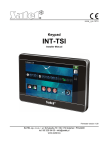
SATEL
ACU-270
3
Explanations to Fig. 1:
terminals.
RS-232 port (TTL standard) to enable updating the controller firmware. The controller can
be connected to the computer using the USB-RS converter offered by SATEL.
tamper contact.
DIP-switches.
3.1
Terminals
+12V
COM
CKM
DTM
CKE
DTE
A RS485 B -
3.2
3.2.1
power input.
common ground.
keypad bus clock.
keypad bus data.
expander bus clock.
expander bus data.
terminals provided for future applications (RS-485).
DIP-switches
Controller connected to the INTEGRA / INTEGRA Plus control panel
The DIP-switches 1-5 are used for address setting. A numerical value is assigned to each
switch. In OFF position, the value is 0. Numerical values assigned to individual switches in
ON position are shown in Table 1. The sum of numerical values assigned to switches 1-5
means the address set on the device. The address must be different from that on the other
devices connected to the expander bus of the control panel.
DIP-switch number
Numerical value
1
1
Table 1.
2
2
3
4
4
8
5
16
When connecting the controller to the control panel to which the ABAX system
controller is already connected, it is recommended that a higher address be set in the
new controller than that in the controller already connected to the control panel.
3.2.2
Controller connected to the VERSA / VERSA Plus control panel
Set the switch 8 in ON position. The status of the other switches is irrelevant.
3.3
LED
The LED indicates the status of communication with the control panel:
ON – no communication with the control panel,
blinking – communication with the control panel OK.
4. Installation of the controller
Disconnect power before making any electrical connections.