1
Sierra M6-2
SAS/SATA Protocol Analyzer
User Manual
For Software Version 5.30
Document Version 5.30
September 2013
Teledyne LeCroy Protocol Solutions Group
Trademarks and Servicemarks:
Teledyne LeCroy, Teledyne LeCroy Protocol Solutions Group, CATC, SASSuite, SATASuite, SASTracer, SATracer, SASTrainer, SATrainer, SASTracker and Avalanche are trademarks of Teledyne LeCroy. Microsoft, Windows, Windows 2000,Windows XP, Windows Vista and Windows 7 are registered trademarks of Microsoft Inc. Intel and Pentium are registered trademarks of Intel Corporation.
All other trademarks and registered trademarks are property of their respective owners.
THE SPECIFICATIONS AND INFORMATION REGARDING THE PRODUCTS IN THIS MANUAL ARE SUBJECT TO CHANGE WITHOUT NOTICE. ALL INFORMATION, EXAMPLES AND RECOMMENDATIONS IN THIS MANUAL ARE BELIEVED TO BE ACCURATE BUT ARE REPRESENTED WITHOUT WARRANTY OF ANY KIND, EXPRESS OR IMPLIED. USERS ARE FULLY RESPONSIBLE FOR THEIR APPLICATION OF ANY PRODUCTS.
THE SOFTWARE LICENSE AND LIMITED WARRANTY FOR THE ACCOMPANYING PRODUCT ARE SET FORTH IN INFORMATION THAT SHIPPED WITH THE PRODUCT AND ARE INCORPORATED HEREIN BY THIS REFERENCE. IF YOU ARE UNABLE TO LOCATE THE SOFTWARE LICENSE OR LIMITED WARRANTY, CONTACT TELEDYNE LECROY FOR A COPY.
© 2012 Teledyne LeCroy, Inc. All rights reserved.
This document may be printed and reproduced without additional permission, but all copies should contain this copyright notice.
WEEE Program Teledyne LeCroy
3385 Scott Blvd.
Santa Clara, CA 95054
TEL: 800‐909‐7112 (USA and Canada)
TEL: 408‐653‐1260 (worldwide)
Sierra M6‐2 SAS/SATA Protocol Analyzer User Manual
ii
Contents
Chapter 1: Introduction.........................................................................................17
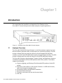
1.1 Analyzer Overview................................................................................................................ 17
1.2 Features................................................................................................................................. 18
1.3 Receiving Your Analyzer ...................................................................................................... 18
1.4 Unpacking the Analyzer ....................................................................................................... 19
1.5 Analyzer Features................................................................................................................. 19
1.6 LEDs....................................................................................................................................... 19
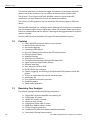
1.6.1 Status and Configuration Display ............................................................................................................ 20
1.7 Installing Your Analyzer ....................................................................................................... 20
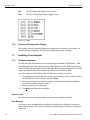
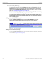
1.7.1 Software Installation .................................................................................................................................. 20
System restart ..................................................................................................................................... 20
Error Message ..................................................................................................................................... 20
1.8 Hardware Setup .................................................................................................................... 21
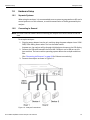
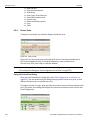
1.8.1 Separate Systems ...................................................................................................................................... 21
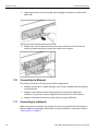
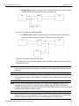
1.8.2 Connecting in General............................................................................................................................... 21
1.8.3 Cables to Use ............................................................................................................................................. 22
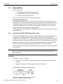
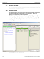
1.9 Expandability ........................................................................................................................ 23
1.9.1 Cascading with STX SYNC Expansion Cards ......................................................................................... 23
Cascading ............................................................................................................................................ 23
1.9.2 Select Device .............................................................................................................................................. 25
1.9.3 Cascading with CATC SYNC Expansion Card ........................................................................................ 30
1.9.4 Using the Power Expansion Card............................................................................................................. 30
Power Expansion Card (part number: ACC-EXP-004-X) ................................................................. 30
Power Expansion Card 2 (part number: ACC-EXP-005-X) .............................................................. 31
1.9.5 Removing Expansion Cards ..................................................................................................................... 32
1.10 Connecting via Ethernet .................................................................................................... 34
1.11 Connecting to a Network.................................................................................................... 34
1.12 Connecting over Different Subnets................................................................................... 35
1.13 TCP and UDP Ports Must Be Open to Connect over Ethernet ....................................... 35
1.14 Launching Your Analyzer................................................................................................... 35
1.15 Operating in Simulation Mode........................................................................................... 35
Sierra M6‐2 SAS/SATA Protocol Analyzer User Manual
1
Teledyne LeCroy
Contents
1.16 Using the Software ............................................................................................................. 35
1.17 Getting Started with the Protocol Analyzer...................................................................... 36
1.18 Protocol Analyzer Initiator Emulator or Host Emulator .................................................. 36
1.19 Performance Analyzer........................................................................................................ 37
1.20 Target Emulator or Device Emulator................................................................................. 37
1.21 Teledyne LeCroy SAS and SATA Protocol Suite Menu Options and Toolbars ............. 37
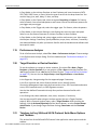
1.21.1 File ............................................................................................................................................................. 38
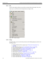
1.21.2 Setup ......................................................................................................................................................... 38
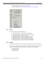
1.21.3 Session ..................................................................................................................................................... 39
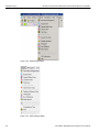
1.21.4 Analysis .................................................................................................................................................... 39
1.21.5 Viewing Captured Data ............................................................................................................................ 41
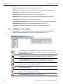
1.21.6 Navigation................................................................................................................................................. 41
1.21.7 View ........................................................................................................................................................... 42
1.21.8 Window ..................................................................................................................................................... 43
1.21.9 Help ........................................................................................................................................................... 43
1.21.10 Toolbars .................................................................................................................................................. 43
1.22 Port Status........................................................................................................................... 44
1.23 InFusion............................................................................................................................... 44
1.24 Trainer.................................................................................................................................. 44
Chapter 2: Protocol Analysis ...............................................................................47
2.1 Easy Mode (Pre-Defined Setups) ........................................................................................ 47
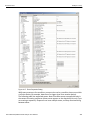
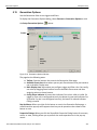
2.2 Main Window......................................................................................................................... 47
2.3 Project Tree ........................................................................................................................... 49
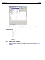
2.3.1 Capture Tab Fields..................................................................................................................................... 49
Exclude XXXX...................................................................................................................................... 49
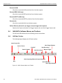
2.4 SAS/SATA Software Menus and Toolbars .......................................................................... 50
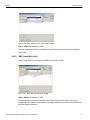
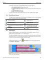
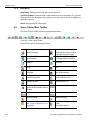
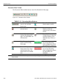
2.4.1 SAS Main Toolbar ...................................................................................................................................... 50
2.4.2 SATA Main Toolbar .................................................................................................................................... 51
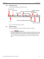
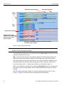
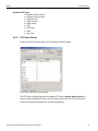
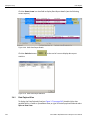
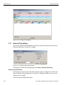
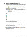
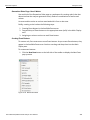
2.5 Start Recording ..................................................................................................................... 51
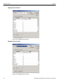
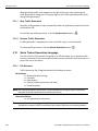
2.5.1 Launch Jammer ......................................................................................................................................... 53
2.5.2 Launch Trainer ........................................................................................................................................... 53
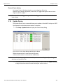
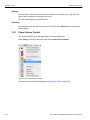
2.5.3 CrossSync Control Panel .......................................................................................................................... 53
Launching the CrossSync Control Panel ......................................................................................... 53
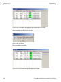
2.5.4 Save Workspace ........................................................................................................................................ 54
2.5.5 Saving a Trace Capture ............................................................................................................................. 54
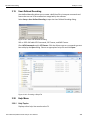
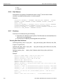
2.5.6 Exporting .................................................................................................................................................... 55
Export to Text/Excel............................................................................................................................ 56
Export to Initiator Emulator (SAS) or Host Emulator (SATA) ......................................................... 57
Export to Trainer ................................................................................................................................. 58
Export Read/Write Command Report................................................................................................ 59
2.5.7 Export Paired SAS Address Report ......................................................................................................... 59
2.5.8 Trace Properties......................................................................................................................................... 60
2
Sierra M6‐2 SAS/SATA Protocol Analyzer User Manual
Contents
Teledyne LeCroy
2.5.9 Edit Comment............................................................................................................................................. 60
2.6 Projects.................................................................................................................................. 60
New Default Project ............................................................................................................................ 60
Last Project.......................................................................................................................................... 60
2.6.1 Project File Types ...................................................................................................................................... 60
2.6.2 Example Projects ....................................................................................................................................... 61
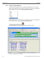
2.6.3 Run an Example Analysis Project ............................................................................................................ 61
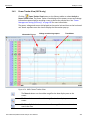
2.6.4 Patterns and Data Capture Setup ............................................................................................................. 63
2.6.5 Choose a Parameter .................................................................................................................................. 64
2.6.6 Exclude Patterns ........................................................................................................................................ 64
2.6.7 Pre and Post Trigger Data Capture .......................................................................................................... 65
2.6.8 Defining Patterns ....................................................................................................................................... 66
Primitive ............................................................................................................................................... 67
Data Pattern ......................................................................................................................................... 67
2.6.9 Protocol Errors........................................................................................................................................... 68
Protocol Error Descriptions ............................................................................................................... 68
2.6.10 STP Frame ................................................................................................................................................ 69
Available FIS Types ............................................................................................................................ 70
2.6.11 Address Frame (SAS only)..................................................................................................................... 70
2.6.12 SMP Frame (SAS only) ............................................................................................................................ 71
2.6.13 SSP Frame (SAS only) ............................................................................................................................. 72
2.6.14 FIS Type (Frame Information Structure) (SATA only)........................................................................... 72
Available FIS Types ............................................................................................................................ 73
2.6.15 STP Frame Pattern ................................................................................................................................... 73
Register Host to Device...................................................................................................................... 74
Register Device to Host...................................................................................................................... 74
Set Device Bits .................................................................................................................................... 75
DMA Activate ....................................................................................................................................... 75
DMA Setup ........................................................................................................................................... 76
BIST ...................................................................................................................................................... 76
PIO Setup ............................................................................................................................................. 77
Data ...................................................................................................................................................... 77
Vendor.................................................................................................................................................. 78
2.6.16 Trigger Setup............................................................................................................................................ 78
Snapshot Mode ................................................................................................................................... 79
Manual Trigger Mode .......................................................................................................................... 79
Any Trigger in Pattern Mode .............................................................................................................. 79
Choosing a Parameter ........................................................................................................................ 81
Triggering on a Timer ......................................................................................................................... 82
Timeout ................................................................................................................................................ 82
External/Manual Trigger ..................................................................................................................... 83
Bus Condition...................................................................................................................................... 84
Symbol ................................................................................................................................................. 84
Sierra M6‐2 SAS/SATA Protocol Analyzer User Manual
3
Teledyne LeCroy
Contents
Primitive ............................................................................................................................................... 85
ATA Command .................................................................................................................................... 87
ATAPI ................................................................................................................................................... 88
Data Pattern ......................................................................................................................................... 89
Protocol Errors.................................................................................................................................... 90
STP Frame ........................................................................................................................................... 91
Address Frame (SAS only)................................................................................................................. 92
SMP Frame (SAS only) ....................................................................................................................... 93
SSP Frame (SAS only) ........................................................................................................................ 94
SCSI Command (SAS only) ................................................................................................................ 95
FIS (Frame Information Structure) (SATA only) ............................................................................... 96
FIS Pattern (SATA only)...................................................................................................................... 97
ATA Command Pattern....................................................................................................................... 98
Soft Reset (SATA only)....................................................................................................................... 98
Sequential Trigger Mode .................................................................................................................... 99
Timer .................................................................................................................................................... 99
Defining Patterns .............................................................................................................................. 100
Triggering Order................................................................................................................................ 100
Pre-Trigger......................................................................................................................................... 101
2.6.17 Project Settings...................................................................................................................................... 101
2.6.18 Memory Settings .................................................................................................................................... 102
Trigger Position................................................................................................................................. 102
Trace File Name................................................................................................................................. 103
Auto Run ............................................................................................................................................ 103
Memory Size ...................................................................................................................................... 103
Partial Memory .................................................................................................................................. 103
Segmented Memory .......................................................................................................................... 103
Upload Manager ................................................................................................................................ 103
2.6.19 Analyzer Settings ................................................................................................................................... 104
Primitive Response Timeout............................................................................................................ 104
Disable Descrambling....................................................................................................................... 104
Show XXXX value.............................................................................................................................. 105
ALIGN Transmission Period (differs for SAS and SATA).............................................................. 105
Power Management Setting (SATA only)........................................................................................ 105
Protocol Error Mask.......................................................................................................................... 105
External Trig Out Setting.................................................................................................................. 106
External Trig In Setting..................................................................................................................... 106
Choose Port Speed ........................................................................................................................... 106
Ports Configuration .......................................................................................................................... 106
Port Configuration and Projects...................................................................................................... 108
MUX Setting (SAS only).................................................................................................................... 109
2.6.20 Add a Project Note ................................................................................................................................. 110
4
Sierra M6‐2 SAS/SATA Protocol Analyzer User Manual
Contents
Teledyne LeCroy
2.7 Advanced Mode (User-Defined) ........................................................................................ 111
2.7.1 Working in Advanced Mode .................................................................................................................... 111
State Number for Complex Trigger Sequences ............................................................................. 113
Setting Trigger Conditions............................................................................................................... 113
2.7.2 Multi-Link Triggering ............................................................................................................................... 115
2.7.3 Set Timers................................................................................................................................................. 115
2.7.4 Timeout ..................................................................................................................................................... 115
Useful Key Sequences...................................................................................................................... 118
2.8 Project Settings .................................................................................................................. 119
2.8.1 Notes ......................................................................................................................................................... 119
2.9 Emulation ............................................................................................................................ 119
2.9.1 Programming the Initiator or Host Emulator ......................................................................................... 119
Add Program Lines ........................................................................................................................... 120
2.9.2 Adding Initiator or Host Emulator Commands...................................................................................... 120
Adding an ATA Command................................................................................................................ 120
Adding a User-Defined ATA Command .......................................................................................... 122
Adding a SCSI Command (SAS only).............................................................................................. 122
Adding a User-Defined SCSI Command (SAS only) ...................................................................... 123
Adding a TASK Command (SAS only) ............................................................................................ 124
Adding an SMP Command (SAS only) ............................................................................................ 125
Adding a Frame ................................................................................................................................. 126
Adding an Event................................................................................................................................ 127
Power On ........................................................................................................................................... 128
PHY Setting Dialog............................................................................................................................ 129
Inserting Instructions ....................................................................................................................... 129
Phy Reset Sequence and Identification .......................................................................................... 133
Sample Host Emulator Program (SATA only) ................................................................................ 133
Sample Initiator Emulator Program (SAS only).............................................................................. 134
Data Blocks........................................................................................................................................ 134
Exercising Specific Addresses........................................................................................................ 134
2.9.3 Record and Play ....................................................................................................................................... 136
2.9.4 Error and Command Settings ................................................................................................................. 139
ATA Error and Command Settings.................................................................................................. 139
Outgoing ATA Frame Settings......................................................................................................... 142
Incoming ATA Frame Settings......................................................................................................... 144
SCSI Error and Command Settings (SAS only).............................................................................. 145
Outgoing SCSI Frame Settings........................................................................................................ 147
Incoming SCSI Frame Settings........................................................................................................ 149
FIS Options (SATA only) .................................................................................................................. 149
2.9.5 Initiator Setting Tab (SAS only) .............................................................................................................. 150
2.9.6 Host Setting Tab (SATA) ......................................................................................................................... 156
2.9.7 Project Settings........................................................................................................................................ 161
Sierra M6‐2 SAS/SATA Protocol Analyzer User Manual
5
Teledyne LeCroy
Contents
2.9.8 Creating a Data Block .............................................................................................................................. 161
Naming a Data Block ........................................................................................................................ 163
Editing a Data Block ......................................................................................................................... 163
Creating and Editing Data Blocks as Text ...................................................................................... 166
2.10 Performance Analysis ...................................................................................................... 167
2.10.1 Performance Analysis with Analyzer Only .......................................................................................... 167
New Performance Analysis Project................................................................................................. 167
Last Saved Performance Analysis Project ..................................................................................... 167
2.10.2 Performance Analysis Project .............................................................................................................. 167
Define Performance .......................................................................................................................... 169
Settings .............................................................................................................................................. 169
2.11 Run Hardware.................................................................................................................... 172
2.12 Target and Device Emulation........................................................................................... 172
2.12.1 Pages Tab ............................................................................................................................................... 172
Words with Settable Bits .................................................................................................................. 174
Writable Buffer Size Field................................................................................................................. 175
Error Injection Tab ............................................................................................................................ 175
2.12.2 Setting General Errors........................................................................................................................... 176
Generate Periodic Error.................................................................................................................... 177
Outgoing FIS Command Error or Outgoing FRAME Command Error ......................................... 177
Identify Errors (SAS only) ................................................................................................................ 180
2.12.3 Connection Management (SAS only) ................................................................................................... 180
Open Connection Definition............................................................................................................. 181
Close Connection Definition ............................................................................................................ 182
2.12.4 SAS Commands Errors (SAS only) ...................................................................................................... 182
Outgoing Frame Settings ................................................................................................................. 184
2.12.5 ATA Commands Errors (SATA only).................................................................................................... 187
2.12.6 Outgoing Frame Settings ...................................................................................................................... 188
2.12.7 Incoming Frame Settings ...................................................................................................................... 189
2.12.8 SATA Signature (SATA only) ................................................................................................................ 190
2.12.9 SATA Signature Errors .......................................................................................................................... 191
2.12.10 User-Defined Commands Tab............................................................................................................. 192
2.12.11 Target Emulator Settings (SAS).......................................................................................................... 193
2.12.12 Notes Tab.............................................................................................................................................. 197
2.12.13 Run Target Emulation.......................................................................................................................... 197
2.12.14 Device Emulator Settings (SATA only) .............................................................................................. 197
2.12.15 Project Note .......................................................................................................................................... 204
2.12.16 Using the Power Expansion Card ...................................................................................................... 204
2.12.17 Run Device Emulation ......................................................................................................................... 204
Chapter 3: Display Manipulation .......................................................................205
3.1 Viewer Display .................................................................................................................... 205
3.1.1 Quick View ................................................................................................................................................ 206
6
Sierra M6‐2 SAS/SATA Protocol Analyzer User Manual
Contents
Teledyne LeCroy
3.1.2 Using the Viewer Display ........................................................................................................................ 207
3.2 Trace Properties.................................................................................................................. 207
3.3 Analysis ............................................................................................................................... 208
3.3.1 Show Analysis Toolbar ........................................................................................................................... 208
3.3.2 Decoding Assignments ........................................................................................................................... 210
3.3.3 Packet View .............................................................................................................................................. 210
Packet View Metrics.......................................................................................................................... 211
Copying Packets from a Trace to a Host Emulator Script ............................................................ 212
Device Sleep (DevSlp) ...................................................................................................................... 213
3.3.4 Changing the Default View...................................................................................................................... 213
3.3.5 Spreadsheet View .................................................................................................................................... 214
Save As Text/Excel ........................................................................................................................... 215
Change Format of Logical Block Address (LBA)........................................................................... 215
3.3.6 Column View ............................................................................................................................................ 215
3.3.7 Text View .................................................................................................................................................. 216
3.3.8 Frame Inspector View .............................................................................................................................. 217
3.3.9 Waveform Display .................................................................................................................................... 218
3.3.10 Statistical Report ................................................................................................................................... 219
Generating Statistical Read/Write Report....................................................................................... 220
Report between Cursors .................................................................................................................. 221
Report between Events .................................................................................................................... 222
Statistical Report Content ................................................................................................................ 222
Report Options .................................................................................................................................. 223
General Report .................................................................................................................................. 223
Primitive Report ................................................................................................................................ 223
Bus Condition Report ....................................................................................................................... 224
ATA Command Report...................................................................................................................... 224
Time out of ATA Command Report ................................................................................................. 225
ATAPI Report..................................................................................................................................... 225
Protocol Error Report ....................................................................................................................... 226
Others Report .................................................................................................................................... 226
SSP Transport Report (SAS)............................................................................................................ 226
SMP Transport Report (SAS) ........................................................................................................... 227
SCSI Command Report (SAS).......................................................................................................... 228
SMP Command Report (SAS) .......................................................................................................... 228
Task Command Report (SAS) .......................................................................................................... 228
SAS Address Report (SAS) .............................................................................................................. 229
Lanes Report (SAS) .......................................................................................................................... 229
Read/Write Command Report (SAS) ............................................................................................... 230
Performance Report (SAS)............................................................................................................... 230
Performance Report (SATA) ............................................................................................................ 231
FIS Report (SATA)............................................................................................................................. 232
Queue Command Report (SATA)..................................................................................................... 232
Sierra M6‐2 SAS/SATA Protocol Analyzer User Manual
7
Teledyne LeCroy
Contents
PM Statistic Report (SATA) .............................................................................................................. 233
PM Performance Report (SATA) ...................................................................................................... 233
Read Write Command Report (SATA) ............................................................................................. 234
3.3.11 Statistical Report Toolbar ..................................................................................................................... 234
Export as Microsoft® Excel file ....................................................................................................... 235
Save as Text file ................................................................................................................................ 235
Print Statistical Report ..................................................................................................................... 235
Print Preview ..................................................................................................................................... 235
Report Display Settings.................................................................................................................... 236
Link With Sample View ..................................................................................................................... 237
3.3.12 Formatting the Statistical Report View ................................................................................................ 237
Filtering Column Content ................................................................................................................. 237
Sorting Column Content................................................................................................................... 239
Hiding Columns................................................................................................................................. 239
3.3.13 Histogram View ...................................................................................................................................... 240
Hide Frames....................................................................................................................................... 240
Hide Error Frames............................................................................................................................. 240
Pending IO Graph.............................................................................................................................. 241
User Defined ...................................................................................................................................... 241
Primitives ........................................................................................................................................... 241
Zoom .................................................................................................................................................. 242
3.3.14 Bus Utilization View ............................................................................................................................... 242
3.3.15 Bus Utilization Buttons ......................................................................................................................... 243
3.4 Data Report ......................................................................................................................... 243
3.4.1 Data Payload View ................................................................................................................................... 244
3.4.2 Compare Two Data Payloads.................................................................................................................. 246
3.4.3 Power Tracker View (SATA only) ........................................................................................................... 247
3.4.4 SAS Verification (SAS) ............................................................................................................................ 248
3.4.5 Compliance Test (SATA) ......................................................................................................................... 250
3.4.6 Running Verification Script Engine (VSE) ............................................................................................. 252
3.5 Navigation + View Toolbar ................................................................................................. 256
3.5.1 Go To Menu .............................................................................................................................................. 257
Locate Cursors.................................................................................................................................. 257
Go to Time Stamp ............................................................................................................................. 258
Bookmarks......................................................................................................................................... 258
Editing a Bookmark .......................................................................................................................... 259
Finding a Bookmark.......................................................................................................................... 259
Bookmark Description...................................................................................................................... 260
Set Time Stamp Origin...................................................................................................................... 261
3.5.2 Filtering ..................................................................................................................................................... 261
3.5.3 Filter Setup ............................................................................................................................................... 261
Filter Type .......................................................................................................................................... 263
Filtering Direction ............................................................................................................................. 263
8
Sierra M6‐2 SAS/SATA Protocol Analyzer User Manual
Contents
Teledyne LeCroy
Filter Idle ............................................................................................................................................ 263
Save Filter Setup ............................................................................................................................... 263
Filter Logic......................................................................................................................................... 263
Multilevel Filtering in SAS ................................................................................................................ 263
Filter descending packets from trace highlight bar....................................................................... 265
3.5.4 Selectable Filter Options for SAS........................................................................................................... 265
Command Data Pattern .................................................................................................................... 266
Bus Condition.................................................................................................................................... 266
Incomplete Frames ........................................................................................................................... 266
ATA Command .................................................................................................................................. 266
Protocol Error.................................................................................................................................... 266
ATAPI SCSI Command ..................................................................................................................... 266
Filter Check Condition...................................................................................................................... 266
Filter by Tag Number ........................................................................................................................ 267
Use Pair SAS Addresses .................................................................................................................. 269
Training Sequence ............................................................................................................................ 269
3.5.5 Selectable Filter Options for SATA ........................................................................................................ 269
Bus Condition.................................................................................................................................... 270
3.5.6 Enable Filter ............................................................................................................................................. 270
3.5.7 Filter Idle ................................................................................................................................................... 270
3.5.8 Search ....................................................................................................................................................... 271
Save Search Setup............................................................................................................................ 272
Search By........................................................................................................................................... 272
Search Direction................................................................................................................................ 272
Search From ...................................................................................................................................... 272
Search Logic...................................................................................................................................... 273
Search For ......................................................................................................................................... 273
Search Domain .................................................................................................................................. 273
Search Sub Items .............................................................................................................................. 274
3.5.9 Show/Hide Ports ...................................................................................................................................... 275
Single Port ......................................................................................................................................... 275
Multiple Ports .................................................................................................................................... 275
3.6 Packet View Toolbar ........................................................................................................... 276
3.6.1 CATC Navigation View ............................................................................................................................ 277
3.6.2 Spec View ................................................................................................................................................. 278
3.6.3 Decode Icons............................................................................................................................................ 279
3.6.4 Customize Display ................................................................................................................................... 280
Rename Port ...................................................................................................................................... 280
Show/Hide Field ................................................................................................................................ 280
Related Frames ................................................................................................................................. 281
Byte Order.......................................................................................................................................... 282
Choose Data Format ......................................................................................................................... 282
Show All Data .................................................................................................................................... 283
Sierra M6‐2 SAS/SATA Protocol Analyzer User Manual
9
Teledyne LeCroy
Contents
3.7 Port Status........................................................................................................................... 284
3.8 Toolbars............................................................................................................................... 286
3.8.1 Enabling Tool Bars .................................................................................................................................. 286
3.8.2 Cursor Position Status Bar ..................................................................................................................... 286
3.9 Status Bar ............................................................................................................................ 287
3.9.1 Search Status ........................................................................................................................................... 287
3.10 Using the Cursors and Bookmarks................................................................................. 287
3.10.1 Cursors ................................................................................................................................................... 287
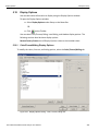
3.11 Display Configuration....................................................................................................... 288
3.11.1 Trace Viewer Configuration .................................................................................................................. 288
3.12 Set Port Alias .................................................................................................................... 292
3.13 SAS Address Alias (SAS only) ........................................................................................ 293
3.14 TxRx Vout & Preemphasis ............................................................................................... 294
3.15 Preferences ....................................................................................................................... 296
3.15.1 General Tab ............................................................................................................................................ 296
Paths .................................................................................................................................................. 296
Template Files ................................................................................................................................... 296
Other................................................................................................................................................... 297
Found Device List Mode................................................................................................................... 297
Browse Default Path ......................................................................................................................... 297
3.15.2 Trace Viewer Tab ................................................................................................................................... 298
Open Trace file In .............................................................................................................................. 298
Optimization ...................................................................................................................................... 298
Other................................................................................................................................................... 299
3.15.3 Spread Sheet View Tab ......................................................................................................................... 301
Color Setting...................................................................................................................................... 302
Anchor the Selection bar.................................................................................................................. 302
Other................................................................................................................................................... 302
3.15.4 Column View Tab ................................................................................................................................... 303
Other................................................................................................................................................... 303
3.15.5 Sampling Memory Usage Optimization................................................................................................ 303
If the Sampling Memory Usage Optimization Option is Checked ................................................ 304
If the Sampling Memory Usage Optimization Option is Not Checked ......................................... 305
3.16 Floating License ............................................................................................................... 305
3.17 External Trig Setting......................................................................................................... 306
External Trig Out Setting.................................................................................................................. 306
External Trig In Setting..................................................................................................................... 307
3.18 Update Device ................................................................................................................... 307
3.19 User-Defined Decoding .................................................................................................... 309
3.20 Help Menu.......................................................................................................................... 309
3.20.1 Help Topics............................................................................................................................................. 309
3.20.2 VSE Help Topics .................................................................................................................................... 310
3.20.3 Update License ...................................................................................................................................... 310
3.20.4 Display License Information ................................................................................................................. 310
10
Sierra M6‐2 SAS/SATA Protocol Analyzer User Manual
Contents
Teledyne LeCroy
3.20.5 Check for Updates ................................................................................................................................. 312
3.20.6 About....................................................................................................................................................... 312
3.21 Setup Menu ....................................................................................................................... 312
3.21.1 Self Test .................................................................................................................................................. 312
3.21.2 Clock Check ........................................................................................................................................... 313
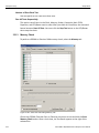
3.21.3 Memory Check ....................................................................................................................................... 314
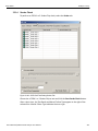
3.21.4 Serdes Check ......................................................................................................................................... 315
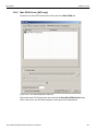
3.21.5 Crosspoint Check .................................................................................................................................. 316
3.21.6 Main FPGA Check (SATA only)............................................................................................................. 317
3.21.7 Expansion Check ................................................................................................................................... 318
3.21.8 LED/Buzzer Check ................................................................................................................................. 319
3.22 Find DUT............................................................................................................................ 320
Aliasing .............................................................................................................................................. 322
Exporting ........................................................................................................................................... 322
3.23 Power Source Control ...................................................................................................... 322
3.24 Compliance Test (SATA)................................................................................................... 323
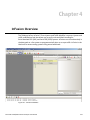
Chapter 4: InFusion Overview ...........................................................................327
4.1 Key Features ....................................................................................................................... 328
4.2 Interface............................................................................................................................... 329
4.2.1 Buttons ..................................................................................................................................................... 329
4.2.2 Menus........................................................................................................................................................ 330
File ...................................................................................................................................................... 330
Setup .................................................................................................................................................. 330
View .................................................................................................................................................... 330
Configuration..................................................................................................................................... 330
Tools................................................................................................................................................... 330
Help .................................................................................................................................................... 331
4.2.3 Main Library.............................................................................................................................................. 331
4.2.4 File Library................................................................................................................................................ 331
4.2.5 Device Ports ............................................................................................................................................. 332
Using the Device Ports Dialog ......................................................................................................... 332
4.3 Port Configuration for InFusion ........................................................................................ 333
4.4 InFusion Scenarios............................................................................................................. 336
4.4.1 Scenarios Overview ................................................................................................................................. 336
InFusion Scenario Parameters ........................................................................................................ 337
4.4.2 Global Rules ............................................................................................................................................. 338
Sequences ......................................................................................................................................... 339
4.5 Scenario Libraries .............................................................................................................. 340
4.5.1 Main Library.............................................................................................................................................. 340
4.5.2 File Libraries............................................................................................................................................. 340
4.5.3 Device Libraries ....................................................................................................................................... 341
4.6 Scenario Properties............................................................................................................ 341
Sierra M6‐2 SAS/SATA Protocol Analyzer User Manual
11
Teledyne LeCroy
Contents
SATA Smart Hold Option.................................................................................................................. 343
4.7 Scenario Events.................................................................................................................. 344
DWORD Matcher ............................................................................................................................... 347
SAS Data Pattern............................................................................................................................... 347
SATA Data Pattern ............................................................................................................................ 347
4.8 Scenario Actions ................................................................................................................ 348
Using Counters in Events and Actions........................................................................................... 350
Capturing a Data DWORD ................................................................................................................ 351
Using Captured Data DWORDs........................................................................................................ 351
4.8.1 Summary of Scenario Creation .............................................................................................................. 353
4.9 Creating Global Rules ........................................................................................................ 353
4.9.1 Example 1: Creating a Single Event and Action that Removes a Primitive........................................ 354
4.9.2 Example 2: Wait for a Primitive and Replace It with an Error .............................................................. 356
4.9.3 Example 3: Creating OR Conditions ...................................................................................................... 357
4.9.4 Example 4: Multiple Triggers and Actions............................................................................................. 359
4.9.5 Example 5: Multiple Actions on a Single Event .................................................................................... 361
4.9.6 Example 6: Using Timers ........................................................................................................................ 362
4.10 Creating a Sequence ........................................................................................................ 364
4.10.1 Example 7: Creating Two Sequences and Global Rules .................................................................... 365
4.11 Example 8: Creating a Sequence With Many States #1................................................. 370
4.12 Example 9: Creating a Sequence With Many States #2................................................. 373
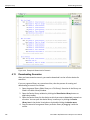
4.13 Downloading Scenarios ................................................................................................... 376
4.14 Running Scenarios ........................................................................................................... 377
4.15 Scenario Batch Files ........................................................................................................ 377
4.15.1 Script Workspace................................................................................................................................... 377
4.15.2 Error Checking ....................................................................................................................................... 380
4.15.3 Log .......................................................................................................................................................... 380
4.15.4 Statements.............................................................................................................................................. 380
IfIsStopped......................................................................................................................................... 380
Goto Label ......................................................................................................................................... 381
Run ..................................................................................................................................................... 382
Stop .................................................................................................................................................... 383
WaitForStop....................................................................................................................................... 384
Sleep................................................................................................................................................... 385
Beep ................................................................................................................................................... 385
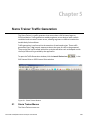
Chapter 5: Sierra Trainer Traffic Generation ....................................................387
5.1 Sierra Trainer Menus .......................................................................................................... 387
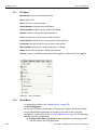
5.1.1 File Menu .................................................................................................................................................. 388
5.1.2 Setup Menu............................................................................................................................................... 388
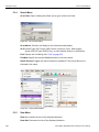
5.1.3 Generate Menu ......................................................................................................................................... 389
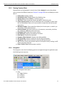
5.1.4 Search Menu............................................................................................................................................. 390
5.1.5 View Menu ................................................................................................................................................ 390
12
Sierra M6‐2 SAS/SATA Protocol Analyzer User Manual
Contents
Teledyne LeCroy
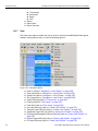
5.1.6 Tools Menu ............................................................................................................................................... 391
5.1.7 Window Menu ........................................................................................................................................... 391
5.1.8 Help Menu ................................................................................................................................................. 392
5.2 Sierra Trainer Main Toolbar ............................................................................................... 392
5.3 Setting Up for Generating Initiator Traffic ........................................................................ 393
5.4 Setting Up for Generating Target Traffic .......................................................................... 393
5.5 Creating a Traffic Generation File ..................................................................................... 393
5.5.1 Creating a New Generator File................................................................................................................ 393
5.5.2 Editing an Example Generation File....................................................................................................... 394
5.5.3 Converting an SATrainer Traffic Generation File.................................................................................. 395
5.6 Opening a Traffic Generation File ..................................................................................... 396
5.6.1 Layout ....................................................................................................................................................... 397
5.7 Overview of Generation and Global Settings Files ......................................................... 397
5.7.1 Traffic Generation (*.ssg) Files ............................................................................................................... 397
5.7.2 Settings.inc File ....................................................................................................................................... 398
5.7.3 The Global Setting “AutoAlign”.............................................................................................................. 399
5.7.4 Placing Global Settings in the Generation Block.................................................................................. 399
5.8 Primitive and Frame Definitions........................................................................................ 401
5.8.1 Special Conditions for Frames ............................................................................................................... 401
5.8.2 Primitives Decl.inc File ............................................................................................................................ 402
5.8.3 Address FramesDecl.inc File .................................................................................................................. 402
5.8.4 SSPFrames.inc File.................................................................................................................................. 402
5.8.5 SMPFrames.inc File ................................................................................................................................. 402
5.8.6 STPFrames.inc File .................................................................................................................................. 402
5.9 Starting the Script Editor ................................................................................................... 402
5.9.1 Script Editor Toolbar ............................................................................................................................... 403
5.9.2 View Options Menu .................................................................................................................................. 404
5.9.3 Pop-up Menu ............................................................................................................................................ 405
5.9.4 File Tabs ................................................................................................................................................... 405
5.9.5 Error Log................................................................................................................................................... 405
5.9.6 Tooltips ..................................................................................................................................................... 405
5.10 Multi-Port Trainer Script Assignments to Links ............................................................ 406
5.11 Generating Traffic ............................................................................................................. 407
5.11.1 Stop Traffic Generation ......................................................................................................................... 408
5.11.2 Resume Traffic Generation ................................................................................................................... 408
5.12 Sierra Trainer Generation Language............................................................................... 408
5.12.1 File Structure .......................................................................................................................................... 408
5.12.2 Language ................................................................................................................................................ 409
Comments.......................................................................................................................................... 409
Includes.............................................................................................................................................. 409
5.12.3 Settings ................................................................................................................................................... 409
5.12.4 Constants ............................................................................................................................................... 409
5.12.5 Predefined Constants ............................................................................................................................ 409
5.12.6 Data Patterns .......................................................................................................................................... 410
5.12.7 Primitives ................................................................................................................................................ 410
Sierra M6‐2 SAS/SATA Protocol Analyzer User Manual
13
Teledyne LeCroy
Contents
5.12.8 Packets/ Frames..................................................................................................................................... 412
5.12.9 Generation Block ................................................................................................................................... 414
5.12.10 Definitions ............................................................................................................................................ 414
Field Variable Declarations .............................................................................................................. 414
Changing Frame Fields .................................................................................................................... 414
Preprocessor Integer Arithmetic ..................................................................................................... 415
5.13 Trainer Script Enhancements .......................................................................................... 416
5.13.1 Variable Definition ................................................................................................................................. 417
5.13.2 Assigning Variable Values .................................................................................................................... 417
5.13.3 Expression on Variables ....................................................................................................................... 418
5.13.4 If/While in Logical Expressions ............................................................................................................ 418
5.13.5 Using Variable Values in Creating Patterns on Bus ........................................................................... 420
5.13.6 Timer ....................................................................................................................................................... 421
5.13.7 PATTERN Counter ................................................................................................................................. 421
5.13.8 Procedure Definition.............................................................................................................................. 422
5.14 Sierra Trainer Generation Commands ............................................................................ 422
5.14.1 General Commands ............................................................................................................................... 422
5.14.2 SATA Commands................................................................................................................................... 424
5.14.3 Primitive Commands ............................................................................................................................. 425
5.14.4 Primitive Category ................................................................................................................................. 427
5.14.5 Wait Commands ..................................................................................................................................... 428
5.14.6 Wait Command Groups ........................................................................................................................ 435
5.14.7 Predefined Constants ............................................................................................................................ 438
5.14.8 Generation Settings ............................................................................................................................... 439
5.15 Generation Options .......................................................................................................... 447
Generation Rules Toolbar ................................................................................................................ 448
Generation Rules Page: How It Works............................................................................................ 449
Creating Event Buttons .................................................................................................................... 449
Dragging a Button to the Main Display Area .................................................................................. 450
Assigning an Action ......................................................................................................................... 451
5.15.1 Generation Rules Pop-Up Menus ......................................................................................................... 451
5.15.2 Cell Pop-up Menu................................................................................................................................... 452
5.15.3 Action Pop-up Menu .............................................................................................................................. 452
5.15.4 Event Pop-up Menu ............................................................................................................................... 452
5.15.5 Events and Event Properties ................................................................................................................ 453
Data Pattern Mask and Match .......................................................................................................... 453
5.16 Setting Complex “Wait For” Conditions......................................................................... 454
5.16.1 Setting Conditions with the Generation Options Dialog .................................................................... 454
5.17 Find .................................................................................................................................... 455
5.17.1 Data Pattern Mask and Match ............................................................................................................... 458
5.17.2 Find Next................................................................................................................................................. 458
5.17.3 Search Direction .................................................................................................................................... 458
5.18 Display Options ................................................................................................................ 459
5.18.1 Color/Format/Hiding Display Options .................................................................................................. 459
14
Sierra M6‐2 SAS/SATA Protocol Analyzer User Manual
Contents
Teledyne LeCroy
5.18.2 Color Display Options ........................................................................................................................... 460
5.18.3 Formats Display Options ...................................................................................................................... 461
5.18.4 Hiding Display Options ......................................................................................................................... 462
5.18.5 Level Hiding Options ............................................................................................................................. 462
5.18.6 Headers Options .................................................................................................................................... 463
5.18.7 Saving Display Options ......................................................................................................................... 464
5.19 Connection Parameters ................................................................................................... 464
5.20 Resetting the Toolbar ....................................................................................................... 465
Appendix A: Creating a Pattern Generator File................................................467
6.1 Key words............................................................................................................................ 467
6.2 Comment format ................................................................................................................. 467
6.3 Primitive definition format ................................................................................................. 467
6.4 Loop definition format........................................................................................................ 467
6.5 Scramble definition format ................................................................................................ 467
6.6 Role definition format......................................................................................................... 467
6.7 END_OF_FILE definition .................................................................................................... 467
6.8 Example Pattern Generator File ........................................................................................ 468
Appendix B: China Restriction of Hazardous Substances Table ...................469
7.1 WAN Operation ................................................................................................................... 470
Appendix C: How to Contact Teledyne LeCroy................................................471
Index:.................................................................................................................. 473
Sierra M6‐2 SAS/SATA Protocol Analyzer User Manual
15
Teledyne LeCroy
16
Contents
Sierra M6‐2 SAS/SATA Protocol Analyzer User Manual
Chapter 1
Introduction
This manual describes installation and operation of the Teledyne LeCroy
Sierra M6‐2™ Protocol Analyzer and includes examples of typical applications.
Figure 1.1: Teledyne LeCroy Sierra M6-2 Protocol Analyzer
1.1
Analyzer Overview
The Sierra M6‐2 SAS/SATA Protocol Analyzer is a serial bus analyzer, supports host and device emulation, generates traffic, and provides error injection functionality. The SAS analyzer software performs serial bus analysis for Serial Attached SCSI (SAS) data transfers, as well as Serial ATA (SATA) data transfers through STP data transfers. The SATA analyzer software performs serial bus analysis for Serial ATA (SATA) data transfers.
The Sierra M6‐2 Analyzer helps Hardware, Firmware, Design, and Application Engineers troubleshoot and diagnose SAS and SATA problems within their product. The analyzer supports the following:
Capture, triggering, and filtering of Serial Attached SCSI packets or Serial ATA packets
Generation of bus traffic as a SAS Initiator Emulator or a SATA Host Emulator, while monitoring and analyzing results
SAS target emulation and SATA device emulation
Running a Pattern Generator
TX Vout on transmitters for test and characterization CATC API
Sierra M6‐2 SAS/SATA Protocol Analyzer User Manual
17
Teledyne LeCroy
Features
The analyzer provides for bi‐directional trigger and capture of commands, primitives, patterns and all bus conditions. You can capture all frames and/or exclude traffic. The InFusion™ Error Injector and Traffic Modifier is an error injector and traffic modification tool that allows you to verify real‐world fault handling.
The Trainer is a traffic generator that can emulate a SAS initiator/target or SATA host/
device.
The Sierra M6‐2 Analyzer has a USB port and an Ethernet port to connect to a computer. You can cascade analyzer units for higher port counts. The analyzer allows you to select frames to include and exclude for capture. Capturing can be triggered based on a specific event or manually.
The Sierra M6‐2 Analyzer provides a full range of views and statistical reports.
1.2
Features
1.3
6 Gb/s SAS/SATA protocol analysis or error injection
Native PHY for fast lock time
Easy mode triggering
Cascade up to 8 analyzers
Sync with Teledyne LeCroy Sierra and STX family products
CrossSync Control Panel
Hardware filtering
Automatic error detection
Comprehensive decoding of SAS and SATA data traffic
Logical and chronological traffic displays
Statistical reporting
Trace memory of 4 GB or 8 GB
GbE & USB 2.0 host interfaces
Capture, triggering, and filtering of Serial Attached SCSI packets or Serial ATA packets
TX Vout on transmitters for test and characterization Automation API
Error Injection Functionality (Jammer) Emulation support
Trainer traffic generation
Receiving Your Analyzer
The analyzer package includes the following components:
18 1 Sierra M6‐2 Analyzer identified in the packing list
2 SATA cables, 0.5 meter
1 USB A‐B 2.0 cable, 1.8 meter
1 Ethernet cable, 10 feet
1 10‐position ribbon cable, 6 inches
1 SMB RA to SMB RA cable, 6 inches
1 Three‐Prong AC power cord
1 Installation CD ROM with software and documentation
1 Sierra M6‐2 Getting Started manual
Sierra M6‐2 SAS/SATA Protocol Analyzer User Manual
Unpacking the Analyzer
1.4
Teledyne LeCroy
Unpacking the Analyzer
Inspect the received shipping container for any damage. Unpack the container and account for each of the system components listed on the accompanying packing list. Visually inspect each component for absence of damage. In the event of damage, notify the shipper and Teledyne LeCroy Corporation. Retain all shipping materials for shipper’s inspection.
1.5
Analyzer Features
The Analyzer has the following features:
Power Switch (0/1)
Trigger, Error, Link, Speed, and Frame/OOB LEDs (see next page)
Port 1 Initiator/Host SATA connector
Port 1 Target/Device SATA connector
Port 2 Initiator/Host SATA connector
Port 2 Target/Device SATA connector
Status and Configuration LCD Display
External Trigger Input and Output
USB port for host connectivity
Gigabit Ethernet port for network connectivity
Power In (on back)
Expansion In/Out data ports and Clock In/Out connectors (on back)
Figure 1.2: Front Panel
1.6
LEDs
Each link is supported by LEDs with the following functionality:
GreenThis LED is illuminated during the OOB (Out of Bound) sequence before the link is established and after link is established it indicates traffic on the bus.
Orange
Yellow
This LED is illuminated as follows:
Speed
Initiator
Target
1.5G
Off
Off
3.0G
On
Off
6.0G
On
On
This LED is illuminated when a link is established.
Sierra M6‐2 SAS/SATA Protocol Analyzer User Manual
19
Teledyne LeCroy
Installing Your Analyzer
Red
This LED illuminates when an error occurs.
Blue
This LED is illuminated when a trigger occurs.
Figure 1.3: LEDs
1.6.1
Status and Configuration Display
The Analyzer front LCD display indicates the configuration and status of operations. For example, during initialization, the LCD panel displays boot status messages.
1.7
Installing Your Analyzer
1.7.1
Software Installation
The SAS and SATA software works on systems using the Windows® XP, Windows 7 (x86, x64) Windows 8 (x86, x64), Windows Server 2003, Windows Server 2008 and Windows Server 2012 R2 operating systems. 64‐bit Windows OS is recommended because it allows using more RAM memory. Other Operating Systems limit the RAM to 3GB.
Insert the Installation CD ROM into the CD/DVD drive on the host machine.
1. The installation automatically starts setup, unless Auto Run is off. In that case, select the CD ROM from “My Computer” and click Setup.
2. After the warning to close all other programs and before starting the installation, the Install component selection opens.
3. Select components for installation.
4. Click Next to complete the installation.
System restart
You must restart your computer before you can use your Analyzer software.
Error Message
If you get an error message during installation of the drivers for Window, consult your system administrator. Your system may allow only administrator‐level users to copy such driver files.
20 Sierra M6‐2 SAS/SATA Protocol Analyzer User Manual
Hardware Setup
Teledyne LeCroy
1.8
Hardware Setup
1.8.1
Separate Systems
When using the analyzer, it is recommended to use a system to generate bus traffic and a second system to run the software, to avoid characterization of traffic generated by the analyzer.
1.8.2
Connecting in General
Note: You must install the software before connecting the analyzer to the host machine for the first time.
To set up the analyzer:
1. Plug the power adapter into the unit, and then plug the power adapter into a 100V–
240V, 50Hz–60Hz, power outlet. Turn on the Power switch.
At power on, the analyzer will go through initialization as shown on the LCD display.
2. Connect the USB cable between the Sierra M6‐2 USB port and a USB port on the host machine. The host machine operating system detects the analyzer and driver files.
(See “Connecting via Ethernet” on page 34 for Ethernet connectivity.)
3. Connect the analyzer as shown in Figure 1.4: .
Figure 1.4: Analyzer Connections
Sierra M6‐2 SAS/SATA Protocol Analyzer User Manual
21
Teledyne LeCroy
1.8.3
Hardware Setup
Cables to Use
When using Sierra as a Host Emulator, connect from Target to hard drives using a SATA cable. When using Sierra as a Device Emulator, connect from Initiator to HBAs using a SATA cable.
Figure 1.5: Sierra M6-2 Connected as an Analyzer
22 Sierra M6‐2 SAS/SATA Protocol Analyzer User Manual
Expandability
1.9
Teledyne LeCroy
Expandability
You can expand by:
Cascading with STX SYNC Expansion Cards
Cascading with CATC SYNC Expansion Cards
Using the Power Expansion Card
You can remove expansion cards with two simple tools.
Cascading and Memory Size
For example, you have two units. The first one has 2 GB memory. The second one has 4 GB memory. The system shows the entire memory as 6 GB. If you set buffer size to 6 GB, the system programs the first board for 2 GB and the second board for 4 GB. You can consider this ratio when you set buffer size to any value. For example, if you set buffer size to 2 GB, the system programs the first board for
(2*2)/6 GB and the second board for (2*4)/6 GB. Any unit that has more memory will have larger buffer size.
1.9.1
Cascading with STX SYNC Expansion Cards
You can use cascading of analyzer units for higher port count, by daisy chaining the units through the provided Expansion and Clock In/Out interfaces on the analyzer back. Connect “Out” connectors to “In” connectors of the next unit in the chain, for both Signal and Clock interfaces. You must provide external hubs for connecting the host machine to these units using USB or Ethernet. You can cascade up to eight units. Use the STX SYNC Expansion Cards to sequentially trigger the State Machine in Advanced mode.
If you mix Sierra M6‐4, Sierra M6‐2, and STX A6‐4 analyzers/emulators, put Sierra boards first, then STX.
Note: Because chain connections for cascading boards cause delay of signals, traffic on different boards is not completely time synchronized, with about one DWORD difference between consecutive boxes.
Cascading
To set up the units in a cascade:
1. Connect all units to the host machine using either USB or Ethernet cables. You can use hubs.
2. Locate the Expansion and Clock ports on the back of each unit.
Figure 1.6: Expansion and Clock Ports
Sierra M6‐2 SAS/SATA Protocol Analyzer User Manual
23
Teledyne LeCroy
Expandability
3. Connect the OUT Clock connector of Unit 1 to the IN Clock connector of Unit 2 using the supplied stacking cables. Similarly connect any additional units.
4. Connect the OUT 10‐pin connector of Unit 1 to the IN 10‐pin connector of Unit 2 using the supplied stacking cables. Similarly connect any additional units.
Note: Unit 1 must be the unit that has the first out connection.
Note: The Self Test, SAS Verification Test, SATA Compliance Test and Update License functions only work on unit 1 when the analyzers are set up in cascading mode.
Figure 1.7: Cascading
Correct way to connect:
The black color pin of the
ribbon wire is connected
the same way between
2 connectors.
Cascading works correctly
in this case.
Black color pin
of ribbon wire
Figure 1.8: Cascading Correctly
24 Sierra M6‐2 SAS/SATA Protocol Analyzer User Manual
Expandability
Teledyne LeCroy
Incorrect way to connect:
The black color pin of the
ribbon wire is connected
in a different way between
the 2 connectors.
Cascading works incorrectly
in this case, the boxes are
connected but no traces
are captured.
Black color pin
of ribbon wire
Figure 1.9: Cascading Wrongly
5. Make a note of the last four digits of the MAC address of the unit designated as
Unit 1 and the last four digits of the other units, in order of connection.
Figure 1.10: Address Digits
IMPORTANT!
1.9.2
Power up all units before starting the software.
Select Device
After starting the software, click on Configuration and select All Connected Devices (see
the following screen capture).
Sierra M6‐2 SAS/SATA Protocol Analyzer User Manual
25
Teledyne LeCroy
Expandability
Figure 1.11: Connecting to All SAS Device(s)
Figure 1.12: Connecting to All SATA Device(s)
The Select Device dialog allows connecting and disconnecting analyzers on the fly,
without restarting the application.
26 Sierra M6‐2 SAS/SATA Protocol Analyzer User Manual
Expandability
Teledyne LeCroy
The new Device List (introduced in version 4.10) mandates using updated firmware in
order to detect the analyzer over Ethernet. Thus, the analyzer must be updated over USB
before it can be used remotely over Ethernet. This is applicable for any update from
version 4.00 or earlier to any version from 4.10 or later.
The following Select Device dialog displays. The colors in the ‘Location’ column mean the
following:
Red: Firmware and/or BusEngine components need to be updated to the latest
version
Light Blue: The device is ready to be connected.
Yellow: The device is locked.
Green: The software is connected and ready to run.
Figure 1.13: Select Device Dialog
Note: Click Refresh Device List to display all the devices on the network.
The Select Device dialog displays the following buttons:
Set Alias Name Click Set Alias Name to display the Set device alias name dialog as shown below.
Figure 1.14: Set Device Alias Name Dialog
Disconnect Click Disconnect to disconnect a device.
Sierra M6‐2 SAS/SATA Protocol Analyzer User Manual
27
Teledyne LeCroy
Expandability
Add Device... Click Add Device to add a device with a static IP address.
Figure 1.15: Add Device with Static IP Dialog
Remove Device Click Remove Device to remove a previously added device.
IP Settings... Click IP Setting to reset IP settings of a device. The following IP Setting dialog displays.
Figure 1.16: IP Setting Dialog
Networks... Click Networks to select a network adapter. The following dialog displays.
Figure 1.17: Select Adapter Dialog
28 Sierra M6‐2 SAS/SATA Protocol Analyzer User Manual
Expandability
Teledyne LeCroy
Refresh Device List Click Refresh Device List to refresh the device list.
To connect to a device, select a device which is Ready to Connect and click the Connect button on the right. The Connection Properties dialog is displayed (see the following
screen capture).
Figure 1.18: Connection Properties Dialog
Specify one of the actions from the following:
Automatically connect to the device
Ask if I want to connect to the device
Take no action
If ‘Automatically connect to the device’ is selected, the next time the application opens
the device will be automatically connected.
In the Select Device dialog chained or cascaded units are displayed in the Device column
with a [ (square bracket) icon. The sequence of the units is displayed in the Order column.
See the following screen capture.
Figure 1.19: Select Device Dialog Displaying Unit 1 and Unit 2 Chained
Sierra M6‐2 SAS/SATA Protocol Analyzer User Manual
29
Teledyne LeCroy
Expandability
Note: When using STX Sync cards, you need to manually specify the order of the chained units. To
match your unit sequence to the address for each unit in the Select Device dialog, click the
pull down tab under the Order heading (on the right side) and select unit numbers: 1 for
Unit 1, 2 for Unit 2, and so on. This determines the order in which the cascaded ports appear in
the trace. When using the CATC Sync cards the order is automatically detected.
IMPORTANT!
1.9.3
Power up all units before starting the software.
Cascading with CATC SYNC Expansion Card
You can cascade up to eight Sierra Analyzers, if they all have a CATC SYNC expansion card.
Note: If Sierra M6‐2 has a CATC SYNC Expansion Card, you can cascade with Sierra M6‐1. If Sierra M6‐2
has an STX SYNC Expansion Card, you cannot cascade with Sierra M6‐1.
1.9.4
Using the Power Expansion Card
Two types of Power Expansion Cards are available and the type must be specified when
ordering the unit.
Power Expansion Card (part number: ACC‐EXP‐004‐X)
Power Expansion Card 2 (part number: ACC‐EXP‐005‐X)
Power Expansion Card (part number: ACC‐EXP‐004‐X)
You can use the Power Expansion Card to power the drives to test for Emulation,
SATA Compliance, and SAS Verification. The Power Expansion Card can supply 5 V or 12 V.
Holes in the
Expansion Card
You can turn the card on or off through the software during SATA Compliance or
SAS Verification tests.
30 Sierra M6‐2 SAS/SATA Protocol Analyzer User Manual
Expandability
Teledyne LeCroy
You can turn the card on or off through the BusEngine by user‐emulation scripts during
Emulation.
Power Expansion Card 2 (part number: ACC‐EXP‐005‐X)
This card has several capabilities:
Supplies power to devices at 12v, 5v, 3.3v, 1.5v and/or 1.2v. This is controlled by
the application (see “Power On” on page 128).
Allows toggling the new "Device Sleep" (DevSlp) signal to put SATA devices into
sleep (see “Adding an Event” on page 127 and Figure 2.103 on page 128).
Allows monitoring in the trace of the DevSlp signal as generated by the Trainer or
Host Emulator, as well as when generated directly from a Host (using a dedicated
DevSlp cable). Also see “Device Sleep (DevSlp)” on page 213.
Allows CATC Sync functionality to enable cascading, so there is no need to toggle
between the Power Expansion Card and the Sync Expansion Card.
Allows power measurement to monitor and record the power, current and volt‐
age being used by the device it powers (will be supported in a future software
release).
It is shipped with the following three cables:
Standard 4‐pin power connector (ground, 5v, 12v only): This is a direct replace‐
ment for the existing Power Expansion Card cable.
Sierra M6‐2 SAS/SATA Protocol Analyzer User Manual
31
Teledyne LeCroy
Expandability
1.9.5
SATA 15‐pin power segment connector: This plugs in to the power segment of
the standard SATA connector, allowing to control and monitor its power and
DevSlp.
DevSlp cable: This cable is used to monitor DevSlp levels when the Device is con‐
nected directly to the Host. It is up to the user to supply a copy of the DevSlp sig‐
nal coming from the Host to connect to the DevSlp wire of this cable, as well as
to connect the adequate ground wire of this cable.
Removing Expansion Cards
You can remove both expansion cards using two tools:
Standard (flat blade) 3/16” screwdriver
Teledyne LeCroy Extraction Tool (part number 230‐0160‐00)
To remove an expansion card, follow these steps:
1. Unplug the system from AC power and turn the system so the expansion port is
facing you. Note the two retaining screws and the holes for the extraction tool that
are located on the panel of the expansion card.
Holes in the
Expansion Card
2. Insert the extraction‐tool prongs into the holes in the expansion card panel.
Note: If the prongs do not slip easily into the holes, use a small nail file or similar device to remove
paint from the prongs.
32 Sierra M6‐2 SAS/SATA Protocol Analyzer User Manual
Expandability
Teledyne LeCroy
3. Rotate the extraction tool to a horizontal position to lock the prongs into place and
make a handle.
4. Using the screwdriver, loosen both retaining screws by rotating them counter‐
clockwise approximately two full turns, until feeling slight resistance. Do not force the retaining screws after two turns.
Sierra M6‐2 SAS/SATA Protocol Analyzer User Manual
33
Teledyne LeCroy
Connecting via Ethernet
5. Using the extraction tool as a handle, gently wriggle the expansion card forward
about 1/8”.
6. Repeat steps 4 and 5 approximately three times, until the card is free from the
retaining screws and you can remove the card from the system.
1.10
Connecting via Ethernet
The Ethernet connection can have any of these configurations:
1. Analyzer connected to a network using a hub or switch, Gigabit Ethernet interface,
or similar device.
2. Analyzer connected to the host machine (machine running the application
software), using a hub or switch, Gigabit Ethernet interface, or similar device.
3. Analyzer connected directly to the host machine using a SATA cable.
1.11
Connecting to a Network
When connected to a network, the analyzer can communicate with the DHCP server to
obtain IP address configuration information in order to establish a connection. Refer to
“Select Device” on page 25.
34 Sierra M6‐2 SAS/SATA Protocol Analyzer User Manual
Connecting over Different Subnets
1.12
Teledyne LeCroy
Connecting over Different Subnets
If the host machine (with the Sierra software) and Sierra M6‐2 are on the same subnet,
they will see each other’s broadcasts, and the Sierra M6‐2 application will automatically
appear in the Select Device dialog, from which you can select a device (as described in the
previous section).
If the host machine and Sierra M6‐2 do not reside on the same subnet, they will not see
each other automatically. You must add the Sierra M6‐2 IP address manually. To add the IP
address, use the Add Device button (see Figure 1.15 on page 28).
1.13
TCP and UDP Ports Must Be Open to Connect over Ethernet
WARNING: Check your firewall settings before making Ethernet connections. Incorrect
firewall settings can prevent Teledyne LeCroy applications from detecting
analyzers on the network, though Ping works correctly. Consult your Firewall
documentation to allow Teledyne LeCroy applications access to the network.
The following TCP and UDP ports must be open to connect over the Ethernet:
1.14
TCP Port: 4000 to 4003
UDP Ports: 4015 to 4017
Launching Your Analyzer
To launch the software, double‐click the SAS or SATA Icon in the Program Manager
Window.
1.15
Operating in Simulation Mode
The SAS/SATA applications operate in Simulation Mode by default if the software detects
no hardware.
The Analyzer software launches and displays the appropriate tool bar, but with the
limitation that the Analyzer operates only on static, previously captured, bus data.
Limitations
1.16
Simulation Mode lets you try all of the available functions, but the system
is not capturing any real data and is displaying only
pre‐captured results.
Using the Software
The Sierra M6‐2 application has the Teledyne LeCroy SAS Protocol Suite and the Teledyne
LeCroy SATA Protocol Suite.
The Teledyne LeCroy SAS Protocol Suite can be a:
Protocol Analyzer: Captures data, triggers on events, and saves. Easy Mode
allows standard Trigger and Data capture. Advanced Mode allows you to pro‐
Sierra M6‐2 SAS/SATA Protocol Analyzer User Manual
35
Teledyne LeCroy
Getting Started with the Protocol Analyzer
gram custom triggering in and out, capturing, state jumps, and timers (see “Pro‐
tocol Analysis” on page 47).
Jammer: The InFusion™ Error Injector and Traffic Modifier is an error injector
and traffic modification tool that allows you to verify real‐world fault handling
(see “InFusion Overview” on page 327).
Protocol Analyzer Initiator Emulator: Generates bus traffic for capture. It also
has Easy Mode and Advanced Mode (see “Emulation” on page 119).
Target Emulator: Acts as target (see “Target and Device Emulation” on
page 172).
The Teledyne LeCroy SATA Protocol Suite can be a:
1.17
Protocol Analyzer: Captures data, triggers on events, and saves. Easy Mode
allows standard Trigger and Data capture. Advanced Mode allows you to pro‐
gram custom triggering in and out, capturing, state jumps, and timers (see “Pro‐
tocol Analysis” on page 47).
Jammer: The InFusion™ Error Injector and Traffic Modifier is an error injector
and traffic modification tool that allows you to verify real‐world fault handling
(see “InFusion Overview” on page 327).
Protocol Analyzer Host Emulator: Generates bus traffic for capture. It also has
Easy Mode and Advanced Mode (see “Emulation” on page 119).
Device Emulator: Acts as device (see “Target and Device Emulation” on
page 172).
Getting Started with the Protocol Analyzer
To use the software for protocol analysis, first select File > New > Protocol Analyzer for a
new project or File > Open an existing protocol analysis file: .sac for a SAS file or .stc for a
SATA file (see “Protocol Analysis” on page 47). You can also open a .scs SAS Sample file or
.sts SATA Sample file. Example files are in the Examples folder. You can also use Project Setup > Last Protocol Analyzer.
On the Capture tab, select to capture Everything or Pattern. For Pattern, select a Pattern.
You can exclude patterns and frames. You can use different patterns for pre‐trigger and
post‐trigger.
On the Trigger tab, select the trigger type. For Pattern, select the pattern.
On the Settings tab, select trigger position and memory use.
Change the Analyzer settings if necessary. Change the port Speed if necessary.
Use Advanced Mode only after you become familiar with the hardware and software and
have special needs.
1.18
Protocol Analyzer Initiator Emulator or Host Emulator
To use the software for protocol analysis to generate host traffic, first select File > New > Protocol Analyzer Initiator Emulation or Protocol Analyzer Host Emulation for a new
project or File > Open an existing Pattern Generator file: .spg for a single‐role file (see
“Emulation” on page 119).
36 Sierra M6‐2 SAS/SATA Protocol Analyzer User Manual
Performance Analyzer
Teledyne LeCroy
In Easy Mode, on the Initiator Emulator or Host Emulator tab, insert instances of ATA,
SCSI, TASK, SMP, Frame, or Event. Select the type of each from the drop‐down lists. You
can also loop, go to, wait, delay, if...then, and stop.
In Easy Mode, on the Capture tab, select to capture Everything or Pattern. For Pattern,
select a Pattern. You can exclude patterns and frames. You can use different patterns for
pre‐trigger and post‐trigger.
In Easy Mode, on the Trigger tab, select the trigger type. For Pattern, select the pattern.
In Easy Mode, on the Initiator Setting or Host Setting tab, select the port and speed.
Select to run the Pattern Generator or Initiator Emulator or Host Emulator.
In Easy Mode, on the Settings tab, select trigger position and memory use. Also change
the Analyzer settings if necessary. Specify addresses, stops, times, and sizes, if necessary.
Use Advanced Mode only after you become familiar with the hardware and software and
have special needs.
1.19
Performance Analyzer
To do a Performance Analysis, select File > New > Performance Analyzer. Choose settings
in the Performance Analysis dialog. Click Run Hardware (see “Performance Analysis” on
page 167.)
1.20
Target Emulator or Device Emulator
To use the software as a target or device emulator, first select File > New > Target Emulator or Device Emulator for a new project or File > Open an existing Emulator file:
.std Target Emulator file or .sde Device Emulator file (see “Target and Device Emulation”
on page 172). You can also use Project Setup > Last Target Emulator or Last Device Emulator.
In the Pages tab, change settings for the supported pages if necessary.
In the Error Injection tab, select General periodic errors, Identify frames,
Connection Management open and close connection errors, SAS Commands and events
errors, ATA Commands errors, or SATA Signature content.
Use the User‐defined Commands tab only after you have become familiar with
operations.
In the Settings tab, select addresses, sizes, times, and ports, if necessary.
You can capture traffic when using an Analyzer project (but not a Target Emulator
project). With a Protocol Analyzer open, open a Target Emulator. After checking the
settings, click the Activate/Deactivate (Active) device button. or select Project Setup > Active Device. If you change Target Emulator settings, Deactivate and then Activate Device.
1.21
Teledyne LeCroy SAS and SATA Protocol Suite Menu Options
and Toolbars
This section lists all the SAS and SATA Protocol Suite application menu options and the
toolbars.
Sierra M6‐2 SAS/SATA Protocol Analyzer User Manual
37
Teledyne LeCroy
1.21.1
Teledyne LeCroy SAS and SATA Protocol Suite Menu Options and Toolbars
File
The File menu options allows you to perform common tasks such as open, close, save,
export, print, send files and exit the application (see Figure 1.20).
Figure 1.20: File Menu Option
1.21.2
Setup
For special work, you can use the Setup menu (see the following figure) to perform the
following actions:
38 Configure TxRxVout & Pre‐emphasis (see “TxRx Vout & Preemphasis” on
page 294)
User Defined Decoding (see “User‐Defined Decoding” on page 309)
External Trig Setting (see “External Trig Setting” on page 306)
Update Device (see “Update Device” on page 307)
All Connected Devices (see “Select Device” on page 25)
Find DUT (see “Find DUT” on page 320)
Power Source Control (see “Power Source Control” on page 322)
Manage Setup Licences (see “Floating License” on page 305)
Set Preferences (see “Preferences” on page 296)
Perform a Self Test (see “Self Test” on page 312)
Create a Data Block (see “Data Blocks” on page 134)
Sierra M6‐2 SAS/SATA Protocol Analyzer User Manual
Teledyne LeCroy SAS and SATA Protocol Suite Menu Options and Toolbars
Teledyne LeCroy
Set Port Alias (see “Set Port Alias” on page 292)
Set SAS Address Alias (see “SAS Address Alias (SAS only)” on page 293)
Figure 1.21: Setup Menu Option
1.21.3
Session
The Session menu has the following options:
1.21.4
Start Capture/Record ‐ Start capture or record a trace
Pause Capture/Record ‐ Aborts the capture without saving
Stop Capture/Record ‐ Stops the hardware
Start Target Emulator ‐ Starts the target emulator (SAS)
Stop Target Emulator ‐ Stops the target emulator (SAS)
Start Device Emulator ‐ Starts the device emulator (SATA)
Stop Device Emulator ‐ Stops the device emulator (SATA)
Analysis
The Analysis menu allows you to view captured data (see the following screen capture).
Menu items and toolbar options are enabled or disabled and displayed or hidden based
on the type of window open. The following types of windows can be displayed:
No active window
Project file open
Trace file open
Sierra M6‐2 SAS/SATA Protocol Analyzer User Manual
39
Teledyne LeCroy
Teledyne LeCroy SAS and SATA Protocol Suite Menu Options and Toolbars
Figure 1.22: SAS Analysis Menu
Figure 1.23: SATA Analysis Menu
40 Sierra M6‐2 SAS/SATA Protocol Analyzer User Manual
Teledyne LeCroy SAS and SATA Protocol Suite Menu Options and Toolbars
1.21.5
Teledyne LeCroy
Viewing Captured Data
Captured data can be displayed in several views. Select Analysis from the drop‐down
menu to access the different views (see “Analysis” on page 208). You can display the same
data in:
1.21.6
Packet View: Displays packets
Spreadsheet View: Displays Packet View fields by time
Column View: Shows DWORDs in columns by port
Text View: Shows transaction frames, grouped in columns by port
Frame Inspector View: Has lots of information that is available in Packet View,
but not Spreadsheet View, so it is most useful in conjunction with the Spread‐
sheet View.
Waveform Display: Shows waveform display for all active ports, on which you
can perform timing measurements
Statistical Report: generate statistics for all transports, commands, primitives,
bus conditions, addresses, lanes, and errors
Histogram View: Shows frame‐type transfers
Bus Utilization: Displays the utilization of the bus
Data Reports: Displays data payloads
Compare 2 Data Payloads: Compares two data payloads
SAS Verification: Verifies compliance with the SAS specification
Compliance Test: Verifies compliance with the SATA specification
VSE: Perform custom post‐process analysis of the open trace by running a verifi‐
cation script over the trace
Power Tracker View: Displays power statistics
Navigation
The Navigation menu has the following options to navigate through the application (see
the following screen capture).
Figure 1.24: Navigation Menu Option
Goto
Trigger Position
X Position
Y Position
Packet No
Sierra M6‐2 SAS/SATA Protocol Analyzer User Manual
41
Teledyne LeCroy
Teledyne LeCroy SAS and SATA Protocol Suite Menu Options and Toolbars
Time Stamp
Bookmark
Begin
End
Search
Search Next
Search Previous
1.21.7
View
The View menu options allows the user to zoom in and out, enable/disable filtering and
toolbars among other actions. It has the following options.
Figure 1.25: View Menu Option
42 Zoom In (refer to “Navigation + View Toolbar” on page 256)
Zoom Out (refer to “Navigation + View Toolbar” on page 256)
Actual Size (refer to “Navigation + View Toolbar” on page 256)
Tile Views (refer to “Navigation + View Toolbar” on page 256))
Enable Filtering (refer to “Filter Setup” on page 261)
Filtering (refer to “Filter Setup” on page 261)
Filter Idles (refer to “Filter Setup” on page 261)
Link Layer‐SAS only (refer to “Packet View Toolbar” on page 276)
Transport Layer‐SAS only (refer to “Packet View Toolbar” on page 276)
Application Layer‐SAS only (refer to “Packet View Toolbar” on page 276)
Pack/Unpack Repeated Primitives‐SAS only (refer to “Packet View Toolbar” on
page 276)
Physical Layer‐SATA only (refer to “Packet View Toolbar” on page 276)
FIS Layer‐SATA only (refer to “Packet View Toolbar” on page 276)
Sierra M6‐2 SAS/SATA Protocol Analyzer User Manual
Teledyne LeCroy SAS and SATA Protocol Suite Menu Options and Toolbars
1.21.8
Teledyne LeCroy
Command Layer‐SATA only (refer to “Packet View Toolbar” on page 276)
Wrap Packets (refer to (refer to “Packet View Toolbar” on page 276)
Tool bar (allows you to customize the toolbar with the options given below)
Main
Record+Capture
Analysis
Navigation+View
Column View
Cursor position
Target Emulator
Status Bar (refer to “Cursor Position Status Bar” on page 286)
Window
The Window menu has the following options:
1.21.9
Cascade: Displays all open windows in an overlapping arrangement.
Tile Horizontal: Displays all open windows in a above‐below arrangement.
Tile Vertical: Displays all open windows in a side‐by‐side arrangement.
Arrange Icons: Arranges minimized windows at the bottom of the display.
Close All: Closes all windows.
Help
For more information see “Help Menu” on page 309.
1.21.10 Toolbars
The toolbars enable you to perform several actions, some of which are listed below.
Show or hide fields and ports, change port names, and change data format.
Show the layers and channels using their toolbars.
Decode using the Decode toolbar.
Search and Filter.
There are six sets of toolbars (see the following screen capture):
Main Toolbar ‐ For details on the Main Toolbar refer to “SAS Main Toolbar” on
page 50 and “SATA Main Toolbar” on page 51.
Record Capture Toolbar ‐ For additional information see “SAS Main Toolbar” on
page 50 and “SATA Main Toolbar” on page 51.
Target/Device Emulator Toolbar ‐ For additional information see “SAS Main Tool‐
bar” on page 50 and “SATA Main Toolbar” on page 51.
Navigation + View Toolbar ‐ For additional information see “Navigation + View
Toolbar” on page 256.
Show Analysis Toolbar ‐ For additional information see “Show Analysis Toolbar”
on page 208.
Packets View Toolbar ‐ For additional information see “Packet View Toolbar” on
page 276.
Sierra M6‐2 SAS/SATA Protocol Analyzer User Manual
43
Teledyne LeCroy
Port Status
Figure 1.26: SAS/SATA Protocol Suite Toolbars
1.22
Port Status
You can display an overview of the active ports by clicking the buttons at the bottom right
of the main window (see “Port Status” on page 284).
1.23
InFusion
The Teledyne LeCroy InFusion™ Error Injector and Traffic Modifier is an error injector and
traffic modification tool for traffic passing through the Jammer. It allows you to verify
real‐world fault handling for Serial Attached SCSI (SAS) and Serial ATA (SATA) systems.
Click on the Jammer icon
to invoke the Teledyne LeCroy SAS or SATA InFusion,
see “InFusion Overview” on page 327.
You can toggle between the InFusion and Analyzer panes by using the Alt+Tab keys, the
Windows Task Bar or by pressing the respective toolbar button in each pane.
1.24
Trainer
The SAS Trainer is a traffic generator that can emulate a SAS initiator/target or
SATA host/device. Traffic generation enables engineers to test designs under realistic
conditions and to transmit known errors, allowing engineers to observe how devices
handle faulty link conditions.
Traffic generation is performed via the execution of text‐based scripts. These traffic
generation files (*.ssg) contain statements about the types of traffic to be generated.
These script files can be edited with either a simple text editor such as Notepad or with
the included Script Editor utility.
44 Sierra M6‐2 SAS/SATA Protocol Analyzer User Manual
Trainer
Teledyne LeCroy
Click on the Trainer icon
to invoke the Teledyne LeCroy SAS or SATA Trainer, see
“Sierra Trainer Traffic Generation” on page 387.
You can toggle between the Trainer and Analyzer panes by using the Alt+Tab keys, the
Windows Task Bar or by pressing the respective toolbar button in each pane.
Sierra M6‐2 SAS/SATA Protocol Analyzer User Manual
45
Teledyne LeCroy
46 Trainer
Sierra M6‐2 SAS/SATA Protocol Analyzer User Manual
Chapter 2
Protocol Analysis
A default analyzer project is created automatically when the application starts. An
analyzer project contains all the settings for capturing, triggering and memory usage. A
project can be saved as a *.sac files for later use.
2.1
Easy Mode (Pre-Defined Setups)
After you install the Analyzer software (see “Software Installation” on page 20) and set up
the Analyzer (see “Hardware Setup” on page 21), launch the Analyzer software (see
“Launching Your Analyzer” on page 35) to display the default Protocol Analyzer in Easy
Mode at the Capture tab.
The default Protocol Analyzer uses the Easy Mode which allows triggering and data
capture. The Easy Mode also supports the SAS Initiator Emulator and SATA Host Emulator
modes to generate bus traffic.
2.2
Main Window
Use Easy Mode to get a comprehensive overview of your analyzer’s capabilities. Use the
default Analyzer Project or create a new project.
For SAS: on the Analyzer Menu Bar, click File > New > Protocol Analyzer to open a SAS
Protocol Analyzer dialog.
Sierra M6‐2 SAS/SATA Protocol Analyzer User Manual
47
Teledyne LeCroy
Main Window
Project Tree display
What analyzer triggers on
Capture memory settings
Collapse All button hides details in Project Tree
Expand All button expands collapsed Project Tree
Figure 2.1: SAS: New Analysis Project Dialog
The New Project dialog opens with default settings to capture Everything on the bus and
to Trigger On on Snapshot. (The analyzer captures everything immediately without
triggering on anything in particular.)
SATA: On the Analyzer Menu Bar, click File > New > Protocol Analyzer to open a SATA
Protocol Analyzer dialog.
Project Tree display
What analyzer triggers on
Capture memory settings
Collapse All button hides details in Project Tree
Expand All button expands collapsed Project Tree
Figure 2.2: SATA: New Analysis Project Dialog
48 Sierra
M6‐2 SAS/SATA Protocol Analyzer User Manual
Teledyne LeCroy
Project Tree
SAS vs. SATA: SATA Dialog does not show “Exclude RRDY” or “Exclude NOTIFY”.
SATA Dialog replaces “Exclude SATA_CONT” with “Exclude CONT” and
“Exclude SATA_SYNC” with “Exclude SYNC”.
2.3
Project Tree
The Project Tree on the right side of the main window displays a comprehensive tree
structured overview of the project. The project tree shows the capture configuration,
trigger setups, and the capture memory settings.
2.3.1
Capture Tab Fields
The Capture tab has the following fields:
Exclude SATA_CONT (SAS) or Exclude CONT (SATA)
Check this to exclude SATA_CONT primitives from the data capture.
Exclude SATA_SYNC (SAS) or Exclude SYNC (SATA)
Check this to exclude SATA_SYNC primitives from the data capture.
Exclude OOB Signals
Check this to exclude OOB signals from the data capture.
Exclude XXXX
Check this to exclude XXXX patterns from the data capture.
Note: The validity of time stamps during Idles is traded off against good buffer memory utilization
when using ‘Exclude XXXX’.
Exclude Dev Slp Packets (SATA)
Check this to exclude Dev Slp Packets from the data capture.
Exclude Payload except
Check this to exclude Payload of Data Frames from the data capture. You can except a
number of DWORD(s).
Note: The Data Report (refer to “Data Report” on page 243) does not reflect excluded Payload of Data
Frames.
Note: When showing truncated data in the Data Payload View, the truncation points are marked with
a separator placed between payloads. You can get more information about the data exclusion
using the tooltip over the separator.
Sierra M6‐2 SAS/SATA Protocol Analyzer User Manual
49
Teledyne LeCroy
SAS/SATA Software Menus and Toolbars
Exclude ALIGN
Check this to exclude ALIGN primitives from the data capture.
Exclude RRDY (SAS only)
Check this to exclude RRDY primitives from the data capture.
Exclude NOTIFY (SAS only)
Check this to exclude NOTIFY primitives from the data capture.
Exclude Idle
Check this to exclude Idles from the data capture.
Define different patterns for pre-trigger and post-trigger data captures
Replaces the Capture tab with a Pre‐Trigger Capture tab and a Post‐Trigger Capture tab.
2.4
SAS/SATA Software Menus and Toolbars
The SAS and SATA software has the following menus and toolbars.
2.4.1
SAS Main Toolbar
The following figure displays the SAS main toolbar.
Open Project File
Start Target Emulator
Launch Trainer
Find DUT
Stop Recording
Launch Jammer
Start Recording
Manual Trigger
Abort Capturing Without Saving Sample File
Save
Upload Manager
Stop Target Emulator
Figure 2.3: SAS: Software Menus and Toolbar
50 Sierra
M6‐2 SAS/SATA Protocol Analyzer User Manual
Start Recording
2.4.2
Teledyne LeCroy
SATA Main Toolbar
The following figure displays the SATA main toolbar.
Open Project File
Launch Trainer
Start Device Emulator
Stop
Recording
Open Find Device Dialog
Manual Trigger
Launch Jammer
Start Recording
Abort Capturing Without Saving Sample File
Save
Upload Manager
Stop Device Emulator
Figure 2.4: SATA: Software Menus and Toolbar
2.5
Start Recording
To get an immediate overview of the bus traffic to and from your Analyzer:
Record button.
1. Click the
2. The analyzer begins filling the defined memory buffer with traffic captured from the
bus. After the traffic fills the memory buffer, the traffic is uploaded to the viewer and
the Packet View display opens. Packet View is the default display. However, more
views are available by selecting View on the menu bar and choosing the desired
View.
Sierra M6‐2 SAS/SATA Protocol Analyzer User Manual
51
Teledyne LeCroy
Start Recording
Show/Hide Layers buttons
Show/Hide Port Data
X,Y,T
Cursors
Layer ID with different colors
Link
Layer
Transport Layer command interpretation
Data direction arrows
Relative time display
(Between two sequential
packets on the same
layer and port)
Source and destination addresses in SCSI commands
not shown in this capture
Figure 2.5: SAS: Typical Packet View
Note: When using the Advanced Mode sequencer, the analyzer logs the state transitions in the trace,
with the name the user gives to the state.
In the Packet View, right‐click on any packet and select Show‐>State, to display the states
and their transitions in the trace.
SAS: In case of an STP interface, the expander displays STP addresses provided to the
SATA drive and the SAS software integrates the STP addresses in the ATA command.
The results display shows each transaction for every layer identified in a different color
and the data direction identified with data direction arrows. Upstream traffic has an
arrow from right to left:. Downstream traffic has an arrow left to right: .
Layers can be hidden by clicking the corresponding Show/Hide button on the menu bar.
The system retains all captured data, but the display has fewer data layers for simpler
viewing.
You can configure the viewer display for test and viewing preferences (see “Viewer
Display” on page 205 for details about configuring the viewer display).
52 Sierra
M6‐2 SAS/SATA Protocol Analyzer User Manual
Teledyne LeCroy
Start Recording
The Analysis Project dialog offers you a comprehensive set of choices to create a trigger
and capture project satisfying some specific need. You can set the Analyzer to:
2.5.1
Capture specific patterns (see "Patterns and Data Capture Setup" on page 63).
Capture different patterns pre‐ and post‐trigger.
Exclude parameters from capture.
Trigger on a pattern or sequence of patterns (see "Trigger Setup" on page 78).
Configure trace capture memory (Settings tab).
Select file to save trace capture in memory (Settings tab).
Include a project note (Notes tab).
Launch Jammer
The Launch Jammer option invokes InFusion. For more information refer to “InFusion
Overview” on page 327
2.5.2
Launch Trainer
The Launch Trainer option invokes Trainer. For more information refer to “Sierra Trainer
Traffic Generation” on page 387.
2.5.3
CrossSync Control Panel
The CrossSync Control Panel allows you to select analyzers for synchronization and
manage the recording process. It supports a wide combination of Teledyne LeCroy’s
flagship analyzers including PCI Express Gen 1, Gen 2 and Gen 3; USB 2.0 and 3.0; Serial
ATA (SATA) 1.5, 3 and 6Gbps; Serial Attached SCSI (SAS) 6Gbps and Fibre Channel 1. 2, 4
and 8Gbps systems.
CrossSync is Teledyne LeCroy’s analyzer synchronization solution that enables time‐
aligned display of protocol traffic from multiple daisy‐chained analyzers showing packet
traffic from multiple high‐speed serial busses. A lightweight software control panel allows
users to select analyzers for synchronization and manage the recording process. Captured
traffic is displayed using the latest analyzer software (in separate windows) with all the
protocol specific search and reporting features.
Captured packets are displayed in separate windows that share a common time scale.
Navigating the traffic in either direction will scroll to the same timestamp in a
synchronized window. When using the CrossSync option, users can access the full
complement of analysis capabilities available within the individual Teledyne LeCroy
software. Search, reporting, and decoding all operate normally.
This feature is available with the Teledyne LeCroy SAS/SATA Protocol Suite application.
Launching the CrossSync Control Panel
To launch CrossSync from the SAS/SATA Protocol Suite software application, click on File
and select Launch CrossSync Control Panel (see the screens below). Or, you can launch
CrossSync from the ‘Start’ menu.
Sierra M6‐2 SAS/SATA Protocol Analyzer User Manual
53
Teledyne LeCroy
Start Recording
Figure 2.6: Launching CrossSync from the SAS Protocol Suite Application
Figure 2.7: Launching CrossSync from the SATA Protocol Suite Application
Please refer to the CrossSync Control Panel User Manual for more information.
2.5.4
Save Workspace
Viewing parameters can be saved in a workspace as a .wss file.
After you open a trace and select views, you can save the viewing parameters in a
workspace file. Select File > Save Workspace to open a Save As dialog. Save the current
workspace as a .wss file.
To set a default workspace viewing parameters, select Setup > Preferences and select the Trace Viewer tab. In the Default Workspace field, enter the path and name of a saved
workspace .wss file.
The workspace can be switched after opening a trace file. Select File > Open to open
another workspace and select a .wss file.
2.5.5
Saving a Trace Capture
You can save a Trace Capture by selecting Save from the File menu, or select Save As to
save as the trace capture for review at a later time using the following dialog.
54 Sierra
M6‐2 SAS/SATA Protocol Analyzer User Manual
Teledyne LeCroy
Start Recording
Figure 2.8: Save As Dialog
You can limit the range of the saved file. You can save:
All Samples
Range between selected cursors
Range between selected Idle, link, commands
Range between bookmarks
The Save Filtered Sample checkbox saves a trace file without filtered data. The Apply Show/Hide Link Setting checkbox filters the saved data further by also applying the
current status of the port buttons of the toolbar.
2.5.6
Exporting
From the File menu, you can Export to Text/Excel, Export to Initiator Emulator, Export to
Trainer, Export Read‐Write Command Report, or Export Paired SAS Address Report.
Sierra M6‐2 SAS/SATA Protocol Analyzer User Manual
55
Teledyne LeCroy
Start Recording
Export to Text/Excel
From the File menu, you can export to Text/Excel, using the Export to Text/Excel. The
Save as Text dialog displays.
Figure 2.9: Save As Text Dialog
From the Save as type: drop‐down select Text Files.txt or Text Files Version 1.0
.txt for text format or Excel File.csv or Excel Files Version 1.0.csv for Excel format
(see “Save As Display Formats” on page 56).
Check the box Export the whole payload (more than 32KB) to export the whole
payload (more than 32KB).
You can limit the range of the saved file. You can save:
All Packets
Range between selected cursors
Range between bookmarks
Save As Display Formats
The following figure describes the four different Save As type formats:
Excel File.csv format
56 Excel Files Version 1.0.csv format
Text Files.txt format
Sierra
Text Files Version 1.0.txt format
M6‐2 SAS/SATA Protocol Analyzer User Manual
Teledyne LeCroy
Start Recording
Export to Initiator Emulator (SAS) or Host Emulator (SATA)
From the File menu, you can Export to Initiator Emulator (SAS) or Export to Host Emulator
(SATA), using the Extract Sample File dialog (see following figures).
Figure 2.10: Export to Initiator Emulator (SAS) Dialog
Figure 2.11: Export to Host Emulator (SATA) Dialog
Sierra M6‐2 SAS/SATA Protocol Analyzer User Manual
57
Teledyne LeCroy
Start Recording
You can limit the range of the saved file. You can save:
All Trace
Range between selected cursors
Range between SCSI Commands or Transport
You can import SCSI Commands, Task Management, ATA Commands, SSP Frames, SMP Frames, SMP Commands, or STP Frames.
You can select the Port.
In the Project Name, enter a valid file name.
Export to Trainer
The Export to Trainer dialog, accessible from the File menu, allows exporting data to a file
in a format supported by the timer.
Figure 2.12: Export to Trainer (SAS) Dialog
In the Export to Trainer dialog you can
58 Limit the range of the saved file. You can save:
All Traces
Range between selected cursors
Range between SCSI Commands or Transport
You can import SSP Frames, SMP Frames, or STP Frames (see “Events and Event
Properties” on page 453).
You can Insert Waits (see “Wait Commands” on page 428).
You can use Auto Alignment (see “The Global Setting “AutoAlign”” on page 399).
You can select the Port (see “Setup Menu” on page 388).
Indicate Trainer Generation File Name and click Export to export the trainer
generation file.
Sierra
M6‐2 SAS/SATA Protocol Analyzer User Manual
Teledyne LeCroy
Start Recording
Note: The resulting Trainer Generation file cannot exceed 2 MB or 1,000,000 packets.
Export Read/Write Command Report
From the File menu, you can Export Read/Write Command Report as an Excel file, using
the Save As dialog.
2.5.7
Export Paired SAS Address Report
If Text View is activated, from the File menu you can save a Paired SAS Address Report as
an Excel file, using the Export Paired SAS Address Report dialog.
Figure 2.13: Export Paired SAS Address Report Dialog
Check the box Export the whole payload (more than 32KB) to export the whole
payload (more than 32KB).
You can limit the data range of the saved file. You can save:
All Packets
Range between selected cursors
You can view expanded traffic (particularly during discovery) in a spreadsheet format. You
can use column headers with SAS Address Pairs. For example, instead of I1, T1, I2, T2, and
so on, the columns are Source/Destination SAS Address pairs, such as S1:SEP or S2:EXP 0.
Sierra M6‐2 SAS/SATA Protocol Analyzer User Manual
59
Teledyne LeCroy
2.5.8
Projects
Trace Properties
Select File > Trace Properties to see the properties of the trace. For more information refer
to “Trace Properties” on page 207.
2.5.9
Edit Comment
You can write comments and edit them for a trace for future use. Select File > Edit Comment to view the edit window. Key in the comments and close the window.
2.6
Projects
You can define a new project, starting with the default project definition, or modify the
settings for the last project run.
New Default Project
To start a New project, select File > New on the main menu bar and choose
Protocol Analyzer to open a new project with default settings that you can modify (see
“Main Window” on page 47).
Last Project
Clicking the Green button
2.6.1
opens the last project run, so you can modify it.
Project File Types
Projects have the following file types:
60 *.asl
Decoding script file (in the Examples folder “User Define Decoding Script”
subfolder)
*.cfg
Display Configuration file (in the System folder “Config” subfolder)
*.dat
DataBlock file (in the System folder “DataBlock” subfolder)
*.sac
SAS Protocol Analyzer/Capture Project/Viewer file (in the Examples folder
“EasyCaptr”, “AdvanceCaptr”, or “Exerciser” subfolders)
*.saf
Device Identifier file
*.scs
SAS Sample file (in the SAS Examples folder “Sample” subfolder)
*.sde
Device Emulator file (in the System folder “Compliance” subfolder)
*.sfl
Filter configuration file
*.spg
Single‐role Pattern Generator file (in the Examples folder
SAS “PatternGenerator\Single role (spg files)” subfolder and
SATA “PatternGenerator\Single Role” subfolder). Single role means the file is
for a Device or Host.
*.ssh
SAS Search configuration File
Sierra
M6‐2 SAS/SATA Protocol Analyzer User Manual
Teledyne LeCroy
Projects
2.6.2
*.stc
SATA Protocol Analyzer/Capture Project/Viewer file (in the Examples folder
“EasyCaptr”, “AdvanceCaptr”, or “Exerciser” subfolders)
*.std
Target Emulator file (in the Examples folder “Target Emulator” subfolder)
*.sts
SATA Sample file (in the SATA Examples folder “Sample” subfolder)
*.tsh
SATA Search configuration file
*.wss
SAS Workspace file (in the SAS System folder “Predefined\Workspace”
subfolder)
*.wst
SATA Workspace file (in the SATA System folder “PreDefined\Workspace”
subfolder)
Example Projects
The Analyzer includes example projects that you can use to perform an immediate
analysis without any setup.
The Analyzer system software has a pre‐defined folder (directory) structure for storing all
files. All example files are in the Examples folder under the Sierra M6‐2 folder.
It is strongly recommended that you open some example files to see types of projects
that you can create.
2.6.3
Run an Example Analysis Project
To run an example project:
1. Select File > Open.
2. Locate example analysis projects by looking in the Examples folder. Examples are
available for AdvanceCaptr, EasyCaptr, Exerciser, PatternGenerator, Samples,
Target Emulator, and User Define Decoding Script.
3. In the EasyCaptr folder, choose an example *.sac file and click Open to display the
example project dialog.
Figure 2.14: File Open Dialog
Sierra M6‐2 SAS/SATA Protocol Analyzer User Manual
61
Teledyne LeCroy
Projects
Figure 2.15: SAS: Sample Protocol Analysis Project
SAS vs. SATA: For Pattern Parameters, SATA Dialog adds FIS, FIS Pattern, and ATA
Command Pattern and does not have STP Frame, SSP Frame, SMP Frame, and Address
Frame.
4. Click the Record button to execute the pre‐defined example.
5. After the project runs, you see an analyzer trace capture display similar to the one
shown in (Figure 2.16 on page 63).
62 Sierra
M6‐2 SAS/SATA Protocol Analyzer User Manual
Teledyne LeCroy
Projects
Figure 2.16: SAS: Analyzer Trace Capture Display
For details about the results display, see “Display Manipulation” on page 205 and see
“Display Configuration” on page 288.
2.6.4
Patterns and Data Capture Setup
You can refine data capture by choosing Pattern and then selecting specific patterns for
capture. Additionally, you can define a different set of patterns to capture after trigger.
To define specific patterns for capture, click the Pattern button to display the Capture tab
for Pattern (see Figure 2.17 on page 64).
Sierra M6‐2 SAS/SATA Protocol Analyzer User Manual
63
Teledyne LeCroy
Projects
Figure 2.17: SAS: Choosing Capture Patterns
SAS vs. SATA: SATA Dialog replaces “Exclude SATA_CONT” with “Exclude CONT” and
“Exclude SATA_SYNC” with “Exclude SYNC”. SAS: The SAS Parameters window displays the following pattern capture categories:
STP Frame
Address Frame
SMP Frame
SSP Frame
Data Pattern
Protocol Errors
SATA: The SATA Parameters window displays the following pattern capture categories:
2.6.5
FIS
FIS Pattern
Data Pattern
Protocol Errors
Choose a Parameter
To choose a parameter for capture from any of these categories, highlight the category in
the parameter window and click the Add>> button. This opens selection dialogs for each
of the categories displaying all of the parameters for that category. All patterns added
appear in the Project Tree.
2.6.6
Exclude Patterns
Check this box to allow for the capture of everything except the patterns that have been
added to the Project Tree.
64 Sierra
M6‐2 SAS/SATA Protocol Analyzer User Manual
Teledyne LeCroy
Projects
When you check this box, the Primitive category appears in the Parameter window, and
the window enables the Exclude Idle checkbox.
Figure 2.18: SAS: Exclude Patterns Checked
SAS vs. SATA: SATA Dialog replaces “Exclude SATA_CONT” with “Exclude CONT” and
“Exclude SATA_SYNC” with “Exclude SYNC”. SATA Dialog has “ Exclude Dev Slp Packets”.
SATA Dialog has different Pattern Parameters (see “Patterns and Data Capture Setup” on
page 63).
To remove an item from capture, highlight it in the Project tree and click the <<Remove button.
2.6.7
Pre and Post Trigger Data Capture
You can define one set of patterns for capture prior to the occurrence of a trigger and
another set of patterns for capture after the occurrence of a trigger. The selection and
setup procedure is the same for both Pre‐Trigger capture and Post‐Trigger capture.
Check Define different patterns for pre‐trigger and post‐trigger data capture to enable
the Pre‐Trigger Capture and Post‐Trigger Capture tabs (instead of only the Capture tab).
Sierra M6‐2 SAS/SATA Protocol Analyzer User Manual
65
Teledyne LeCroy
Projects
Figure 2.19: SAS: Post-trigger Capture Dialog Enabled
SAS vs. SATA: SATA Dialog replaces “Exclude SATA_CONT” with “Exclude CONT” and
“Exclude SATA_SYNC” with “Exclude SYNC”. SATA Dialog has different Pattern Parameters
(see “Patterns and Data Capture Setup” on page 63).
2.6.8
Defining Patterns
To select an item for capture, either highlight the category and click the Add>> button, or
double‐click the category, to open a corresponding definition dialog. You can define
patterns for specific ports by checking or unchecking the Port ID (see Figure 2.20 on
page 67).
66 Sierra
M6‐2 SAS/SATA Protocol Analyzer User Manual
Teledyne LeCroy
Projects
Primitive
Double‐click Primitive (available only if you check Exclude Patterns) to open the Primitive
selection dialog.
Port ID
Figure 2.20: SAS: Primitive Dialog
SAS vs. SATA: SATA Dialog has no radio buttons and has different drop‐down options.
Click the down arrow next to the Primitive drop‐down list box, choose a Primitive to
exclude, and click OK. Repeat for additional Primitives.
Data Pattern
Double‐click Data Pattern to open the Data Pattern definition dialog.
Figure 2.21: SAS: Data Pattern Dialog
SAS vs. SATA: SATA Dialog shows Port at the top and does not show SSP or STP.
Sierra M6‐2 SAS/SATA Protocol Analyzer User Manual
67
Teledyne LeCroy
Projects
Define the data pattern for capture or exclusion from capture and click OK.
Note: When entering the data pattern in the “Data” section of this screen, if you are reading the data
pattern from a recorded trace, you must reverse the order of the bytes listed for each DWORD
entered. For example, if you want to capture (or exclude) “00 01 02 03” (as displayed in the
trace), you must enter this pattern as “03 02 01 00”.
2.6.9
Protocol Errors
Double‐click Protocol Errors to open the Protocol Errors selection dialog.
Figure 2.22: SAS: Protocol Errors Dialog
SAS vs. SATA: SATA dialog does not show ACK/NAK Timeout and has FIS signal‐latency and
state‐transition errors, not STP ones.
Check protocol error(s) to omit or not capture, then click OK.
Protocol Error Descriptions
Code Violation: Wrong 10b symbol detected.
Disparity Error: Wrong disparity detected.
ALIGN Error: ALIGN primitive frequency is outside the specification requirements.
68 Sierra
M6‐2 SAS/SATA Protocol Analyzer User Manual
Teledyne LeCroy
Projects
STP Signaling Latency Error [SAS only] or FIS Signaling Latency Error [SATA only]:
DWORD difference between HOLD and HOLDA is greater than entered value in the HOLD/
HOLDA Response Timeout field.
STP Invalid State Transition (Unexpected Primitive) [SAS only] or FIS Invalid State Transition (Unexpected Primitive) [SATA only]: Second SATA_SOF is encountered before
SATA_EOF, and other unexpected primitives.
STP Invalid State Transition (Primitive Timeout) [SAS only] or FIS Invalid State Transition (Primitive Timeout) [SATA only]: Timeout between two paired primitives is above entered
value. 65000 DWORDs is default. For example, it can occur between WTRM and R_OK, or
X_RDY and R_RDY. It expects device (or host) to send a response, but response is not
received after 65000 DWORDs. You can configure Primitive Response Timeout and HOLD/
HOLDA Response Timeout in the Settings tab Analyzer Settings section.
Frame Type Error: Wrong frame type.
Frame Length Error: Reported frame length is different than actual frame length:
Frame Direction Error: Wrong frame direction. For example, Register Device to Host
coming from the Host.
CRC Error: CRC error detected.
ACK/NAK Timeout [SAS only]: ACK or NAK primitive missing or encountered
unexpectedly.
Disable “Disparity Error” and “Symbol Violation” during the Speed negotiation:
No longer detects Code Violation or Disparity Error. <Amit, is this removed?>
Delimiter Error: Detects two SOF primitives without an EOF between them. Also detects
two EOF primitives without an SOF between them.
2.6.10
STP Frame
Double‐click STP Frame to open the STP Frame Type dialog (Figure 2.23 on page 70).
.
Sierra M6‐2 SAS/SATA Protocol Analyzer User Manual
69
Teledyne LeCroy
Projects
Figure 2.23: FIS Patterns Dialog
Click the down arrow next to the FIS Type drop‐down list box, choose a FIS type to
capture or exclude, and click OK. Repeat for additional types.
Available FIS Types
2.6.11
Register Host to Device
Register Device to Host
Set Device Bits
DMA Activate
DMA Setup
BIST
PIO Setup
Data
Vendor
Address Frame (SAS only)
Double‐click Address Frame to open the Address Frame Type Pattern dialog (Figure 2.24
on page 71).
70 Sierra
M6‐2 SAS/SATA Protocol Analyzer User Manual
Teledyne LeCroy
Projects
Figure 2.24: SAS: Address Frame Type Pattern Dialog
SAS vs. SATA: Not available in SATA.
Click the down arrow next to the Address Frame Types list box and choose an address
frame type.
2.6.12
SMP Frame (SAS only)
Double‐click SMP Frame to open the SMP Frame Pattern dialog.
Figure 2.25: SAS: SMP Frame Pattern Dialog
SAS vs. SATA: Not available in SATA.
Click the down arrow next to the SMP Frame Type list box and choose a frame type.
Assign a specific function to the frame by clicking the down arrow next to the Function list
box and choose a function.
Sierra M6‐2 SAS/SATA Protocol Analyzer User Manual
71
Teledyne LeCroy
2.6.13
Projects
SSP Frame (SAS only)
Double‐click SSP Frame to open the SSP Frame Pattern dialog.
Figure 2.26: SAS: SSP Frame Type Dialog
SAS vs. SATA: Not available in SATA.
Click the down arrow next to the SSP Frame Type list box and choose an SSP Frame type.
2.6.14
FIS Type (Frame Information Structure) (SATA only)
Double‐click FIS to open the FIS Type selection dialog.
Figure 2.27: SATA: FIS Types Dialog
SAS vs. SATA: Not available in SAS.
Click the down arrow next to the Type drop‐down list box, choose a FIS type to capture,
and click OK. Repeat for additional types.
72 Sierra
M6‐2 SAS/SATA Protocol Analyzer User Manual
Teledyne LeCroy
Projects
Available FIS Types
2.6.15
Register Host to Device
Register Device to Host
Set Device Bit
DMA Activate
DMA Setup
BIST
PIO Setup
Data
Any Type
STP Frame Pattern
Double‐click STP Pattern to open the STP Pattern selection dialog.
Figure 2.28: SATA: STP Pattern Dialog
The STP Pattern dialog opens with the default FIS Type as Register Host to device. To
choose another available FIS Type, click the down arrow next to the FIS Type list box.
Choose FIS Type and complete the corresponding dialog.
Sierra M6‐2 SAS/SATA Protocol Analyzer User Manual
73
Teledyne LeCroy
Projects
Register Host to Device
Figure 2.29: Register Host to Device
Register Device to Host
Figure 2.30: Register Device to Host
74 Sierra
M6‐2 SAS/SATA Protocol Analyzer User Manual
Projects
Teledyne LeCroy
Set Device Bits
Figure 2.31: Set Device Bits
DMA Activate
Figure 2.32: DMA Activate
Sierra M6‐2 SAS/SATA Protocol Analyzer User Manual
75
Teledyne LeCroy
Projects
DMA Setup
Figure 2.33: DMA Setup
BIST
Figure 2.34: BIST
76 Sierra
M6‐2 SAS/SATA Protocol Analyzer User Manual
Projects
Teledyne LeCroy
PIO Setup
Figure 2.35: PIO Setup
Data
Figure 2.36: Data
Sierra M6‐2 SAS/SATA Protocol Analyzer User Manual
77
Teledyne LeCroy
Projects
Vendor
Vendor is for FIS Pattern.
Figure 2.37: Vendor
2.6.16
Trigger Setup
The Trigger tab in the analysis project dialog allows you to specify when the analyzer
completes a data capture. Three trigger modes are available:
Don’t care (Snapshot) is the default
Manual Trig
Pattern
When data capture starts with Don’t care (Snapshot) selected, the analyzer triggers on
the first data pattern on the bus.
Starting a data capture with Pattern selected triggers when specific pattern(s) are
detected in the captured data stream. The following three ways can trigger the analyzer
with Pattern selected.
78 Trigger on any pattern (Any Trigger Mode)
External Trigger
Trigger on a sequence of patterns (Sequential Trigger Mode)
Sierra
M6‐2 SAS/SATA Protocol Analyzer User Manual
Teledyne LeCroy
Projects
Snapshot Mode
To trigger immediately on any pattern, check the Don’t care (Snapshot) button.
Figure 2.38: Default Trigger Selected
Manual Trigger Mode
To perform a manual trigger, check the Manual Trig radio button. In the Manual Trigger mode, the analyzer captures bus traffic continually from when you use the Manual Trigger
until you click the Stop Recording button (on the analyzer toolbar), which triggers the
analyzer. Clicking the Manual Trigger
button on the application toolbar creates a
Trigger Event and uploads the trace with the specified trigger position.
Any Trigger in Pattern Mode
In Pattern mode, the Analyzer triggers whenever any of the patterns selected for
triggering occurs (an OR condition). The procedure for selecting trigger parameters is
identical to that for selecting capture parameters. All items selected for triggering appear
in the Project Tree.
To define patterns for triggering, check the Pattern button in the Trigger dialog (see
Figure 2.39 on page 80).
Sierra M6‐2 SAS/SATA Protocol Analyzer User Manual
79
Teledyne LeCroy
Projects
Figure 2.39: SAS: Select Patterns for Trigger
The SAS Parameters window displays the following trigger pattern categories:
Timer
Timeout
External/Manual Trigger
Device Sleep
Bus Condition
Symbol
Primitive
STP Frame
ATA Command
ATAPI
Address Frame
SMP Frame
SSP Frame
SCSI Command
Data Pattern
Training Sequence
Protocol Errors
Define Sequential Trigger Mode
This is enabled when more than one pattern is used. It allows for the use of a simple state
machine of “pattern A then pattern B”. When checked, the Count field in each pattern’s
dialog is enabled (see Figure 2.40 on page 81).
80 Sierra
M6‐2 SAS/SATA Protocol Analyzer User Manual
Teledyne LeCroy
Projects
Count field disabled
Count field enabled
Figure 2.40: Count Field Dialog
The SATA Parameters window displays the following trigger pattern categories:
Timer
Timeout
External/Manual Trigger
Device Sleep
Bus Condition
Symbol
Primitive
FIS
FIS Pattern
STP Frame
ATA Command
ATA Command Pattern
ATAPI
Soft Reset
Data Pattern
Protocol Errors
Note: In packet view, you can right‐click on any frame, select Add to Trigger, and add the pattern to
DataPatternCapture to make it a trigger pattern.
Choosing a Parameter
Either highlight the category and click the Add>> button, or double‐click the category, to
open a corresponding definition dialog.
To remove an item, highlight it in the Project Tree, then click the <<Remove button.
Sierra M6‐2 SAS/SATA Protocol Analyzer User Manual
81
Teledyne LeCroy
Projects
Triggering on a Timer
Triggering based on a timer means that the trigger is activated when the timer expires.
Other triggers can preempt the timed trigger while it is counting down the time. The
timer starts when the project s started.
You can set a timer independently of any other trigger selection, to cause an
unconditional trigger after a set time.
To set the timer value, double‐click Timer in the Pattern window to open the Timer
dialog.
Figure 2.41: Timer Dialog
Check a Time Unit, enter the Timer Value, and click OK.
Timeout
Selecting Timeout for the pattern opens the Timeout Pattern dialog.
Figure 2.42: Timeout Dialog
82 Sierra
M6‐2 SAS/SATA Protocol Analyzer User Manual
Teledyne LeCroy
Projects
"Start Events" starts the timer in Timeout Trigger and "End Events" triggers the analyzer (if
first trigger mode is selected) or resets the trigger (if second trigger mode is selected).
Repetitions of the Start Events are ignored until the End Event is encountered or the timer
expires.
Select a pattern for Start Events or End Events, enter a Timeout value, then select Trigger
Mode:
If End Events occur before timer expires
If timer expires before End Events
Note: Timeouts can only be configured from the Timeout Pattern dialog. The Timeout Pattern dialog
allows configuring other patterns as triggers in combination with timeouts. Other pattern dialogs
do not allow configuration of timeouts.
External/Manual Trigger
To set up an external or manual trigger. To set up the trigger, click the External/
Manual Trigger category.
Figure 2.43: External/Manual Trigger Dialog
Device Sleep
To set up Device Sleep click the Device Sleep category. Select Rising Edge or Falling Edge.
Figure 2.44: Device Sleep Dialog
Sierra M6‐2 SAS/SATA Protocol Analyzer User Manual
83
Teledyne LeCroy
Projects
Bus Condition
Double‐click Bus Condition in the Pattern window to open the Bus Conditions dialog.
Port ID
Figure 2.45: SAS: Bus Conditions Dialog
SAS vs. SATA: SATA Dialog separates the COMINIT and COMRESET check boxes and
replaces COMWAKE with Host COMWAKE and COMSAS with Device COMWAKE.
Check Conditions on which to trigger, then click OK.
Note: You can define triggering for specific ports by checking or unchecking Port IDs.
Symbol
Double‐click Symbol in the Pattern window to open the Symbol dialog.
Figure 2.46: Symbol Dialog
Choose a symbol type by checking either the K Symbol or D Symbol option, then click the
down arrow in the Symbol dropdown list, choose a symbol to trigger on, and click OK.
Note that the D Symbol choice does not have a down arrow.
To choose a D symbol, click the D symbol option button and enter a Hex value.
84 Sierra
M6‐2 SAS/SATA Protocol Analyzer User Manual
Teledyne LeCroy
Projects
Primitive
Double‐click Primitive in the Patterns window of the Trigger dialog to open the Primitive
dialog. The radio buttons select a different subset of primitives from an approximate total
of 88 that are available. This makes it easier to find the right primitive. The Count field is
enabled when the Define Sequential Trigger Mode check‐box is selected (see Figure 2.40
on page 81).
Figure 2.47: SAS: Primitive Dialog
SAS vs. SATA: SATA Dialog has no radio buttons and has different drop‐down options.
Click the down arrow next to the Primitive dropdown list, scroll the list to choose a
primitive on which to trigger, and click OK.
Note: Check the box to the right of the Primitive Type to use the logical NOT.
Sierra M6‐2 SAS/SATA Protocol Analyzer User Manual
85
Teledyne LeCroy
Projects
Figure 2.48: SAS: Primitive Selection Choices
SAS vs. SATA: SATA Dialog has different choices.
Primitive Traffic Speed Option (SATA only)
You can change the speed for triggering as well as search by speed for Primitives.
Figure 2.49: Primitive Dialog
86 Sierra
M6‐2 SAS/SATA Protocol Analyzer User Manual
Teledyne LeCroy
Projects
ATA Command
Double‐click ATA Command in the Pattern window to open the ATA Command Pattern
dialog.
Figure 2.50: SAS: ATA Command Pattern Dialog
SAS vs. SATA: SATA Dialog has different dropdown options.
Choose a Command from the drop‐down list and click OK.
A powerful triggering choice is Any Command, which causes the analyzer to trigger on
any ATA command.
Figure 2.51: SATA: ATA Command Dialog
Choose a Command from the drop‐down list and click OK.
Sierra M6‐2 SAS/SATA Protocol Analyzer User Manual
87
Teledyne LeCroy
Projects
Note: The command code and feature set are not the only parameters that describe an
ATA command. For parameters such as LBA and sector count, use the ATA Command Pattern dialog.
ATAPI
Double‐click ATAPI in the Pattern window to open the ATAPI Pattern dialog.
Figure 2.52: SAS: ATAPI Pattern Dialog
SAS vs. SATA: SATA Dialog has different dropdown options.
Choose a CDB from the drop‐down list and click OK.
88 Sierra
M6‐2 SAS/SATA Protocol Analyzer User Manual
Projects
Teledyne LeCroy
Data Pattern
Double‐click Data Pattern in the Pattern window to open the Data Pattern dialog.
Figure 2.53: SAS: Data Pattern Dialog
SAS vs. SATA: SATA Dialog shows Port at the top and does not show SSP or STP.
Define the data pattern for triggering and click OK.
Note: When entering the data pattern in the “Data” section of this screen, if you are reading the data
pattern from a recorded trace, you must reverse the order of the bytes listed for each DWORD
entered. For example, if you want to trigger on “00 01 02 03” (as displayed in the trace), you
must enter this DWORD pattern as “03 02 01 00”.
Sierra M6‐2 SAS/SATA Protocol Analyzer User Manual
89
Teledyne LeCroy
Projects
Protocol Errors
Double‐click Protocol Errors in the Pattern window to open the Protocol Errors dialog.
Figure 2.54: SAS: Protocol Errors Dialog
SAS vs. SATA: SATA Dialog shows Port and does not show SSP, SMP, or STP radio buttons.
Check the protocol error(s) to trigger on and click OK.
90 Sierra
M6‐2 SAS/SATA Protocol Analyzer User Manual
Projects
Teledyne LeCroy
STP Frame
Double‐click STP Frame in the Pattern window to open the FIS Pattern dialog.
Figure 2.55: SAS: FIS Pattern Dialog
SAS vs. SATA:
Choose a FIS type from the drop‐down list and click OK.
Sierra M6‐2 SAS/SATA Protocol Analyzer User Manual
91
Teledyne LeCroy
Projects
Address Frame (SAS only)
Double‐click Address Frame in the Pattern window to open the Address Frame Type
Pattern dialog.
Figure 2.56: SAS: Address Frame Type Pattern Dialog
SAS vs. SATA: Not available in SATA.
Choose an Address Frame Type from the drop‐down list and click OK.
92 Sierra
M6‐2 SAS/SATA Protocol Analyzer User Manual
Projects
Teledyne LeCroy
SMP Frame (SAS only)
Double‐click SMP Frame in the Pattern window to open the SMP Frame Pattern dialog.
Figure 2.57: SAS: SMP Frame Pattern Dialog
SAS vs. SATA: Not available in SATA.
Choose a SMP Frame Type and Function from the drop‐down list and click OK.
Sierra M6‐2 SAS/SATA Protocol Analyzer User Manual
93
Teledyne LeCroy
Projects
SSP Frame (SAS only)
Double‐click SSP Frame in the Pattern window to open the SSP Frame Type dialog.
Figure 2.58: SAS: SMP Frame Type Dialog
SAS vs. SATA: Not available in SATA.
Choose a SSP Frame Type from the drop‐down list and click OK.
94 Sierra
M6‐2 SAS/SATA Protocol Analyzer User Manual
Projects
Teledyne LeCroy
SCSI Command (SAS only)
Double‐click SCSI Command in the Pattern window to open the SCSI Command Pattern
dialog.
Figure 2.59: SAS: SCSI Command Pattern Dialog
SAS vs. SATA: Not available in SATA.
Choose a CDB from the drop‐down lis and click OK.
Sierra M6‐2 SAS/SATA Protocol Analyzer User Manual
95
Teledyne LeCroy
Projects
FIS (Frame Information Structure) (SATA only)
Double‐click FIS to open the FIS Type selection dialog.
Figure 2.60: SATA: FIS Type Dialog
SAS vs. SATA: Not available in SAS.
Choose a FIS Type from the drop‐down list boxand click OK. Repeat for additional types.
Available FIS Types:
Register Host to Device
Register Device to Host
Set Device Bit
DMA Activate
Any Type
DMA Setup
BIST
PIO Setup
Data
Note: You cannot trigger on a Vendor FIS.
96 Sierra
M6‐2 SAS/SATA Protocol Analyzer User Manual
Projects
Teledyne LeCroy
FIS Pattern (SATA only)
Double‐click FIS Pattern to open the FIS Pattern selection dialog.
Figure 2.61: SATA: FIS Pattern Dialog
SAS vs. SATA: Not available in SAS.
The FIS Pattern dialog opens with the default FIS Type Register Host to device. To choose
another available FIS Type, click the down arrow next to the FIS Type list box.
Figure 2.62: SATA: FIS Pattern Dialog Choices
SAS vs. SATA: Not available in SAS.
Choose a FIS Type and complete the corresponding dialog.
Sierra M6‐2 SAS/SATA Protocol Analyzer User Manual
97
Teledyne LeCroy
Projects
ATA Command Pattern
Double‐click ATA Command to open the ATA Command Pattern selection dialog.
Figure 2.63: SATA: ATA Command Pattern Dialog
Choose an ATA command from the drop‐down list and click OK.
Soft Reset (SATA only)
Double‐click Soft Reset to open the Soft Reset dialog.
Figure 2.64: SATA: Soft Reset Dialog
SAS vs. SATA: Not available in SAS.
98 Sierra
M6‐2 SAS/SATA Protocol Analyzer User Manual
Teledyne LeCroy
Projects
Sequential Trigger Mode
In Sequential Trigger mode, triggering occurs whenever the system detects a specific
sequence of patterns. Defining the triggering patterns sets the sequence order. You must
define at least two patterns to enable selection of Sequential Trigger mode.
Note: Patterns, such as Primitives and Symbols or Frames, occurring very close together on different
ports can cause false triggers.
To define a triggering sequence, select more than one pattern, then check the
Define Sequential Trigger Mode check box. See “Define Sequential Trigger Mode” on
page 80 for more information.
Figure 2.65: SAS: Select Sequential Trigger Mode
SAS vs. SATA: SATA Dialog has different patterns.
Timer
The sequential triggering mode offers the option of triggering on a timer or inserting a
timer in the triggering sequence to delay detection of the next pattern in the sequence.
To insert a timer in the trigger list, double‐click Timer to open the Timer dialog.
Figure 2.66: Timer Dialog
Enter a Timer Value, choose the Time Unit, and click OK.
Sierra M6‐2 SAS/SATA Protocol Analyzer User Manual
99
Teledyne LeCroy
Projects
Defining Patterns
The definition of patterns for the sequential trigger mode is identical to the Any Trigger
mode, with the following exception:
In sequential triggering mode, the definition dialogs for the triggering patterns enable
the setting to count the number of occurrences. This allows you to specify the number of
times that the pattern must occur before triggering or proceeding in the trigger
sequence.
Figure 2.67: Number of Occurrences DIalog
Note: The events on each link are counted independently, causing a trigger whenever the number of
occurrences on any link equals the specified value.
Triggering Order
As you define and add triggering patterns, they display under the Trigger category in the
Project Tree sequentially, in the order in which you entered them. When the project runs,
the analyzer detects the occurrence of each pattern in order and triggers on the last one.
You can re‐order the sequence of triggering patterns. To change the sequence order,
highlight a trigger pattern and use the Up or Down arrow to move it to a new position.
Figure 2.68: Triggering Order
100 Sierra
M6‐2 SAS/SATA Protocol Analyzer User Manual
Teledyne LeCroy
Projects
Pre-Trigger
You can set the amount of data to capture before and after the trigger, as a
percentage of pre‐trigger, between 1% and 99%. Position the pre‐trigger slider to a
percentage. This feature allows the evaluation of bus activity leading up to and after the
triggering event. Figure 2.69 illustrates the operation of pre‐trigger in data memory.
Pre‐trigger data is capture of the specified percentage of data prior to the triggering
event. It cannot be guaranteed and may be 0. This can occur when the triggering event
occurs before storing the required amount of pre‐trigger event data. In such a case, the
data display shows fewer than the specified data points prior to the triggering event.
Figure 2.69: Pre-Trigger Example, 20% Pre-Trigger
2.6.17
Project Settings
To set project options, click the Settings tab (Figure 2.70 on page 102).
Sierra M6‐2 SAS/SATA Protocol Analyzer User Manual
101
Teledyne LeCroy
Projects
Figure 2.70: SAS: Setting Project Options
SAS vs. SATA: For the ALIGN Transmission Period section, SATA Dialog shows options 256
and 258, and does not show 2048 or 2049.
For Speed, SATA Dialog shows H1, D1 to H2, D2 and does not show I1, T1 to I2, T2.
SATA Dialog does not show MUX Setting button.
SATA dialog shows DevSlp min detection time field to enter the debouncer value.
2.6.18
Memory Settings
The Trace Memory Status section has the following fields.
Trigger Position
Pre‐Trigger memory defaults to 50%, which defines the percentage of data to capture
before and after the triggering event. You can change this percentage by dragging the
slider.
Capture of the specified percentage of the data prior to the triggering event cannot be
guaranteed and may be 0. This can occur if the triggering event occurs before storing the
required amount of pre‐trigger event data. In such a case, the data display shows fewer
than the specified data points prior to the triggering event. For more detail, (see “Pre‐
Trigger” on page 101.)
Note: Trigger Position only works when the triggering option is Pattern.
102 Sierra
M6‐2 SAS/SATA Protocol Analyzer User Manual
Teledyne LeCroy
Projects
In certain cases, when one port is recording traffic and filling up the memory much faster
than another port, you might see traffic appearing only on one port for a while, and the
other port's traffic will only appear later. This occurs as a function of the trigger position,
and is normal, expected behavior of the analyzer.
Trace File Name
Click the ellipses next to the Sample File Name text box and choose a file name and
location for the results of your current project.
Auto Run
To repeat the current capture and trigger setup automatically, check the Auto Run
checkbox and enter the number of times in the Number of Run text box. The capture and
trigger repeat automatically for the specified number of times, and the results are saved
in consecutively numbered Sample.scs files.
Memory Size
In the Protocol Analyzer Settings tab, you can allot memory for the trace recording. Check
Entire Memory to allow recording to use the whole memory, to capture the maximum
amount of trace data. (Minimum size of memory is 2 GB. Maximum size of memory is
16 GB.)
Partial Memory
To reduce the memory size, check Partial Memory and enter a buffer size in kilobytes, up
to the memory size in megabytes.
Note: If the size of a data packet exceeds the buffer memory allocation, the project runs, but no data
capture occurs. You must increase buffer memory size to a value greater than the packet size.
Segmented Memory
Alternatively, you can use Segmented Memory. Enter an integer # of Segment, from 1 to
32, then enter an integer Segment Size in kilobytes, up to the memory size in megabytes
divided by the number of segments. The default segment size is 10 MB.
Each time a trigger condition occurs, the system records a new segment. You can use a
Snapshot or Pattern trigger, but not Manual Trigger. As the same trigger automatically
repeats, the system makes the number of segments that you entered.
Upload Manager
To upload segments manually in the Upload Manager, select the Don’t upload segments and open upload manager automatically checkbox.
To upload segments automatically for display as the system creates them, do not select
the checkbox.
To view segmented trace files, click the Upload Manager
button, beside the Record
button, to display the Upload Manager dialog (see Figure 2.71 on page 104).
Sierra M6‐2 SAS/SATA Protocol Analyzer User Manual
103
Teledyne LeCroy
Projects
Figure 2.71: Upload Manager Dialog
The dialog displays the segments in the format Segment1, Segment2, and so on.
Select segments by clicking the checkbox. You can also Select All or Deselect All
segments.
You can Upload segments for display, Save segments as sample files, and Delete
segments.
The Preview radio button allows a preview of an integer number of megabytes around
the trigger position. You can set the trigger position as a percentage and select the
segment number. Click the radio button to Show Traffic Summary with the preview. To
show the preview, click the Preview button.
2.6.19
Analyzer Settings
Primitive Response Timeout
The Primitive Response Timeout parameter specifies the number of DWORDs between
two pair primitives after which the analyzer detects a protocol error. Default value is
65000. When host or device sends a primitive, such as X_RDY, HOLD, or WTRM, it expects
device or host to reply with a primitive, such as R_RDY, HOLDA, or R_OK. This parameter
detects FIS Signaling Latency error, between HOLD and HOLDA, and FIS State Transition
error, between X_RDY and R_RDY, between SOF and EOF, or between WTRM and R_OK or
R_ERR.You can set a trigger on these protocol errors.
Disable Descrambling
If checked, causes the Analyzer to assume that no traffic is scrambled. By default, the
Analyzer assumes the scrambling state of the devices under test has scrambling enabled.
104 Sierra
M6‐2 SAS/SATA Protocol Analyzer User Manual
Projects
Teledyne LeCroy
Show XXXX value
Check this option to display XXXX values.
ALIGN Transmission Period (differs for SAS and SATA)
Choose the ALIGN Transmission Period for SSP and STP by clicking the corresponding
option button, then open the Protocol Error Mask dialog.
Power Management Setting (SATA only)
Click the Power Management Setting button to open the Power Management Setting
dialog.
Figure 2.72: Protocol Errors Dialog
Set the Saving Voltage/Current Time Interval duration. Check the applicable Voltage value
that you want the Analyzer to save. See “Power Tracker View (SATA only)” on page 247 for
more information.
Protocol Error Mask
Click the Protocol Error Mask button to open the Protocol Error Mask dialog.
Figure 2.73: Protocol Errors Dialog
Check the Protocol Errors that you want the Analyzer to ignore.
Sierra M6‐2 SAS/SATA Protocol Analyzer User Manual
105
Teledyne LeCroy
Projects
When “RD Error” and “Code violation Error” are set as trigger events:
“RD Error” or “Code violation Error” can occur right after the OOB sequence.
“RD Error” or “Code violation Error” can occur right after the recovery from the PM state.
These errors are mainly caused by the long synchronization time of the analyzer. If these
errors, caused by the Analyzer, become triggers, you cannot detect some other errors
that you really need to detect. To NOT detect the above two errors, enable the software
setting Disable ‘Disparity Error’ and ‘Symbol Violation’ during Speed negotiation. After
this, the code violation is not triggered during the speed negotiation phase, but is
triggered if the violation happens after the speed negotiation phase.
External Trig Out Setting
The Analyzer can send a Low or High external signal when a trigger occurs. Under Setup select External Trig Setting to choose External Trig Out Setting: High Active, Low Active,
or Toggle from High to Low or Low to High once (3.3 V output). Enter the External TrigOut
pulse width.
The pulse width is programmable in the software. The Voltage level is 0 to +3.3 Volt. The
trigger out is derived by NL17SZ126 buffer. The delay for OOB traffic external trigger out
is 330 ns. The delays for non OOB external trigger out are:
6G ~ 370 ns
3G ~ 540 ns
1.5G ~ 850 ns
External Trig In Setting
An external Low or High input signal can cause triggering. Under Setup select External Trig Setting to choose External Trig In Setting: High Active, Low Active, or Toggle from
High to Low or Low to High once (3.3 V output).
Choose Port Speed
The default speed is Autospeed. You can also select the port speed from the
drop‐down list: 1.5 Gbps, 3.0 Gbps, or 6.0 Gbps.
Note: If a Port ID check box has no check, the analyzer does not capture any patterns for that port. The
system allocates trace memory for that port to its adjacent port, for example: I1, T1 <‐> I2, T2.
Ports Configuration
Select the Port Configuration button to display the Set Port Configuration dialog (see
Figure 2.74 on page 107).
106 Sierra
M6‐2 SAS/SATA Protocol Analyzer User Manual
Projects
Teledyne LeCroy
Figure 2.74: SAS: Set Port Configuration Dialog
The dialog shows the current port configuration. To select a port configuration, click the
down arrow to display the Select Port Configuration dialog .
Figure 2.75: SAS: Select Port Configuration Dialog
Port configuration depends on the application you run.
To act as Analyzer, select the
To activate a Target Emulator on a port, select the
TargetEmulator port configuration.
Sierra M6‐2 SAS/SATA Protocol Analyzer User Manual
Analyzer port configuration.
107
Teledyne LeCroy
Projects
To activate the Initiator Emulator on a port and run the Analyzer on the same
port, select
InitiatorEmulator/Analyzer.
To activate the InFusion on a port, select
To activate the Trainer on a port, select
Jammer.
Trainer.
Sierra M6‐2 can have Analyzer and Trainer or Analyzer and Jammer on same port.
Note: To display the current Port Configuration, click the green button in the lower right corner to
display the Port Status window (see “Port Status” on page 284).
Port Configuration and Projects
Port Configuration depends on Project selected.
Performance Analyzer and Performance Analyzer with Initiator Emulator do not use
ports.
Protocol Analyzer, Protocol Analyzer with Initiator Emulator, and Target Emulator can
have the following port configurations.
Project
Number
One analyzer and/or
one emulator
Protocol Analyzer Port 1.
Protocol Analyzer Port 1.
with Initiator
Emulator
Target Emulator
Two analyzers
and/or two emulators
One analyzer each on
1 and 2.
One analyzer each on
Port 1 and Port 2.
Pair on Port 1. One emulator each on
Port 1 and Port 2.
Port 1.
One emulator each on
Port 1 and Port 2.
Pair on Port 1
Analyzers work with Emulators, Jammer, and Trainer (see below).
One Initiator Emulator can work by itself or work with one Analyzer.
One Target Emulator can work by itself or work with one Analyzer.
(Note that Host Emulator and Analyzer can be on one port and
Analyzer and Device Emulator can be on another port at the same time.)
Emulators do not work with Trainer.
Emulators work with Jammer (see below).
108 Sierra
M6‐2 SAS/SATA Protocol Analyzer User Manual
Teledyne LeCroy
Projects
Note: Ports 1 and 2 are a pair. Put related hardware on one pair. For example, put two analyzers on
ports 1 and 2.
Jammer can pair with one or two analyzers on a port.
Jammer does not work with Trainer.
Trainer can pair with one analyzer on a port.
Trainer does not work with emulators.
Trainer does not work with Jammer.
MUX Setting (SAS only)
Enable Muxing on port combinations.
Figure 2.76: MUX Setting Dialog Box
If you enable this option on two ports, the data of both ports transfers on one physical
link, whose speed is twice the speed of each link, and the data of two links multiplexes on
one physical link. For example, two 3 G ports together make one 6 G port. Note the
following (see Figure 2.77 on page 109):
The muxing check boxes are usable only if two or more emulator channels are
selected.
The initiator emulator check box is greyed out if only one emulator channel is
selected.
Figure 2.77: Initiator Emulator Check Box and Channel Speeds
Sierra M6‐2 SAS/SATA Protocol Analyzer User Manual
109
Teledyne LeCroy
Projects
The target emulator check box is not displayed at all until two or more emulator
channels are selected.
Figure 2.78: Target Emulator Check Box and Channel Speeds
Note: Analyzer must detect MUX primitives from both host and device sides to capture traffic correctly
in Muxing mode.
2.6.20
Add a Project Note
To enter and save information about the current project, click the Notes tab and enter
the data about the project.
Figure 2.79: Project Notes Tab
110 Sierra
M6‐2 SAS/SATA Protocol Analyzer User Manual
Teledyne LeCroy
Advanced Mode (User‐Defined)
2.7
Advanced Mode (User-Defined)
Advanced Mode expands Analysis capability by allowing you to program complex
triggering and data capture projects.
The Advanced Mode is a state machine with up to 23 different states. You can program
each state individually to:
Trigger on a different event or trigger unconditionally.
Capture Everything, Nothing, or a user‐defined pattern.
Include up to three ELSE IF statements, allowing a jump to any other state based
on a user definition.
Use up to three timers, which you can set to a maximum value of 42949 ms. You
can set a timer in the state or continue the timer set in the previous state.
Output an external trigger (High or Low).
Note: In Advanced Mode, events on each link are counted independently. A condition is met if the
number of events on a link equals the defined occurrence.
2.7.1
Working in Advanced Mode
To start working in the Advanced Mode, click the Easy, Switch to Advanced Mode button
in an open Analyzer window.
You can:
Display the state definition
Set Output Trigger level
Select up to three timers
Define the If condition and up to three Else If conditions
Set number of occurrences before trigger
Set captured data
Set excluded data
Go to next state
Add state
Choose link for Sequencer setup
Sierra M6‐2 SAS/SATA Protocol Analyzer User Manual
111
Teledyne LeCroy
Advanced Mode (User‐Defined)
Figure 2.80: SAS: State Programming Dialog
Figure 2.81: SATA: State Programming Dialog
SAS vs. SATA: SATA Dialog removes Exclude ALIGN, Exclude RRDY, and Exclude NOTIFY.
SATA Dialog replaces Exclude SATA_CONT with Exclude CONT and Exclude SATA_SYNC
with Exclude SYNC.
SATA Dialog has patterns Bus Condition, Primitive, FIS, FIS Pattern, Data Pattern, and
Protocol Errors and does not have STP Frame, SMP Frame, STP Frame, or Address Frame.
112 Sierra
M6‐2 SAS/SATA Protocol Analyzer User Manual
Advanced Mode (User‐Defined)
Teledyne LeCroy
Figure 2.82: SAS: Advanced Trigger with multiple branches
State Number for Complex Trigger Sequences
To follow the path of complex trigger sequences, you can display state numbers in a trace.
To see state number, in Packet View right‐click a link layer packet, show field, and select
state number.
Setting Trigger Conditions
To set the If and Else If trigger condition:
for a Pattern field and choose a trigger condition
1. Click the Add Pattern button
from the drop‐down list (Figure 2.83 on page 114).
Sierra M6‐2 SAS/SATA Protocol Analyzer User Manual
113
Teledyne LeCroy
Advanced Mode (User‐Defined)
Figure 2.83: SAS: Choosing a Trigger Condition
2. Define each selected pattern in the same way as in Easy Mode, as described starting
on page 66. To use a timer, define it first.
Note: You can set a timer for any If or Else If condition.
3. Enter a value for the number of occurrences before trigger in the Cont field, up to a
maximum of 65535 occurrences.
4. Choose a capture option: Everything, Nothing, or Pattern.
5. If you choose Pattern, you can select patterns for inclusion or exclusion. Clicking the
Pattern option enables a pattern definition dialog (see Figure 2.84 on page 114).
Figure 2.84: SAS: Choosing a Pattern
6. Choose pattern(s) and click the +>> button to add them for capture or exclusion. You
define each pattern the same way as in Easy mode (see “Defining Patterns” on
page 66).
7. For an output trigger, click the down arrow in the Ext. Out field and choose an
output trigger level. Note: Do not use the LOW setting in Advanced Mode.
8. To go to another state, click the down arrow in the Go To field and select a state. If
no other state has been defined, choose New State to add a state.
114 Sierra
M6‐2 SAS/SATA Protocol Analyzer User Manual
Teledyne LeCroy
Advanced Mode (User‐Defined)
2.7.2
Multi-Link Triggering
You can set different triggering for each link. To set different trigger conditions for a link,
check the Multi Sequencer check box and select the link for setup from the Port drop‐
down list.
Figure 2.85: Multi-Link Triggering Setup
2.7.3
Set Timers
You can set and use up to three timers for triggering. You can set each timer for each state
or continue from a timer set in the previous state. The timer defined for a particular state
starts when entering that state. To set timers, click the ellipses in the Timer field in each
state and define each of the timers in the Set Timers dialog.
Figure 2.86: Set Timers Dialog
Note: Three timers are available. You have to set and start each timer in order to continue the next
timer. For example, you have to start Timer 1, continue it, then set Timer 2 in order to continue
it. It will not allow you to continue Timer 2 until you first set it.
2.7.4
Timeout
The timeout trigger allows triggering based on the occurrence or non‐occurrence of two
events within a pre‐defined period of time. Patterns can be added to the Start Events and
End Events list. An occurrence of a pattern of the Start Events list starts the timer, or
resets the timer if the timer is already running. Depending on the configurable Trigger
mode, the trigger is activated when the End Event(s) occur before the timer expires, or
the timer expires before the End Event(s) occurs.
You can set a Timeout.
Select a Pattern for the Start Event. (Start Event resets the timer.)
Sierra M6‐2 SAS/SATA Protocol Analyzer User Manual
115
Teledyne LeCroy
Advanced Mode (User‐Defined)
Select a Pattern for the End Event.
Enter the Timeout Value in milliseconds or microseconds.
Select a Trigger Mode:
If End Event occurs before timer expires.
If timer expires before End Event occurs.
Figure 2.87: Timeout Dialog
WARNING: In Advanced Mode, Short State Jump Intervals Can Cause Hardware Queue
Overflow and Corrupt Frames.
When using Advanced Mode, if too many state jumps occur in a short time, the hardware
queue can overflow, which may corrupt frames. For example, an infinite loop can cause
many state jumps in a short time. Hardware overflow can occur if interval between state
jumps is less than 60 DWORDs.
In Advanced Mode, infinite loops are usually used to check if an event occurs before a
timeout. In this case, you can use the Timeout dialog to avoid hardware queue overflow.
116 Sierra
M6‐2 SAS/SATA Protocol Analyzer User Manual
Advanced Mode (User‐Defined)
Teledyne LeCroy
Figure 2.88: State Machine with Multiple Patterns and Timer Elapse
In Figure 2.88: , the port detects HARD_RESET, which starts the Timer. When the timer
expires, it jumps to another state. If a trigger occurs between timer start and end, the
captured trace will have corrupt frames because of hardware queue overflow.
Figure 2.89: State Machine with Timeout Pattern to replace Timer
To overcome this limitation, use a Timeout Pattern instead of Timer. Figure 2.89 shows the
state machine using Timeout instead of Timer.
Sierra M6‐2 SAS/SATA Protocol Analyzer User Manual
117
Teledyne LeCroy
Advanced Mode (User‐Defined)
Figure 2.90 on page 118 shows the Timeout settings.
Figure 2.90: Timeout Settings
Timeout begins when the port detects the Start Event. Timer begins when the port
detects the Hard RESET primitive. In the Trigger Mode window, set the Trigger to trigger
when the port detects the End Event, before the Timeout occurs. In our example, this is
the Bus Condition. Capture begins when the ports detects the Bus Condition before the
Timeout occurs. If the port does not detect the Bus Condition until the Timeout occurs,
the State Machine in Figure 2.89 on page 117 jumps to State 0.
Useful Key Sequences
The following key sequences are active to assist you in navigating a defined state
machine:
Ctrl+a
Insert
Del
Ctrl+c/Ctrl+Ins
Ctrl+v/Shift+Ins
Up/Down arrow keys
Page Up/Page Down
Home
End
118 Add State
Insert State
Delete State
Copy
Paste
Moves selection between states
Page Up and Page Down states
Go to first page
Go to end page
Sierra
M6‐2 SAS/SATA Protocol Analyzer User Manual
Teledyne LeCroy
Project Settings
2.8
Project Settings
Prior to running the Advanced mode project, click the Settings tab. The options in the
Settings dialog are the same as for the Easy Mode, described starting on page 101.
SAS vs. SATA: For the ALIGN Transmission Period section, SATA Dialog shows options 256
and 258, and does not show 2048 or 2049.
For Speed, SATA Dialog shows H1, D1 to H2, D2 and does not show I1, T1 to I2, T2.
SATA Dialog does not show MUX Setting button.
2.8.1
Notes
To include some descriptive information about the project, click the Notes tab and enter a
brief descriptive note (see “Add a Project Note” on page 110).
2.9
Emulation
SAS: To perform a capture with SAS Initiator Emulator generated bus traffic, click
File > New > Protocol Analyzer (Initiator Emulator). SATA: To perform a capture with SATA Host Emulator generated bus traffic, click
File > New > Protocol Analyzer (Host Emulator). Program the Initiator Emulator or Host Emulator, then set up a capture, as described in
“Protocol Analysis” on page 47.
2.9.1
Programming the Initiator or Host Emulator
SAS: Click the Initiator Emulator tab.
Figure 2.91: SAS: Initiator Emulator Program Dialog
Sierra M6‐2 SAS/SATA Protocol Analyzer User Manual
119
Teledyne LeCroy
Emulation
SATA: Click the Host Emulator tab.
Figure 2.92: SATA: Host Emulator Program Dialog
SAS vs. SATA: SATA Dialog removes the SCSI, Task, and SMP buttons and replaces the
Initiator Setting tab with the Host Setting tab.
SAS: You can create an Initiator program using ATA, SCSI, Task, and SMP commands;
Frames; and/or Events. These commands can execute in a program loop or be subject to
user‐specified conditions.
Number of Program Lines to add
Add ATA Command
Add SCSI Command
Add Task Command
Add SMP Command
Insert Frame
Insert Event
Insert Instruction
Delete Program Line
Figure 2.93: SAS: Host Emulator Program Dialog
SATA: You can create a Host program using ATA, Frames, and/or Events.
Add Program Lines
To add program lines, enter the number of lines to add in the Insert field, then click a
command button: ATA, SCSI, TASK, SMP, Frame, or Event.
Note: SAS Initiator Emulator supports a queue depth of 32 commands.
2.9.2
Adding Initiator or Host Emulator Commands
Adding an ATA Command
Click the Insert ATA Command button, click one of the command categories, and choose
a command (see Figure 2.94 on page 121).
120 Sierra
M6‐2 SAS/SATA Protocol Analyzer User Manual
Teledyne LeCroy
Emulation
Figure 2.94: ATA Dropdown List
The following menu options are available:
PIO In
PIO Out
DMA
DMA Queued
NCQ
ATAPI
Smart (see below)
Non‐Data
Others
User Defined
Sierra M6‐2 SAS/SATA Protocol Analyzer User Manual
121
Teledyne LeCroy
Emulation
Smart Commands (SATA only)
To enable smart commands, click the Settings tab to open the Settings dialog, click the
Advanced button to open the Advanced Target Setting dialog, go to the Miscellaneous
Feature tab, check Support smart feature set, and check the specific features to enable
them (see “Miscellaneous Features Tab” on page 204).
Note about Payload Data file: The software refreshes the Payload Data file automatically,
so when you select a Payload Data file, you get the latest version.
For the SPC4 SEND DIAGNOSTIC command, if you have selected the non‐default path to
the development directory on the Software Settings page, that path is shown when you
select a Payload Data file.
Adding a User-Defined ATA Command
Click the Insert ATA Command button and choose User Defined. This enters an
ATA command line with editable fields to define your own custom command.
Figure 2.95: Insert ATA Command
Adding a SCSI Command (SAS only)
Click the Insert SCSI Command button, click one of the command categories, and choose
a command (see Figure 2.96 on page 123).
122 Sierra
M6‐2 SAS/SATA Protocol Analyzer User Manual
Teledyne LeCroy
Emulation
Figure 2.96: SAS: SCSI Dropdown List
The following menu options are available:
MMC6
SBC3
SMC3
SPC4
SSC2
OSD2
ADC3
User Defined
Adding a User-Defined SCSI Command (SAS only)
Click the Insert SCSI Command button and choose User Defined. This enters an
SCSI command line with editable fields to define your own custom command.
Figure 2.97: Insert SCSI Command
Sierra M6‐2 SAS/SATA Protocol Analyzer User Manual
123
Teledyne LeCroy
Emulation
User‐defined SCSI commands are Non‐Data, Read from Block Device, Read from Non‐
Block Device, Write to Block Device, Write to Non‐Block Device, Bi‐Directional from Block,
Skip_Write, and Skip_Read.
Adding a TASK Command (SAS only)
Click the Insert Task Command button and choose the command to insert.
Figure 2.98: SAS: TASK Dropdown List
The following menu options are available:
124 Abort Task
Abort Task Set
Clear Task Set
Logical Unit Reset
Clear ACA
Query Task
Query Task Set
I T Nexus Reset
Query Asynchronous Event
Sierra
M6‐2 SAS/SATA Protocol Analyzer User Manual
Teledyne LeCroy
Emulation
Adding an SMP Command (SAS only)
Click the Insert SMP Command button and choose the command to insert.
Figure 2.99: SAS: SMP Dropdown List
The following menu options are available:
Report General
Report Manufacturer Information
Read GPIO Register
Report self‐configuration status
Report zone permission table
Report zone manager password
Report broadcast
Discover
Report Phy Error Log
Report Phy SATA
Report Route Information
Report phy event
Discover list
Report phy event list
Report expander route table list
Sierra M6‐2 SAS/SATA Protocol Analyzer User Manual
125
Teledyne LeCroy
Emulation
Configure general
Enable disable zoning
Write GPIO register
Zone broadcast
Zone lock
Zone activate
Zone unlock
Configure zone manager password
Configure zone phy information
Configure zone permission table
Configure route information
Phy control
Phy test function
Configure phy event
Configure Zone Permission
Adding a Frame
SAS: Click the Insert Frame button and choose the frame type to insert.
Figure 2.100: SAS: Frame Dropdown List
Note: SSP and STP frames offer additional options.
The following menu options are available:
126 Identify Frame
SSP Frames (Command, Data, Task)
SMP Request Frame
STP FRames (Host to Device, DMA Setup, Data)
User Defined
Sierra
M6‐2 SAS/SATA Protocol Analyzer User Manual
Teledyne LeCroy
Emulation
SATA: Click the Insert Frame button and choose the frame type to insert.
Figure 2.101: SATA: Frame Dropdown List
The following menu options are available:
Self Test
Host to Device
DMA Setup
Data
User Defined
Adding an Event
Click the Insert Event button and choose the event to insert.
Figure 2.102: SAS: Event Dropdown List
The following menu options are available:
PS Request
PS Response
Wake Up
OOB Signal
Primitive
Attach
Detach
Power On (see “Power On” on page 128)
Power Off
PHY Setting & Change Speed
Change Data Frame Size Setting
Sierra M6‐2 SAS/SATA Protocol Analyzer User Manual
127
Teledyne LeCroy
Emulation
Figure 2.103: SATA: Event Dropdown List
The following menu options are available for SATA events:
Self Test Exit
PM Request
PM Response
Wake Up
Soft Reset
OOB Signal
Primitive
Attach
Detach
Power On (see “Power On” on page 128)
Power Off
PHY Setting & Change Speed
Change Data Frame Size Setting
DevSlp‐ Toggles pin 3 of the power segment of the of the SATA connector to high
setting.
Exit DevSlp‐ Toggles pin 3 of the power segment of the of the SATA connector to
low setting.
Power On
The Power Sources command supports 1.2, 1.5, 3.3, 5.0 and 12 Volts electricity voltage.
Click the ... button to display the Power Sources dialog (see Figure 2.104 on page 129.
128 Sierra
M6‐2 SAS/SATA Protocol Analyzer User Manual
Teledyne LeCroy
Emulation
Figure 2.104: SAS/SATA: Power Sources Dialog
PHY Setting Dialog
Sierra M6‐4 and Sierra M6‐2 only: The PHY Setting & Change Speed command supports
1.5, 3, and 6 Gbps speed changing. You can run commands for different speeds, which is
especially useful for device checking. The Analyzer should support the Auto‐Speed mode.
Click the ... button to display the PHY Setting dialog.
Figure 2.105: SAS: PHY Setting Dialog
Select Speed Negotiation Window 1 (1.5 Gbps) or 2 (3 Gbps).
For SNW‐3 PHY Capabilities, you can select Calculate PARITY bit or not.
For Line 0, enter Start, TX SSC Type, and/or Requested Logical Link Rate.
For Line 1, enter G1 without SSC, G1 with SSC, G2 without SSC, G2 with SSC, G3 without
SSC, and G3 with SSC.
Inserting Instructions
Instructions are logical program elements that allow the definition of how the
Initiator Emulator program executes. Using instructions, you can define program loops,
make conditional jumps, and insert delays and stops.
Sierra M6‐2 SAS/SATA Protocol Analyzer User Manual
129
Teledyne LeCroy
Emulation
To insert an instruction, click a command in the Initiator Emulator program where you
want the instruction inserted, then click the Insert Instruction button, then choose the
instruction to insert.
Figure 2.106: Insert Instructions Dropdown List
Start Loop
Click the command at which to start the loop, and then insert the Loop Start instruction.
Figure 2.107: Start Loop
Loop Count
Enter the number of times to run the loop in the number text box, or click the down
arrow on the Count Drop‐down combo box and choose Infinite.
End Loop
Click the command at which to stop the loop, and then insert the Loop End instruction.
Figure 2.108: End Loop
Add a Goto
To insert an unconditional jump to a previously labeled command, insert a Goto
instruction. Then click the down arrow on the Drop‐down combo box and choose the
label to designate the destination command.
Figure 2.109: Goto
130 Sierra
M6‐2 SAS/SATA Protocol Analyzer User Manual
Teledyne LeCroy
Emulation
Add an If
To insert a conditional jump to a previously labeled command, insert an If instruction.
Choose a specialized condition for the If from the If flyout.
Figure 2.110: If
Then click the down arrow on the If Drop‐down combo box, choose the condition for the
jump and then the down arrow on the Goto Drop‐down combo box, and choose the label
to designate the destination of the jump.
Figure 2.111: If on Payload
For commands with incoming payloads, you can specify patterns for a condition by
clicking the options button on a payload instruction and defining pattern(s).
Figure 2.112: Specify Patterns
Sierra M6‐2 SAS/SATA Protocol Analyzer User Manual
131
Teledyne LeCroy
Emulation
Add Wait for Any Frame
Insert this instruction and set an expiration time and a label for the Goto. This instruction
causes the Initiator program to go to the specified label if any frame occurs prior to the
expiration time. If the expiration time occurs first, the Initiator program goes to the next
step.
Figure 2.113: Wait
Add Wait for PS (SAS only)
Insert this instruction and select PS_ACK or PS_NAK. Set an expiration time and a label for
the Goto. This instruction causes the emulator to go to the specified label if any frame
occurs prior to the expiration time. If the expiration time occurs first, the emulator goes
to the next step.
Figure 2.114: SAS: Wait for PS
Add Wait for Power Management (SATA only)
Insert this instruction and select PM_ACK or PM_NAK. Set an expiration time and a label
for the Goto. This instruction causes the emulator to go to the specified label if any frame
occurs prior to the expiration time. If the expiration time occurs first, the emulator goes
to the next step.
Figure 2.115: SATA: Wait for Power Management
Insert Delay
To delay program execution, insert a Delay instruction. Enter the delay value
(in microseconds) in the number text box to define a delay.
Figure 2.116: Delay
Add Stop
To define the end of the Initiator Emulator program, insert the Stop Initiator Exerciser
instruction.
Figure 2.117: Stop
132 Sierra
M6‐2 SAS/SATA Protocol Analyzer User Manual
Teledyne LeCroy
Emulation
Add a Label
Add a label to any command, to use for conditional and unconditional jumps. Click the
command to label, and insert the Label instruction. You can also insert a label by right‐
clicking a command and choosing Add Label.
Figure 2.118: Label
Labels are automatically labeled as Label# sequentially as they are added. However, you
can assign them meaningful names such as STOP and START.
Instruction insert
You can set the instruction to insert before or after a command by setting the insertion
mode. To set the insertion mode, right‐click in the initiator page and choose Insert before
current position or Insert after current position.
Figure 2.119: Instruction Insert
Phy Reset Sequence and Identification
The system performs this when required, by default, but you can perform it manually or
on each run.
Sample Host Emulator Program (SATA only)
Figure 2.120 shows a simple completed SATA Host Emulator program.
Option button
Figure 2.120: SATA: Sample Host Emulator Program
Sierra M6‐2 SAS/SATA Protocol Analyzer User Manual
133
Teledyne LeCroy
Emulation
Sample Initiator Emulator Program (SAS only)
Figure 2.121 shows a simple completed SAS Initiator Emulator program.
Option button
Figure 2.121: SAS: Sample Initiator Emulator Program
Data Blocks
For commands requiring data blocks, click the down arrow of the
Payload Data drop‐down combo box and choose from a set of pre‐defined data blocks. If
you need a new data block, select Setup > Data Block or click the
Data Block icon on
the tool bar to open a data block definition dialog (see “Creating a Data Block” on
page 161 for instructions on creating data blocks).
Exercising Specific Addresses
Since more than one device can be active at any given time, you can specify specific
commands to send to an address. To assign commands to an address:
1. Click the down arrow on a Target SAS Address block in a completed
Initiator Emulator program, then choose Find New Device.
Find New Device
Cursor
Figure 2.122: SAS: Find SAS Devices Select
134 Sierra
M6‐2 SAS/SATA Protocol Analyzer User Manual
Teledyne LeCroy
Emulation
Choosing Find New Device opens the Device Identifier dialog.
Figure 2.123: SAS: Device Identifier Dialog
SAS vs. SATA: SATA Dialog does not show Find section (All Info and SAS Address).
SATA Dialog has devices D1 to D2 and does not show T1 to T2.
SATA Dialog does not show Supported Pages and Subpages.
SATA dialog lists Word, Description and Value, not Offset, Field, Length, and Value.
SATA dialog lists Device Type, Serial Number, and Spec Version, not Protocol Supported
(SSP, SMP, STP)
2. Click the Find DUT button to display all active addresses (see Figure 2.124 on
page 136).
Sierra M6‐2 SAS/SATA Protocol Analyzer User Manual
135
Teledyne LeCroy
Emulation
Figure 2.124: SAS: Active SAS Addresses
3. To assign commands to an active address, right‐click an address and choose:
Insert To Cursor assigns all commands up to the cursor to the chosen address.
Insert: To All assigns all commands to the chosen address.
Note: Selecting a SAS device and clicking Export allows you to export in .std format. Selecting a SATA or
Expander and clicking Export allows you to export in .txt format.
2.9.3
Record and Play
This feature allows the selection of a range of commands in a trace and exports them to a
previously saved *.sac file for execution by the SAS Initiator Emulator or *.stc file for
execution by the SATA Host Emulator. You can export commands from all available
samples, between X and Y cursors, or between designated commands.
To perform this action:
1. Run a capture project or open a previously run and saved a captured trace file.
2. Set X and Y cursors to export between cursors (see Figure 2.125 on page 137).
136 Sierra
M6‐2 SAS/SATA Protocol Analyzer User Manual
Teledyne LeCroy
Emulation
Figure 2.125: SAS: Captured Trace Display With Cursors Set
Sierra M6‐2 SAS/SATA Protocol Analyzer User Manual
137
Teledyne LeCroy
Emulation
3. Click File and then choose Export to Initiator Emulator or Export to Host Emulator.
Figure 2.126: SAS: Export to Initiator Emulator
This displays the Export to Initiator Emulator dialog.
Figure 2.127: Export to Initiator Emulator Dialog
4. Click the ellipses next to the Project Name address bar and select an existing *.sac
or *.stc file.
5. Choose an export range and item, Command, or FIS, then click Export.
138 Sierra
M6‐2 SAS/SATA Protocol Analyzer User Manual
Teledyne LeCroy
Emulation
6. After the export action completes, open the exported *.sac or *.stc file.
Figure 2.128: SATA: Host Emulator Program With the Exported Commands
You can run this set of commands immediately, or you can modify it by inserting
instructions and/or additional commands.
2.9.4
Error and Command Settings
Each command type allows you to set a variety of command settings and to introduce
errors. Click the Option button on a command line to display the corresponding Protocol
Error and Command Settings dialog.
ATA Error and Command Settings
The Protocol Errors and Command Settings screen capture is shown below.
Figure 2.129: SAS: Protocol Error and Command Settings for ATA Dialog
Sierra M6‐2 SAS/SATA Protocol Analyzer User Manual
139
Teledyne LeCroy
Emulation
Figure 2.130: SATA: Protocol Error and Command Settings for ATA Dialog
Connection Rate
Select the Connection Rate to allow a higher speed port to communicate with a lower
speed port: Physical Rate, 1.5 G, 3, or 6.
Trigger Source
Click the down arrow on the Trigger Source combo box to choose trigger type:
Immediate, Wait for external trig, or Wait for Analyzer trig.
External Trigger Out
Click the down arrow on the External Trigger out combo box to choose the external
trigger level: High, Low, or No change on command execution.
Retry
Enter a value for the number of command retries when a command failed in the Retry
text box.
Store Payload in Buffer
Check the Store Payload in Buffer check box and enter values for Data Offset and Data
Length.
Auto Update LBA
Check the Auto Update LBA check box and check an auto update option button.
Random Error Injection
Random Error Injection specifies the probability of Error Injection on the command. The
probability percentage that you select applies to all Error Injection items.
140 Sierra
M6‐2 SAS/SATA Protocol Analyzer User Manual
Teledyne LeCroy
Emulation
Close Connection Setting
Checking Close Connection Setting enables the Error Settings button. Click this button to
display the Close Connection Setting dialog.
Figure 2.131: Close Connection Dialog
Select the Close Sequence Type from the drop‐down list. Selecting Delay in sending
allows you to specify the delay in sending Done, Close, or Break.
Select the Close Connection Settings from the drop‐down lists.
Outgoing Open Error
Check Outgoing Open Error and then the enabled Error Settings button to display the
Open Frame Setting dialog.
Figure 2.132: Open Frame Setting Dialog
Check errors to introduce.
Scroll through the available choices in the Destroy Field of Frame list box and check the
field to destroy.
Incoming Open Primitive Response
Check this box, then click the down arrow next to the Primitive list box and choose a
response type. Enter a Delay value.
Figure 2.133: Incoming Open Primitive Response Dialog
Sierra M6‐2 SAS/SATA Protocol Analyzer User Manual
141
Teledyne LeCroy
Emulation
Affiliation Setting
Check Clear Affiliation After Command Complete to release device to commands from
other sources, or check Leave Affiliation State Unchanged to retain control of device.
Enable First Burst
Check Enable First Burst to allow first burst.
Task Attribute
Choose Simple, Head of Queue, Ordered, or ACA.
Outgoing ATA Frame Settings
Before selecting Outgoing Frame Settings, select the Types Of Frames and the Frame
Number on which to inject an error. Then check Outgoing Frame in the Generate Error On
area and then the enabled Settings button to display the Outgoing Frame Settings dialog.
Figure 2.134: Outgoing Frame Settings
Frame Type Error
Check this to introduce a frame type error.
Remove Frame from sequence
Check this to remove frame from sequence.
Delay in sending frame
Check this to delay sending frame and enter a value for the delay.
Frame Length Error
142 Sierra
M6‐2 SAS/SATA Protocol Analyzer User Manual
Teledyne LeCroy
Emulation
Check Frame Length Error and choose the type of error to introduce.
Code violation and Disparity error
Check these and specify DWORD offset and number of error DWORDs.
Additionally check:
No WTRM
Code Violation on SATA primitive
Disparity error on SATA primitive
Ignore XRDY/RRDY sequence
Delay in HOLD response (in sending HOLDA)
SOF, EOF and CRC errors
Check these and specify Double or Omit by checking the corresponding option button.
Insert Primitive
Check Insert Primitive and then click the Type button to open the Primitive Type dialog
and select the primitive type.
Figure 2.135: Primitive Type Dialog
Click the down arrow on the Primitive combo box, choose a primitive, then click OK.
Fill reserved fields with
Enter a value for which reserved fields to change, if other than 0.
Field of Frame
Select Destroy, scroll through the available choices in the Field of Frame list box, and
choose a field to destroy. Alternatively, select Specify Value to fill the chosen field with a
pre‐defined value.
Insert Frame
Check Insert Frame, click the down arrow on the Type combo box, and choose the frame
type.Then choose to insert it before or after an outgoing frame command. Make sure that
you have clicked More.
Note: In addition to the pre‐defined frame types, you can scroll down the list to User Defined and
enter your own frame data between SOF and EOF.
Sierra M6‐2 SAS/SATA Protocol Analyzer User Manual
143
Teledyne LeCroy
Emulation
Incoming ATA Frame Settings
Before selecting Incoming Frame Settings, select the Types Of Frames and the
Frame Number on which to inject an error. Then check Incoming Frame in the Generate
Error On area and then the enabled Settings button to display the Incoming Frame
Settings dialog.
Figure 2.136: Incoming Frame Setting Dialog ATA
Handshake Error
Check Handshake Errors to enable selection of errors and primitives. Check R_ERR or
select Primitive to send as an incoming frame response. Check No Handshake to send no
response.
Terminate Receiving Frame
Check Terminate Receiving Frame, then choose the termination type.
Defer Handshake
Check the Defer Handshake after check box and enter a value for the time to defer the
handshake.
144 Sierra
M6‐2 SAS/SATA Protocol Analyzer User Manual
Teledyne LeCroy
Emulation
SCSI Error and Command Settings (SAS only)
Figure 2.137: SAS: Protocol Error and Command Settings for SCSI Dialog
Connection Rate
Select the Connection Rate to allow a higher speed port to communicate with a lower
speed port: Physical Rate, 1.5 G, 3, or 6.
Trigger Source
Click the down arrow on the Trigger Source combo box, and choose trigger type:
Immediate, Wait for external trig, or Wait for Analyzer trig.
External Trigger Out
Click the down arrow on the External Trigger out combo box to choose the external
trigger level: High, Low, or No change on command execution.
Retry
Enter a value for the number of command retries for failed commands in the Retry text
box.
Random Error Injection
Random Error Injection specifies the probability of Error Injection on the command. The
probability percentage that you select applies to all Error Injection items.
Sierra M6‐2 SAS/SATA Protocol Analyzer User Manual
145
Teledyne LeCroy
Emulation
Close Connection Setting
Checking Close Connection Settings enables the Error Settings button. Click this button
to display the Close Connection Setting dialog.
Figure 2.138: SAS: Close Connection Settings
Select a Close Sequence Type from the drop‐down list.
Check Delay in Sending to specify the delay in sending Done, Close, or Break.
Select Close Connection Settings from the drop‐down lists.
Store Payload in Buffer
This option is available for read type commands. Choose and specify Data Offset and
Data Length.
Auto Update LB
Check to enable Auto Update of LBA, then specify the update by checking the option.
Outgoing Open Error
Check Outgoing Open Error and then the enabled Error Settings button to display the
Open Frame Setting dialog.
Figure 2.139: SAS: Open Frame Settings
Check the errors to introduce.
Scroll through the available choices in the Destroy Field of Frame list box and check the
destroy field.
146 Sierra
M6‐2 SAS/SATA Protocol Analyzer User Manual
Teledyne LeCroy
Emulation
Incoming Open Primitive Response
To set a response to an incoming Open frame, check Incoming Open Frame Response,
select a Primitive, and enter a value for Delay.
Figure 2.140: SAS: Open Primitive Response
Enable First Burst
Check the Enable First Burst box to specify to transfer the first burst data as defined by
the First Burst Size field in the Advanced Initiator Setting dialog (see Figure 2.148 on
page 154).
Task Attribute
Choose a task attribute of Simple, Head of Queue, Ordered, or ACA by checking the
corresponding option button.
Outgoing SCSI Frame Settings
Before selecting Outgoing Frame Settings, select the Types Of Frames and the
Frame Number on which to inject an error. Then check Outgoing Frame in the Generate
Error On area and then the Settings button to display the Outgoing Frame Setting dialog.
Figure 2.141: SAS: Outgoing Frame Setting Dialog SCSI
Frame Type Error
Check this to introduce a frame type error.
Drop link for Check this to drop link for the specified milliseconds.
Sierra M6‐2 SAS/SATA Protocol Analyzer User Manual
147
Teledyne LeCroy
Emulation
Remove Frame from sequence
Check this to remove frame from sequence.
Delay in sending frame
Check this to delay sending frame and enter a value for the delay.
Frame Length Error
Check Frame Length Error, then choose the type of error to introduce.
Code violation and Disparity error
Check these and specify DWORD offset and the number of error DWORDs.
Don’t check credit
Check this to disable credit checking.
SOF, EOF and CRC errors
Check these and specify Double or Omit by checking the corresponding option button.
Insert Primitive
Check Insert Primitive, click the Type button to open the Primitive Type dialog, then
select the primitive type.
Field of Frame
Select Destroy, scroll through the available choices in the Field of Frame list box, and
choose a field to destroy. Alternatively, you can select Specify Value to fill the chosen
field with a pre‐defined value.
Insert Frame
You can insert a frame before or after the current frame. To insert a frame, check Insert Frame, check the option button at which to insert the frame, and choose a Frame Type.
Figure 2.142: SAS: Insert Frame
148 Sierra
M6‐2 SAS/SATA Protocol Analyzer User Manual
Emulation
Teledyne LeCroy
Incoming SCSI Frame Settings
Before selecting Incoming Frame Settings, select the Types Of Frames and the
Frame Number on which to inject an error. Then check Incoming Frame in the Generate
Error On area and then the enabled Settings button to display the Incoming Frame Setting
dialog.
Figure 2.143: SAS: Incoming Frame Setting Dialog (SCSI)
Handshake Error
Check Handshake Error and select NAK CRC Error, No Handshake, or Primitive and a
Primitive Type.
Defer Handshake
Check the Defer Handshake after check box and enter a value for the time to defer the
handshake.
FIS Options (SATA only)
If you select Frame > Host to Device, Frame > DMA Setup, or Frame > Data, the system
adds an FIS line. At the end of the line is an Options button that opens an
Outgoing Frame Setting dialog.
Figure 2.144: SATA: FIS Options Outgoing Frame Setting Dialog
Sierra M6‐2 SAS/SATA Protocol Analyzer User Manual
149
Teledyne LeCroy
Emulation
Frame Length Error
Check Frame Length Error, then choose the type of error to introduce.
SOF, EOF and CRC errors
Check these and specify Double or Omit by checking the corresponding option button.
Code violation and Disparity error
Check these and specify DWORD offset and the number of error DWORDs.
Insert Primitive
Check Insert Primitive, click the Type button to open the Primitive Type dialog, then
select the primitive type.
The host can send multiple bursts of HOLD primitives during a single data frame. You can
repeat the HOLD sequence up to 999 times. You can enter the offset between repeats, up
to 99999 DWORDs.
Frame Type Error
Check this to introduce a frame type error.
Drop Link for ... ms
Check this to drop link for the specified milliseconds.
Additionally check:
No WTRM
Code Violation on SATA primitive
Disparity error on SATA primitive
Ignore XRDY/RRDY sequence
Delay in HOLD response (in sending HOLDA)
2.9.5
Initiator Setting Tab (SAS only)
The Initiator Setting tab allows you to select the Port(s) for generating SAS traffic and to
specify SAS Address, Data Frame Payload size, Frame Receive Timeout, Logical Block size,
and ATA Command Execution Time out (see Figure 2.145 on page 151).
You can run a Pattern Generator. To run the Pattern generator, check the Run Pattern Generator option button and select a Pattern Generator File. You can create Pattern
Generator Files (see “Creating a Pattern Generator File” on page 467).
150 Sierra
M6‐2 SAS/SATA Protocol Analyzer User Manual
Teledyne LeCroy
Emulation
Figure 2.145: SAS: Initiator Setting Tab
Choose Initiator Emulator Port
For each port, select a speed, and then click the Speed Negotiation Setting button.
Figure 2.146: SAS: PHY Setting Dialog
Select the port speed settings (see “PHY Setting Dialog” on page 129).
After you click OK, you can Enable Muxing On.
Sierra M6‐2 SAS/SATA Protocol Analyzer User Manual
151
Teledyne LeCroy
Emulation
Pattern Generator
You can select a Pattern Generation file.
Initiator Emulator
You can run an Initiator Emulator while setting:
Auto stop Exerciser when Analyzer stopped
Auto stop Analyzer when Exerciser stopped
Auto update “Sector Count/Transfer Len” before running
SAS Address
Data Frame Payload Size
Frame Receive Timeout
Logical Block Size
ATA Command Execution Timeout
Send NOTIFY ENABLE SPINUP primitive
Check Autostop Exerciser when Analyzer Stopped to halt the Initiator Emulator when
the Analyzer stops. If unchecked, the Exerciser continues to run even after the Analyzer
stops.
Check Autostop Analyzer when Exerciser Stopped to halt the Initiator Emulator when
the Exerciser stops. If unchecked, the Exerciser continues to run even after the Exerciser
stops.
Check Auto update “sector Count/Transfer Len” before running ‐ If you want to
automatically calculate the sector count and transfer length per the payload data length.
Keep this unchecked to use the values entered manually in the emulation script.
Note: Checking this option will manipulate the emulation script with the calculated values, but
unchecking it afterwards will NOT revert to the previous values. It is recommended to save a
copy of your script before checking this option. The message shown in Figure 2.153 on page 157
displays when you check this option.
Queue Settings
Click the Queue Settings button to display the Queue Settings dialog (see Figure 2.147 on
page 153) and specify:
Queue Depth
NCQ Error Recovery
Queued/Non‐Queued Items Status
NCQ/Queue Command Timeout
Specify the Queue Depth or SCSI.
152 Sierra
M6‐2 SAS/SATA Protocol Analyzer User Manual
Teledyne LeCroy
Emulation
Figure 2.147: Queue Setting Dialog
Advanced Initiator Settings
Click the Advanced button to display additional settable options (see Figure 2.148 on
page 154):
Align Transmission Period
STP Initiator ALIGN Transmission Period
Bus Inactivity Time Limit
Maximum Connect Time Limit
First Burst Size
I_T nexus loss time
Max Credits in each Connection
Delay between getting HOLD and Sending HOLDA
Sierra M6‐2 SAS/SATA Protocol Analyzer User Manual
153
Teledyne LeCroy
Emulation
Figure 2.148: Advanced Initiator Settings Dialog General Tab
In the Advanced Initiator Setting dialog, choose Automatic action options from
ABORT TASK for Failed Commands
Multi Command feature.
OOB Signal Setting Tab
Click the OOB Signal Setting tab in the Advanced Host Setting dialog to specify OOB
parameters in the enabled editable fields.
Figure 2.149: OOB Signal Setting Tab
154 Sierra
M6‐2 SAS/SATA Protocol Analyzer User Manual
Teledyne LeCroy
Emulation
Timeouts Tab
Click the Timeouts tab in the Advanced Host Setting dialog to specify timeouts for
connection, CREDIT, ACK/NAK, ATA Command, OOB Signal and Identify frame.You can also
edit the speed negotiation parameters.
Figure 2.150: Timeouts Tab
Speed Negotiation Tab
Use the Speed Negotiation tab to inject errors during speed negotiation.
Figure 2.151: Speed Negotiation Tab
Sierra M6‐2 SAS/SATA Protocol Analyzer User Manual
155
Teledyne LeCroy
2.9.6
Emulation
Host Setting Tab (SATA)
The Host Emulator Setting dialog allows you to select the Port(s) for exercising, choose to
use the Host Emulator or Pattern generator and specify Host Emulator characteristics.
Click the Host Setting tab.
Figure 2.152: SATA: Host Setting Tab
Choose Host Emulator Port
For each port, select a speed.
Pattern Generator
You can select a Pattern Generation file. To perform a capture with a Pattern Generator,
enter a path to a pattern generator *.spg file in the File Name dialog. See “Creating a
Pattern Generator File” on page 473 for instructions how to create a Pattern Generator
file.
Host Emulator
You can run an Host Emulator while setting:
156 Auto stop Exerciser when Analyzer stops
Auto stop Analyzer when Exerciser stopped
CONT usage
Auto update “Sector Count” before running
Delay between getting HOLD to Sending HOLDA
Sierra
M6‐2 SAS/SATA Protocol Analyzer User Manual
Teledyne LeCroy
Emulation
Data Frame Payload Size
ATA Command Execution Timeout
Logical Block Size (for ATAPI)
Check Autostop exerciser when Analyzer Stopped to halt the Host Emulator when the
Analyzer stops.
Check Autostop Analyzer when Exerciser Stopped to halt the Initiator Emulator when the
Exerciser stops. If unchecked, the Exerciser continues to run even after the Exerciser
stops.
Check CONT Usage to enable the specification of Delay between getting HOLD to sending HOLDA, Data Frame Payload Size, and ATA Command Execution Timeout.
Check Auto update “Sector Count” before running ‐ If you want to automatically
calculate the sector count and transfer length per the payload data length. Keep this
unchecked to use the values entered manually in the emulation script.
Note: Checking this option will manipulate the emulation script with the calculated values, but
unchecking it afterwards will NOT revert to the previous values. It is recommended to save a
copy of your script before checking this option. The message shown in Figure 2.153 on page 157
displays when you check this option.
Figure 2.153: Auto Update Message
ATA Command Execution Timeout
The ATA Command Execution Timeout is a timeout for ATA commands. When the host
sends an H2D frame (i.e., it issues a command) and receives an R_OK from the device, it
starts this timer. If the execution of the command takes more than the timeout specified
(15 seconds is the default), the host emulator performs the action specified in the
Advanced/General/ ATA command timeout recovery action settings. The options are
Nothing, Send Soft Reset and Hard Reset.
Queue Settings
Click the Queue Settings button to display the Queue Settings dialog (see Figure 2.154 on
page 158)and specify:
Queue Depth
NCQ Error Recovery
Queued/Non‐Queued Items Status
Sierra M6‐2 SAS/SATA Protocol Analyzer User Manual
157
Teledyne LeCroy
Emulation
NCQ/Queue Command Timeout
Figure 2.154: SATA: Queue Settings Dialog
Advanced Host Setting Dialog
Click the Advanced button to display all settable options.
Figure 2.155: SATA: Advanced Host Setting Dialog General Tab
Settable options are:
158 Set Align Transmission Period, Primitive Response Timeout and Await Align Timeout.
Choose ATA Command timeout recovery action by checking the corresponding
option button.
Specify Speed Negotiating Failure Option(s) and a Speed Negotiation Failure Type.
Sierra
M6‐2 SAS/SATA Protocol Analyzer User Manual
Teledyne LeCroy
Emulation
OOB Signal Setting Tab
Click the OOB Signal Setting tab in the Advanced Host Setting dialog to specify
OOB parameters in the enabled editable fields.
Figure 2.156: SATA: OOB Signal Setting Tab
The Device Sleep function in the Host Emulator script has an option to select COMRESET
or COMWAKE commands (see Figure 2.157 on page 160).
Sierra M6‐2 SAS/SATA Protocol Analyzer User Manual
159
Teledyne LeCroy
Emulation
Figure 2.157: SATA: Selecting COMRESET or COMWAKE Command
Asynchronous signal recovery
Set the OOB Retry Interval Time, check the Asynchronous signal recovery option check
box and enter a value for the time.
Inter‐reset Delay Settings
Enter a value for SATA port Selection T1 to specify the inter‐reset‐ assertion delay for the
first event of the selection sequence and SATA port Selection T2 to specify the inter‐
reset‐ assertion delay for the second event of the selection sequence.
160 Sierra
M6‐2 SAS/SATA Protocol Analyzer User Manual
Teledyne LeCroy
Emulation
Power Management Settings
Click the Power Management Setting tab in the Advanced Host Setting dialog to specify
the settings in the editable fields.
Figure 2.158: SATA: Power Management Settings
Set parameters for Host and/or Device initiated power management.
2.9.7
Project Settings
Set project settings in the Project Settings tab (see “Project Settings” on page 101).
Note: When using the Exerciser, channel 2 is not available and is grey.
2.9.8
Creating a Data Block
You can create the following types of data blocks, for use with data fields:
Random data pattern
Custom data pattern specifically for your application
Counter data pattern
Walking bit pattern
To create a data block, click the
Default Data Block button on the Main toolbar, or
select Setup > Data Block to open the Data Block dialog box (see Figure 2.159).
Sierra M6‐2 SAS/SATA Protocol Analyzer User Manual
161
Teledyne LeCroy
Emulation
Figure 2.159: Default Data Block Dialog Box
To add another data block:
1. Click the New button in the Data Block dialog box.
Figure 2.160: New Data Block Dialog Box
2. Choose the number of data columns (up to 16 data cells/row) and the cell length
(up to 16 bytes/cell). This is a display function only.
3. Click either the Bin, Hex, or Ascii option button to choose a number format.
4. Click either the LSB or MSB option button to choose a bit order.
162 Sierra
M6‐2 SAS/SATA Protocol Analyzer User Manual
Teledyne LeCroy
Emulation
Naming a Data Block
Each new data block automatically receives a sequential data block number. To assign a
unique descriptive name to a data block, right‐click the data block name to open the Data
Block Edit menu.
Figure 2.161: Data Block Edit
Choose Rename.
Figure 2.162: Rename Data Block
Enter a descriptive name in the New Name edit box and click OK.
Editing a Data Block
You can enter data in the defined cell structure by these methods:
Define your own pattern
Set a counter
Choose a Random Pattern
Choose a Walking Bit Pattern
Define Your Own Pattern
To define a pattern:
1. Click Pattern to open the Define Pattern dialog box (see Figure 2.163 on page 164).
2. Enter a data pattern in the Data Pattern edit box.
3. Choose the number of times to repeat that pattern, and click OK.
Sierra M6‐2 SAS/SATA Protocol Analyzer User Manual
163
Teledyne LeCroy
Emulation
Figure 2.163: Define Your Own Data Pattern
Address
The cell address starts at 0 for the first data entry and automatically increments to the
next available address. You can set it to a previously defined address to modify its content
or insert additional data.
Insert/Overwrite Data
To define whether to overwrite data in a previously defined cell or insert new data after
that cell, toggle the Insert/Overwrite button.
Save
When you have completed a data block definition, click the Save button to save the newly
created data block.
Counter
To use a counter as data, click the Counter button, enter a Starting Number for the
counter and the data address to count to, and click OK (see Figure 2.164 on page 165).
164 Sierra
M6‐2 SAS/SATA Protocol Analyzer User Manual
Teledyne LeCroy
Emulation
Figure 2.164: Set Counter as Data
Random Data Pattern
To use a random data pattern, click the Random button, enter the number of times to
repeat the pattern, and click OK.
Figure 2.165: Choose a Random Pattern
Walking Bit Pattern
To use a walking bit pattern, click the Walking Bit button, then choose either a walking bit
of “0” or “1”, the walk direction, the start position, and the number of times to repeat the
pattern (see Figure 2.166 on page 166).
Sierra M6‐2 SAS/SATA Protocol Analyzer User Manual
165
Teledyne LeCroy
Emulation
Figure 2.166: Define a Walking Bit Pattern
Creating and Editing Data Blocks as Text
You can create and edit data blocks using a text editor such as Windows® Notepad. To
create a data block in Notepad, launch Notepad. Enter a header consisting of [Item1,
Item2, Item3, Item4, Item5] where:
Item1 is the name of the Data Block.
Item2 is the size of the Data Block or the number of bytes in the format.
Item3 is the format of the data (HEX, BIN, ASCII).
Item4 is the group of bytes defined (1, 2, 4, 8 or 16).
Item5 is the direction (LSB or MSB).
Then enter the data in space delimited Hex format and save as a *.txt text file.
Load Data
To import Text Editor created data, click the Load button in the data block definition
dialog to open the Load dialog. Choose a file and click Load. Modify existing data.
Save As
To create a new data block from an existing data block using a text editor, select the data
block to edit from the Data Block Name list, then click Save As to open the Save As
dialog.
Assign a name to the new data block text file and click Save.
You can now edit the newly created text file using Notepad or any other text editor, then
import it into the data block definition, as described above.
166 Sierra
M6‐2 SAS/SATA Protocol Analyzer User Manual
Teledyne LeCroy
Performance Analysis
2.10
Performance Analysis
An Analyzer incorporates a real‐time Performance Analysis capability, to allow you to
quickly measure performance parameters. You can select the format for the results
display. You can set the Area and Column. You can use Bar, Line, or Pie charts with 3D and
Grid enhancement options.
2.10.1
Performance Analysis with Analyzer Only
Note: Only Performance Analysis with Analyzer is supported. Performance Analysis with Emulation,
Trainer, or InFusion is not supported.
New Performance Analysis Project
To perform a Performance Analysis on bus traffic and start a New project, click
File > New > Performance Analyzer (Analyzer Only).
Last Saved Performance Analysis Project
To open the last saved Performance Analysis project, click the
Open Last Saved Performance Analyzer 2.10.2
button.
Performance Analysis Project
The Performance Analyzer dialog opens.
Figure 2.167: SAS: Performance Analysis Definition Dialog
Note: When you use the Exerciser, channel 2 is not usable and is greyed out.
Sierra M6‐2 SAS/SATA Protocol Analyzer User Manual
167
Teledyne LeCroy
Performance Analysis
Figure 2.168: SATA: Performance Analysis Definition
Choose Protocol (SAS only)
Check the protocol check box(es) to select the protocol category:
SSP for SCSI Commands
STP for SATA Commands
SMP for Management Commands
Address Frame for Open and Identify
Analyzer Port
Check the Analyzer Port(s) to include in the performance calculation.
Link
Check the Link(s) to include in the performance calculation.
STP Port
Enter the STP port number for the STP port to include in the performance calculation.
SAS Source Address (SAS only)
Enter a SAS Source Address to include in the performance calculation.
SAS Destination Address (SAS only)
Enter a SAS Destination Address to include in the performance calculation.
168 Sierra
M6‐2 SAS/SATA Protocol Analyzer User Manual
Teledyne LeCroy
Performance Analysis
Define Performance
Click the Performance Item check box in the Performance Items tab. Performance
measurement has the following categories:
Link Usage:
Bus Utilization (Ratio of frame time to update interval)
Transmission Efficiency (Ratio of payload time to frame time)
Throughput (Quantity of payload or useful data transferred during update
interval)
Average Payload Size (Ratio of overall payload size to number of data frame)
Completed Command Rate (Ratio of completed commands to total com‐
mands)
Data Efficiency (Ratio of data payload time to data frame time)
Event Counts:
Number of Frame Events
SCSI Command Number
Number of Data Frame Events
Number of Protocol Errors
Number of Completed Commands
Number of Command Events
Event Times:
Total Frame Event Time
Total Data Frame Time
Total Data Payload Time
Total Idle Time
Settings
Click the Setting tab to display the settings dialog.
Figure 2.169: SAS: Settings Dialog
Sierra M6‐2 SAS/SATA Protocol Analyzer User Manual
169
Teledyne LeCroy
Performance Analysis
Note: When you use the Exerciser, channel 2 is not usable and is greyed out.
Figure 2.170: SATA: Settings Dialog
The settings dialog allows you to set the Analysis update interval and define the counter
mode.
1. Choose the Update Interval in the range of 1 ms to 245 minutes.
2. Set the Counter Mode to either Cumulative or Instantaneous.
Cumulative causes the measurement counters to continually increment>
Instantaneous causes the measurement counters to reset for each Update interval.
3. Set the Analyzer Speed for each port used.
4. To disable descrambling, check the Disable Descrambling check box.
5. Enter a value for Primitive Response Timeout.
6. Choose the Align Transmission Period by checking the corresponding option
button.
7. To select Protocol Errors to exclude from the analysis, click the Protocol Error Mask button and check any or all of the protocol errors to exclude. See “Protocol Errors”
on page 68.
8. To save the analysis result for later review, check Save to file and enter the path in
which to save the result.
9. To include a descriptive note about the project, click the Notes tab and enter
information in the Notes dialog. See “Add a Project Note” on page 110.
170 Sierra
M6‐2 SAS/SATA Protocol Analyzer User Manual
Teledyne LeCroy
Performance Analysis
To perform the Performance Analysis, click the
Run Hardware button and wait for
the real time analysis for the selected items to display.
Figure 2.171: SAS: Performance Analysis Real Time Display
Figure 2.172: SATA: Performance Analysis Results Display
Sierra M6‐2 SAS/SATA Protocol Analyzer User Manual
171
Teledyne LeCroy
Run Hardware
Alternate Display Format
You can display the result as 2D, 3D, and so on, by clicking the corresponding Graphics Setting on the Performance Analysis toolbar.
Area Chart
Columns and Bar Chart
Line Chart
Pie Chart
Switch between 2D and 3D
Grid lines On/Off
Show/Hide Legend Window
2.11
Run Hardware
To perform the defined analysis, click the
result to display.
2.12
Run Hardware button and wait for the
Target and Device Emulation
You can run the analyzer while device emulation is active to monitor bus traffic.
2.12.1
Pages Tab
SAS: To set up SAS Target Emulation, click File > New > Target Emulator to display the
target emulator with the Pages tab selected (see Figure 2.173 on page 173).
172 Sierra
M6‐2 SAS/SATA Protocol Analyzer User Manual
Target and Device Emulation
Teledyne LeCroy
Figure 2.173: SAS: Target Emulation Project Pages Tab
The Target Emulator pages open with default settings for each page. To change settings
for your application:
1. Select a page in the Supported Pages box and set values for each of the enabled
(white) Value fields.
2. Enter values for Density Code, Medium Type, and Device Specific Parameter for the
target emulator.
3. Check SSP or SMP to specify the protocol to support.
4. To reset the pages to the default settings, click the Default Settings button.
5. To use a previously defined Target, click the Import button and choose a previously
defined Device Identifier *.saf file.
Note: Clicking the Import button on any of the Target Emulation dialogs sets all the parameters for the
current emulation, including User‐Defined Commands.
Sierra M6‐2 SAS/SATA Protocol Analyzer User Manual
173
Teledyne LeCroy
Target and Device Emulation
SATA: To set up a Device Emulation, click File > New > Device Emulator.
The Device Emulation project opens with the Pages tab selected.
Figure 2.174: SATA: Device Emulation Project Pages Tab
The Device Emulator pages open with default settings for each page. To change settings
for your application:
1. Set the Device Type of either ATA or ATAPI
2. Set values for each of the enabled (White) Value fields on the Identify page.
3. To reset the pages to the default settings, click the Default Settings button.
To use a previously defined emulation, click the Import button and select an emulation.
Words with Settable Bits
The table below lists the words with settable bits.
TABLE 2.1:
Word
0
10‐19
23‐26
27‐46
48
75
76
77
78
174 Bit Numbers of Settable Bits
All
All
All
All
All
0, 1, 2, 3 and 4
14, 9, 8, 3, 2 and 1
7
8, 5, 4, 3, 2 and 1
Sierra
M6‐2 SAS/SATA Protocol Analyzer User Manual
Teledyne LeCroy
Target and Device Emulation
TABLE 2.1:
Word
79
82
83
84
86
87
100‐103
106
117‐118
215‐216
255
Bit Numbers of Settable Bits
7, 5, 4, 3, 2 and 1
0
10, 1, 0
7, 6, 1, 0
10, 1, 0
7, 6, 1, 0
All
12
All
All
All
Writable Buffer Size Field
The writable buffer size field is about 3.5 GB. The buffer is cyclical in that it behaves in a
Circular Writable manner in the Host Emulator. Writing 500MB at address 00000000 and
1GB starting at address 00100000 still stores the contents of address 00000000. If you
start writing 2GB at address 3G, the contents of address 00000000 are overwritten after
1G.
After writing data to the Device Emulator and disconnecting/reconnecting by clicking
Start/Stop the data still remains in the Device Emulator.
Error Injection Tab
Clicking the Error Injection tab opens the General Errors dialog (see Figure 2.175 on
page 176 and see Figure 2.176 on page 176).
SAS: In addition to specifying general errors, you can also set errors for Identify,
Connection Management, and SAS Commands by clicking the corresponding icon in the
Errors window.
Sierra M6‐2 SAS/SATA Protocol Analyzer User Manual
175
Teledyne LeCroy
Target and Device Emulation
Figure 2.175: SAS: Setting General Errors
SATA: In addition to specifying general errors, you can also set errors for ATA Commands
and SATA Signature by clicking the corresponding icon in the Errors window.
Figure 2.176: SATA: Setting General Errors
2.12.2
176 Setting General Errors
Sierra
M6‐2 SAS/SATA Protocol Analyzer User Manual
Target and Device Emulation
Teledyne LeCroy
Generate Periodic Error
Generate Periodic Error allows you to inject periodic error on Command frame, FIS frame,
stand alone primitive, and stand alone FIS. Check Generate Periodic Error and select the
period unit of time, number of IO commands, or number of kilobytes transferred, by
checking the corresponding option button.
Outgoing FIS Command Error or Outgoing FRAME Command Error
SAS: Check Generate Error on outgoing FRAME, then click the Setting button to open the
error setting dialog.
Figure 2.177: SAS: Outgoing Frame Error Setting
SATA: Check Generate Error on outgoing frame commands, then click the Setting button
to open the error setting dialog.
Figure 2.178: SATA: Outgoing FIS of Command Error Setting
Sierra M6‐2 SAS/SATA Protocol Analyzer User Manual
177
Teledyne LeCroy
Target and Device Emulation
Frame Length Error
Check Frame Length Error and choose the type of error to introduce.
Under frame length: Data frame payload returned by the DE is 0 bytes.
Set data frame length to xxxx DWORDs: Sets the frame length and not the pay‐
load length. You need to consider the frame header in the calculations.
Over frame length: 2049 DWORD payloads are sent instead of 2048, because
four 00 bytes are added to the payload.
Code violation and Disparity errors
Check these and specify the DWORD offset and the number of error DWORDs.
Don’t check credit (SAS only)
Check this to disable credit checking.
Value of Reserved Fields
Enter a value.
Ignore XRDY/RRDY sequence (SATA only)
Check or not.
Delay in HOLD Response (SATA only)
Check or not.
No WTRM (SATA only)
Check or not.
SOF, EOF & CRC Errors
Check any or all and choose the criteria for introduction.
Insert Primitive
Check Insert Primitive, click the Type button to open the Primitive Type dialog, then
select the primitive type.
Send Primitive
Check Send stand‐alone primitive, click the Type button to open the Primitive Type
dialog, select the primitive type, and click OK.
Figure 2.179: Primitive Type
178 Sierra
M6‐2 SAS/SATA Protocol Analyzer User Manual
Target and Device Emulation
Teledyne LeCroy
Click the down arrow on the Primitive list box, choose a primitive, enter a value for the
number of primitives to send, and click OK.
Drop link for ... ms
Check and enter time value for which to drop the link.
Drop link after ... ms for ... ms
Check and enter time value for which to wait before dropping the link and time value for
which to drop the link.
Retain Error Injection Counters after Link Reset
If unchecked, after every Link Reset, the Emulator resets its internal Command Number/
Counters and re‐initializes the Error injection core. If checked, the Emulator keeps the
state.
Retain Error Injection Counters after drop link error injection
If unchecked, after every Link Reset, the Emulator resets its internal Command Number/
Counters and re‐initializes the Error injection core. If checked, the Emulator keeps the
state.
Buffer Starvation (SAS only)
Enter Number of R_RND in each connection.
Send ... Hard Reset after PHY Reset (SAS only)
Specify number of resets to send.
Send FIS (SATA only)
Check Send stand‐alone FIS, select the FIS Type button, and optionally enter User Defined
FIS Data.
Sierra M6‐2 SAS/SATA Protocol Analyzer User Manual
179
Teledyne LeCroy
Target and Device Emulation
Identify Errors (SAS only)
Click the Identify icon in the Errors window to display the Identify Error Setting dialog.
Figure 2.180: SAS: Identify Error Setting Dialog
Sending Identify Frame
Check the Send option button, then specify the number of Identify frames to send (and a
delay, if needed).
Not to send Identify frames, check the Do not send identify frames option button.
Frame Type Error
Check this to send a Frame Type error.
Frame Length Error
Check Frame Length error and enter the number of DWORDs in the corresponding text
box.
SOAF, EOAF and CRC
Check any or all and check the criteria for introduction.
Code violation and Disparity
Check either or both and specify DWORD offset and Number of DWORDs in the
corresponding text boxes.
2.12.3
Connection Management (SAS only)
Click the Connection Management icon in the Errors window to display the Connection
Management Setting dialog (Figure 2.181 on page 181).
180 Sierra
M6‐2 SAS/SATA Protocol Analyzer User Manual
Target and Device Emulation
Teledyne LeCroy
Figure 2.181: SAS: Connection Management Setting Dialog
Open Connection Definition
Incoming Frame Settings
1. In the Open Connection dialog, enter a value for the Incoming Open Frame Number and the Number of Errors in the corresponding text box.
2. Click the Random radio button if desired and enter a value.
3. Click the down arrow next to the Primitive Response: drop down list box, choose a
primitive response, and enter a value for the Delay in Sending Response text box.
4. Click the Drop Link for radio button if desired and enter a value
5. Enter a value for Outgoing Open Frame Number and Number of Errors in the
corresponding text box.
Outgoing Frame Settings
1. In the Outgoing Open Connection pane, enter a value for the Frame Number and
the Number of Errors in the corresponding text box.
2. Click the Random radio button if desired and enter a value
3. Click Error Settings to display the Open Frame Setting dialog. Check the errors to
introduce and click OK.
Figure 2.182: SAS: Open Frame Setting
Sierra M6‐2 SAS/SATA Protocol Analyzer User Manual
181
Teledyne LeCroy
Target and Device Emulation
Close Connection Definition
1. In the Close Connection dialog, enter a value for the Erroneous Close Connection Number and the Number of Errors in the corresponding text box.
2. Click the down arrow next to the Close Sequence Type drop down list box, then
choose a closing sequence.
3. For a delay in sending, click the Delay in Sending check box, click the down arrow on
the associated drop down list box, choose what to delay, and enter a value for the
Delay Time.
Figure 2.183: SAS: Delay in Sending
4. Click the down arrow on the ClOSE Primitive or DONE Primitive dropdown list box
in the Close Connection Settings dialog, then choose a Close or Done Primitive.
5. Enter a value in the CLOSE/BREAK Primitive Count text box. 2.12.4
SAS Commands Errors (SAS only)
Click the SAS Commands icon in the Errors window to display the
Commands Error Setting dialog.
Status
Indication
Figure 2.184: SAS: SAS Commands Error Setting Dialog
182 Sierra
M6‐2 SAS/SATA Protocol Analyzer User Manual
Teledyne LeCroy
Target and Device Emulation
1. Click the SSP, SMP or Task option button to display the commands available for each
of these categories in the Event Selection window.
2. Click a command for which to set an error, check the Generate Error when: check
box, then enter values for LBA, TAG, or Command number in the corresponding text
box.
Command number specifies the number of the command for which you want to inject
error. For example, if you select the Inquiry command, then enter 2 for the Command
Number, you inject error on the 2nd Inquiry command.
Number of error commands specifies the number of commands for which you want to
inject error. For example, if you select the Inquiry command, then enter 2 for the
Command Number, and enter 3 for Number of Error Commands, the target emulator
injects error on the 2, 3, and 4 Inquiry commands, because you want to inject on 2nd
command and continue error injection as much as 3 times.
When using Command Number as the Error Injection filter, you can repeat the erring‐
command sets by checking Repeat error. The default value is 1, which injects error only
once, with no repeats. In the above example, the system injects error on the 2, 3, and 4
Inquiry commands and does not inject error for other commands.
If you enter 2 for Repeat Error, the system injects error on the 2nd, 3rd, 4th, 6th, 7th, and
8th commands.
If you enter 3 for Repeat Error, target emulator injects error on the 2nd, 3rd, 4th, 6th, 7th,
8th, 10th, 11th, and 12th commands.
If you set Repeat Error to 0, it means infinity, and the system injects error on the 2nd, 3rd,
4th, 6th, 7th, 8th, 10th, 11th, 12th, 14th, 15th, 16th, 18th, 19th, 20th, 22th, 23th, 24th,
and so on commands.
Note: Repeat error resets the target emulator received command counter.
In the API, use the following functions:
ErInjSetSCSICommandGenerateError: Enable error injection on a command.
Specify Command Number and Number of Error Commands in the 4th and 6th
parameters.
See API reference manual (section 5.5.139, page 748).
ErInjSetSCSICommandRepeatedErrorOnCommandNumber
(int nCommand, BOOL bEnable,
short iCountOfRepeatedErrorsOnCommands):
nCommand specifies SCSI command. See 6.52 SCSI Command type definition in
the API manual.
bEnable: TRUE means you want repeat error as much as iCountOfRepeatedError‐
sOnCommands.
3. Click the Command fail with check condition check box, click the down arrow on
the Sense Key drop down list box, choose an error type, and then enter values for
ASC and ASCQ in the corresponding text boxes.
Some Check Condition Sense Key and ASC/ASCQ values are (see Figure 2.185 on
page 184):
01, 1807 (soft error, RECOVERED DATA WITH ECC ‐ DATA REWRITTEN)
Sierra M6‐2 SAS/SATA Protocol Analyzer User Manual
183
Teledyne LeCroy
Target and Device Emulation
0b, 1103 (aborted command, MULTIPLE READ ERRORS)
0b, 4b06 (aborted command, INITIATOR RESPONSE TIMEOUT)
04, 4100 (hardware errors, DATA PATH FAILURE)
Figure 2.185: Sense Key Codes
4. Set up Outgoing and Incoming frame errors.
Note: Once you check the Generate Error On: check box for a command, a red status indication
appears next to the command, indicating an error condition.
Outgoing Frame Settings
Before selecting Outgoing Frame Settings, select the Types Of Frames and the
Frame Number on which to inject an error. Then check Outgoing Frame in the Generate
Error On area and then the enabled Settings button to display the Outgoing Frame
Setting dialog. See Figure 2.186 on page 185.
184 Sierra
M6‐2 SAS/SATA Protocol Analyzer User Manual
Target and Device Emulation
Teledyne LeCroy
Figure 2.186: Outgoing Frame Setting Dialog
Frame Type Error
Check this to introduce a frame type error.
Remove Frame from sequence
Check this to remove frame from sequence.
Delay in sending frame
Check this to delay sending frame and enter a value for the delay.
Frame Length Error
Check Frame Length Error and choose the type of error to introduce.
Code Violation and Disparity error
Check these and specify DWORD offset and the number of error DWORDs.
Don’t check credit
Check this to disable credit checking.
SOF, EOF, and CRC errors
Check these and specify Double or Omit by checking the corresponding option button.
Insert Primitive
Check Insert Primitive, click the Type button to open the Primitive Type dialog, select the
primitive type, and click OK.
Destroy Field of Frame
Make sure to click the More button and then check the field to destroy.
Sierra M6‐2 SAS/SATA Protocol Analyzer User Manual
185
Teledyne LeCroy
Target and Device Emulation
Insert Frame
Check Insert Frame, click the down arrow on the Type combo box, and choose the frame
type. Make sure that you have clicked More.
Incoming Frame Settings
Before selecting Incoming Frame Settings, select the Types Of Frames and the
Frame Number on which to inject an error. Then check Incoming Frame in the Generate
Error On area and then the enabled Settings button to display the Incoming Frame
Settings dialog.
Figure 2.187: Incoming Frame Setting Dialog
Handshake Error
Check Handshake Errors to enable selection of error on handshake. Check NAK, CRC, or
any other Primitive to send as an incoming frame response. Check No Handshake to send
no response.
Defer Handshake Errors
Check Defer Handshake and enter a value for the time to defer the handshake.
186 Sierra
M6‐2 SAS/SATA Protocol Analyzer User Manual
Target and Device Emulation
2.12.5
Teledyne LeCroy
ATA Commands Errors (SATA only)
Click the ATA Commands icon in the Errors window to display the ATA Commands Error
Setting dialog.
Status
Indication
Figure 2.188: SATA: Commands Error Setting Dialog
To set errors for ATA commands:
1. Click a command for which to set an error and then check the Generate Error when check box and chose LBA or Command number with a value in the corresponding
text box.
Note: Hard‐drive password security commands (as described in ATA8) are Data Set Management,
Write Uncorrectable Ext, Security Disable Password, Security Erase Password, Security Erase
Unit, Security Freeze Lock, Security Set Password and Security Unlock.
2. When you choose Command Number, you can use Repeat error for periodic series
of errors in commands. Set the number of times to repeat the error, by entering a
value in the Number of Error Commands text box.
Note: Once you check the Generate Error when: check box for a command, a red status indication
appears next to the command selected indicating an error condition.
3. To force the system to send a defined response frame to the host, check the
Command fail on Response check box and then choose a pre‐defined response.
4. Repeat for every command for which to set an error.
Sierra M6‐2 SAS/SATA Protocol Analyzer User Manual
187
Teledyne LeCroy
2.12.6
Target and Device Emulation
Outgoing Frame Settings
Before selecting Outgoing Frame Settings, select the Types Of Frames and the
Frame Number on which to inject an error. Then check Outgoing Frame in the Generate Error On area and then the enabled Settings button to display the Outgoing Frame
Setting dialog.
Figure 2.189: Outgoing Frame Setting Dialog
Frame Type Error
Check this to introduce a frame type error.
Drop Link for
Check this to drop link for specified duration.
Remove Frame from sequence
Check this to remove frame from sequence.
Delay in sending frame
Check this to delay sending frame and enter a value for the delay.
Additionally check:
No WTRM
Code Violation on SATA primitive
Disparity error on SATA primitive
Ignore XRDY/RRDY sequence
Delay in HOLD response (in sending HOLDA)
Frame Length Error
Check Frame Length Error, choose the type of error to introduce and click OK.
Code violation and Disparity error
Check these and specify DWORD offset and the number of error DWORDs.
188 Sierra
M6‐2 SAS/SATA Protocol Analyzer User Manual
Target and Device Emulation
Teledyne LeCroy
SOF, EOF and CRC errors
Check these and specify Double or Omit by checking the corresponding option button.
Insert Primitive
Check Insert Primitive to enable the Primitive Type dialog, select the primitive type and
number of primitives, and click OK.
Destroy Field of Frame
Click the More button to display the Field of Frame area, check Destroy, and check the
fields to destroy. Alternatively, check Specify Value to choose from a predefined list of
values.
Set Value of Field
Check Fill Out in the Field of Frame area and enter values for fields.
Insert Frame
Check Insert Frame and then click the down arrow on the Type combo box and choose
the frame type. Make sure that you have clicked More.
Note: In addition to the pre‐defined frame types, you can scroll down the list to User Defined and then
enter your own frame data between SOF and EOF.
2.12.7
Incoming Frame Settings
Before selecting Incoming Frame Settings, select the Types Of Frames and the
Frame Number on which to inject an error. Then check Incoming Frame in the Generate Error On area and then the enabled Settings button to display the Incoming Frame
Settings dialog.
Figure 2.190: Incoming Frame Setting Dialog
Sierra M6‐2 SAS/SATA Protocol Analyzer User Manual
189
Teledyne LeCroy
Target and Device Emulation
Handshake Errors
Check Handshake Errors to enable selection of error on handshake. Check NAK, CRC, or
any other Primitive to send as an incoming frame response. Check No Handshake to
send no response.
Defer Handshake Errors
Check Defer Handshake and enter a value for the time to defer the handshake.
Primitive
Check Insert Primitive then click the down arrow on the Primitive drop down combo box
and choose a primitive.
Terminate receiving frame
Check Terminate receiving frame and choose the termination condition.
2.12.8
SATA Signature (SATA only)
Click the SATA Signature icon in the Errors window to display the SATA Signature dialog.
Figure 2.191: SATA: SATA Signature Dialog
Choose SATA Signature Content
Choose either the pre‐defined Standard or SATA. Alternatively, you can define your own
signature by checking the User Defined option button and then entering values in the
enabled fields.
Specify when to send Signature
You can choose from Don’t Send Signature, Send Signature once and declare device is
ready with BSY=0 and DRDY=1, or Send Signature twice, first with BSY=1 and DRDY=0 and
second with BSY=0 and DRDY=1, by checking the corresponding option button.
Note: If you choose Send Signature twice, first with BSY=1 and DRDY=0 and second with BSY=0 and
DRDY=1, the system enables the Hardware initialization delay text box, allowing you to set the
hardware initialization delay.
190 Sierra
M6‐2 SAS/SATA Protocol Analyzer User Manual
Teledyne LeCroy
Target and Device Emulation
2.12.9
SATA Signature Errors
You can define errors to introduce when sending a SATA Signature. To define the errors,
click the Error Setting button to open the SATA Signature Error Setting dialog.
Figure 2.192: SATA: SATA Signature Error Setting
Frame Length Error
Choose the Frame Length Error type to introduce.
SOF, EOF and CRC Errors
Check any or all and check the criteria for introduction.
Code Violation and Disparity errors
Check and specify DWORD offset and Number of DWORD errors for Disparity error.
Additional Settings
Set and check:
Value for Reserved fields
Ignore XRDY/RRDY Sequence
Delay in HOLD Response
No WTRM
Insert Primitive
Check Insert Primitive, click the down arrow on the Primitive list box, choose a primitive
type and enter a value for the Number of Primitive.
Sierra M6‐2 SAS/SATA Protocol Analyzer User Manual
191
Teledyne LeCroy
Target and Device Emulation
2.12.10 User-Defined Commands Tab
To create command(s) specifically for your application, click the User Defined Commands tab to display the command definition dialog.
Figure 2.193: SAS: Command Definition Dialog
To define a command:
1. Enter an Operation Code and a Name in the corresponding text boxes.
2. Click the down arrow on the Type combo box and choose a command type.
3. For command types requiring configuration data, click the down arrow on the
enabled Config data: combo box and choose appropriate configuration data.
4. Enter the CDB length: 6, 10, 12, or 16.
5. When done, click the New button.
6. The defined command appears in the command name window.
7. To make changes to a previously defined command, highlight the command, make
the changes, and click Apply.
Note: After creation, the User‐Defined commands appear in the Event Selection dialog.
192 Sierra
M6‐2 SAS/SATA Protocol Analyzer User Manual
Target and Device Emulation
Teledyne LeCroy
2.12.11 Target Emulator Settings (SAS)
Click the Settings tab to display the Target Emulator Settings dialog.
Figure 2.194: SAS: Target Emulator Settings Dialog
The Settings page opens with a default set of values, which you can modify. To return to
these values, click the Default Settings button.
Define the Target
Enter a SAS Address, Data Frame Payload Size, Logical Block Size, Linked Command Expired Time, and ALIGN Transmission Period in the corresponding text box. Check
Calculate capacity based on Mode pages or enter a value for Number of Blocks.
Media Settings
Enter a value for Average Access Time to simulate Seek/Access time delay of a real device.
Enter a Number of Writable Areas. Define a Start and an End Address, click the down
arrow under the Area Type, and choose Normal Writable, Circular Writable, or Non‐
Writable.
Note: To set and get the settings of Media Settings Area Types, use these two functions:
SetMediaAreaAttribute(int nAreaIndex, int nStartAddress,
int nEndAddress, TrgEmulMediaAreaTypeEnum eAreaType, int* pnErrorCode)
GetMediaAreaAttribute(int nAreaIndex, int* pnStartAddress,
int* pnEndAddress, TrgEmulMediaAreaTypeEnum* peAreaType)
nAreaIndex: Specifies the (zero base) index of the Area.
Note: The Number of Areas should be set by the SetNumberOfMediaArea function prior to calling
these functions.
Sierra M6‐2 SAS/SATA Protocol Analyzer User Manual
193
Teledyne LeCroy
Target and Device Emulation
nStartAddress: Specifies the start address of the Area.
nEndAddress: Specifies the End address of the Area.
eAreaType: Specifies the Area Type. This parameter should be in
TrgEmulMediaAreaTypeEnum format. Its possible values are:
typedef enum {eNORMAL_WRITABLE = 0, eCIRCULAR_WRITABLE = 1,
eNONE_WRITABLE = 2} TrgEmulMediaAreaTypeEnum;
Choose Target Emulator Port
Click a port option button, then click the Speed Negotiation Setting button (see “Speed
Negotiation Tab” on page 155). Select the port speed settings, all by default.
Ports Configuration
Click the Port Configuration button to display the Ports Configuration dialog (see “Ports
Configuration” on page 106).
Device Activation
Enter a number of times in the Activate Device field. If Activate Device = 1, the software
activates Target Emulator until you deactivate it. This is the default behavior. (Period of Activation has no effect.)
If Activate Device = n, where n > 1, the software activates and deactivates
Target Emulator n times, with activation period specified in the period of activation field.
For example, if Activate Device = 10 and period of activation = 2000 ms, the software
activates Target Emulator for 2000 ms and then deactivates it, and then repeats
activation and deactivation 9 times, for a total of 10 times. (You must enter Period of Activation.)
Advanced Settings
Click the Advanced button to display Advance Target Setting dialog for additional setting
options. The dialog opens displaying the OOB Signal Setting tab.
194 Sierra
M6‐2 SAS/SATA Protocol Analyzer User Manual
Target and Device Emulation
Teledyne LeCroy
OOB Signal Setting
Edit the default values displayed in the white editable fields.
Figure 2.195: OOB Signal Setting Dialog
Set Timeouts
Click the Timeouts tab to display the Timeouts setting dialog.
Figure 2.196: Timeout Setting Dialog
Edit the default values displayed in the white editable fields and click OK.
Sierra M6‐2 SAS/SATA Protocol Analyzer User Manual
195
Teledyne LeCroy
Target and Device Emulation
Set Speed Negotiating Error
Click the Speed Negotiation tab to display the Speed Negotiation dialog.
Figure 2.197: Speed Negotiating Error Setting Dialog
Check a Speed Negotiation Error check box and choose a failure type by checking a
corresponding option button. Additionally, you can choose the
Synchronization failure option.
196 Sierra
M6‐2 SAS/SATA Protocol Analyzer User Manual
Teledyne LeCroy
Target and Device Emulation
Power Management Setting
Use the Power Management tab to manage power settings. Enter the relevant information in
the Host Initiated Power Management and Device Initiated Power Management panes.
Figure 2.198:
Power Management Tab
2.12.12 Notes Tab
Click the Notes tab and enter a Project Name and a brief description of the
Target Emulation project (see “Add a Project Note” on page 110).
2.12.13 Run Target Emulation
Click the
emulation.
Activate Device button or select Project Setup > Active Device to start
Note: You can run the analyzer while device emulation is active to monitor bus traffic.
2.12.14 Device Emulator Settings (SATA only)
Click the Settings tab to display the Device Emulator Settings dialog.
The Settings tab opens with a default set of values, which you can modify. To return to
these values, click the Default Settings button.
Sierra M6‐2 SAS/SATA Protocol Analyzer User Manual
197
Teledyne LeCroy
Target and Device Emulation
Figure 2.199: SATA: Device Emulator Settings
PHY/Link layer settings
Enter values for Align Transmission Period, Primitive Response Timeout, and Standby Timeout, Device send Align Time and Delay between getting HOLD to Sending HOLDA and specify a delay. Check CONT usage.
Delay Between Getting HOLD to Sending HOLDA
To enable the Delay between getting HOLD to Sending HOLDA feature perform the
following steps:
1. Enter the value in the Delay between getting HOLD to Sending HOLDA field in the
Settings tab as shown in the figure above.
2. Select the Error Injection tab (see Figure 2.200 on page 199.)
198 Sierra
M6‐2 SAS/SATA Protocol Analyzer User Manual
Target and Device Emulation
Teledyne LeCroy
Figure 2.200: SATA: Error Injection Tab
3. Click the Generate periodic error check box.
4. Click the Generate Error on outgoing frame commands check box.
5. Click the Settings button.
The Outgoing FRAME Error Setting dialog displays (see Figure 2.201 on page 199.)
Figure 2.201: SATA: Outgoing FRAME Error Setting Tab
6. Click the Delay in HOLD Response check box.
7. Click OK.
Sierra M6‐2 SAS/SATA Protocol Analyzer User Manual
199
Teledyne LeCroy
Target and Device Emulation
Media Settings
Enter a value for Average Access time to simulate Seek/Access time delay of a real
device.
Enter a Number of Areas. Define a Start and an End Address, click the down arrow under
the Area Type and choose Normal Writable, Circular Writable, or Non Writable. Payload Size
Enter a value for Data Frame Payload Size in the General area.
Choose Target Emulator Port
Click a port option button and click the down arrow next to the Speed list box and choose
a port speed. Use the Speed Negotiation Setting button to open the dialog (see “Speed
Negotiation Tab” on page 155).
Note: If you have made some changes to a defined emulation and want to return to the original
definition, check the Activate the emulator with old settings.
Ports Configuration
Click the Port Configuration button to display the Ports Configuration dialog (see “Ports
Configuration” on page 106).
Activation
Enter number of times and period of activation.
Advanced Options
Click the Advanced button to display the OOB Signal Setting, Power Management setting,
Speed Negotiation, NCQ Command setting and Miscellaneous additional setting dialogs.
OOB Signal Setting
Edit the default values displayed in the white editable fields (see Figure 2.202 on
page 201).
200 Sierra
M6‐2 SAS/SATA Protocol Analyzer User Manual
Target and Device Emulation
Teledyne LeCroy
Figure 2.202: OOB Signal Setting Dialog
Timeouts
Click the Timeouts tab in the Advanced Host Setting dialog to specify timeouts for
connection, CREDIT, ACK/NAK, ATA Command, OOB Signal and Identify frame.You can also
edit the speed negotiation parameters.
Figure 2.203: Timeouts Dialog
Sierra M6‐2 SAS/SATA Protocol Analyzer User Manual
201
Teledyne LeCroy
Target and Device Emulation
Speed Negotiation
Click the Speed Negotiation tab to display the Speed Negotiation dialog. Specify Speed Negotiating Error Option(s), Speed Negotiating Failure Option(s), Maximum TRAIN_DONE pattern during MTT and a Speed Negotiation Failure Type. Check Pause
TRAIN scrambler on primitives
Figure 2.204: Speed Negotiation Dialog
Power Management Settings Tab
Figure 2.205: Power Management
202 Sierra
M6‐2 SAS/SATA Protocol Analyzer User Manual
Target and Device Emulation
Teledyne LeCroy
1. In the Host Initialized Power Management area, choose whether to support the
report in the Identify page.
2. Specify the response type for PMREQ_P and PMREQ_S, the delay, and Minimum Number of Response Primitives.
3. In the Device Initiated Power Management area choose whether to support the
report in the Identify page.
4. Define start event by choosing Standby timer expires, STANDBY command executes, or Link layer remains in IDLE state more than [XXX] ms.
5. Specify time for Abandon request and Wake up after and enter the Standby timer interval.
NCQ Command Settings Tab
Figure 2.206: NCQ Commands
1. To enable NCQ commands, check Support NCQ and specify Queue depth.
2. Optionally check Allow multiple command completion and enter values for Max time before sending SDP and Max number of command completions reported by one SDB.
Sierra M6‐2 SAS/SATA Protocol Analyzer User Manual
203
Teledyne LeCroy
Target and Device Emulation
Miscellaneous Features Tab
Figure 2.207: Miscellaneous Features
1. To enable Asynchronous notification, check the Support Asynchronous notification feature, and then specify the millisecond Asynchronous notification interval and
the Maximum number of transmitted Asynchronous notifications.
2. To send a BIST frame, check Send BIST frame and enter a value for the millisecond
Delay before sending BIST FIS. Choose BIST flag options and enter or select DATA or
test pattern.
3. To support smart features, check Support smart feature set.
For self test, check Enable smart self test.
For error logging, check Enable error logging.
To return user data for READ DATA, check READ DATA returns user data.
To set threshold, enter an integer in Threshold exceeded. To never exceed
threshold, enter 0.
4. To enable Transmit Spread Spectrum Clocking, check Enable Transmit SSC.
2.12.15 Project Note
Click the Notes tab and enter a Project Name and a brief description of the Device
Emulation project (see “Add a Project Note” on page 110).
2.12.16 Using the Power Expansion Card
You can use the Power Expansion Card for Emulation. See “Using the Power Expansion
Card” on page 30.
2.12.17 Run Device Emulation
Click the
Activate Device button to start emulation.
Note: You can run the analyzer while device emulation is active to monitor bus traffic.
204 Sierra
M6‐2 SAS/SATA Protocol Analyzer User Manual
Chapter 3
Display Manipulation
3.1
Viewer Display
After data is captured (Recorded), the Viewer displays a sample file (.scs for SAS and .sts
for SATA) in Packet View.
Figure 3.1: SAS: Packet View of .scs Sample File
Sierra M6‐2 SAS/SATA Protocol Analyzer User Manual
205
Teledyne LeCroy
Viewer Display
Figure 3.2: SATA: Packet View of .sts Sample File
3.1.1
Quick View
By default, the settings in Preferences enable Quick View. Quick View allows full access
to the whole trace more quickly, especially when using a Gigabit Ethernet connection.
However, the trace is NOT written to the host machine’s hard drive. To save the trace, you
must manually click Save.
If you uncheck Quick View in the Preferences to disable Quick View, the trace loads more
slowly, but is automatically saved to the host machine’s hard drive. When Quick View is
disabled, the Viewer displays successive parts of trace data as they upload. As soon as a
trace part uploads, it is available in all trace views.
If you only need quick successive traces, and do not need to save them, keep the default
setting to enable Quick View.
If you need to save all captured traces, unchecking the Quick View setting loads traces
faster, especially for larger traces and slower connections than Gigabit Ethernet.
To refresh the viewer display with more uploaded data, scroll to the end of the trace,
using scroll bars, page down, arrow down, or CTRL‐End. Newly uploaded data then
appears there.
Note: High‐level decoding and statistics are available only after the whole trace has uploaded.
The software automatically switches to full trace view after trace uploading finishes.
Note: Users must press CTRL Home to go to the beginning of an uploaded trace, and CTRL End to go to
the end of an uploaded trace.
206 Sierra
M6‐2 SAS/SATA Protocol Analyzer User Manual
Teledyne LeCroy
Trace Properties
3.1.2
Using the Viewer Display
To configure the data viewer display, use the toolbars. You can display the same data in:
Packet view
Spreadsheet view
Column view, with transactions grouped for each active port
Text view, with transactions grouped for each active port
Waveform view
Frame Inspector view
Histogram view
Bus Utilization view
Data Report
Statistical Report view
To change the view type when opening a trace, change the default workspace or save
options in the Preferences dialog.
To toggle among open windows, use CTRL ‐ TAB.
To reverse toggle order, use CTRL ‐ SHIFT ‐ TAB.
To make a frame a trigger pattern, in Packet View, right‐click any frame, select
Add to Trigger, and add the pattern to DataPatternCapture.
Viewer Display enables you to also perform the following:
3.2
Decode Assignments (Refer to “Decoding Assignments” on page 210 for more
details.)
Compare Two Data Payloads (Refer to “Compare Two Data Payloads” on
page 246 for more details.)
Run Verification Scripts (Refer to “Running Verification Script Engine (VSE)” on
page 252 for more details.)
Trace Properties
The Trace Properties dialog displays (see Figure 3.3 on page 208):
Software version
Sample file version
Grouping Type
Hardware bin file version
Analyzer armed at
Analyzer triggered at
Sample saved at
Original Capture Project: Open displays the project settings used to capture the
sample.
Licensing Information
Sierra M6‐2 SAS/SATA Protocol Analyzer User Manual
207
Teledyne LeCroy
Analysis
Figure 3.3: Trace Properties Dialog
3.3
Analysis
The Analysis menu options allows you to see the trace in various views and switch views.
3.3.1
Show Analysis Toolbar
To display the capture in any of the other available views you can make the selection on
the View Type toolbar as shown below or select the menu option under Analysis as
shown in Figure 3.5 on page 209.
Decoding Assignments
Show/Hide Histogram View
Show/Hide Column View
Show/Hide Text View
Power Tracker View
Show/Hide
Data Report
Waveform View
Show/Hide Bus
Utilization View
Show Hide Frame Inspector View
Show/Hide Spreadsheet View
Show/Hide Packet View
Compare 2 Data
Payloads
Show/Hide Statistical Report View
Running
Verification Scripts
Figure 3.4: View Type Toolbar
208 Sierra
M6‐2 SAS/SATA Protocol Analyzer User Manual
Teledyne LeCroy
Analysis
Figure 3.5: SAS Analysis Menu
Figure 3.6: SATA Analysis Menu
Sierra M6‐2 SAS/SATA Protocol Analyzer User Manual
209
Teledyne LeCroy
3.3.2
Analysis
Decoding Assignments
Click on the Decoding Assignments icon
to display the Decoding Assignment dialog.
Check a Hash Destination SAS Address checkbox to select it and select a SCSI Spec(s).
Click the Add to Assigned List button to decode. Select a spec and click Remove it or click
on Remove All to remove all the specs.
Figure 3.7: Decoding Assignments Dialog for SAS
Figure 3.8: ATAPI Assignment Dialog for SATA
3.3.3
Packet View
After you select a view, it appears in a separate window. To increase the new window
display size, select Analysis > Packet View or, click the
button.
210 Sierra
Show/Hide Packet View
M6‐2 SAS/SATA Protocol Analyzer User Manual
Teledyne LeCroy
Analysis
When scrolling through either display using the scroll bar, the corresponding display in
the other view scrolls with it.
You can rearrange the tiling by clicking Window and choosing Cascade, Tile Vertical, or
Tile Horizontal.
Packet View Metrics
The Metrics feature provides quick access to additional information about the packet
data. Click the Metrics + icon as shown in Figure 3.9 to display the details.
Figure 3.9: Packet View Metrics
The following additional information of the packet is displayed when the Metrics field is
expanded. Refer to Figure 3.10 on page 212.
Trp. No. ‐ Number of Transports
The total number of transports that compose this exchange.
Resp. Time ‐ Response Time
The time taken to transmit this command on the link(s) from the beginning of the
first frame in the command to the end of the last frame in the command.
Pld. Bytes ‐ Payload Bytes
The number of payload bytes this operation transferred.
Latency Time
The time measured from the transmission of the command to the first data
transmitted for this IO operation.
Data‐Stat. Time ‐ Data to Status Time
The time between the end of data transmission for this command and the Status
frame.
Thrpt MB/s‐ Data Throughput
The payload divided by response time expressed in MB per second.
Duration
The time taken from the first DWord to the last DWord in a line.
Sierra M6‐2 SAS/SATA Protocol Analyzer User Manual
211
Teledyne LeCroy
Analysis
Figure 3.10: Packet View Metrics Expanded
Copying Packets from a Trace to a Host Emulator Script
This check mark in the illustration below shows packet (s) selected to copy. You can copy
packet(s) from a trace and paste it into a host emulator script. That is why you can only
mark packets that we support in emulator and host side packets. You can also mark
multiple packets by left‐clicking and moving the mouse over multiple packets and then
right‐click to select them, and paste them in an emulator script.
Figure 3.11: Packets Selected to Copy
212 Sierra
M6‐2 SAS/SATA Protocol Analyzer User Manual
Teledyne LeCroy
Analysis
Device Sleep (DevSlp)
The Device Sleep status is displayed throughout the trace by right‐clicking and selecting
Device Sleep in Packet View.
Figure 3.12: Right-click Device Sleep Menu
The trace now displays the Device Sleep fields of all the packets (see Figure 3.13 on
page 213).
Figure 3.13: Device Sleep Fields
3.3.4
Changing the Default View
Perform the following steps to change the default view of all trace files to Packet View:
1. Open a trace file.
Sierra M6‐2 SAS/SATA Protocol Analyzer User Manual
213
Teledyne LeCroy
Analysis
2. Select the Packet View. Close all other views.
3. Select File > Save Workspace to open a Save As dialog. Save the current workspace
as a .wss file.
4. Select Setup > Preferences and select the Trace Viewer tab.
5. In the Default Workspace field, enter the path and name of the workspace .wss file
that you saved in step 3.
Because the default workspace contains only Packet View, the software opens trace files
in Packet View.
3.3.5
Spreadsheet View
Spreadsheet View displays all of the Packet View fields in a time sequential spreadsheet
format. To display the Spreadsheet View of the current capture, click
Analysis > Spreadsheet View or click the
button on the toolbar.
Figure 3.14: SAS: Spreadsheet View
Figure 3.15: SATA: Spreadsheet View
Right‐click a column heading to go to Software Settings, make all columns the same
width, choose Time Stamp Format, or Goto a position.
Right‐click a column heading to Hide or Show the column. To show the same columns
permanently, select Setup > Preferences > Trace Viewer > As Previously Saved.
Right‐click the column to Add Bookmark or Edit Bookmark, Set Time Stamp Origin, go to
Software Settings, choose Time Stamp Format, Change Background (or Foreground) Color, or Goto a position.
Note: You can double‐click a data frame to display the data payload view.
The Status column can show ABRT and UNC status.
214 Sierra
M6‐2 SAS/SATA Protocol Analyzer User Manual
Teledyne LeCroy
Analysis
Save As Text/Excel
Select File > Save As Text/Excel to open the Save As Text dialog.
For Save As Type, select Text Files or Excel Files.
For Save As Range, select All Packets or enter a cursor range.
Enter a File Name and click Save.
Note: The Save As Excel option is available only for Column View and Spreadsheet View.
Change Format of Logical Block Address (LBA)
You can set different LBA formats in Packet View and Spreadsheet View. To change the
LBA format, right‐click the LBA column to display the popup menu, select Format, and
change the format to Decimal, Hexadecimal, or Binary.
In Spreadsheet View, you can also click the Trace Viewer Configuration icon to display the
Trace Viewer Configuration dialog. Expand the Frame List/Spread Sheet View, select
LBA/Sector#, and change the Format. If you cannot change the format there, select the
Link Fields, Transport Fields, ATA Cmd. Fields, or SCSI Cmd. Fields node, select the field
(such as “LBA High”), and then change the Format.
3.3.6
Column View
Column View displays the captured data grouped in columns by port. Each row shows
captured DWORDs on different ports related to the timestamp. It also shows different
speed (1.5G, 3G, 6G) DWORDs. Different DWORD cell height shows the duration of the
DWORD. To display Column View of the current capture, click Analysis > Column View or
click the
button on the View Type toolbar.
Figure 3.16: SAS: Column View
Figure 3.17: SATA: Column View
Sierra M6‐2 SAS/SATA Protocol Analyzer User Manual
215
Teledyne LeCroy
Analysis
Right‐click in the Column View to display commands:
Software Settings
Time Stamp Format (LeCroy Format, Milli Second, Micro Second)
Go to (Trigger Position, X Position, Y Position, Packet Number, Time Stamp, Book‐
mark, Begin, End)
Bookmark
Goto within Packet (SOF, EOF, Next HOLD, Previous HOLD, Next HOLDA,
Previous HOLDA, Next Align, Previous Align, Next R_IP, Previous R_IP)
Note: The Column View displays the CRC value. To see different formats (10b, 8b, scrambled, and so
on), select a format by clicking its Tool menu button.
Resize Columns
You can resize the columns in Column View by clicking in the column boundary and
dragging the boundary to a new position.
Rearrange Columns
You can rearrange columns by left‐clicking in the column title and then dragging the drag‐
and‐drop icon
to a new position.
Save As Text/Excel
Select File > Save As Text/Excel to open the Save As Text dialog.
For Save As Type, select Text Files or Excel Files.
For Save As Range, select All Packets or enter a cursor range.
Enter a File Name and click Save.
Note: The Save As Excel option is available only for Column View and Spreadsheet View.
3.3.7
Text View
Text View (see Figure 3.18 on page 217)displays the captured data interpreted as
transaction frames, grouped in columns by port. To display Text View, select Analysis > Text View or click the
216 button on the View Type toolbar.
Sierra
M6‐2 SAS/SATA Protocol Analyzer User Manual
Teledyne LeCroy
Analysis
Figure 3.18: SAS: Text View
.
Figure 3.19: SATA: Text View
Note: The LBA and Tag Number value are shown in the All Lanes column.
3.3.8
Frame Inspector View
Frame Inspector View has lots of information that is available in Packet View, but not
Spreadsheet View, so it is most useful in conjunction with the Spreadsheet View.
This view has the following three tabs:
Spec View: This view shows the Frame as it would appear in the spec, with the field names and values
spelled out clearly. Fields that are too short to clearly contain the description can be
viewed as tooltips by hovering the mouse over them. Some fields might have a a
lowercase ‘e’ button at the top right corner. Pressing this button displays an ‘expanded’
view of the sub‐fields in this field.
Field View: This view shows, when applicable, a hierarchical display of the selected Packet, with the
relevant fields in each level.
Sierra M6‐2 SAS/SATA Protocol Analyzer User Manual
217
Teledyne LeCroy
Analysis
To open a Frame Inspector View of the current capture, select View > Frame Inspector View or click the
button on the View Type.
toolbar.
Figure 3.20: Frame Inspector View
3.3.9
Waveform Display
You can enable a waveform display for all active ports, and perform timing
measurements, by positioning timing cursors within the waveform display (see
Figure 3.21 on page 218).
Select View > Wave Form View or click the
Show/Hide Waveform button on the
View Type toolbar to enable the waveform display.
The Compact View shows the OOB Sequence with speed negotiation.
Figure 3.21: SAS: Waveform View
218 Sierra
M6‐2 SAS/SATA Protocol Analyzer User Manual
Teledyne LeCroy
Analysis
Figure 3.22: SATA: Waveform View
Making a Timing Measurement
Timing measurements are made with two timing cursors T1 and T2. Click the left mouse
button in the gray bar on the top of the waveform display at a point for the T1 cursor, and
the right mouse button at a point for the T2 cursor. The time difference between the
cursors is on a line connecting the two cursors.
Figure 3.23: SATA: Timing Cursors Enabled
Expanded Waveform View
To see a 10x time scale expansion of the waveform, uncheck the Compact View checkbox
in the Waveform View window. The OOB Sequence has speed negotiation (Hardware
version 4 or later).
.
Figure 3.24: SATA: Expanded Waveform View
3.3.10
Statistical Report
Whenever a captured sample is in the Sample Viewer, a Statistical Report selection in the
Report menu and a Statistical Report Button on the viewer toolbar are enabled. You can
create a Statistical Report for the entire capture or select a portion of it.
Sierra M6‐2 SAS/SATA Protocol Analyzer User Manual
219
Teledyne LeCroy
Analysis
To display a Statistical Report, click the
Statistical Report button on the viewer
toolbar or select Analysis > Statistical Report to display the Select Statistical Report Range dialog.
Figure 3.25: Statistical Report Range Dialog
The default statistical report has All Samples. You can set a specific Statistical report range
between defined cursor positions or events.
Generating Statistical Read/Write Report
To create a statistical read/write page perform the following steps:
1. Click on the Setup > Preferences menu option.
2. Click on the Trace Viewer tab.
3. Check the box Create statistical report read/write page (see Figure 3.25 on
page 220).
220 Sierra
M6‐2 SAS/SATA Protocol Analyzer User Manual
Teledyne LeCroy
Analysis
Figure 3.26: Enabling Read/Write Statistical Report
Note: This settings should be enabled before you capture the trace file.
If you have already captured a trace file and want to create a read/write statistical report
for the sample, perform the following steps:
1.
2.
3.
4.
5.
Enable the read/write settings as mentioned above.
Open the trace file.
Set the X pointer on the first packet in the viewer.
Set the Y pointer on last packet in the viewer.
Save as the trace file using the X to Y option.
Now the saved trace file will contain the read/write statistical report.
Report between Cursors
Click the option button next to the From cursor selection drop down list. Then click the
From down arrow and choose the 1st cursor, click the To down arrow to choose the 2nd
cursor, and click OK. The resulting report has only the capture between the cursors.
Figure 3.27: Report between Cursors
Sierra M6‐2 SAS/SATA Protocol Analyzer User Manual
221
Teledyne LeCroy
Analysis
Report between Events
Click the option button next to the From the event selection dropdown list, click the
From down arrow to choose the 1st event, then enter the number of its occurrence. Next
click the To down arrow to choose the 2nd event, then enter the number of its
occurrence.
Figure 3.28: SATA: Report between Events
Click OK. The resulting report are limited to the capture between the defined events.
SAS vs. SATA: SAS adds Transport, SCSI Cmd, SMP Cmd, and Task Mng to the drop‐down
list and deletes FIS and Phy Reset.
Statistical Report Content
SAS: A complete SAS statistical report consists of the following reports, accessed by
clicking the corresponding tab in the dialog:
General
Bus Condition
Primitive
SSP Transport
SMP Transport
STP Transport
ATA Command
SCSI Command
SMP Command
Task Command
SAS Address
Read/Write Command
Protocol Error
Performance
Lanes
Others
SATA: A complete SATA statistical report consists of the following reports, accessed by
clicking the corresponding tab in the dialog:
222 General
Bus Condition
Primitive
FIS
ATA Command
ATAPI Command
Read/Write Command
Sierra
M6‐2 SAS/SATA Protocol Analyzer User Manual
Teledyne LeCroy
Analysis
Protocol Error
Performance
Others
PM Statistic
PM Performance
Note: Results are displayed only for items that have been captured in the sample.
Report Options
Some report categories offer options to display only specific items.These report
categories incorporate drop‐down list boxes offering pre‐defined and custom options. For
details see “Formatting the Statistical Report View” on page 237.
General Report
To display the General Report, click the General tab. The General Report displays the
report data in columns with the following information. See the following screen capture:
Type: All, Custom, Bus Condition, FIS, Identify Address Frame,
Open Address Frame, SMP Frame, SSP Frame, STP Frame
Direction: All, H‐>D, D‐>H, I‐>T, T‐>I, or Custom
Duration: All, Custom, or time unit
Count: All, Custom, or a number of occurrences
%: of total count
Figure 3.29: General Statistical Report
Primitive Report
To display the Primitive Report, click the Primitive tab. The Primitive Report displays
information in the following columns (see Figure 3.30 on page 224):
Primitive: All, Custom, Unknown
For SATA: CONT, EOF, HOLD, HOLDA, R_IP, R_OK, R_RDY, SOF, SYNC, WTRM,
X_RDY, ALIGN
FOR SAS: SATA_CONT, SATA_EOF, SATA_R_IP, SATA_R_OK, SATA_R_RDY,
SATA_SOF, SATA_SYNC, SATA_WTRM, SATA_X_RDY, ACK, EOF, SOF, EOAF, SOAF,
AIP_WAITING_ON_DEVICE,AIP_NORMAL, DONE_NORMAL, READY_NORMAL,
CLOSE_NORMAL, OPEN_ACCEPT, ALIGN0, ALIGN1, NOTIFY_ENABLE_SPINUP
Direction: All, H‐>D, D‐>H, I‐>T, T‐>I, or Custom
Count: All, Custom, or a number of occurrences
Sierra M6‐2 SAS/SATA Protocol Analyzer User Manual
223
Teledyne LeCroy
Analysis
%: of total count
Figure 3.30: Primitive Report
Bus Condition Report
To display the Bus Condition Report, click the Bus Condition tab. The Bus Condition
Report displays information in the following columns.
Bus Condition: All, Custom, Activity On, COMININT/COMRESET, COMSAS, COM‐
WAKE, Keep Alive Activity
Direction: All, H‐>D, D‐>H, I‐>T, T‐>I, or Custom
Count: All, Custom, or a number of occurrences
%: of total count
Figure 3.31: Bus Condition Report
ATA Command Report
To display the ATA Command Report, click the ATA Command tab (see Figure 3.32 on
page 225.) The ATA Command Report displays information in the following columns:
224 Command: All, Custom, Check Power Mode, Execute Device Diagnostic,
Flush Cache, Identify Device, Read DMA Ext, Read FPDMA Queue, Set Feature,
Write DMA Ext, Write FPDMA Queue
PM Port
Direction: All, H‐>D, D‐>H, I‐>T, T‐>I, or Custom
Number of FIS: All, Custom, or a number
Sierra
M6‐2 SAS/SATA Protocol Analyzer User Manual
Teledyne LeCroy
Analysis
Payload Size: All, Custom, or a number of DWORDs
Status: All, Custom, Incomplete, Normal Output
Timeout: such as All, Custom, N/A, Yes and No (see “Time out of ATA Command
Report” on page 225)
Duration: All, Custom, or time unit
Count: All, Custom, or a number of occurrences
%: of total count
Figure 3.32: SATA: ATA Command Report
Time out of ATA Command Report
The Time out shows the NCQ time out. It is applicable for only NCQ commands. A
threshold can be set in the "NCQ commands Timeout Threshold", the default value is
1000 sec (the user can change it to any value). The statistical report provides a "Time
out" report based on this threshold. Any NCQ command that takes more than the given
threshold is flagged as "yes", which means that a timeout occurred for that command.
ATAPI Report
To display the ATAPI Report, click the ATAPI tab. The ATAPI Report displays information in
the following columns (see the following screen capture):
Command: All, Custom, Inquiry, Mode Sense 10, Read10, Request Sense
Direction: All, H‐>D, D‐>H, or Custom
Number of FIS or Number of Transport: All, Custom, or a number
Payload Size: All, Custom, or a number of DWORDs
Status: All, Custom, Check Condition, Good
Duration: All, Custom, or time unit (accumulative)
Count: All, Custom, or a number of occurrences
%: of total count
Figure 3.33: SATA: ATAPI Report
Sierra M6‐2 SAS/SATA Protocol Analyzer User Manual
225
Teledyne LeCroy
Analysis
Protocol Error Report
To display the Protocol Error Report, click the Protocol Error tab. The Protocol Error
Report displays the report data in columns with the following information:
Protocol Error: All, Custom, Code Violation, CRC Error, Disparity Error, Align‐
Notify Error
Direction: All, H‐>D, D‐>H, I‐>T, T‐>I, or Custom
Count: All, Custom, or a number of occurrences
%: of total count
Figure 3.34: SAS: Protocol Error Report
Others Report
To display the Others Report, click the Others tab. The Others Report displays information
in the following columns (see the following screen capture):
Items
Idle No: Number of idle packets
Payload Size: Total number of payloads in trace files (SCSI + ATA commands)
Sample Time: Sample time
Idle (Initiator): Host idle time
Idle (Target): Device idle time (total)
SSP Bus Utilization: SSP bus utilization time (SSP frames)
SMP Bus Utilization: SSP bus utilization time (SMP frames)
STP Bus Utilization: SSP bus utilization time (STP frames)
Count or Time
Figure 3.35: Others Report
SSP Transport Report (SAS)
To display the SSP Transport Report, click the SSP Transport tab. The SSP Transport
Report displays the report data in columns with the following information (see
Figure 3.36 on page 227):
226 Type: All, Custom, Command, Data, Response, XFER_RDY
Sierra
M6‐2 SAS/SATA Protocol Analyzer User Manual
Analysis
Teledyne LeCroy
Direction: All, I‐>T, T‐>I, or Custom
Duration: All, Custom, or time unit
Count: All, Custom, or a number
%: of total count
Figure 3.36: SAS: SSP Transport Report
SMP Transport Report (SAS)
To display the SMP Transport Report, click the SMP Transport tab. The SMP Transport
Report displays the report data in columns with the following information :
Type: All, Custom, Request, Response
Direction: All, I‐>T, T‐>I, or Custom
Duration: All, Custom, or time unit
Count: All, Custom, or a number
%: of total count
Figure 3.37: SAS: SMP Transport Report
STP Transport Report (SAS)
To display the STP Transport Report, click the STP Transport tab. The STP Transport Report
displays the report data in columns with the following information:
FIS Type: All, Custom, Data, PIO Setup, Register Host To Device,
Register Device To Host
PM Port
Direction: All, I‐>T, T‐>I, or Custom
Duration: All, Custom, or time unit
Count: All, Custom, or a number
%: of total count
Figure 3.38: SAS: STP Transport Report
Sierra M6‐2 SAS/SATA Protocol Analyzer User Manual
227
Teledyne LeCroy
Analysis
SCSI Command Report (SAS)
To display the SCSI Command Report, click the SCSI Command tab. The SCSI Command
Report displays (see Figure 3.39 on page 228) the report data in columns with the
following information:
Command: All, Custom, Inquiry, Mode Sense6, Pause Resume, Play Audio 10,
Read Capacity, Read10, Receive Diagnostic Results, Send Diagnostic, Write10,
Start Stop Unit, Test Unit Ready, Report Luns, Synchronize Cache10
Direction: All, I‐>T, T‐>I, or Custom
Number of Transport: All, Custom, or a number
Payload Size: All, Custom, or a number of DWORDs
Status: All, Custom, Good, Incomplete, Response Data Present
Task Attribute: Simple
Duration: All, Custom, or time unit
Count: All, Custom, or a number
%: of total count
Figure 3.39: SAS: SCSI Command Report
SMP Command Report (SAS)
To display the SMP Command Report, click the SMP Command tab. The SMP Command
Report displays the report data in columns with the following information:
Function: All, Custom, Discover, Report General,
Report Manufacture Information, Report PHY Error Log
Function Result: SMP Function Accepted
Direction: All, I‐>T, T‐>I, or Custom
Duration: All, Custom, or time unit
Count: All, Custom, or a number
%: of total count
Figure 3.40: SAS: SMP Command Report
Task Command Report (SAS)
To display the Task Command Report, click the TASK Command tab. The Task Command
Report displays the report data in columns with the following information (see
Figure 3.41 on page 229):
228 Function
Sierra
M6‐2 SAS/SATA Protocol Analyzer User Manual
Teledyne LeCroy
Analysis
Status
Direction: All, I‐>T, T‐>I, or Custom
Duration: All, Custom, or time unit
Count: All, Custom, or a number
%: of total count
Figure 3.41: SAS: TASK Command Report
SAS Address Report (SAS)
To display the SAS Address Report, click the SAS Address tab.The SAS Address Report
displays the report data in columns with the following information:
Source SAS Address: All, Custom, or an address
Destination SAS Address: All, Custom, or an address
Protocol Type: SMP, SSP, STP
Frame Type: All, Custom, Command, Data, DMA Activate,
Register Host To Device, Register Device To Host, Response, XFER_RDY
Count: All, Custom, or a number
Figure 3.42: SAS: SAS Address Report
Lanes Report (SAS)
To display the Lanes Report, click the Lanes tab. The Lanes Report displays the report data
in columns with the following information (see Figure 3.43 on page 230):
Port
Open Accept: All, Custom, or a number
Open Reject: All, Custom, or a number
AIP Waiting on Con.
Break
SCSI Command: All, Custom, or a number
ATA Command: All, Custom, or a number
SMP Command: All, Custom, or a number
Out Standing Command: All, Custom, or a number
Transfer Bytes: All, Custom, or a number
Link Utilization (time)
Link Utilization %
Sierra M6‐2 SAS/SATA Protocol Analyzer User Manual
229
Teledyne LeCroy
Analysis
Figure 3.43: SAS Lanes Report
Read/Write Command Report (SAS)
To display the Read/Write Command Report, click the Read/Write Command tab. You
can enable or disable creation of this page under Preferences (see “Preferences” on
page 296). The Read/Write Command report displays the report data in columns with the
following information:
Source SAS Address
Destination SAS Address
Protocol Type
OpCode/Command
Tag
LBA
Sector Count
Xfer Length
Payload Size: All, Custom, or a number of DWORDs
Status: All, Custom, Good
Completion Time
Performance
Standard Deviation
Count: All, Custom, or a number
Figure 3.44: SAS: Read Write Command Report
Performance Report (SAS)
To display the Performance Report, click the Performance tab (see Figure 3.45 on
page 231). The Performance Report displays the report data in columns with the
following information:
230 Minimum Completion Time
Average Completion Time
Maximum Completion Time
Initiator Bus Utilization
Target Bus Utilization
Efficiency
Total Read Cmd
Total Read (Bytes)
Total Read Duration
Sierra
M6‐2 SAS/SATA Protocol Analyzer User Manual
Teledyne LeCroy
Analysis
Cmd Minimum Read (MB/S)
Cmd Average Read (MB/S)
Cmd Maximum Read (MB/S)
Total Write Cmd
Total Write (Bytes)
Total Write Duration is the sum of all write commands duration.
Cmd Minimum Write (MB/S)
Cmd Average Write (MB/S) is the Total Write (Total payload size of all write com‐
mands in sample file in MB) / Total Completion Time (Total completion time of all
write commands in sample file in seconds).
Cmd Maximum Write (MB/S)
Average Byte per SSP Frame
Average Byte per STP Frame
Figure 3.45: SAS: Performance Report
Performance Report (SATA)
To display the Performance Report, click the Performance tab. The Performance Report
displays information in the following columns (see Figure 3.46 on page 232):
Minimum Completion Time
Average Completion Time
Maximum Completion Time
Host Bus Utilization
Device Bus Utilization
Efficiency (%)
Total Read Cmd
Total Read (Bytes)
Total Read Duration
Cmd Minimum Read (MB/S)
Cmd Average Read (MB/S)
Cmd Maximum Read (MB/S)
Total Write Cmd
Total Write (Bytes)
Total Write Duration is the sum of all write commands duration.
Cmd Minimum Write (MB/S)
Cmd Average Write (MB/S) is the Total Write (Total payload size of all write com‐
mands in sample file in MB) / Total Completion Time (Total completion time of all
write commands in sample file in seconds).
Cmd Maximum Write (MB/S)
Average Byte Per FIS
FIS Minimum Difference Time
FIS Average Difference Time is the difference between two back to back FIS in the
same link and is the average.
FIS Maximum Difference Time
Sierra M6‐2 SAS/SATA Protocol Analyzer User Manual
231
Teledyne LeCroy
Analysis
Figure 3.46: SATA: Performance Report
FIS Report (SATA)
To display the FIS Report, click the FIS tab. The FIS Report displays information in the
following columns:
FIS Type: All, Custom, Data, PIO Setup, Register Host To Device,
Register Device To Host
PM Port
Direction: All, H‐>D, D‐>H, or Custom
Duration: All, Custom, or time unit (accumulative)
Count: All, Custom, or a number of occurrences
%: of total count
Figure 3.47: SATA: FIS Report
Queue Command Report (SATA)
To display the Queue Command Report, click the Queue Command tab (see Figure 3.48
on page 233). The Queue Command Report displays information in the following
columns:
232 Command: All, Custom, Read DMA Queued
PM Port
Status: All, Custom, Normal Output
Payload Size: All, Custom, or a number of DWORDs
Direction: All, H‐>D, D‐>H, or Custom
Duration: All, Custom, or time unit (accumulative)
Count: All, Custom, or a number of occurrences
%: of total count
Sierra
M6‐2 SAS/SATA Protocol Analyzer User Manual
Teledyne LeCroy
Analysis
Figure 3.48: SATA: Queue Command Report
PM Statistic Report (SATA)
To display the PM Statistic Report, click the PM Statistic tab. The PM Statistic Report
displays information in the following columns:
Request Type: PMREQ_P
Request Port
Response Type: All, Custom, PMACK
Response Time
Request Entering Delay
Response Entering Delay
Wakeup Type
Request DC Idle Time
Response DC Idle Time
Request Wakeup Time
Response Wakeup Time
Count: All, Custom, or a number
Figure 3.49: SATA: PM Statistic Report
PM Performance Report (SATA)
To display the PM Performance Report, click the PM Performance tab. The
PM Performance Report displays (see Figure 3.50 on page 234) information in the
following columns:
Port
Partial Request
Partial ACKed
Partial NACKed
Slumber Request
Slumber ACKed
Slumber NACKed
Partial Time / Slumber Time %
Partial Time / Total Time %
Slumber Time / Total Time %
Sierra M6‐2 SAS/SATA Protocol Analyzer User Manual
233
Teledyne LeCroy
Analysis
Figure 3.50: SATA: PM Performance Report
Read Write Command Report (SATA)
To display the Read/Write Command Report, click the Read/Write Command tab. You
can enable or disable creation of this page under Preferences (see “Preferences” on
page 296). The Read/Write Command Report displays information in the following
columns:
Time Stamp
OpCode/Command
LBA
Sector Count
Payload Size: All, Custom, or a number of DWORDs
Status: All, Custom, Good
Completion Time
Count: All, Custom, or a number
Figure 3.51: SATA: Read Write Command Report
3.3.11
Statistical Report Toolbar
The Statistical Report toolbar provides the following functions accessible by buttons on
the toolbar:
234 Export to Excel
Save as Text
Print Report
Print Preview
Report Display Settings
Move to X‐Cursor, Y‐Cursor, or None
Sierra
M6‐2 SAS/SATA Protocol Analyzer User Manual
Teledyne LeCroy
Analysis
Export as Microsoft® Excel file
The Export to Excel button opens the Export to Excel dialog. Choose a folder in
which to save the Excel file, choose an appropriate file name, and click Save.
Save as Text file
The Save as Text button opens the Export to Text dialog. Choose a folder in
which to save the Text file, choose an appropriate file name, and click Save.
Print Statistical Report
The Print button opens the select printer dialog. Choose an available printer
and click OK.
Print Preview
The Print Preview button displays a preview of the report to print.
Figure 3.52: Sample Print Preview of Report
Sierra M6‐2 SAS/SATA Protocol Analyzer User Manual
235
Teledyne LeCroy
Analysis
Report Display Settings
The Setting button opens the Setting dialog.
You can set up the report columns for display to suit a particular analysis need,
eliminating the need to show/hide columns individually. Use the Setting dialog to
configure the display for each page.
Figure 3.53: SAS: Statistical Report Column Setting
Figure 3.54: SATA: Statistical Report Column Setting
236 Sierra
M6‐2 SAS/SATA Protocol Analyzer User Manual
Teledyne LeCroy
Analysis
Link With Sample View
When you select a type on any page of the Statistical Report, a set of navigation buttons
allows you to examine each instance of that type in the Sample Viewer.
The Jump to Previous button goes to the previous instance of the selected type
in the Sample Viewer.
The Jump to Next button goes to the next instance of the selected type in the
Sample Viewer. The Jump to Specific button goes to the instance specified as N of M items on
the Statistical Report toolbar.
The Move drop‐down list moves to the X‐Cursor, Y‐Cursor, or None.
3.3.12
Formatting the Statistical Report View
Initially the Statistical Report View contains all of the information in columns, but you can
customize the display by:
Filtering columns by item
Sorting items by column
Hiding any column on the display
Filtering Column Content
To filter column content, click the down arrow in the heading for that column and choose
the items to display. The default is All. By checking a specific item, you exclude everything
but that item for display (see Figure 3.55 on page 238).
Sierra M6‐2 SAS/SATA Protocol Analyzer User Manual
237
Teledyne LeCroy
Analysis
Figure 3.55: SAS: Type
Choosing Custom allows you to specify more than one item for display (see Figure 3.56
on page 238).
Figure 3.56: SAS: Custom Filter
.
Figure 3.57: SATA: FIS Type
Choosing Custom allows you to specify more than one item for display (see Figure 3.58
on page 239).
238 Sierra
M6‐2 SAS/SATA Protocol Analyzer User Manual
Teledyne LeCroy
Analysis
Figure 3.58: SATA: Custom Filter
Check the items to display and click OK.
Sorting Column Content
To sort column content, click the heading for that column. Repeated clicking of the
column heading sorts the column in ascending or descending order.
Figure 3.59: Toggling Type Sort Order
Hiding Columns
To hide a column, right‐click in the column and choose Hide. To unhide a column, right‐
click any column and choose Unhide.
Sierra M6‐2 SAS/SATA Protocol Analyzer User Manual
239
Teledyne LeCroy
3.3.13
Analysis
Histogram View
The Histogram View displays a histogram of frame‐type transfers.
To display the Histogram View of the current capture, click View > Histogram View or
click the
button on the View Type toolbar.
Figure 3.60: Histogram View
Hide Frames
You can customize the histogram by including only frame types that you want.
To choose frame types to include in the display, click the down arrow on the Frame
button on the Histogram toolbar and check frame types:
Figure 3.61: SAS: Histogram Frames
Figure 3.62: SAS: Histogram Frames
Hide Error Frames
Frames with errors are displayed in red. To hide error frames from the histogram, click the
button.
Note: To display the error code of a protocol error, click the error icon (with the red 'x').
240 Sierra
M6‐2 SAS/SATA Protocol Analyzer User Manual
Teledyne LeCroy
Analysis
Pending IO Graph
The Tool menu has a Pending IO Graph command, with horizontal zoom, vertical zoom,
click and drag zoom, graph area zoom, synchronize with trace view, fit to graph area and
graph view.
User Defined
You can define additional items for inclusion in the Histogram by
clicking the
button to open the User Defined dialog.
See the following screen capture:
Figure 3.63: SAS: Histogram User Defined Dialog
You can include Primitive and/or Outside Connections frames.
Primitives
To include Primitives, check the Primitive check box, click the down arrow on the
Primitive list box, and choose a Primitive.
Figure 3.64: SAS: Choosing a Primitive
Sierra M6‐2 SAS/SATA Protocol Analyzer User Manual
241
Teledyne LeCroy
Analysis
.
Figure 3.65: SATA: Choosing a Primitive
Check a Connection Type option radio button, if available, and click OK.
Zoom
You can Zoom from x1 to x256.
3.3.14
Bus Utilization View
The Bus Utilization View displays information on pending IO. To display the
Bus Utilization View of the current capture,
click View > Bus Utilization View or click the
button on the View Type toolbar.
Figure 3.66: SAS: Bus Utilization View for Pending SCSI IO
Figure 3.67: SATA: Bus Utilization View for Pending ATA IO
Available Bus Utilization Views are:
242 Pending SCSI IO (for SAS)
Pending ATA IO (for SATA)
Sierra
M6‐2 SAS/SATA Protocol Analyzer User Manual
Teledyne LeCroy
Data Report
Hovering the mouse over the graph heading displays the graph legend:
Go to ATA/SCSI Cmd. #: Jump to command.
Synchronize with Trace View: Synchronize all open views to that location in the
trace.
Fit to Graph Area: Zoom to fit.
Hide: Do not display the graph.
To synchronize all open views to that location in the trace, double‐click the graph.
3.3.15
Bus Utilization Buttons
The Bus Utilization window has a row of buttons for changing the format of the displayed
data. The buttons have the following functions:
Horizontal zoom in
Vertical zoom in
Horizontal zoom out
Vertical zoom out
Graph Areas
Presents options for displaying additional
graphs.
Click and Drag zoom
Click diagonally to select and
zoom in on part of the graph.
Graph legend (see previous
page)
Hide graph.
3.4
Data Report
When a captured sample is in the Sample Viewer, the Data Report button is on the
Viewer toolbar, and Data Report is in the Report menu.
The data report displays all the data sent from the host to the device and from the device
to the host. All PIO In =>In commands are grouped as a data packet until the occurrence
of a PIO Out =>Out command, creating a new data packet.
To display a Data Report, click the
select Report > Data Report.
Data Report button on the Viewer toolbar or
Figure 3.68: SAS: Data Report
Sierra M6‐2 SAS/SATA Protocol Analyzer User Manual
243
Teledyne LeCroy
Data Report
Click the Down Arrow in a data field to display Data Report details (see the following
screen capture.)
Figure 3.69: SAS: Data Report Details
Click the Statistics button
statistics.
at the end of a row to display data report
Figure 3.70: SAS: Data Report Statistics
3.4.1
Data Payload View
To display the Data Payload View (see Figure 3.71 on page 245), double‐click a data
payload field in a Packet or Spreadsheet view, or right‐click a data payload field and select
Open as Data View:
244 Sierra
M6‐2 SAS/SATA Protocol Analyzer User Manual
Teledyne LeCroy
Data Report
Figure 3.71: Data Payload View
Note: When showing truncated data in the Data Payload View, the truncation points are marked with
a separator placed between payloads. You can get more information about the data exclusion
using the tooltip over the separator.
Note: You can control the number of bytes per line.
Find Data Pattern
To quickly locate a data pattern in the current frame, enter the pattern in the Text Box and
click the Find button.
Sierra M6‐2 SAS/SATA Protocol Analyzer User Manual
245
Teledyne LeCroy
3.4.2
Data Report
Compare Two Data Payloads
To compare two data payloads, select two different payload packets, one as reference.
Right‐click a payload field in Packet View or a related frame in Text View or Spreadsheet
View to display a menu, then select Set As Reference Data Payload.
Right‐click a payload field in Packet View or a related frame in Text View or Spreadsheet
View to display a menu, and choose Set as Second Data Payload.
To compare data payloads, click the
Show/Hide Compare 2 Data Payloads button on the View Type toolbar:
Figure 3.72: Compare Two Data Payloads
246 Sierra
M6‐2 SAS/SATA Protocol Analyzer User Manual
Teledyne LeCroy
Data Report
3.4.3
Power Tracker View (SATA only)
Click the
Power Tracker View button on the Viewer toolbar or select Analysis > Power Tracker View. The Power Tracker View displays all the power, current and voltage
information captured while recording a trace as well as the sample time. See “Power
Management Setting (SATA only)” on page 105 for more information.
The power, voltage and current is displayed on the vertical axis and time on the horizontal
axis. Hover anywhere over the view to display the information pop‐up.
Information Pop-up
Voltage saved during capture
Information Pop-up
Time Marker
Time Marker
Figure 3.73: SATA: Power Tracker View
The Zoom In button on the toolbar magnifies the data display area on the
screen.
The Zoom In button on the toolbar magnifies the data display area on the
screen.
The Zoom By Selection button on the toolbar magnifies the user selected
area in the view.
Sierra M6‐2 SAS/SATA Protocol Analyzer User Manual
247
Teledyne LeCroy
Data Report
The Zoom By H Drag button on the toolbar magnifies the area selected by
horizontally dragging and selecting in the view.
The Zoom By V Drag button on the toolbar magnifies the area selected by
vertically dragging and selecting in the view.
The Full Screen button on the toolbar Toggles between normal and full
screen view.
The Pointer Mode button on the toolbar changes the cursor to a pointer.
The Hand Panning button on the toolbar changes the cursor to a hand for
panning.
The Insert Time Marker button on the toolbar enables inserting a time
marker at selected spot in the view (see Figure 3.73 on page 247).
The Sync by Time button on the toolbar toggles between synchronizing and
un‐synchronizing all the views by time.
The Show/Hide Power Tracker types: W, V, A button on the toolbar allows
the user to select the parameters to view from the drop‐down list.
The Change Power Tracker graph type: W, V, A button on the toolbar allows
the user to select one of the three graph types to view from the drop‐down
list.
Displays the voltage saved during trace capture. This is selected in
the Power Management Setting dialog (see “Power Management
Setting (SATA only)” on page 105).
3.4.4
SAS Verification (SAS)
SAS Verification consists of a set of selectable tests to verify compliance with the
SAS specification.
Note: Speed Negotiation and all other SAS tests are documented in the SAS Verification Test Descriptions.pdf. file in the installed Documents directory.
To run a SAS Verification Test:
1. Select Analysis on the main toolbar and choose SAS Verification to open the SAS
Verification dialog (see Figure 3.74 on page 249).
248 Sierra
M6‐2 SAS/SATA Protocol Analyzer User Manual
Teledyne LeCroy
Data Report
Figure 3.74: Run Verification Scripts Dialog
Speed Negotiation has Speed Negotiation Window Three and Train Speed Negotiation
Window.
The Link Layer has Link Reset, Connections, SSP Frames,
Closing SSP Connections, Connections through Expanders, and Break.
The Transport Layer has SSP Frames Structures, Command IU, Data IU,
XFER_RDY IU, Response IU, and Error Handling.
The Application Layer has SCSI CDB, STP and NACA Operations.
2.
3.
4.
5.
6.
Choose the tests in the left pane of the dialog and click the Add>> button.
Enter a value for DUT Type: Target, Initiator, or Expander.
Enter the DUT Name.
Enter the Connection Rate as Autospeed or a value.
To view failed test traces in the trace viewer, check the
Automatically load failed test traces into STX trace viewer check box.
7. To save the failed test traces only, check the Save only failed test traces check box.
8. Enter a path and file name for Report file, or use the default file name and path:
c:\program files\lecroy\sas protocol suite\User\SASVerification_Device1.rtf
Sierra M6‐2 SAS/SATA Protocol Analyzer User Manual
249
Teledyne LeCroy
Data Report
9. Enter a path and file name for Saved Traces, or use the default folder:
C:\Program Files\LeCroy\SAS Protocol Suite\User\
10. After you select tests, click Start.
11. The test runs and, after a brief period, displays the result.
12. To save the current compliance setup for later use, click the Save button to open the
Save As dialog. Assign a meaningful name to the setup and save it as a *.cst
compliance file.
13. To run a previously defined setup, click the Load button and choose a previously
defined setup to run.
For the NACA test, both ports of the SAS device must be connected to two
Host Emulation ports, I1 and I2, using two SATA cables.
Note: When you are running SAS Verification, you cannot work with Trainer and Emulator while device
is connected to D connector and HBA is connected to H connector.
Note: You must use a Power Expansion Card (ACC‐EXP‐004‐x or ACC‐EXP‐005‐X) for the SATA
Compliance Test. See “Using the Power Expansion Card” on page 30.
3.4.5
Compliance Test (SATA)
SATA Verification consists of a set of selectable tests to verify compliance with the
SATA specification.
Note: The Digital Tests and the Phy Tests are documented in the SATA_Digital‐
Device_MOI_LeCroy_1.00_UTD1.4.pdf file in the installed Documents directory.
To run a SATA Compliance Test:
1. Select Analysis on the main toolbar and choose Compliance Test to open the SATA
Compliance Test dialog (see Figure 3.75 on page 251).
250 Sierra
M6‐2 SAS/SATA Protocol Analyzer User Manual
Teledyne LeCroy
Data Report
Figure 3.75: Compliance Test Dialog
The Phy Test and Digital Test groups are displayed in the left column. The Digital Tests
comprise of the following:
General Device Requirements
Native Command Queuing
Asynchronous Signal Recovery
Software Settings Preservation
Interface Power Management
2. Choose the tests in the left pane of the dialog by clicking on the checkboxes and click
the Add>> button.
You can add all or remove all by clicking Add All or Remove All.
3. Select a Compliance Type: Device or Host
Sierra M6‐2 SAS/SATA Protocol Analyzer User Manual
251
Teledyne LeCroy
Data Report
4. Select a Device Type: ATA or ATAPI
5. Enter the Capture Timeout value in seconds. 6. To view failed test traces in the sample viewer, check the
Automatically load failed test traces into STX trace viewer check box.
7. To save the failed test traces only, check the Save only failed test traces check box.
8. Enter a path and file name for Report file, or use the default file name and path:
c:\program files\lecroy\sas protocol suite\User\Compliance_Device1.rtf
9. Enter a path and file name for Saved Traces, or use the default folder:
c:\Program Files\LeCroy\SAS Protocol Suite\User\
10. After you select tests, click Start.
11. The test runs and, after a brief period, displays the result.
12. To save the current compliance setup for later use, click the Save button to open the
Save As dialog. Assign a meaningful name to the setup and save it as a *.cst
compliance file.
13. To run a previously defined setup, click the Load button and choose a previously
defined setup to run.
Note: When you are running the Compliance Test, you cannot work with Trainer and Emulator while
the device is connected to a D connector and HBA is connected to an H connector.
3.4.6
Running Verification Script Engine (VSE)
You can perform custom post‐process analysis of the open trace by running a verification
script over the trace. A verification script instructs the application to send trace and
analysis information to the script. A verification script also contains script code, written
using CATC Script Language (CSL) (see the CSL_RefManual.pdf document in the docs
directory of the installation), used to process trace data and output that data in different
formats.
Note: You may write your own verification scripts to perform custom verification and analysis. For
information on how to write a verification script, see the Verification Script Engine Reference Manual.
To run a verification script over a trace:
1. Select the main menu item Tools > Verification script or click the
Running verification scripts button
on the main tool bar. The
Run Verification Scripts dialog opens (see Figure 3.76 on page 253), from which you
choose and then run one or several verification scripts:
252 Sierra
M6‐2 SAS/SATA Protocol Analyzer User Manual
Teledyne LeCroy
Data Report
Figure 3.76: Run Verification Scripts Dialog
To expand the Log window, click the Expand Log button. The Log window fills the whole
window. To see the Verification Scripts window again, click the Collapse Log button.
To save output, click the Save Output button.
Sierra M6‐2 SAS/SATA Protocol Analyzer User Manual
253
Teledyne LeCroy
Data Report
2. After choosing Settings from the drop‐down list or the button, the Settings dialog
displays:
Figure 3.77: Run Verification Scripts - Settings Dialog
Choose the editor application: Notepad or other.
Edit all selected scripts in one process: If the editor supports multiple documents, you
can edit all scripts in the editor.
Open all included files: You can edit included files, as well as the main script.
Launch editor application in full screen: You can use whole screen.
Path to the template file for a new script: You can use a template for the script.
Display Settings can show full trace‐file path, restore dialog at start, load last output from
save log files, activate dialog after scripts have run, remember dialog layout, and ignore
errors and warnings.
Saving Settings can save log files to relative file folder, indicate output‐log‐file path, and
save logs automatically.
254 Sierra
M6‐2 SAS/SATA Protocol Analyzer User Manual
Teledyne LeCroy
Data Report
3. Click the Run scripts button after you select scripts to run. VSE starts running the
selected verification scripts, shows script report information in the output windows,
and presents the results of verifications in the script list:
Figure 3.78: Run Verification Scripts Dialog
4. Right‐clicking in the script list displays some additional operations over selected
scripts:
Figure 3.79: Run Verification Scripts - Menu
Sierra M6‐2 SAS/SATA Protocol Analyzer User Manual
255
Teledyne LeCroy
Navigation + View Toolbar
Run verification script(s): Start running selected script(s).
Edit script: Edit selected scripts in the editor application specified in Editor settings.
Rename script: Allows you to rename the selected script.
Remove script: Displays prompt for confirming removal of script.
New script: Create a new script file using the template specified in Editor settings.
Show Grid: Show/hide a grid in the verification script list.
Show Description window: Show/hide the script description window (Shortcut key F2).
Show Output: Show/hide the script output windows (Shortcut key F3).
Settings: Open a special Setting dialog to specify different settings for VSE.
3.5
Navigation + View Toolbar
The Navigation + View toolbar allows you to navigate, search filter, hide RRDY/all
primitives and unassociated traffic, zoom, tile views and select ports.
.
The down arrow on the Go To button allows location of cursors or specific
packets: Trigger Position, X Position, Y Position, Packet Number, Timestamp,
Bookmark, Begin, and End.
The Search button opens the search dialog (see “Search” on page 271).
The Filtering Setup button opens the Filter dialog (see “Filtering” on
page 261) and allows you to specify the criteria for filtering the result.
The Enable Disable Filtering button toggles the result between a filtered and
unfiltered view (see “Filtering” on page 261).
The Filter Idle button toggles the display to show/hide idle packets (see
“Filtering” on page 261).
The Hide RRDY Primitives button toggles the display to show/hide RRDY
primitives (see “Filtering” on page 261).
The Hide Unassociated Traffic button toggles the display to show/hide
unassociated traffic (see “Filtering” on page 261).
256 Sierra
M6‐2 SAS/SATA Protocol Analyzer User Manual
Teledyne LeCroy
Navigation + View Toolbar
The Hide All Primitives button toggles the display to show/hide all primitives
(see “Filtering” on page 261. Note: When capturing PM traces, you need the
ability to filter the PM primitives so you can find commands quicker.
The Zoom In button on the Viewer Setting Toolbar magnifies the data display
area on the screen. Clicking this button in Column or Text View increases
column width only.
The Zoom Out button on the Viewer Setting Toolbar scales the data display
area to display more data lines on the screen. Clicking this button in Column
or Text View decreases column width only.
The Normal Zoom button on the Viewer Setting Toolbar resets the zoom to
default normal on the screen. Clicking this button in Column or Text View
resets column width only.
You can use Tile Horizontally All Views icon or select View > Tile Views to
revert any unintended window docking or sizing, or maximize screen
utilization. This function only tiles views inside a trace window.
Note that there is no command to tile views vertically.
You can use this tool to incrementally Show or Hide
Ports, either one at a time, or multiple ports at the
same time. For multiple ports, select the desired ports
to Show or Hide, and click Apply (see “Show/Hide
Ports” on page 275).
3.5.1
Go To Menu
Locate Cursors
To quickly locate any cursor within the data viewer display, click the Go To button and
choose the cursor to locate. You can also locate a cursor by selecting Go To from the Edit
menu and choosing the cursor to locate.
Figure 3.80: Locate Cursor
Sierra M6‐2 SAS/SATA Protocol Analyzer User Manual
257
Teledyne LeCroy
Navigation + View Toolbar
Go to Time Stamp
To locate a timestamp, click the Go To button and choose Timestamp (see the following screen capture.)
Figure 3.81: Time Stamp
Enter a time stamp value in the Go To Timestamp dialog and click OK.
Figure 3.82: Go to Time Stamp
Bookmarks
Bookmarks are a convenient way to mark a point in the data viewer display by name, so
that you can rapidly return to that point. To create a bookmark, right‐click the mouse in
the data viewer area on a packet in which to place the bookmark.
Figure 3.83: Bookmark
258 Sierra
M6‐2 SAS/SATA Protocol Analyzer User Manual
Navigation + View Toolbar
Teledyne LeCroy
Click Bookmark from the fly out menu to open the Bookmark Comment Dialog.
Figure 3.84: Bookmark Dialog
Enter a description for the bookmark and click the Add button. Repeat for additional
bookmarks.
You can save the bookmark as a text file or Excel CSV file.
Note: Column View has a different bookmark mechanism than other views, and you can set a
bookmark on each DWORD in the view. This makes Column View bookmarks unavailable in
other views and vice versa.
Editing a Bookmark
If a packet has a bookmark, you can edit the bookmark by right‐clicking the data viewer
area of the packet, selecting the Edit Bookmark command from the
pop‐up menu, and changing the information in the Bookmark dialog (see above).
Finding a Bookmark
To find a bookmark in the data viewer display, right‐click the mouse in the sample viewer
and select Bookmark (see Figure 3.85 on page 260).
Sierra M6‐2 SAS/SATA Protocol Analyzer User Manual
259
Teledyne LeCroy
Navigation + View Toolbar
Figure 3.85: Go To Bookmark Dialog Box
Highlight the bookmark to which to go, then click the Go To button, or
double‐click the selection.
Figure 3.86: Bookmark Found Example in Data Viewer Display
Bookmark Description
To get a quick description of a displayed bookmark, position the tool tip over a bookmark.
The name and description of the bookmark display.
260 Sierra
M6‐2 SAS/SATA Protocol Analyzer User Manual
Teledyne LeCroy
Navigation + View Toolbar
Set Time Stamp Origin
Right‐click in the sample viewer to open the fly out menu:
Figure 3.87: Bookmark Found Example in Data Viewer Display
Highlight Set Time Stamp Origin and choose either Absolute, Trigger, Current Position, or
Based on system time.
3.5.2
Filtering
The Filtering menu and options allow you to modify data in the sample viewer display to
exclude packets with a set of user‐defined patterns and show the results in all views.
To set up filtering, you must have a viewer display open.
The Filtering menu has the options:
3.5.3
Enable Filtering (see “Enable Filter” on page 270)
Filtering (see “Filter Setup” on page 261)
Link Layer (SAS)
Transport Layer (SAS)
Application Layer (SAS)
Physical Layer (SATA)
FIS Layer (SATA)
Command Layer (SATA)
Filter Idles (see “Filter Idle” on page 270)
Filter Setup
To display the Filter setup dialog, click the
Filter button on the Viewer toolbar or
select View > Filtering (see following screen capture).
Sierra M6‐2 SAS/SATA Protocol Analyzer User Manual
261
Teledyne LeCroy
Navigation + View Toolbar
Figure 3.88: SAS: Filter Setup Dialog
Figure 3.89: SATA: Filter Setup Dialog
You can select or deselect each of the items shown in the Filter Options window for
filtering, by checking or unchecking a corresponding check box. Items not in the current
sample are in shade.
Note: If you select a group, that also selects all child items.
262 Sierra
M6‐2 SAS/SATA Protocol Analyzer User Manual
Navigation + View Toolbar
Teledyne LeCroy
Note: Only packets captured at run time are available for selection for filtering.
Filter Type
You can choose to show or hide the Filter Type items by checking the Show or Hide
option button.
Note: When capturing PM traces, you need the ability to filter the PM primitives so you can find
commands quicker.
Filtering Direction
You can select items for filtering in a single direction or both directions by checking the
corresponding Port. By default, all ports are enabled. Uncheck the port check boxes for
ports not to include in the filter.
Filter Idle
Depending on the Filter Type (Hide/Show), Idle packets in the Sample Viewer are shown
or hidden.
Save Filter Setup
After you have set up a Filter configuration, you can save it as an SAS Filter file (*sfl) or
SATA Filter file (*.tfl) by clicking Save. You can then use it on a different capture by clicking
Load in the Filter dialog.
Filter Logic
After you have set up Filter options, you can set filter logic to And Related Items to apply
“AND” logic on related selected options (for example, SCSI commands and SAS Addresses)
or OR to apply “OR” logic on all selected options.
Multilevel Filtering in SAS
You can set up a filter in a sequential steps by Multi level filtering. In each level, you can
select specific items to “AND” to the previous level. The results of all levels show in views
(see following screen captures).
Sierra M6‐2 SAS/SATA Protocol Analyzer User Manual
263
Teledyne LeCroy
Navigation + View Toolbar
Figure 3.90: First Level of Multilevel Filtering
.
Figure 3.91: Second Level of Multilevel Filtering
264 Sierra
M6‐2 SAS/SATA Protocol Analyzer User Manual
Teledyne LeCroy
Navigation + View Toolbar
.
Figure 3.92: Third Level of Multilevel Filtering
Filter descending packets from trace highlight bar
If you check the Filter descend packets if ascend packet is filtered checkbox, the
application will only filter onward from the highlighted trace selection bar.
If you uncheck this option, the software only filters the filtered packet. For example, if this
option is checked and any SCSI command is selected, all transport and link packets of this
command are filtered. If you unchecked this option, only selected SCSI commands are
filtered.
3.5.4
Selectable Filter Options for SAS
The SAS Filter Options are:
Command Data Pattern
Bus Condition
Primitive
Incomplete Frames
Address Frames
SSP Frames
SMP Frames
STP Frames
SCSI Commands
Sierra M6‐2 SAS/SATA Protocol Analyzer User Manual
265
Teledyne LeCroy
Navigation + View Toolbar
SMP Commands
Task Management Functions
ATA Commands
SCSI Command Status (see “Filter Check Condition” on page 266).
Source SAS Address
Destination SAS Address
Pair SAS Address
Protocol Error
STP Port
Tag (see “Filter by Tag Number” on page 267).
ATAPI SCSI Command
Miscellaneous (see “Filter Miscellaneous” on page 268).
Training Sequence
Command Data Pattern
When selected, depending on the Filter Type, the Hide/Show selection shows or hides
captured Command Data Patterns in the Sample Viewer.
Bus Condition
When selected, depending on the Filter Type, the Hide/Show selection shows or hides
captured Bus Conditions in the Sample Viewer.
Incomplete Frames
When selected, depending on the Filter Type, the Hide/Show selection shows or hides
Incomplete Frames in the Sample Viewer.
ATA Command
When selected, depending on the Filter Type, the Hide/Show selection shows or hides
captured ATA commands in the Sample Viewer.
Protocol Error
When selected, depending on the Filter Type, the Hide/Show selection shows or hides
captured packets with the specified Protocol Errors in the Sample Viewer.
ATAPI SCSI Command
When selected, depending on the Filter Type, the Show/Hide selection shows or hides
ATAPI SCSI commands.
Filter Check Condition
Checking the SCSI Command Status check box enables Check Condition for filtering (see
Figure 3.93 on page 267).
266 Sierra
M6‐2 SAS/SATA Protocol Analyzer User Manual
Navigation + View Toolbar
Teledyne LeCroy
Figure 3.93: SAS: Filter Check Condition
Filter by Tag Number
Checking the Tag check box displays tags available for filtering. Check the corresponding
check boxes for tags to filter.
Figure 3.94: SAS: Filter by Tag Number
Sierra M6‐2 SAS/SATA Protocol Analyzer User Manual
267
Teledyne LeCroy
Navigation + View Toolbar
Filter Miscellaneous
When you choose Miscellaneous, an additional dialog displays, allowing you to specify
the filtering of State Range and/or External Signal In.
Figure 3.95: Filter State and/or External Signals
268 Sierra
M6‐2 SAS/SATA Protocol Analyzer User Manual
Teledyne LeCroy
Navigation + View Toolbar
Use Pair SAS Addresses
You can use all available pair SAS addresses (Source ‐> Destination) instead of using SAS
source and destination addresses. To enable the pair SAS address filter option, check Use Pair SAS Addresses check box in the Filter dialog.
Figure 3.96: SAS: SAS Address Filtering before and after Using Pair SAS Addresses
Note: If you enable pair SAS addresses, the source/destination SAS addresses options are disabled and
filtering on them is ignored at filtering time. If you disable pair SAS addresses, the pair SAS
address option is disabled and filtering on it is ignored at filtering time.
Training Sequence
When selected, depending on the Filter Type, the Hide/Show selection shows or hides
captured Training Sequences in the Sample Viewer.
3.5.5
Selectable Filter Options for SATA
The SATA filter options are:
Bus Condition
Incomplete Frames
FIS
ATA Command
Protocol Error
Port
ATAPI SCSI Command
Miscellaneous
Filter Idle (see Figure 3.95 on page 268)
Sierra M6‐2 SAS/SATA Protocol Analyzer User Manual
269
Teledyne LeCroy
Navigation + View Toolbar
Bus Condition
When selected, depending on the Filter Type, the Hide/Show selection shows or hides
captured Bus Conditions in the Sample Viewer.
Incomplete Frames
When selected, depending on the Filter Type, the Hide/Show selection shows or hides
Incomplete Frames in the Sample Viewer.
FIS
When selected, depending on the Filter Type, the Hide/Show selection shows or hides
captured FIS items in the Sample Viewer.
ATA Command
When selected, depending on the Filter Type, the Hide/Show selection shows or hides
captured ATA commands in the Sample Viewer.
Protocol Error
When selected, depending on the Filter Type, the Hide/Show selection shows or hides
captured packets with the specified Protocol Errors in the Sample Viewer.
Port
When selected, depending on the Filter Type, the Show/Hide selection shows or hides
packet traffic for the selected port.
ATAPI SCSI Command
When selected, depending on the Filter Type, the Show/Hide selection shows or hides
ATAPI SCSI commands.
Miscellaneous
When you choose Miscellaneous, an additional dialog displays, allowing you to specify
the filtering of State Range and/or External Signal In (see “Filter Miscellaneous” on
page 268).
3.5.6
Enable Filter
Select Filtering > Enable Filtering or click the
Filter Enable button on the display
menu bar to toggle between Filtered and Unfiltered display.
3.5.7
Filter Idle
Depending on the Filter Type (Hide/Show), Idle packets in the Trace Viewer are shown or
hidden.
270 Sierra
M6‐2 SAS/SATA Protocol Analyzer User Manual
Navigation + View Toolbar
You can quickly filter idles by clicking the
between Show and Hide items.
3.5.8
Teledyne LeCroy
Filter Idle button. This button toggles
Search
The Search menu and toolbar options permit you to examine any data capture file to
quickly locate the packet or data pattern.
To perform an initial search, select Edit > Search or click the
the Search setup dialog (Figure 3.97).
Search button to open
Note: Only items captured in the sample file are enabled for search.
Figure 3.97: SAS: Search Data Pattern
Sierra M6‐2 SAS/SATA Protocol Analyzer User Manual
271
Teledyne LeCroy
Navigation + View Toolbar
Figure 3.98: Search Parameter Definition Dialog
You can continue to search the output file using Next Search (F3) or Previous Search (F4)
for the same pattern, until you redefine the data capture search parameters.
Save Search Setup
After you have set up a Search configuration, you can save it as a SAS Search
configuration file (*.ssh) or a SATA Search configuration file (*.tsh) by clicking Save. You
can then use it on a different capture by clicking Load in the Search dialog.
Search By
Choose Hashed SAS Address to search on hash address, or choose SAS Address to search
for address.
Search Direction
Choose either Forward or Backward direction in which to perform the search.
Search From
Choose a starting point to begin or continue a search: Start of the sample file,
Trigger Pointer, X Pointer, Y Pointer, or Last Found.
272 Sierra
M6‐2 SAS/SATA Protocol Analyzer User Manual
Teledyne LeCroy
Navigation + View Toolbar
Search Logic
The default setting is Or Selected Items. With this setting, clicking Find Next locates all
selected items in turn. If you choose And Selected Items, you can set a logical AND
combination of items to find. Both options allow setting Advanced search features.
Search For
Choose a category to search in the Search For window. Each of the search categories
offers additional choices in the Search Items window to refine the search. Check items for
the selected category.
Data Pattern
Search for Data Pattern allows you to search for a specific Data Type, Pattern, and Length
(see Figure 3.97).
Data Pattern Only
Data Payload Length Only
Data Pattern and Data Payload Length
Advanced options
Some of the Search For categories offer advanced options for search. To set these options,
highlight the search item in a category and click the Advanced button to open the
Advanced options dialog.
Figure 3.99: Advanced Options Dialog Example: Set Device Bits
Set the options and click OK.
Search Domain
Click the Domain button and choose a search domain from all ports or a specific port.
Protocol Error
You can refine the search to locate packets with an error or without an error.
Note: When searching for Protocol Errors in Column View, you cannot search for a specific Protocol
Error type. Search returns any protocol error.
Sierra M6‐2 SAS/SATA Protocol Analyzer User Manual
273
Teledyne LeCroy
Navigation + View Toolbar
Search Sub Items
When searching SCSI Command Status, you can refine the search by selecting from a list
of Sub Items.
Note: Some of the search categories allow you to refine the search by specifying specific SAS addresses
and STP ports to search.
Figure 3.100: Search Sub Items
When you check the SCSI Command Status, the Check Condition item appears in the
Search Items Window, if a check condition has occurred. Clicking this enables Search Sub Items, allowing you to refine the search by specifying Sense Key, ASC, and ASCQ.
274 Sierra
M6‐2 SAS/SATA Protocol Analyzer User Manual
Navigation + View Toolbar
Teledyne LeCroy
Search by Tag Number
To search by Tag Number, check the Tags box in the Search For window and then check
the Tag(s) for which to search in the Search Items window.
Figure 3.101: Search by Tag Number
3.5.9
Show/Hide Ports
You can Show/Hide a Single Port or you can Show/Hide Multiple Ports. To do so click on
the Ch Down Arrow.
Single Port
If Single Port is selected, you can click on one port button at a time to show/hide the
capture for that port. Show/Hide Single Port is time consuming as it shows or hides one
port at a time.
Multiple Ports
If Multiple Ports is selected, you can click on multiple ports to show or hide them. This
mode is much faster. Click on multiple ports to show or hide them.
Figure 3.102: SAS: Show/Hide Ports Toolbar
Sierra M6‐2 SAS/SATA Protocol Analyzer User Manual
275
Teledyne LeCroy
Packet View Toolbar
.
Figure 3.103: SATA: Show/Hide Ports Toolbar
You can also show or hide a port by right‐clicking a Port ID in Text View or Column View
and choosing Show or Hide (see Figure 3.107 on page 280).
3.6
Packet View Toolbar
The Packet View toolbar allows wrapping, zooming, and configuration.
The Wrap Packets button on the Viewer Toolbar wraps the packet data in the
display to eliminate the need for horizontal scrolling.
Go to CATC Navigation View. Click this button to change the trace display to a
CATC Trace™.
You can change the colors, fonts, and so on, in the Trace Viewer Configuration
(see “Trace Viewer Configuration” on page 288).
The Show/Hide Link Packet button displays/hides the Link layer (SAS only).
The Show/Hide Transport Packet button on the Layers Toolbar displays/hides
the Transport layer and below (SAS only).
The Show/Hide All Commands Packet button shows/hides the
Command layer and all layers below: SCSI Cmd and Task Mng, SMP
Cmd, and ATA Cmd (SAS only).
Click the down arrow on the Show/Hide All Commands Packet
button to choose command types to show/hide.
The Show/Hide Physical Packet button toggles the display of physical layer
packets (SATA only).
276 Sierra
M6‐2 SAS/SATA Protocol Analyzer User Manual
Teledyne LeCroy
Packet View Toolbar
The Show/Hide FIS packet button toggles the display of FIS layer packets.
When “OFF”, the FIS layer and its links are hidden (SATA only).
The Show/Hide CMD packet button toggles the display of the CMD packets.
When “ON”, only the command layer displays (SATA only).
The Show/Hide Command Queue button displays queued commands. SATA
only.
The Order/Reorder toggles the time order of packets. SATA only.
The Pack/Unpack Repeated Primitives toggles packing repeated primitives in
one port. SAS only.
The 10B button displays the payload data as 10‐bit encoded data.
The 8B button displays the payload as 8‐bit scrambled or unscrambled data,
depending on the Scrambled setting.
The SC button selects scramble/unscramble for the 8‐bit payload data.
The PV button shows/hides the primitive value.
3.6.1
CATC Navigation View
To change the trace display to a CATC Trace™ (see Figure 3.104 on page 278), click the
CATC Navigation
button. You can change the colors, fonts, and so on, in the Trace
Viewer Configuration (see “Trace Viewer Configuration” on page 288).
Sierra M6‐2 SAS/SATA Protocol Analyzer User Manual
277
Teledyne LeCroy
Packet View Toolbar
Figure 3.104: CATC Navigation View
3.6.2
Spec View
Spec View shows packet header information.
To obtain the Spec View from the CATC View, left‐click to display a popup menu, then
select the View Fields option (see Figure 3.105 on page 279.)
To obtain the Spec View from the Catalyst View, right‐click to display a popup menu, then
select the View Fields option.
278 Sierra
M6‐2 SAS/SATA Protocol Analyzer User Manual
Teledyne LeCroy
Packet View Toolbar
Figure 3.105: Spec View
The tabs allows you to display Hexadecimal or Binary.
The buttons allow you to go to Previous or Next.
You can Save As a text file.
3.6.3
Decode Icons
The Decode Toolbar controls encoding and scrambling features.
To view corresponding Unscrambled and Scrambled payload data values instantaneously,
position the mouse pointer over a data field.
Running Disparity indication
Figure 3.106: Payload Data Display
Sierra M6‐2 SAS/SATA Protocol Analyzer User Manual
279
Teledyne LeCroy
3.6.4
Packet View Toolbar
Customize Display
Rename Port
You can rename each port for easy identification. To rename a port, right‐click the port ID
in Text View or Column View.
Figure 3.107: Rename Port
Choose Rename title of port to open the Rename Title of Port dialog.
Figure 3.108: Rename Title of Port
Show/Hide Field
You can simplify the Viewer display by hiding some fields. You can hide the Duration,
Relative Time, External Signals, and Packet number fields by right‐clicking the
corresponding field title and choosing Hide Field (see Figure 3.109 on page 280).
Figure 3.109: Hide Field
To restore a field to the display, right‐click a Port ID field and choose the hidden field to
restore.
280 Sierra
M6‐2 SAS/SATA Protocol Analyzer User Manual
Teledyne LeCroy
Packet View Toolbar
Figure 3.110: Show Field
Note: Only the fields previously hidden appear in the restore list.
Related Frames
Right‐click a Command frame for an SSP frame, or Register Device to Host for an STP
frame, to open a short‐cut menu, then choose Goto Response to jump to the
corresponding Response frame in the viewer.
Figure 3.111: Goto Response
Similarly, right‐click a Response frame for an SSP Frame, or Register Device to Host for an
STP frame, to open a short‐cut menu, then choose Goto Command to jump to the
corresponding Command frame in the viewer.
Figure 3.112: Goto Command
Sierra M6‐2 SAS/SATA Protocol Analyzer User Manual
281
Teledyne LeCroy
Packet View Toolbar
In Column View, you can right‐click a DWORD inside a frame to display the
Goto Within Packet command. You can jump to an SOF, EOF, HOLD, or R_IP.
Figure 3.113: Goto Within Packet Command
Byte Order
You can change the byte order in fields marked by an arrow and other fields.
Right‐click in the field, select Byte Order, and choose the ordering.
Figure 3.114: Byte Order
Note: A blue arrow in the byte order field indicates that it has been changed.
Choose Data Format
You can display data values either in hexadecimal (default) or binary. To choose data
format, right‐click the mouse over a data field, and choose Format and the format (see
Figure 3.115 on page 283).
282 Sierra
M6‐2 SAS/SATA Protocol Analyzer User Manual
Teledyne LeCroy
Packet View Toolbar
Figure 3.115: Format
Show All Data
To display all captured data, click the data expand toggle arrow in a data field, to examine
the data in detail.
Data expand toggle
Figure 3.116: Show All Data
You can expand or collapse all data fields globally. To expand all data fields,
right‐click the mouse in a data field and choose Expand All.
Figure 3.117: Expand All
To collapse all fields, right‐click the mouse in a data field and choose Collapse All.
Sierra M6‐2 SAS/SATA Protocol Analyzer User Manual
283
Teledyne LeCroy
Port Status
You can expand or collapse all FIS’s and commands. To expand, right‐click the mouse in a
data field and choose Expand All FIS’s or Expand All ATA Cmd.s. See Figure 3.118 on
page 284.
Figure 3.118: Expand All FIS’s
To collapse, right‐click the mouse in a data field and choose Collapse All FIS’s or Collapse All ATA Cmd.s.
You can expand or collapse specific packets and commands by clicking on the
buttons (see Figure 3.119 on page 284).
or
Figure 3.119: Expand/Collapse Specific Layers.
3.7
Port Status
You can get an overview of the active ports by clicking the Port Status button at the
bottom right of the application window.
The Port Status displays the Port, Speed, and Analyzer.
284 Sierra
M6‐2 SAS/SATA Protocol Analyzer User Manual
Teledyne LeCroy
Port Status
In addition to displaying OOB, Link, Frame, and Error, a display showing the % buffer full
opens when a trigger occurs.
Figure 3.120: Port Status Window and Capturing Time
1. Pre‐trig capturing (trig is 50%)
2. Trig point (shown by red bar; 36% pre trig was captured)
3. Post‐trig capturing (50% post‐trig was captured and capturing has stopped)
Note: If sample capture occurs with more than one unit active, additional Port Status windows display.
The OOB, Link, Frame and Error LEDs in the Port Status dialog mimic/follow the LEDs on
the Front panel of the unit.
Reset button
LEDs illuminated
When the LEDs are dim, it indicates they were lit in the past. Pressing the Reset button
erases this history and the illuminated LEDs are removed from the dialog.
Sierra M6‐2 SAS/SATA Protocol Analyzer User Manual
285
Teledyne LeCroy
Toolbars
3.8
Toolbars
3.8.1
Enabling Tool Bars
To customize the Viewer Display workspace, you can enable and reposition the available
toolbars. To display or hide toolbars, select View > Toolbar, then check or uncheck
toolbars.
Toolbars are:
Main
Record + Capture
Analysis
Navigation + View
Packet View
Column View
Cursor Position
Device/Target Emulator
Once enabled, the toolbars can dock at the Viewer Display window or float on the
windows desktop.
3.8.2
Cursor Position Status Bar
To display the cursor position status bar, select Toolbar > Cursor Position.
Figure 3.121: Cursor Position Toolbar
286 Sierra
M6‐2 SAS/SATA Protocol Analyzer User Manual
Teledyne LeCroy
Status Bar
See “Using the Cursors and Bookmarks” on page 287.
3.9
Status Bar
The Status bar is located at the bottom of the main display window.
3.9.1
Search Status
The right most segment displays the current search direction: Fwd (forward) or Bwd (backward). Change the search direction from the Search Menu or double‐click the
Search Status segment.
3.10
Using the Cursors and Bookmarks
3.10.1
Cursors
The data viewer display incorporates three cursors labeled X, Y, and T. All cursors are
initially overlaid and positioned at location 0, which is the trigger position of the display.
The Trigger, or T, cursor is the measurement reference and is always at location 0 in the
display.
Positioning the X Cursor
To position the X‐Cursor within the viewer data display, click the left mouse button in the
gray bar on the left side of the sample viewer next to the line in which to place the cursor.
Positioning the Y Cursor
To position the Y‐cursor within the viewer data display, click the right mouse button in the
gray bar on the left side of the sample viewer next to the line in which to place the cursor.
Note: You can also left‐click to set the X‐cursor and right‐click to set the Y cursor in the Frame and
Column View by clicking in the narrow strip on the very left side of a cell. Similarly, you can set
the cursors in the Waveform View by left and right clicking at the beginning of a waveform.
Time
Time differences between the cursors are displayed in the Cursor Position toolbar. To
display the cursor position toolbar, select Toolbar from the view menu and choose Cursor
Position.
Figure 3.122: Cursor Position Toolbar
Sierra M6‐2 SAS/SATA Protocol Analyzer User Manual
287
Teledyne LeCroy
3.11
Display Configuration
Display Configuration
The Analyzer ships with a default display configuration of field and viewer settings. You
can define your own field and viewer settings for a particular testing scenario. Right‐click
in the Packet View and select Software Settings. The Trace Viewer Configuration dialog
displays (see Figure 3.123 on page 289).
3.11.1
Trace Viewer Configuration
The Trace Viewer Configuration dialog (see Figure 3.123 on page 289) allows you to
change the following display settings:
288 Field Setting
Format (Decimal, Hexadecimal, Binary)
Visible
Byte Order (Right Align, Left Align)
Field Header Setting
Text (color)
Name
Abbreviation
Foreground (color)
Viewer Setting
Wrap Packet
Enable Tooltips
Data Payload
Columns in Row (1, 2, 4, 8, 16)
Bytes in Column (1, 2, 4, 8, 16)
Time Stamp Origin: Absolute, Trigger, User Defined, Based on System Time
Same color for start time and port
Enable Packet View Condense Mode
Time Stamp Format (LeCroy, Milli, Micro)
Save Trace Viewer Configuration in a file
Load Sample Viewer Configuration from a file
Factory Setting (restores default settings)
Font (opens Font dialog)
Sierra
M6‐2 SAS/SATA Protocol Analyzer User Manual
Teledyne LeCroy
Display Configuration
Figure 3.123: Trace Viewer Configuration
Sierra M6‐2 SAS/SATA Protocol Analyzer User Manual
289
Teledyne LeCroy
Display Configuration
Field Settings
To view a packet field, select a field from the packet field tree and check the Visible box.
Uncheck it to hide the field. To change the data format of a packet field, select the field
and choose a data format from the Format drop‐down list.
Figure 3.124: ATA Command Fields
290 Sierra
M6‐2 SAS/SATA Protocol Analyzer User Manual
Teledyne LeCroy
Display Configuration
Field Header Setting
You can use the Name or Abbreviation.
To change the color of the text in a packet field header, select a field from the packet field
tree and click the Foreground button.
Figure 3.125: Color
Choose an appropriate color and click OK.
Viewer Setting
Check the Wrap Packet box to enable the wrapping of packets in the display.
Check the Enable Tooltip box to enable tool tips for packet fields.
Data Payload
You can format the Data Payload display.
For Columns in Row, select 1, 2, 4, 8, or 16.
For Bytes in Column, select 1, 2, 4, 8, or 16.
Time Stamp Origin
Select Absolute, User DEfined, Trigger, or Based on System Time.
Start Time and Port
You can use the same color for the start time and port.
Packet View Condense Mode
You can enable Packet View Condense Mode to minimize Packet View rows.
Sierra M6‐2 SAS/SATA Protocol Analyzer User Manual
291
Teledyne LeCroy
Set Port Alias
Time Stamp Format
Select LeCroy, Milliseconds, or Microseconds.
Font
To change display fonts, click the Font button to open the Font dialog box.
Figure 3.126: Font
Choose the font, font style, and size, and click OK.
Save/Load Settings
You can save the customized configuration settings in a *.cfg file by clicking the Save
button and completing the Save As procedure. To load a previously saved configuration
file, click Load and choose an appropriate file.
3.12
Set Port Alias
Port Alias allows you to assign a meaningful name to each port to assist in interpreting
the results displayed in the sample view (see Figure 3.127 on page 293).
To assign port names in an open sample view, select Setup > Set Port Alias.
292 Sierra
M6‐2 SAS/SATA Protocol Analyzer User Manual
SAS Address Alias (SAS only)
Teledyne LeCroy
Figure 3.127: SAS: Assign Port Alias
Assign a meaningful name to each port in use and click OK. The assigned names replace
the port numbers in the sample view.
If you elect to save the capture sample file, the assigned port names are saved together
with the result, so that when you open the sample file later, the assigned names are
retained.
Set As Default
If you want to set these port aliases for sample files that will be captured later, you can set
them as default, and new samples will be opened by these default port aliases.
3.13
SAS Address Alias (SAS only)
SAS Address Alias allows you to assign a meaningful name to each SAS address to assist in
interpreting the results displayed in the sample view. To assign SAS address names in an
open sample view, select Setup > Set SAS Address Alias (see Figure 3.128 on page 294).
Sierra M6‐2 SAS/SATA Protocol Analyzer User Manual
293
Teledyne LeCroy
TxRx Vout & Preemphasis
Figure 3.128: SAS: Assign SAS Address Alias
Assign a meaningful name to each SAS address in use and click OK. The assigned names
replace the SAS address in the sample view, Search, filter, and Statistical report.
Figure 3.129: SAS: SAS Address Alias
If you elect to save the captured sample file, the assigned SAS address names are saved
together with the result, so that when you open the sample file later, the assigned names
are retained.
Set As Default
If you want to set these SAS address aliases for sample files that will be captured later,
you can set them as default, and new samples will be opened by these default SAS
address aliases.
3.14
TxRx Vout & Preemphasis
The analyzer incorporates the ability to select TX Vout for the transmitter on each port.
Selecting TX Vout increases the output voltage swing above the nominal value, for test
and characterization purposes. This feature is also useful to compensate for line loss
when driving long cables.
294 Sierra
M6‐2 SAS/SATA Protocol Analyzer User Manual
TxRx Vout & Preemphasis
Teledyne LeCroy
To select TX Vout, select Setup > TxRx Vout & Preemphasis to display the
Rx/Tx Settings dialog.
Figure 3.130: Choose Port for TXRx Vout
Port displays ports to select from.
Copy Selected Port Settings to All Ports implements one port's setting into all other port
settings.
Input signal equalization allows you to select values for Short time constant, Medium
time constant, Long time constant, Output power level and Loss of signal from the drop‐
down menu.
Output pre‐emphasis: Output Pre Long allows you to select values for Pre‐emphasis level, Pre‐emphasis decay,
from the drop‐down menu.
Output Pre Short allows you to select values for Pre‐emphasis level, Pre‐emphasis decay,
from the drop‐down menu.
Port Status displays number of errors per second.
Apply applies the selected settings.
Start Reading Port Status implements reading of number of errors displayed in Port
Status.
Restore Factory Settings restores default values.
Save saves the new values as a *.sng file.
Load loads back the saved *.sng file.
Sierra M6‐2 SAS/SATA Protocol Analyzer User Manual
295
Teledyne LeCroy
3.15
Preferences
Preferences
Preferences allow you to define template files for new Analyzer projects, to specify how
sample files appear when opened, and to set ATAPI and SCSI Spec Assignments.
To perform settings in an open trace view, select Setup > Preferences.
3.15.1
General Tab
Figure 3.131: SAS: Preferences Dialog General Tab
The SATA Preferences dialog has the same options, except that it does not have
“SCSI spec assignment”.
Paths
User Path specifies the “User” folder path, used by the software after launching the Open
dialog.
Template Files
Protocol Analyzer: You can use a pre‐saved analyzer and/or analyzer/emulator project
file as a template. Whenever you make a new project file, the software uses the template
to initialize the project file.
New Protocol Analyzer Project in Advanced Mode: When you use the New menu item to
create a new project file, the software switches to Advanced mode automatically.
296 Sierra
M6‐2 SAS/SATA Protocol Analyzer User Manual
Teledyne LeCroy
Preferences
Other
Default Workspace specifies the default workspace file for opening a sample file. You can
save any viewer configuration as a workspace and then specify it as the default
workspace. The software always open a trace file based on the default workspace file.
NCQ Commands Time out Threshold: The software uses this setting in the statistical ATA
command page for NCQ commands. If the time out exceeds this setting, the software
reports an error.
Maximum Number of Uploader Threads: If Quick View is not enabled, during cascading,
specifies the number of concurrent processes for uploading a sample file.
ATAPI spec assignment: Specifies the ATAPI default spec.
SCSI spec assignment (SAS only): Specifies the SCSI default spec.
Convert port configuration without prompt for confirm: If the current attached board
does not support the project file port configuration, the software converts it to a
supported port configuration without asking for confirmation. If this setting is unchecked,
the software asks for confirmation
Ask user to close the previous captured sample before running the new project: When
you start to run a new project, the software prompts you to close the current sample.
Found Device List Mode
Reset (clear) the list of found devices: Lists only the currently found devices.
Refresh (append to) the list of found devices: Adds new devices to the list of devices
found previously.
Browse Default Path
Software default: After you select File > Open, the Open dialog shows the default user
folder.
Windows default: After you select File > Open, the Open dialog shows the path selected
when the Open dialog was last used.
Sierra M6‐2 SAS/SATA Protocol Analyzer User Manual
297
Teledyne LeCroy
3.15.2
Preferences
Trace Viewer Tab
Figure 3.132: SAS: Preferences Dialog Trace Viewer Tab
The SATA Preferences dialog has the same options.
Open Trace file In
Default Workspace: The software opens a trace file in view(s) based on the specified
default workspace.
As previously saved: The software opens a trace file in view (views) based on the last
saved configuration for the trace file.
Optimization
Sampling memory usage optimization: Enables memory cascading for two ports. The
analyzer will use memory of another port if there is not data on another port. (see
“Sampling Memory Usage Optimization” on page 303)
Quick View: Quick View allows full access to the whole trace more quickly, especially
when using a Gigabit Ethernet connection. However, the trace is NOT written to the host
machine’s hard drive. To save the trace, you must manually click Save.
If you do not check Quick View, the trace loads more slowly but is automatically saved to
the host machine’s hard drive.
298 Sierra
M6‐2 SAS/SATA Protocol Analyzer User Manual
Teledyne LeCroy
Preferences
Other
Switch to CATC Navigation: Packet view will open in CATC mode.
Reverse Link Data: The software shows DWORDs of link data as reversed.
Pack Repeated Primitives: The software packs repeated primitives just after opening a
sample file.
Scroll Horizontally to Show matched Column in Search: When unchecked makes columns
stationary even during search.
Use new PHY capabilities decoding: Checking this box sends the first bit as bit # 7.
Leaving the box unchecked sends the first bit as bit # 0.
Cancel button kills upload immediately: The software kills the uploading process if you
press Cancel.
Close previous sample file when new sample file opens: When you want to open a new
sample file, the software closes any open sample files.
Create statistical report read/write page: The software creates a Read/Write page in the
statistical report. Enabling this setting displays the Read/Write Stream DMA command in
the Read/Write page.
LBA mode: Checking this box enables LBA mode for ATA decoding.
CHS mode: Checking this box enables CHS mode for ATA decoding.
According to LBA mode in ATA command: Checking this box enables decoding according
to LBA mode in ATA command for ATA decoding.
Configuration: Clicking Setup displays the Trace Viewer Configuration dialog (see
Figure 3.133 on page 300).
Sierra M6‐2 SAS/SATA Protocol Analyzer User Manual
299
Teledyne LeCroy
Preferences
Figure 3.133: SATA: Preferences trace Viewer Configuration Dialog
Select a view in the left pane and set the trace viewer display options in the right pane.
300 Sierra
M6‐2 SAS/SATA Protocol Analyzer User Manual
Teledyne LeCroy
Preferences
3.15.3
Spread Sheet View Tab
Figure 3.134: SATA: Preferences Dialog Spread Sheet View Tab
The SAS Preferences dialog has the same options, except that it does not have
“Show ‘Sector Count’ instead of ‘Xfer Length”.
Sierra M6‐2 SAS/SATA Protocol Analyzer User Manual
301
Teledyne LeCroy
Preferences
Color Setting
Based on Cell Type: Each column has its own color.
Based on Port No.: Data of each row are shown based on the specified color for its port.
You can set the color of ports in the Viewer settings.
Based on Read/Write Command Type: You can specify a color for Read commands,
another color for Write commands, and other color for other commands. The software
shows each row based on the command type: Read, Write, or others.
Based on Specific Command Type: You can specify a color for each command. The
software applies the setting on the Command column.
Anchor the Selection bar
You can anchor the selection bar of the Spreadsheet View.
Set the Anchor row as sync. point: Other views synchronize based on the contents of the
anchor row.
Other
Repeat decoded command in frame column: The spreadsheet shows the name of the
command in front of all frames in the Command column. Otherwise, it will show the
name of the command only in front of the SSP command frame.
Decode CDB of Commands: The spreadsheet shows name of command in command
column, otherwise shows CDB of command in command column.
Show ‘Sector Count’ instead of ‘Xfer Length’ (SATA only): Display sector count.
302 Sierra
M6‐2 SAS/SATA Protocol Analyzer User Manual
Teledyne LeCroy
Preferences
3.15.4
Column View Tab
Figure 3.135: SAS: Preferences Dialog Column View Tab
The SATA Preferences dialog has the same options.
Other
Display pre‐filtered cells as blank in column view: The software shows pre‐filtered data
(already filtered in the capture project), as blank cells. Otherwise, it will show them as
“pre‐filtered” cells.
Show Warning in Search Primitive In Column View: If searching in Column View takes a
long time, the software asks if you want to continue search. Otherwise, the software
continues searching with no pause.
Column View Packet Size: Specifies the allocated buffer for showing rows of a packet in
Column View: When you see “Too Large” in a Column‐View cell, the current allocated
buffer is not enough and you should increase it by changing this setting.
Column View Memory Size: Displays the memory buffer.
3.15.5
Sampling Memory Usage Optimization
The Preferences dialog has a Sampling Memory Usage Optimization option. This Memory
Assignment (MA) feature optimizes sampling memory utilization.
Sierra M6‐2 SAS/SATA Protocol Analyzer User Manual
303
Teledyne LeCroy
Preferences
If the Sampling Memory Usage Optimization Option is Checked
The system tries to use empty space in all memory banks to prevent any memory bank
from filling completely. Each physical link is not necessarily assigned to a specific memory
bank. The system can capture more sample data than if the MA option is unchecked, and
sample file size is closer to the user‐defined Sampling Memory Size.
Memory Assignment efficiency varies with Port Configuration and Trigger Position:
FPGA: The Memory Assignment feature works for a pair of ports connected to
one FPGA, for example ports 1 and 2 (or ports 3 and 4). Memory Assignment
does not work for two ports connected to different FPGAs, for example ports 1
and 3.
Triggering: Memory Assignment only starts after the trigger point. During
pre‐trigger, each physical link is always assigned to a specific memory bank.
Post‐trigger, the system can try to use empty space in all memory banks, if you
check the MA option. Therefore, Memory Assignment efficiency is maximum
when Trigger Position is set to 0% (snap‐shot trigger) and is minimum when Trig‐
ger Position is set to 99% or when there is no triggering (you stop recording
manually).
MUX: When MUX is enabled, each segment has four memory banks, limiting
Memory Assignment somewhat.
Here are examples of different Port Configurations and Trigger Positions:
One port configuration (A ‐ ‐ ‐): Sample size is user‐specified sample size.
Two port configuration (AA ‐ ‐): Ports 1 and 2 are on the same FPGA, so
Memory Assignment has an effect. If you use snapshot triggering, the sample
size is near specified size.
Two port configuration (AA ‐ ‐): If you use manual stop, Memory Assignment
has no effect. Sample size depends on port traffic loads.
Two port configuration (AA ‐ ‐): If trigger is set at 50%, and there is enough data
to fill pre‐trigger, Memory Assignment has an effect. Sample size is typically near
specified size.
Two port configuration (AA ‐ ‐): If trigger is set at 50%, but there is not enough
data to fill pre‐trigger, Memory Assignment has an effect. Sample size is typically
more than half specified size, with size determined by the amount of data cap‐
tured before trigger.
Two port configuration (A ‐ A ‐): Ports 1 and 3 are not on the same FPGA, so
Memory Assignment has no effect. If one port has heavy traffic, it may fill its
memory bank and stop recording, resulting in smaller sample size than speci‐
fied.
Note: Checking this option does not affect the sample. It only allows larger sample sizes.
Note: If traffic is balanced on ports, sample size is the same whether you check or uncheck the
Sampling Memory Usage Optimization option.
Note: Memory Assignment depends on traffic load distribution at the time when the system tries to
re‐assign physical links to memory banks. Therefore, if you repeat a capture with the same
304 Sierra
M6‐2 SAS/SATA Protocol Analyzer User Manual
Teledyne LeCroy
Floating License
Sampling Memory Size and Segment Number parameters, the resulting sample size may not be
the same. However, if traffic load distribution is similar, sample size will be similar.
Note: The buffer status indicator shows buffer by FPGA, not by port.
If the Sampling Memory Usage Optimization Option is Not Checked
Each physical link (or logical link if MUX is enabled) is assigned to a specific memory space
(memory bank), depending on the Sampling Memory Size and Segment Number
parameters.
Important: If any physical link fills its memory bank, the recording process stops. Other
memory banks will typically be less than full (and can be empty). The sample file might be
smaller than the user‐defined Sampling Memory Size. You might even think that the
Analyzer malfunctioned.
3.16
Floating License
Note: License Manager is only available when in Cascading mode. For example, if one unit is licensed
only for JJ and a second unit is licensed only for AA, cascading the two units and using the License
Manager allows each unit to do JA.
To manage the license, select Setup > License Manager.
The Floating License dialog displays (see Figure 3.109 on page 280) the available
functionality by Function, Total Ports, Assigned To ports, and Not Used. It also displays the
Current License Configuration by License Type, Serial Number, Analyzer, Device Emulator,
Host Emulator, and InFusion.
Sierra M6‐2 SAS/SATA Protocol Analyzer User Manual
305
Teledyne LeCroy
External Trig Setting
Figure 3.136: Floating License Dialog
3.17
External Trig Setting
The External Trig Setting dialog displays the External Trig Out Setting and External Trig In
Setting as High Active, Low Active, or Toggle.
.
Figure 3.137: External Trigger Setting Dialog
To display the External Trig Setting dialog, select Setup > External Trig Setting.
External Trig Out Setting
The Analyzer can send a Low or High external signal anytime a trigger occurs. Select the
External Trig Out Setting: High Active, Low Active, or Toggle from High to Low or Low to
High once (3.3 V output).
Enter the External TrigOut pulse width.
306 Sierra
M6‐2 SAS/SATA Protocol Analyzer User Manual
Teledyne LeCroy
Update Device
External Trig In Setting
An external Low or High input signal can cause triggering. Select the
External Trig In Setting: High Active, Low Active, or Toggle from High to Low or Low to
High once (3.3 V output).
Note: The nominal External Trigger voltage is 0.818 volts. Trigger In can work with 1 volt to 5 volts
input voltage.
3.18
Update Device
The Update Sierra Device command allows you to update a Sierra M6‐2 Analyzer or CATC‐
Sync expansion card whose current version is incorrect.
1. Click Setup > Update Device to display the Device Setup dialog.
Figure 3.138: Device Setup Dialog with BAD Device Status
Devices whose version is correct have an OK status.
A device whose version is incorrect has a BAD status.
Note: You can click the ellipses (...) at the end of a file path and name to display an Open dialog, in
which you can browse for files.
2. Click the checkbox to the left of a device with BAD status, then click Update Selected
to begin the process that will make the Analyzer version correct.
Sierra M6‐2 SAS/SATA Protocol Analyzer User Manual
307
Teledyne LeCroy
Update Device
Figure 3.139: Device Setup Dialog Beginning to Update Status of a Device
After the update, the device must restart.
Figure 3.140: Info Dialog
Then the update is complete.
Figure 3.141: Device Setup Dialog with DONE Device Status
308 Sierra
M6‐2 SAS/SATA Protocol Analyzer User Manual
User‐Defined Decoding
3.19
Teledyne LeCroy
User-Defined Decoding
User‐defined decoding allows you to create a definition file to interpret commands and
frames that are not in the standard set recognized by the software.
Select Setup > User Defined Decoding to open the User Defined Decoding dialog.
Figure 3.142: SAS: User Defined Decoding
SAS vs. SATA: SAS adds SCSI Commands, SSP Frames, and SMP Frames.
Check ATA Commands and/or STP frames. Click the ellipses next to a command type text
box to display the Open dialog. Choose an appropriate script file and click Open.
Figure 3.143: Choosing a Script File
3.20
Help Menu
3.20.1
Help Topics
Displays online help. You can also select F1.
Sierra M6‐2 SAS/SATA Protocol Analyzer User Manual
309
Teledyne LeCroy
3.20.2
Help Menu
VSE Help Topics
Displays VSE online help. You can also select F1.
3.20.3
Update License
A current license agreement with Teledyne LeCroy entitles the Analyzer owner to
continued technical support and access to software updates as they are published on the
Teledyne LeCroy website. When you obtain a license key, from the Help menu select
Update License to display the Select License Key File dialog box. Enter the path and
filename for the license key, or browse to the directory that contains the license key and
select the *.lic file. Click Open.
3.20.4
Display License Information
Open a license information dialog to display a list of named features supported by the
current software version (see Figure 3.144 on page 311.). Named features that are not
enabled on your system are indicated by No in the Purchased column. Whether or not
named features are enabled depends on the license key stored in your analyzer. If you try
to use a feature for which you do not yet have a license, the program displays the License
Protection Message. To use the feature, you must purchase a license.
310 Sierra
M6‐2 SAS/SATA Protocol Analyzer User Manual
Teledyne LeCroy
Help Menu
Figure 3.144: Licensing Dialog
Sierra M6‐2 SAS/SATA Protocol Analyzer User Manual
311
Teledyne LeCroy
3.20.5
Setup Menu
Check for Updates
Check whether a new software version is available. If so, you can download from the
Teledyne LeCroy web site.
You can select to Check for updates at application startup.
Figure 3.145: Check for Updates
3.20.6
About
Displays version information.
3.21
Setup Menu
3.21.1
Self Test
You can use the built‐in RAM self‐test utility. Select Setup on the main menu bar and
choose Self Test to open the Self Test dialog.
Figure 3.146: SAS: Self Test Command on Tools Menu
312 Sierra
M6‐2 SAS/SATA Protocol Analyzer User Manual
Teledyne LeCroy
Setup Menu
3.21.2
Clock Check
To perform a Clock check, choose the clock to test and click the Start Clock Check button.
After a short time, the Test Result appears to the right of the selected line.
Figure 3.147: SATA: Self Test Dialog Clock Tab
Test Result: OK or Error
If a test is OK and you specified one run, the Test Result is OK: 1 times.
If a test has an error and you specified one run, the Test Result is Error: 1 times.
Saving
You can save any check result by checking the Save error details check box and specifying
a destination file name.
Sierra M6‐2 SAS/SATA Protocol Analyzer User Manual
313
Teledyne LeCroy
Setup Menu
Number of Runs Each Test
You can specify to run a test more than once.
Run All Tests Sequentially
This option runs all items in the Clock, Memory, Serdes, Crosspoint, Main FPGA,
Expansion, and LED/Buzzer tests in order. After you check this check box, the command
button becomes Start All Tests. You must click the Stop Test button on the LED/Buzzer
tab to stop the check.
3.21.3
Memory Check
To perform a SDRAM or Exerciser RAM memory check, select the Memory tab.
Figure 3.148: SAS: Self Test Dialog Memory Tab
Choose the SDRAM, Exerciser Data, or Exerciser Instruction to test and click the Start Memory Check button. After a short time, the Test Result appears to the right of the
selected line.
314 Sierra
M6‐2 SAS/SATA Protocol Analyzer User Manual
Teledyne LeCroy
Setup Menu
3.21.4
Serdes Check
To perform an FPGA 1 or 2 Serdes Chip check, select the Serdes tab.
Figure 3.149: SATA: Self Test Dialog Serdes Tab
Choose the n FPGA 1 or 2 Serdes Chip to test and click the Start Serdes Check button.
After a short time, the Test Result and Marvel Failure Type appear to the right of the
selected line. Marvel Failure Type indicates the error type.
Sierra M6‐2 SAS/SATA Protocol Analyzer User Manual
315
Teledyne LeCroy
3.21.5
Setup Menu
Crosspoint Check
To perform a Crosspoint‐Crosspoint bus test or Crosspoint external loop back, select the
Crosspoint tab.
Figure 3.150: SATA: Self Test Dialog Crosspoint Tab
Choose the Crosspoint Interconnection Pair or External loop back to test and click the
Start Crosspoint Check button. After a short time, the Test Result appears to the right of
the selected line.
316 Sierra
M6‐2 SAS/SATA Protocol Analyzer User Manual
Teledyne LeCroy
Setup Menu
3.21.6
Main FPGA Check (SATA only)
To perform an Inter‐FPGA Connection check, select the Main FPGA tab.
Figure 3.151: Self Test Dialog Main FPGA Tab
Choose the Inter‐FPGA Connection test and click the Start Main FPGA Check button.
After a short time, the Test Result appears to the right of the selected line.
Sierra M6‐2 SAS/SATA Protocol Analyzer User Manual
317
Teledyne LeCroy
3.21.7
Setup Menu
Expansion Check
To perform a Expansion Card Data Status or Clock Status check, select the Expansion tab.
Figure 3.152: Self Test Dialog Expansion Tab
Choose the Expansion Card Data Status or Clock Status to test and click the
Start Expansion Check button. After a short time, the Test Result appears to the right of
the selected line.
318 Sierra
M6‐2 SAS/SATA Protocol Analyzer User Manual
Teledyne LeCroy
Setup Menu
3.21.8
LED/Buzzer Check
To perform a LED or Buzzer check, select the LED/Buzzer tab.
Figure 3.153: Self Test Dialog LED/Buzzer Tab
Check LED Test or Buzzer Test and click the Start LED/Buzzer Check button. For the LED,
you should see the LED pattern. For the buzzer, you should hear it sound. You must click
the Stop Test button to stop the check.
Sierra M6‐2 SAS/SATA Protocol Analyzer User Manual
319
Teledyne LeCroy
3.22
Find DUT
Find DUT
Saving device information allows you to import the specific device information into the
Target/Device emulator.
The Find DUT utility obtains all vendor‐specific information and detailed device
parameters.
Find device finds any devices that are attached to any port.
Select Setup on the main menu bar and choose Find DUT.
Figure 3.154: Find DUT
320 Sierra
M6‐2 SAS/SATA Protocol Analyzer User Manual
Teledyne LeCroy
Find DUT
The Find DUT dialog opens. See following screen capture.
Figure 3.155: Find DUT Dialog
Click the Find Device button to search for connected devices. After a brief period, the
dialog displays all device information.
Figure 3.156: SAS: Identified Devices
Click a device in the Device List to display information about that device.
Sierra M6‐2 SAS/SATA Protocol Analyzer User Manual
321
Teledyne LeCroy
Power Source Control
Aliasing
You can enter a 16‐character alias name for a device. In the Device List, right‐click the
device name and enter an alias after the colon.
The alias name appears in the Device List.
Exporting
You can export a device specification to a text file. Click the Export button to open the
Export dialog.
3.23
Power Source Control
This function allows you to manage power for connected devices.
Select Setup on the main menu bar and choose Power Source Control.
Figure 3.157: Power Source Control
The Power Source Control dialog displays (see Figure 3.158 on page 323).
322 Sierra
M6‐2 SAS/SATA Protocol Analyzer User Manual
Teledyne LeCroy
Compliance Test (SATA)
Figure 3.158: Power Source Control Dialog
3.24
Compliance Test (SATA)
The Compliance Test consists of a set of selectable tests to verify compliance with the
SATA specification. SATA compliance is at UTD Rev 1.4.
Note: The tests follow the Teledyne LeCroy MOI, which is described in the
SATA_Digital‐Device_MOI_LeCroy_1.00_UTD1.4.pdf file in the installed Documents directory.
Note: You can start tests using the command line. The SAS/SATA Protocol Suite API Reference Manual,
Section 2.12, starting on page 153, explains how to write VB scripts to automate compliance
tests and generate results as RTF files.
To run a Compliance Test:
1. Click Analysis on the main toolbar and choose Compliance Test to open the
Compliance Test dialog (see Figure 3.109 on page 280).
Sierra M6‐2 SAS/SATA Protocol Analyzer User Manual
323
Teledyne LeCroy
Compliance Test (SATA)
Figure 3.159: SATA: Compliance Test Selection
The Digital Test Group has:
General Device Requirements: GTR‐01 through GTR‐05
Native Command Queuing: NCQ‐01 through NCQ‐05
Asynchronous Signal Recovery: ASR‐01 and ASR‐02
Software Settings Preservation: SSP‐01 through SSP‐12
Interface Power Management: IPM‐01 through IPM‐11
Digital Optional Features: DOF‐01 and DOF‐02
The PHY Test Group has tests OOB‐03 through OOB‐07.
2. Choose the tests in the left pane of the dialog and click the Add>> button.
3. Enter a value for Capture Timeout.
Note: If test running time exceeds the Capture Timeout value, the test terminates.
4. Enter the Device Name.
5. Select the UTD Version as UTD 1.3 (for devices supporting up to SATA 2.6
specification) or UTD 1.4 (for devices supporting up to SATA 3.0 specification).
324 Sierra
M6‐2 SAS/SATA Protocol Analyzer User Manual
Teledyne LeCroy
Compliance Test (SATA)
6. Select the Compliance Type as Host or Device.
7. Select the Device Type as ATA or ATAPI.
8. When testing SSD devices, select the SSD Drive checkbox, to ensure correct test
results.
9. To view failed test traces in the sample viewer, check the
Automatically load failed test traces into STX trace viewer check box.
10. To save the failed test traces only, check the Save only failed test traces check box.
11. Enter a path and file name for the Compliance Report file, or use the default file
name and path:
C:\Program Files\LeCroy\SATA Protocol Suite\User\Compliance_Device1.rtf
12. Enter a path and file name for the Saved Traces, or use the default folder:
C:\Program Files\LeCroy\SATA Protocol Suite\User\
13. After you select tests, click Start.
14. The test runs and, after a brief period, displays the result.
Figure 3.160: Compliance Test Result
15. To save the current compliance setup for later use, click the Save button to open the
Save As dialog. Assign a meaningful name to the setup and save it as a *.cst
compliance file.
16. To run a previously defined setup, click the Load button and choose a previously
defined setup to run.
Note: When you are running Compliance Test, do not connect the analyzer to the Host if testing a
Device. Do not connect the analyzer to the Device if testing Host. Such improper connections can
impact compliance‐test result validity.
Sierra M6‐2 SAS/SATA Protocol Analyzer User Manual
325
Teledyne LeCroy
326 Compliance Test (SATA)
Sierra
M6‐2 SAS/SATA Protocol Analyzer User Manual
Chapter 4
InFusion Overview
The Teledyne LeCroy InFusion™ Error Injector and Traffic Modifier is an error injector and
traffic modification tool that allows you to verify real‐world fault handling for
Serial Attached SCSI (SAS) and Serial ATA (SATA) systems. InFusion can sit unobtrusively in
the data path on a live system to programmatically alter or corrupt traffic. InFusion is the
ideal tool for stress‐testing systems using actual workloads.
Figure 4.1: InFusion Windows
Sierra M6‐2 SAS/SATA Protocol Analyzer User Manual
327
Teledyne LeCroy
Key Features
InFusion supports SAS SSP, SMP, STP, and SATA‐based protocols operating across a single
SAS or SATA link up to 6 G. InFusion monitors traffic from both directions in real‐time and
relies on predefined rules to replace any bit, primitive, or parameter with one you specify.
InFusion can change traffic when it detects a specific sequence or reaches a designated
time interval, yet it requires no complicated scripts, programming, or simulation tools.
InFusion can monitor traffic in both directions and act on events occurring in either
direction of the communications link. InFusion can modify traffic in only one direction
within a given test scenario, but that direction can be either from the Initiator or from the
Target.
InFusion is specifically designed to verify recovery characteristics within a subsystem. An
easy pop‐up menu interface allows you to create specific test scenarios in just minutes.
Once a InFusion session starts, the system automatically handles protocol handshaking
between devices. InFusion transmits a faithful copy of the original data stream down to
the CRC value which, if needed, it recalculates. InFusion allows test engineers to
systematically verify error recovery in ways not possible with other test platforms.
An Infusion event can trigger an analyzer.
Infusion supports all commands in the SATA 3.0 specification.
4.1
Key Features
The key features of InFusion are:
Error Injection: Injects CRC, disparity, 8b/10b encoding, framing, and coding
errors.
Break Link Recovery: Programmatically breaks the connection to test link recov‐
ery.
Value Replacement: Monitors the link for specific values, patterns, or primitives
(as low as bit level) and replace with user‐defined values. You can replace values
on every occurrence, after a specified number of occurrences, or after a speci‐
fied time interval.
Packet Drop: Removes individual primitives, address frames, or data frames
from the stream to verify retry behavior.
Primitive Manipulation: Replaces handshaking and flow control primitives to
help validate robustness of a design.
Traffic Monitoring: Operates as a traffic monitor, collecting statistical data on
user‐specified parameters. In this mode, data passes unchanged in both direc‐
tions.
Menu‐Driven Interface: Allows easy set‐up of test scenarios.
API based on C++: Allows development of custom test applications.
Scenario Batch Files: Allows scenario scripts.
With respect to traffic modification, in the Link Layer you can modify primitives, CRC,
scrambled traffic, and SSP, SMP, and STP connection events. You cannot modify clock
skew management, OOB and power management, and signal integrity.
328 Sierra
M6‐2 SAS/SATA Protocol Analyzer User Manual
Teledyne LeCroy
Interface
InFusion consists of a hardware device that connects to the line under test and a
Windows‐based software application used to create and download test scripts to the
device. You also can use the software application to configure and control the device
across an Ethernet link.
InFusion test scripts are called scenarios. Scenarios determine how the hardware device
monitors and modifies line traffic. You must use the application to create and download
scenarios.
For the InFusion connections, the device is connected between the SAS/SATA host and
the PHY of the test target (DUT). While jamming, the signals between ports I1 and T1 (for
example) are routed through the FPGA, as opposed to being routed through the front end
in the case of Analyzer mode. Both Out of Band (OOB) and data signals propagate through
the FPGA.
4.2
Interface
4.2.1
Buttons
The InFusion interface has the following command buttons:
New Scenario: Begins the scenario creation process by listing Scenario Name, Direction
for traffic changes, and Global Rules in the scenario window.
New Batch Script: Starts a scenario batch file in Batch Script window.
Open Library: Lists the InFusion Library Files (.infdb), which contain the available
scenarios, in an Open dialog.
Save: Saves the current scenario in the UserData folder.
Print: Prints the current scenario.
Show Library: Displays/hides the Main Library window (on the right), which displays the
available scenarios. You can create a new scenario, save a selected scenario, save the
library, save a copy of the library, display the selected scenario, insert a copy of the
selected item, or delete the selected scenario.
Show Output: Displays/hides the Output window (at the bottom), which displays
InFusion output. Use the buttons to save output, print output, display options
(automatically save the log file, with a path and size), start logging, stop logging, and clear
the Output window.
Show Port Assignment: Displays/hides the port assignment.
Port Configuration: Displays the port configuration dialog. See “Port Configuration for
InFusion” on page 333.
Launch Analyzer: Returns to the Protocol Analyzer or Target/Host Emulator window.
Launch Trainer: Goes to the Trainer window.
Sierra M6‐2 SAS/SATA Protocol Analyzer User Manual
329
Teledyne LeCroy
Interface
Run Batch Script: Runs a scenario batch file.
Stop Batch Script: Stops a running scenario batch file.
Record: Starts recording on the current analyzer, using the current project.
Stop: Stops recording on the current analyzer.
Abort: Aborts recording.
4.2.2
Menus
The InFusion interface has the following menus:
File
(see command descriptions in the “Buttons” section above)
New Scenario, Open Scenario (File Library or Main Library)
Open an InFusion database (.infdb file)
Launch Analyzer
Launch Trainer
New Batch Script, Save Batch Script As
New Library, Close Library (File Library or Main Library), Save Library, Save Copy
of Library As
Open Log File
Print Setup
Recent Trace Files
Recent Project Files
Close
Setup
External Trig Setting (see “External Trig Setting” on page 306)
Update Device (see “Update Device” on page 307)
All Connected Devices
Status Bar
View
Views (Library, Output, Port Assignment, Customize ‐ commands, Toolbars, Key‐
board, Menu and Options)
Smart Docking
Toolbar
Status Bar
Configuration
Port Configuration (see “Port Configuration for InFusion” on page 333)
Batch Script Setting (see “Scenario Batch Files” on page 377)
Tools
Browse UserData, System, or InFusion folder.
330 Sierra
M6‐2 SAS/SATA Protocol Analyzer User Manual
Teledyne LeCroy
Interface
Help
Help Topics and About InFusion.
4.2.3
Main Library
You can Show Main Library.
Figure 4.2: Main Library
The Main Library has Scenarios.
Using the buttons from left to right, you can:
4.2.4
Create a new scenario and save a scenario.
Save a library and save a copy of a library.
View/edit a scenario, insert copy of a scenario and delete scenario.
Copy and paste.
File Library
You can display the File Library.
Figure 4.3: File Library
A File Library has Scenarios currently available in the device.
Using the buttons from left to right, you can:
Sierra M6‐2 SAS/SATA Protocol Analyzer User Manual
331
Teledyne LeCroy
Interface
4.2.5
New scenario.
Save selected scenario.
Save library.
Save a copy of the library as.
View/edit a selected item.
Insert a copy.
Delete a selected scenario.
Copy
Paste
Device Ports
If a device is connected, the software displays the Device Ports.
Figure 4.4: Device Ports
Using the first row of icons, you can Run/Stop All Ports or Run/Stop individual ports.
The columns display the Port, Function/Configuration, Library, and Scenario.
You can Float, Dock, Auto‐Hide, or Hide the window.
Note: A port row is grayed‐out when that port has not been configured to be a Jammer in the
Port Configuration dialog (see “Port Configuration for InFusion” on page 333).
Using the Device Ports Dialog
After you have finished Port Configuration (see “Port Configuration for InFusion” on
page 333), you use the Device Ports dialog to assign specific scenarios to ports, so that
different scenarios can run on different ports.
To assign a scenario to a port, drag and drop the scenario from any library window to the
port. The Device Ports dialog then displays the Library and Scenario on the row for that
Port/Configuration.
332 Sierra
M6‐2 SAS/SATA Protocol Analyzer User Manual
Port Configuration for InFusion
Teledyne LeCroy
Alternatively, assign the scenario using the Library and Scenario drop‐down lists.
After you have assigned scenarios to ports, in the first row of icons, use the first green
arrow icon to Run/Stop All Ports, or use the numbered green arrows to Run/Stop an individual port.
Note: A port row is grayed‐out when that port is running a scenario.
4.3
Port Configuration for InFusion
The InFusion (Jammer) port configurations must match the Analyzer port configurations
for the infusion‐analyzer to work.
Select Configuration > Port Configuration to display the Set Port Configuration dialog.
To record traffic, select Jammer on the port that you want to jam. In the following figure,
there is a match on Port 1.
Figure 4.5: Ports Configuration Dialog with InFusion/Analyzer Port Match
You can select only one Jammer port at a time with this configuration.
Note: To display the current Port Configuration, click Show Analyzer to go to the analyzer application,
then click the green button in the lower right corner to display the Port Status window (see “Port
Status” on page 284).
Sierra M6‐2 SAS/SATA Protocol Analyzer User Manual
333
Teledyne LeCroy
Port Configuration for InFusion
Important Information for Jammer and Analyzer
Jammer intercepts and delays traffic on both directions simultaneously, so Host sends to
Jammer, Jammer delays and sends to Host, Device sends to Jammer, Jammer delays and
sends to Device. However, Jammer modifies traffic in one direction only: from Host to
Device, or from Device to Host.
When using Jammer and Analyzer, the Select Port Configuration dialog has options JA as
shown in Figure 4.6.
Figure 4.6: Select Port Configuration Options with Jammer and Analyzer
The following figures illustrate the available setup options.
JA (After Jammer): Analyzer captures Jammer to Host and Jammer to Device.
Analyzer is after Jammer on both paths. See Figure 4.7: .
Figure 4.7: Jammer and Analyzer with Analyzer after Jammer
334 Sierra
M6‐2 SAS/SATA Protocol Analyzer User Manual
Port Configuration for InFusion
Teledyne LeCroy
JA (Host Side): Analyzer captures Host to Jammer and Jammer to Host. Analyzer
is before and after Jammer on Host side. See Figure 4.8.
Figure 4.8: Jammer and Analyzer Host Side
JA (Device Side): Analyzer captures Jammer to Device and Device to Jammer.
Analyzer is before and after Jammer on Device side. See Figure 4.9.
Figure 4.9: Jammer and Analyzer Device Side
The setup options are the same whether Jammer modifies traffic from Host to Device or
from Device to Host.
Note: When the Unit Under Test (UUT) is the Host, using JA (Host Side) (see Figure 4.8) will give the
most accurate recordings of Host behavior, though the Jammer delays will accumulate in the
round trip.
Note: When the Unit Under Test (UUT) is the Device, using JA (Device Side) (see Figure 4.9) will give the
most accurate recordings of Device behavior, though the Jammer delays will accumulate in the
round trip.
Note: The After Jammer configuration (see Figure 4.7) is useful when debugging a system, as the
tapping points are balanced to account for Jammer delays. Note that when SATA traffic is
recorded, this configuration might show out of order HOLD/HOLDA primitives, due to the special
handling of these primitives by the Jammer.
Note: When running InFusion in an AJ port configuration a "FIS Signalling Latency Error" message
displays due to the delay through the InFusion Jammer. This can prevented by turning off the
detection of this error using the Protocol Error Mask dialog from the Settings tab.
Sierra M6‐2 SAS/SATA Protocol Analyzer User Manual
335
Teledyne LeCroy
4.4
InFusion Scenarios
InFusion Scenarios
You can create and execute InFusion scenarios. A scenario is a test script that defines how
InFusion monitors and modifies line traffic.
4.4.1
Scenarios Overview
You create scenarios on a host machine running the InFusion application. You then assign
the scenarios for execution to a desired port on an InFusion device. You can also
download up to ten scenarios to each InFusion device.
The InFusion application provides a menu‐driven interface for building scenarios. The
interface prompts you for simple decisions and choices from drop‐down menus. As you
make your selections, the script takes shape automatically in the scenario window. The
script is in the form of simple English sentences. You need not understand any formal
scripting language.
Figure 4.10: New Scenario in InFusion Window
336 Sierra
M6‐2 SAS/SATA Protocol Analyzer User Manual
Teledyne LeCroy
InFusion Scenarios
InFusion Scenario Parameters
Timers
Timers allowed per state/sequence/scenario:
2 timers per state and 6 timers per scenario are allowed.
Events
Events allowed to be used per state/sequence/scenario:
For combined events, there is virtually no limit per state/sequence/scenario.
Actions
Actions allowed per state/sequence/scenario:
A maximum of 8 actions per state, 2048 actions per sequence (8*256 state), 4104 actions
per scenario (2*2048 + 8 more in the Global Rules "state").
Monitors
Monitors allowed to be used per state/sequence/scenario:
InFusion can keep an account of 8/12 Monitor/Count events per scenario.
Random change of use of count and count randomly:
In Global Rules, if a Counter is used for Event counting, 2 extra actions are consumed. 2
more actions are required for "Every Nth occurrence" option.
In Sequences, If a Counter is used for Event counting, 3 extra actions are consumed. 3
more actions are required for "Every Nth occurrence" option.
Regarding limits on any of the above mentioned connections, i.e., x timers + y monitors
are allowed per state where x+y=n:
There are a lot of big/small rules checked by the scenario compiler, but as a rule of
thumb:
8 actions per state are available
12 counters globally are available, each assigned permanently to a certain job
6 available timers per scenario
12 programmable multi‐purpose resources for DWORD comparison/substitution/capture
are available. If a pattern detector uses 3 of these resources to trigger on a specific frame
on the bus, only 9 more resources are available for other tasks. Frame/FIS type detectors
are excluded from this rule, because they use their own dedicated resources.
8 primitive detectors are available
If you want to trigger on a pattern (Frame/FIS) and change/capture a dword(s) before the
last offset of a detected pattern (e.g., changing the Frame Type of a SAS Frame with Data
Offset == 11223344), you are limited to a maximum of 9 dword offset (i.e., if you trigger
Sierra M6‐2 SAS/SATA Protocol Analyzer User Manual
337
Teledyne LeCroy
InFusion Scenarios
on the 20th payload of a Data FIS, you can change/capture the 12th dword onwards. 11th
payload dword and preceding dwords are not accessible for change/capture)
You can not change a state based on back‐to‐back events. At 6G speed, there should be at
least one dword between the triggering event of two consecutive states. At other speeds,
back‐to‐back dword state transitions might rarely be missed, so best practice is to never
assume back‐to‐back dword events.
As described later in this chapter, you can create any number of scenarios and store them
in libraries on the host machine’s hard drive. Scenario library files names are in the
following format:
<filename>.infdb
Creating InFusion scenarios is easy, but it requires an understanding of the following
terms defined in Table 1.
TABLE 4.2: Key Scenario Terms
Term
Definition
Action
Event
Combined
Event
InFusion response to an event.
Condition that is detectable by InFusion.
Global Rules
Sequence
State
4.4.2
Logical OR association of events (for example, event A OR event B).
Portion of a scenario that can define a single InFusion test state.
You can think of the Global Rules and each sequence as a separate
test routine or program operating within the scenario. Each
operates independently and in parallel with the others. The
purpose of each is to detect events and then respond with the
appropriate action or set of actions. In essence, you can operate up
to three test states simultaneously within InFusion.
Portion of a scenario that can define multiple InFusion test states.
More flexible than the Global Rules, a sequence allows more
powerful scenarios that include branching and looping between
test states (Global Rules can define only a single test state, so there
is no branching).
“Behavior” of the Global Rules or a sequence at any point in time.
In terms of InFusion testing, behavior is “waiting” for a set of events
and responding with a set of actions.
Global Rules
Global Rules are a portion of the scenario that can define only one test state. To create
the Global Rules, you use the menu‐driven interface to enter an event or combined event
and the corresponding action or set of actions (the response of InFusion hardware to the
event).
338 Sierra
M6‐2 SAS/SATA Protocol Analyzer User Manual
Teledyne LeCroy
InFusion Scenarios
In the case of a combined event, the action is taken upon occurrence of any of the events
stated for the event combination. It is a logical OR association, meaning any of the events
can trigger the action.
After you enter the event or combined event, the interface prompts you for actions. An
action might be, for example, injecting a particular primitive or error into the traffic
stream. You can enter multiple actions, which take place simultaneously.
After defining the event and actions within the Global Rule area, you can save the
scenario and download it to a InFusion device.
Sequences
The Global Rules are all you need for simple test scenarios. However, a scenario also can
contain one or two sequences, which can define multiple states and allow branching
between states. With a sequence, you also can do looping, which allows you to repeat a
test state or to execute a test for a specified period of time.
As with Global Rules, the menu‐driven interface guides you in building a sequence. Some
of the prompts are different, however, because you now are encapsulating groups of
events and actions as distinct states. Recall that a state is a combination of events and
actions at a specific point in time. If the event or combined event defined by a state
occurs, the corresponding action or set of actions follows.
Figure 4.11: Global Rules and Sequence Areas of a Scenario
InFusion hardware provides the capacity to have up to two sequences co‐existing in a
scenario in addition to the Global Rules. Recall that both the Global Rules and any
sequences are active at all times. Each is a separate “state machine,” having the behavior
of a particular test state at any point in time. Because the Global Rules has the capacity
for only one state, you can view it as a “degenerative state machine.”
Sierra M6‐2 SAS/SATA Protocol Analyzer User Manual
339
Teledyne LeCroy
4.5
Scenario Libraries
Scenario Libraries
You can create any number of scenarios, which you then can archive on your host
machine’s hard drive. You also can download up to ten scenarios to each InFusion device
for test execution. You can think of the libraries as windows that hold scenarios.
Recall that each library is a separate *.infdb file.
4.5.1
Main Library
When you launch the InFusion application, it opens a window called the Main Library.
The main library is the default workspace for creating and storing new scenarios. The
main library corresponds with the following file in the InFusion folder on the host
machine’s hard drive:
default.infdb
4.5.2
File Libraries
You can save the main library with a name other than default (while still using the .infdb
file extension). The new file becomes a file library that is functionally equivalent to the
main library with the following exception: It does not open by default in the Main Library
window. You can navigate to other file libraries using the File Manager of the InFusion
application.
In this manual, the main library and other .infdb file libraries are collectively called
general libraries.
If you select Open Library, you see a window similar to the following:
Figure 4.12: Open Library File List
340 Sierra
M6‐2 SAS/SATA Protocol Analyzer User Manual
Teledyne LeCroy
Scenario Properties
By selecting the TestCasesForSATA.infbd file, you get an additional library window with
predefined SATA test cases, similar to the following:
Figure 4.13: Test Cases for SATA Library
4.5.3
Device Libraries
In addition to general libraries, the application defines device libraries. Each device library
is associated with a specific InFusion device. Each device library opens in a separate
Device Library window and holds up to ten InFusion scenarios for the device. When you
connect to the device and click the entry for that device in the Device List, the device
library for the device opens automatically.
The scenarios that appear in the device library are those currently stored on the
corresponding device. They were uploaded from the device to your host machine when
you opened the device library. You can click any of the scenarios listed to open it for
editing. When you are finished with your edits, you can use the buttons on the
Device Library toolbar to download the revised scenario to the device.
The None scenario is an empty and undefined scenario to allow you to assign port(s) to
None.
The Multiport feature allows you to run a scenario by more than one port in a
Device Library and to assign different ports to different scenarios and run them together.
Each scenario in a library can run by more than one port.
4.6
Scenario Properties
To begin the scenario creation process, you click the New Scenario button in a library
window or on the InFusion application toolbar. As the first step in creating a scenario, the
application prompts you for scenario name, a short description (optional), and the
direction of traffic to which any traffic changes apply. Changes are, for example, injection
or removal of data or a primitive.
Sierra M6‐2 SAS/SATA Protocol Analyzer User Manual
341
Teledyne LeCroy
Scenario Properties
You identify direction of traffic change, or modification, in terms of traffic origin. The
application uses the following conventions:
From Initiator: Change is made to traffic coming from test host (for example,
CRC error is injected into traffic stream sent from initiator to target).
From Target: Modification is made to traffic coming from the target (for exam‐
ple, CRC error is injected into traffic stream sent from target to initiator).
The figure shows the first prompt in the scenario creation process.
Figure 4.14: Entering Basic Scenario Information
To copy an event or action, right‐click on the event or action and select Copy.
Right‐click Click here to add another event or Click here to add an action and then select
Paste.
To copy a sequence or state, right‐click on the sequence or state and select Copy.
Right‐click Click here to add another sequence or Click here to add another state and
then select Paste.
You can also cut, delete, and edit a selected sequence, state, event, or action.
When you click the Scenario Name or the Direction For Traffic Changes, the
Scenario Properties dialog box displays (see Figure 4.15 on page 343), allowing you to
enter the scenario name, a short description, and direction of traffic change.
342 Sierra
M6‐2 SAS/SATA Protocol Analyzer User Manual
Teledyne LeCroy
Scenario Properties
Figure 4.15: Scenario Properties Dialog Box
In the Scenario Properties screen, the direction for traffic modification is defined on a
global basis for the entire scenario. In other words, any scenario action that modifies line
traffic only affects the traffic flowing in the direction established at the top of the
scenario, in the Scenario Properties. Scenario events can be monitored in either direction,
and therefore the parameters for events provide the ability to specify the intended
direction for monitoring traffic for that event.
SATA Smart Hold Option
Figure 4.16: SATA Scenario Properties Dialog Box
SATA Scenario Properties have a Smart Hold option, which is on by default.
Each port monitors incoming data, which originated with the other device’s receiver, as
close as possible to where it enters the bus engine. If a port detects a HOLD primitive
during a SATA frame, the port stops reading data from the FIFO and generates HOLDA.
The HOLD propagates through the bus engine and eventually goes to the other device,
Sierra M6‐2 SAS/SATA Protocol Analyzer User Manual
343
Teledyne LeCroy
Scenario Events
where the HOLD causes the other device to send HOLDA. (The bus engine FIFOs must be
deep enough to hold all the traffic that the other device sends while the HOLD
propagates. The port drops all incoming HOLDA conditions, so HOLDAs are never put in
the FIFOs or made visible to the sequencers.)
After this, the port that had been receiving the HOLD stops sending HOLDA and attempts
to read data from the FIFO. The termination of HOLD propagates through the bus engine
and then causes the other device to restart transmission, which puts data into the FIFO.
Note: If both sides send HOLD primitives that overlap, the receivers drop the HOLD conditions to avoid
overflowing the FIFOs.
If you turn off the Smart Hold option, the port does not send HOLDA when it detects a
HOLD primitive during a SATA frame.
4.7
Scenario Events
A scenario is a script you create using simple mouse clicks and text entries. As you work,
the script takes shape in the scenario area of the application display. You can think of the
scenario area itself as consisting of two subareas: A Global Rules area at the top, where
you create the Global Rules, and a Sequence area beneath the Global Rules, where you
create any sequences. Whether you are creating Global Rules or a Sequence, the menu‐
driven interface prompts you to specify the event(s) for which you want to trigger actions
(see Figure 4.17 on page 345).
344 Sierra
M6‐2 SAS/SATA Protocol Analyzer User Manual
Teledyne LeCroy
Scenario Events
Figure 4.17: Event Properties Dialog
While many events are line conditions, an event also can be a condition that occurs within
a InFusion device (for example, detection of a trigger signal from another device).
The following table lists supported events. Note that some events are applicable only in
the context of creating sequences (those events appear on the drop‐down list only if you
are creating a sequence). Sequences can have multiple states, and they allow branching
between states.
Sierra M6‐2 SAS/SATA Protocol Analyzer User Manual
345
Teledyne LeCroy
Scenario Events
TABLE 4.3: Events
Event
Address Frame
Analyzer Trigger
Description
Occurrence of a specified address frame.
Trigger on Analyzer when its event matches. You can see
the trigger on the Status Bar, but the Port Status dialog
does not display any mark in the Trigger column.
Note: This is different than the external trigger mechanism.
You do not need an external trigger cable.
Note: The Trigger on Analyzer feature functions when the
trigger pattern is set to "Pattern/Infusion" and running a
scenario which will trigger analyzer after a 5s timer. A
message "Triggered, Post‐Trig Capturing" displays on the
Software Status bar.
Note: When the analyzer triggers, it triggers on a packet
before the actual trigger event occurs. The trace triggers
more than 1us before the event actually occurs. The trigger
is on the Initator side instead of the Target side as set in the
scenario.
Any DWORD
Occurrence of any DWORD.
ATA Command
Occurrence of a particular ATA command.
ATA Command Frame
Occurrence of a particular ATA command frame.
[+] ATAPI
Occurrence of a particular ATAPI command from the list:
MMC4, RBC, SBC2, SMC2, SPC2, SPC3, or SSC2.
Both Links Up
Occurrence of both line ports active (not idling).
CRC Error
Occurrence of a CRC error.
DWORD Matcher
Occurrence of a particular DWORD.
FIS Frame
Occurrence of a particular FIS frame.
FIS Type
Occurrence of a particular SATA FIS type.
Frame Type
Occurrence of a particular frame type.
Invalid 10bit‐code Error Occurrence of an invalid 10b code.
Links Speed 3G
Both lines operating at 3 Gbps.
Links Speed 6G
Both lines operating at 6 Gbps.
OOB Signal
Occurrence of OOB signal.
[+] Primitives
Occurrence of Primitive Group, SAS Primitive, or SATA
Primitive.
Running Disparity Error Occurrence of Running Disparity (RD) error.
SAS Data Pattern
Occurrence of a particular data pattern in a SAS frame.
SATA Data Pattern
Occurrence of a particular data pattern in a SATA frame.
{+} SCSI
Occurrence of a particular SCSI command from the list:
MMC4, RBC, SBC2, SMC2, SPC2, SPC3, or SSC2.
SMP Frame
Occurrence of a particular SMP frame.
SNW
Occurrence of Final SNW, SNW1, SNW2, SNW3, Train SNW
SSP Frame
Occurrence of a particular SSP frame.
Timer
Occurrence of a particular elapsed time (time period).
346 Sierra
M6‐2 SAS/SATA Protocol Analyzer User Manual
Teledyne LeCroy
Scenario Events
Event
Trigger Input
Description
Occurrence of input trigger.
The following sections provide some additional details about three of the above events.
DWORD Matcher
DWORD Matcher is a DWORD pattern matcher that presents match and mask fields and a
K‐Code Mask field. K‐Codes are control characters that are always used in the first byte of
a four‐byte primitive. Of the K‐Code masks listed in the menu, D‐D‐D‐D is used for data
bytes, and K‐D‐D‐D is used for all primitives.
When you create a DWORD match, keep the following in mind:
The pattern can be inside or outside of frames (it does not matter if the pattern
is inside a frame or not).
Because the pattern can be inside or outside of frames, there is no offset.
You can make user‐defined primitives. (This is the reason this feature was cre‐
ated.)
You can use any K/D pattern.
SAS Data Pattern
When you create a SAS data pattern, keep the following in mind:
The pattern must be defined inside a frame that starts with a SOF or SOAF.
The pattern must be data only (no K‐codes/primitives).
The pattern must be defined at a specific offset in the frame.
The pattern and mask must be specified in the same format as specified in the
SAS standard:
0x12345678 (hex)
where “1” is the first digit on the cable and is the MSB as given in the SAS Stan‐
dard.
For example, for an SMP Request:
Pattern: 0x40000000
Mask: 0xFF000000
Offset: 0
SOF Type: SOF
SATA Data Pattern
When you create a SATA data pattern, keep the following in mind:
The pattern must be defined inside a frame that starts with a SATA_SOF.
The pattern must be data only (no K‐codes/primitives).
The pattern must be defined at a specific offset in the frame.
The pattern and mask must be specified in the same format as specified in the
SATA Standard.
Sierra M6‐2 SAS/SATA Protocol Analyzer User Manual
347
Teledyne LeCroy
Scenario Actions
For example, for Register H ‐> D FIS:
Pattern: 0x00000027
Mask: 0x000000FF
Offset: 0
SOF Type: SATA_SOF
4.8
Scenario Actions
After you enter the set of events for a test state, the menu‐driven interface prompts you
for the corresponding action or set of actions. If you define multiple actions, the actions
occur simultaneously.
Figure 4.18: Action Properties Dialog
348 Sierra
M6‐2 SAS/SATA Protocol Analyzer User Manual
Teledyne LeCroy
Scenario Actions
The following table lists supported actions. Note that some of these actions only apply to
creating sequences.
TABLE 4.4: Test State Actions
Action
Analyzer
Trigger
Description
The Jammer sends a trigger to the Analyzer.
Beep
Branch to Existing State1
New State1
Capture Data DWORD
Inject
CRC Error
Invalid 10bit‐code
Error
Running Disparity
Error
Insert
Address Frame
FIS Frame
SAS Primitive
SMP Frame
SSP Frame
Insert DWORD
Link
Disconnect
Reconnect
Monitor/Count
Remove
Frame Partially
Primitive
Whole Frame
Restart
All Sequences1
Current Sequence1
Sierra M6‐2 SAS/SATA Protocol Analyzer User Manual
Emits audible sound of duration selectable via drop‐
down list.
Go to a state in this sequence that is already
defined.1
Go to a state in this sequence that is not yet defined
(you need to define it).1
Captures a data DWORD into one of four registers.
Injects a CRC error into the line.
Injects invalid 10b code into the line.
Injects a Running Disparity (RD) error into traffic.
Inserts a frame or primitive.
Inserts DWORD.
Puts both InFusion SAS ports at electrical idle
immediately.
Starts traffic pass‐through immediately. This action
restarts traffic after a previous disconnect command.
Once traffic is passing through, the initiator and
target resume OOB signaling.
Opens a window to count the number of events that
occur during a session. A session is a time interval
during which a scenario runs.
Removes the targeted event from the traffic.
Restart all sequences in the scenario.1
Restart the sequence that contains this action
definition. 1
349
Teledyne LeCroy
Scenario Actions
Action
SNW
Description
Speed Negotiation Set RCDT, SNTT, ALT/TLT, TX speed, TRAIN/
Retime
TRAIN_DONE pattern, and/or PHY Capability.
Speed Negotiation Set Violation Type.
Violation
Stop Scenario
Stops all scenario activity.
Substitute Data DWORD
Substitutes a data DWORD in the traffic.
with SAS Primitive Substitutes a SAS primitive in the traffic.
with SATA Primitive Substitutes a SATA primitive in the traffic.
Trigger Output
Sends a signal out the trigger port to the device
downstream.
1 Only shown in Action Properties dialog box when creating a sequence.
Using Counters in Events and Actions
Many of the events and actions supported by InFusion also support counters that can
control functions.
Within events, counters determine how many times the event must occur before the
associated actions are triggered. Event counters typically have two properties:
Count Randomly: Can be set to “Yes” or “No” (default value is “No”).
If set to “Yes”, the event repeats a random number of times (between 1 and the
value set in the property Max Random Count, which replaces the property
Counter Value when “Yes” is selected), before the action is triggered.
Counter Value: Number of repeats required when Count Randomly is set to
“No”. The default value is 1.
Within actions, counters determine how many times the system calls the action before it
acts. Action counters typically have two properties:
Random: Can be set to “Yes” or “No” (default value is “No”).
If set to “Yes”, the action triggers a number of occurrences before the action
takes place. That number ranges randomly between 1 and the value set in the
property At least every Nth occurrence, which replaces the property
Every Nth occurrence when “Yes” is selected.
Every Nth occurrence: Number of times the system calls the action before it
acts.
Note that there is some overlap in the way these counters can be used. For example, in
the simple case of a single event leading to a single action, it makes no difference
whether you specify the event to require five repeats before triggering the action, or the
action to require five occurrences before it acts.
However, in the case of combined events and/or actions, the separate counters provide
flexibility in designing test cases. For example, consider the case where Event_1 OR
Event_2 leads to Action. If Event_1 has a counter of 5, then the Action triggers either
when Event_1 has repeated five times or when Event_2 happens the first time,
whichever occurs first.
350 Sierra
M6‐2 SAS/SATA Protocol Analyzer User Manual
Teledyne LeCroy
Scenario Actions
But if the event counters are set to 1 and the Action counter is set to 5, then the Action
happens after five occurrences of EITHER Event_1 or Event_2.
Capturing a Data DWORD
InFusion provides the ability to capture individual data DWORDs and provides four
different registers to store captured DWORDs (DWORD #0, #1, #2 and #3).
To capture a data dword, select Capture Data DWORD from the Action Properties screen,
as shown below. Select the register to be used to store the DWORD from the drop‐down
menu under the Capture Register property.
Figure 4.19: Capture Data DWORD Action
Using Captured Data DWORDs
Captured data DWORDs can be used in creating events for data that match the captured
DWORD(s), or in creating actions to substitute the captured DWORD(s) into the data
stream.
To create an event using the captured DWORD, in the Event Properties menu, select SAS Data Pattern (or SATA Data Pattern), and then select any of the 12 DWORDs (DWORD 0 Type through DWORD 11 Type). The drop‐down menu provides the choice of a custom
DWORD or any of the four captured DWORDs. If you select a captured DWORD, the Value
field beneath this selection is hidden (the Value field is only used for specifying custom
DWORDs). Note that choice of a mask and an offset are still available when using
captured DWORDs.
Sierra M6‐2 SAS/SATA Protocol Analyzer User Manual
351
Teledyne LeCroy
Scenario Actions
Figure 4.20: Using a Captured DWORD in a SAS Data Pattern
Captured data DWORDs may also be used in the Substitute Data DWORD test state
action. From the Action Properties screen, choose Substitute Data DWORD and then
select the Substitute for property. A drop‐down menu is provided (see below) that allows
the choice of a custom DWORD or any of the four captured DWORD registers.
Figure 4.21: Using a Captured Data DWORD in Substitute DWORD Test Action
352 Sierra
M6‐2 SAS/SATA Protocol Analyzer User Manual
Teledyne LeCroy
Creating Global Rules
4.8.1
Summary of Scenario Creation
The suggested process of creating and executing a scenario is as follows:
1. Create a scenario in the main library.
2. Copy the scenario from main library to a device library by drag‐and‐drop with a
mouse. (Each device library is associated with a specific InFusion device.)
3. Download all scenarios in the device library to a InFusion device.
4. Select the scenario in the device library that you want to run on the device.
5. To run the scenario, click the Start Scenario button from the Device Library toolbar.
The device starts to monitor/modify traffic.
Note: Step 1 is described in detail for each example in following sections. Steps 2 to 5 are described in
detail at the end of this chapter.
4.9
Creating Global Rules
This section gives examples for creating the Global Rules area of a scenario. Recall that
the Global Rules area defines a single test state. The Global Rules do not have the capacity
for multiple states, so that area of a scenario cannot change state.
In terms of InFusion testing, a state defines test “behavior.” In this context, behavior is
“waiting” for an event and responding with an action or set of actions that happen
simultaneously.
Keep in mind that a test state you implement with the Global Rules operates in parallel
with the active test state of each sequence in the scenario.
In effect, InFusion lets you do up to three line tests at the same time. You can do one test
with the Global Rules and a separate test with each sequence you create. You can have up
to two sequences in a scenario.
The following table summarizes the Global Rules examples that follow.
TABLE 4.5: Global Rules Examples
Example
1
2
3
4
5
6
Description
Creating a single event and action (removes a primitive).
Creating a single event and action (replaces a primitive).
Creating a combined event (a logical OR association of multiple events)
and an action.
Creating multiple triggers and actions.
Creating multiple actions on a single event.
Using timers.
Sierra M6‐2 SAS/SATA Protocol Analyzer User Manual
353
Teledyne LeCroy
4.9.1
Creating Global Rules
Example 1: Creating a Single Event and Action that Removes a Primitive
In this example, the Global Rules area of the scenario waits for each RRDY Normal
primitive from the initiator and removes it.
1. Click the New Scenario button in the main library or one of the device libraries.
2. In the Scenario Properties dialog, enter the scenario name, description, and
direction of traffic change (see Figure 4.15 on page 343).
3. In the Global Rules area, click the prompt to add an event.
Figure 4.22: Example 1: Adding an Event
4.
5.
6.
7.
354 The Event Properties dialog box appears (see Figure 4.17 on page 345).
In the Type column of the Event Properties dialog, choose Primitive > SAS Primitive.
In the Type column in the middle of the dialog box, click Description if you want to
add a description of the event.
Click Direction to choose the direction of traffic to monitor for the selected event
(the default is From Initiator, which is what you want for this example).
Still in the middle column of the Event Properties dialog box, click Primitive to
display a drop‐down menu that lets you choose the type of primitive for which you
want to wait in this scenario. In this example, it is RRDY (Normal).
Sierra
M6‐2 SAS/SATA Protocol Analyzer User Manual
Teledyne LeCroy
Creating Global Rules
Figure 4.23: Example 1: Event Drop-Down List
8. Click OK to close the Event Properties dialog box.
9. In the Global Rules area, click the prompt to add an action (see Figure 4.24 on
page 356).
Sierra M6‐2 SAS/SATA Protocol Analyzer User Manual
355
Teledyne LeCroy
Creating Global Rules
Figure 4.24: Example 1: Entering an Action
The Action Properties dialog box appears (see Figure 4.18 on page 348).
10. In the Type column on the left, choose the action that you want to occur when an
RRDY is detected. In this example, it is the Remove Primitive action. Select Random
Yes or No, N for Every Nth occurrence, and Monitor/Count as Monitored or Not Monitored.
11. Click OK to close the Action Properties dialog box.
Figure 4.25: Example1: Complete Scenario
12. In the File menu, select Save Scenario to save the scenario.
4.9.2
Example 2: Wait for a Primitive and Replace It with an Error
In this example, the Global Rules portion of the scenario waits for each RRDY Normal
primitive and replaces it with an ERROR primitive.
1. Click the New Scenario button in the main library or one of the device libraries. In
the Scenario Properties dialog, enter the scenario name, description, and direction
of traffic change.
356 Sierra
M6‐2 SAS/SATA Protocol Analyzer User Manual
Teledyne LeCroy
Creating Global Rules
2. In the Global Rules area, click the prompt to add an event to display the
Event Properties dialog box.
3. As you did in the previous example, choose RRDY (Normal) as the type of primitive
to monitor.
4. In the Global Rules area, click the prompt to add an action to display the
Action Properties dialog box.
5. In the Type column on the left, choose Substitute > with SAS Primitive as the action
that you want when an RRDY (Normal) occurs.
6. In the middle column of the dialog box, click Description if you want to add a
description of the action.
7. Still in the middle column of the Event Properties dialog box, click Primitive to
display a drop‐down menu that lets you choose the type of primitive for which to
substitute for RRDY (Normal) (see Figure 4.23 on page 355). Choose ERROR.
8. Click OK to close the Action Properties dialog box.
9. In the File menu, select Save Scenario to save the scenario.
In this example, you set the substitution action to happen at every occurrence of an
RRDY (Normal) (as shown in the figure, the action is set for every occurrence).
However, you can set an action to happen at other multiples of event occurrence
(for example 5, 25, 1000 and so on). You also can set the action to happen at
random, within a specified number of event occurrences.
Figure 4.26: Example 2: Complete Scenario
4.9.3
Example 3: Creating OR Conditions
In this example, the Global Rules area of the scenario waits for either of two types of
RRDY primitive and replaces them with an ERROR primitive.
This example includes a combined event (a logical OR association of two or more single
events). Here, the combined event consists of any occurrence of RRDY (Normal) or RRDY
(Reserved 0).
Sierra M6‐2 SAS/SATA Protocol Analyzer User Manual
357
Teledyne LeCroy
Creating Global Rules
1. Click the New Scenario button in the main library or one of the device libraries. In
the Scenario Properties dialog, enter the scenario name, description, and direction
of traffic change.
2. In the Global Rules area, click the prompt to add an event to display the
Event Properties dialog box.
3. As you did in example 1 of this chapter, choose RRDY (Normal) as the first primitive
that you want to monitor.
4. Click the add combined event prompt to add a second event.
Figure 4.27: Example 3: Entering the Second Event
5.
6.
7.
8.
9.
358 The Event Properties dialog box displays.
Choose RRDY (Reserved 0) as the second primitive that you want to monitor.
Click OK to close the Event Properties dialog box.
In the Global Rules area, click the prompt to add an action to display the Action
Properties dialog box.
In the Type list on the left, choose Substitute SAS Primitive as the action that you
want when either RRDY Reserved 0 or RRDY Normal occurs.
Click OK to close the Action Properties dialog box.
Sierra
M6‐2 SAS/SATA Protocol Analyzer User Manual
Teledyne LeCroy
Creating Global Rules
10. In the File menu, select Save Scenario to save the scenario.
Figure 4.28: Example 3: Complete Scenario
4.9.4
Example 4: Multiple Triggers and Actions
In this example, the Global Rules area of the scenario waits for two events, each of which
triggers a different action.
1. Click the New Scenario button in the main library or one of the device libraries. In
the Scenario Properties dialog, enter the scenario name, description, and direction
of traffic change.
2. As you did in example 2, choose RRDY (Normal) as the first event to monitor, and
substitute with the SAS primitive ERROR as action.
3. In the Global Rules area, click the prompt to add another event (keep in mind this is
not a combined event).
Figure 4.29: Example 4: Entering Second Event
Sierra M6‐2 SAS/SATA Protocol Analyzer User Manual
359
Teledyne LeCroy
Creating Global Rules
The Event Properties dialog box displays.
In this example, there is a parallel set of events, but each event is associated with its own
action. In a combined event, there is a parallel set of events sharing the same action.
4. Using the drop‐down menu, choose RRDY (Reserved 0) as the second event to
monitor.
5. Click OK to close the Event Properties dialog box.
6. In the Global Rules area, click the prompt to add an action to be triggered by the
RRDY (Reserved 0).
Figure 4.30: Example 4: Entering Second Action
The Action Properties dialog box appears.
7. Use it to choose Inject RD Error as the action triggered by RRDY (Reserved 0).
8. Click OK to close the Action Properties dialog box.
Figure 4.31: Example 4: Complete Scenario
9. In the File menu, select Save Scenario to save the scenario.
360 Sierra
M6‐2 SAS/SATA Protocol Analyzer User Manual
Teledyne LeCroy
Creating Global Rules
4.9.5
Example 5: Multiple Actions on a Single Event
In this example, an event triggers a set of actions. The actions occur at the same time. The
device waits for an ACK from the initiator. When it occurs, the device beeps, injects an RD
error, and increments a counter monitoring for that event (ACK from initiator).
1. Click the New Scenario button in the main library or one of the device libraries. In
the Scenario Properties dialog, enter the scenario name, description, and direction
of traffic change.
2. As in previous examples, configure the first event and its response in the Global
Rules area. Choose ACK primitive as the event and Beep as the action. From the
Action Properties drop‐down menu, enter 500 ms as the duration of the beep.
3. Click the add another action prompt to add a second action.
Figure 4.32: Example 5: Entering the Second Action
4.
5.
6.
7.
The Action Properties dialog box appears.
Choose Inject RD Error as the second action.
Click the add another action prompt to add a third action.
The Action Properties dialog box appears.
Choose Monitor/Count as the third action.
Click OK to close the Action Properties dialog box.
Sierra M6‐2 SAS/SATA Protocol Analyzer User Manual
361
Teledyne LeCroy
Creating Global Rules
Figure 4.33: Example 5: Complete Scenario
8. In the File menu, select Save Scenario to save the scenario.
This example sets the counter to increment at each occurrence of an ACK
(every 1 ACK).
4.9.6
Example 6: Using Timers
In this example, the Global Rules portion of the scenario waits for an ACK primitive from
the initiator. Each time the device detects an ACK, it injects an RD Error into the traffic
stream. This state continues for a random period of time, not to exceed 1.790 seconds.
After the time period has elapsed (timer times out), the scenario stops.
Although this example sets the timer for a random period, you also can set the timer for
known values (2 ms., 5 mins., 1 hr., and so on).
1. Click the New Scenario button in the main library or one of the device libraries. In
the Scenario Properties dialog, enter the scenario name, description, and direction
of traffic change.
2. As in previous examples, configure the first event and its response in the Global
Rules area. Choose ACK primitive as the event and Inject RD Error as the action.
3. Click the prompt to add another event (keep in mind this is not a combined event)
(see Figure 4.24 on page 356).
362 Sierra
M6‐2 SAS/SATA Protocol Analyzer User Manual
Teledyne LeCroy
Creating Global Rules
Figure 4.34: Example 6: Entering the Second Event
The Event Properties dialog box appears.
4. In the Type column on the left, choose Timer. Set the timer for random timing with a
maximum time limit of 1.790 seconds.
5. Click OK to close the Event Properties dialog box.
6. Click the prompt to add an action to correspond with the second event.
Figure 4.35: Example 6: Entering Second Action
The Action Properties dialog box appears.
7. In the Type list on the left, choose Stop Scenario as the action that you want after
the timer has expired.
8. Click OK to close the Action Properties dialog box.
Sierra M6‐2 SAS/SATA Protocol Analyzer User Manual
363
Teledyne LeCroy
Creating a Sequence
Figure 4.36: Example 6: Complete Scenario
9. In the File menu, select Save Scenario to save the scenario.
4.10
Creating a Sequence
This section gives several examples for creating sequences. Recall that a sequence can
have multiple states, but only one state is active at any time. In other words, at any point
in time, a sequence “waits” for one event (or combined event) and responds with the
corresponding action or set of actions when the event occurs.
A sequence is more powerful than Global Rules, because you can create branching or
looping test logic with a sequence.You can include up to two sequences in a scenario, but
each is completely independent of the other. There is no branching or other interaction
between the two, except through the Restart All Sequences action.
You must follow some simple rules when creating sequences:
TABLE 4.6: Sequence Rules
You can use only two branch actions per state.
When you specify actions for a state, you can only use two instances of Branch to an Existing State or Branch to a New State. If you try to use more than two, a red error
message appears in the status area of the application that says “Too Many Actions.”
You can use only one restart sequence action per state.
When you specify actions for a state, you can only use one instance of Restart Current Sequence or Restart All Sequences. If you try to use more than one, a red
error message appears in the status area of the application that says “Too Many
Actions.”
You can use a maximum of 255 states per sequence.
If you try to use more than 255 states, a red error message appears in the status area
of the application.
364 Sierra
M6‐2 SAS/SATA Protocol Analyzer User Manual
Teledyne LeCroy
Creating a Sequence
The following table summarizes the examples that follow.
TABLE 4.7: Sequence Examples
Example Description
7
Creating two sequences and Global Rules: This scenario has two
objectives that you implement with Global Rules and two sequences. 1)
You use Global Rules to replace any of three types of primitives. 2) You
use two sequences to detect the order in which a type of frame is
received from initiator and target.
8
Creating a sequence with many states #1: The objective of this scenario
is to detect an incorrect order of primitives and to cause the device to
beep when it happens. You implement this scenario with a single five‐
state sequence.
9
Creating a sequence with many states #2: This scenario is an
enhancement of example 8. In this scenario, the objective is to detect an
incorrect order of primitives, fix it, and cause the device to beep when
this happens. As with example 8, you implement this scenario with a
single five‐state sequence.
4.10.1
Example 7: Creating Two Sequences and Global Rules
In this example, Global Rules substitute an Align (0) primitive for each of the following
received from the initiator: Align (1), Align (2), and Align (3). As a separate test operation,
two sequences determine the order in which each Identify Address frame is received
from initiator and target.
The following tables summarize the logic implemented by each of the sequences.
TABLE 4.8: Example 7: Logic of Sequence 0
State
State 0
State 1
Description
If Address Frame is detected from initiator, go to State 1;
otherwise, continue to check incoming frames (do not change state).
If next Address Frame detected is from target, beep 1 second.
TABLE 4.9: Example 7: Logic of Sequence 1
State
State 0
State 1
Description
If Address Frame is detected from target, go to State 1;
otherwise, continue to check incoming frames (do not change state).
If next Address Frame detected is from initiator, beep 2 seconds.
There is no interaction between the two sequences. Each of them operates
independently (and is independent of the Global Rules). However, the two sequences
complement each other with their logic. In this sense, they both combine to implement a
test objective.
Sierra M6‐2 SAS/SATA Protocol Analyzer User Manual
365
Teledyne LeCroy
Creating a Sequence
1. Click the New Scenario button in the main library or one of the device libraries. In
the Scenario Properties dialog, enter the scenario name, description, and direction
of traffic change.
2. As in previous examples, create the Global Rules area.
3. Click the prompt to add a sequence. Prompts for the sequence appear beneath the
Global Rules area. You create a sequence one state at a time. The application
numbers states consecutively from 0 up (1, 2, 3, and so on).
Figure 4.37: Example 7: Adding a Sequence
By default, the name of the first sequence in a scenario is Sequence 0. The name of the
first state is State 0. To change the name of a sequence or state, or to associate a
description with it, click the name of the sequence or state. A dialog box appears that
allows you to enter that information.
Note: The description does not appear on screen, but you can bring it up by clicking the name of the
sequence or state.
In the State 0 area, click the prompt to add an event.
Figure 4.38: Example 7: Adding an Event for the First State
366 Sierra
M6‐2 SAS/SATA Protocol Analyzer User Manual
Teledyne LeCroy
Creating a Sequence
The Event Properties dialog box displays.
1. In the Event Properties dialog box, select Address Frame as the event.
2. Click OK to close the Event Properties dialog box.
3. In the State 0 area, click the prompt to add an action.
Figure 4.39: Example 7: Adding an Action for the First State
Sierra M6‐2 SAS/SATA Protocol Analyzer User Manual
367
Teledyne LeCroy
Creating a Sequence
The Action Properties dialog box displays:
1.
2.
3.
4.
For the action, select Branch to > New State.
Click the OK button to close the Action Properties dialog box.
This saves the action and automatically creates an area for State 1 in the scenario.
In the State 1 area, click the prompt to add an event. The Event Properties dialog
box appears.
5. Choose the Address Frame event. In the Direction column, select From Target (you
want State 1 to trigger on an Identify Address frame received from the target).
6. Click OK to close the Event Properties dialog box.
7. Click the prompt to add an action for State 1.
Figure 4.40: Example 7: Adding an Action to the Second State
The Action Properties dialog box displays.
1. In this example, you enter the action Beep, and you set the duration of the beep for
1 second.
2. Click OK to close the Action Properties dialog box.
3. You are finished creating the first sequence. Click the add another sequence prompt
to create an area in the scenario for the second sequence (Sequence 1) (see
Figure 4.41 on page 369).
368 Sierra
M6‐2 SAS/SATA Protocol Analyzer User Manual
Teledyne LeCroy
Creating a Sequence
Figure 4.41: Example 7: Adding a Second Sequence
4. Create two states in the second sequence with the characteristics shown in the
following table.
TABLE 4.10: Example 7: States for Second Sequence
State
0
1
Event
Address Frame from Target
Address Frame from Initiator
Sierra M6‐2 SAS/SATA Protocol Analyzer User Manual
Action
Branch to State 1
Beep for 2 seconds.
369
Teledyne LeCroy
Example 8: Creating a Sequence With Many States #1
5. In the File menu, select Save Scenario to save the scenario.
Figure 4.42: Example 7: Sequence Area of Scenario
4.11
Example 8: Creating a Sequence With Many States #1
In this example, a five‐state sequence detects if a group of primitives is received
out‐of‐order from the initiator. The expected order is: Align (0), Align (1), Align (2), Align
(3). If this scenario detects any other order of these primitives, it causes the device to
beep and the scenario to restart.
This example is designed to give you an idea of the powerful logic that you can
implement with sequences.
370 Sierra
M6‐2 SAS/SATA Protocol Analyzer User Manual
Example 8: Creating a Sequence With Many States #1
Teledyne LeCroy
Note that the states in this sequence have been renamed (do not have their default
names). The following table summarizes the sequence logic.
TABLE 4.11: Example 8: Logic of Sequence 0
State
Wait for Align (0)
Wait for Align (1)
Wait for Align (2)
Wait for Align (3)
Indicate Error
Description
When an Align (0) is received, go to Wait for Align (1).
If an Align (1) is received next, go to Wait for Align (2);
otherwise, go to Indicate Error.
If an Align (2) is received next, go to Wait for Align (3);
otherwise, go to Indicate Error.
If an Align (3) is received next, restart test;
otherwise go to Indicate Error.
Indicate error and restart test.
1. Click the New Scenario button in the main library or one of the device libraries. In
the Scenario Properties dialog, enter the scenario name, description, and direction
of traffic change.
2. As in previous examples, create the five states for this sequence.
Sierra M6‐2 SAS/SATA Protocol Analyzer User Manual
371
Teledyne LeCroy
Example 8: Creating a Sequence With Many States #1
3. In the File menu, select Save Scenario to save the scenario.
Figure 4.43: Example 8: Top Half of Scenario
372 Sierra
M6‐2 SAS/SATA Protocol Analyzer User Manual
Example 9: Creating a Sequence With Many States #2
Teledyne LeCroy
Figure 4.44: Example 8: Bottom Half of Scenario
4.12
Example 9: Creating a Sequence With Many States #2
In this example, a five‐state sequence not only detects if a group of primitives is received
out‐of‐order, but it fixes any incorrect order. The logic is similar to that of example 8 with
a few small changes. The following table summarizes each state.
Sierra M6‐2 SAS/SATA Protocol Analyzer User Manual
373
Teledyne LeCroy
Example 9: Creating a Sequence With Many States #2
TABLE 4.12: Example 9: Logic of Sequence 0
State
Wait for Align (0)
Wait for Align (1)
Wait for Align (2)
Wait for Align (3)
Indicate Error
Description
When an Align (0) is received, go to Wait for Align (1).
If an Align (1) is received next, go to Wait for Align (2);
otherwise, replace primitive with Align (1) and go to Indicate
Error.
If an Align (2) is received next, go to Wait for Align (3);
otherwise, replace primitive with Align (2) and go to Indicate
Error.
If an Align (3) is received next, restart test;
otherwise, replace primitive with Align (3) and go to Indicate
Error.
Indicate error and restart test.
1. Click the New Scenario button in the main library or one of the device libraries. In
the Scenario Properties dialog, enter the scenario name, description, and direction
of traffic change.
2. As in previous examples, create the five states for this sequence.
374 Sierra
M6‐2 SAS/SATA Protocol Analyzer User Manual
Example 9: Creating a Sequence With Many States #2
Teledyne LeCroy
3. In the File menu, select Save Scenario to save the scenario.
Figure 4.45: Example 9: Top Half of Scenario
Sierra M6‐2 SAS/SATA Protocol Analyzer User Manual
375
Teledyne LeCroy
Downloading Scenarios
Figure 4.46: Example 9: Bottom Half of Scenario
4.13
Downloading Scenarios
After you have created a scenario, you need to download it to the InFusion device for
execution.
If you use a general library as a scenario archive, then the process of creating and
downloading a scenario is as follows:
1. Open the general library (Main library or a File library). Scenarios in the library are
listed in the Main Library window.
2. Open the Device Library window by clicking the Show Device Library button on
application toolbar.
3. Open the Device Library for the device to which you want to download a scenario or
scenarios. You can open the device library in two ways: by clicking the Device Library icon in the device list window or by double‐clicking the device name.
4. Copy the scenario from general library to device library by dragging it with the
mouse.
376 Sierra
M6‐2 SAS/SATA Protocol Analyzer User Manual
Teledyne LeCroy
Running Scenarios
5. Download all scenarios in the device library to the InFusion device. To do so, click
the Download all Scenarios button on the Device Library toolbar (second button
from left).
4.14
Running Scenarios
If you use a general library as a scenario archive, then the process of executing a scenario
is as follows:
1. Select the scenario to run by clicking it.
2. To run the scenario, click the Run Scenario button on the Device Library toolbar
(second button from the right). The InFusion device then begins its session.
4.15
Scenario Batch Files
You can write a script with commands to run a sequence of executable scenarios
automatically. A Scenario Batch file is a text file with a list of commands to run in
sequence when you execute the file. A batch script can manage scenarios and their
assigned ports and hardware in sequence, using conditions. The system checks for
accuracy of inputs and commands.
Note: Before you run a Scenario Batch file that requests scenarios, you must download the scenarios
to the Scenarios box.
To start a batch script, click the New Batch Script
File > New Batch Script.
4.15.1
button or select
Script Workspace
In the Script Workspace (see the following figure), add a command and make a batch file.
Sierra M6‐2 SAS/SATA Protocol Analyzer User Manual
377
Teledyne LeCroy
Scenario Batch Files
In this window, you can enter a script command by clicking Click here to add script command.
1. Select Click here to add script command to open the Command Properties dialog.
The Command Parameters Dialog contains the list of available commands and their
parameters from which to build scenarios and connected hardware and available ports.
2. Select appropriate parameters for the command and click OK to display the script in
the Script Workspace.
378 Sierra
M6‐2 SAS/SATA Protocol Analyzer User Manual
Teledyne LeCroy
Scenario Batch Files
Note: You can select ports from the port list, depending on number of ports licensed.
Note: The hardware Serial Number can already exist or not. If the Serial Number exists, the Serial
Number (for example, S/N: 12871) is shown. In Offline and Simulation mode, you can enter a
Serial Number. In Online mode, you can only enter an existing Serial Number.
3. To add another command, click Click here to add another script command.
To copy a script command, right‐click on the command and select Copy.
Right‐click Click here to add another script command and then select Paste.
You can also cut, delete, and edit a selected script command.
4. To edit batch commands, click the command, or right‐click the command and select
Edit from popup menu.
To delete a command, right‐click and select Delete from popup menu, or select
command and press Delete key on keyboard.
After finishing, if everything is correct, push the Run Batch button to execute scenario
and save result in the log file.
Note: Before you run a Scenario Batch file that requests scenarios, you must download the scenarios
to the Scenarios box.
Sierra M6‐2 SAS/SATA Protocol Analyzer User Manual
379
Teledyne LeCroy
4.15.2
Scenario Batch Files
Error Checking
The Script Workspace shows errors by red color. The program reports all errors in the log
file.
If you use a script from other InFusion hardware, it may cause an error, for example,
mismatch in hardware Mac addresses, or scenarios that are not already in current
hardware.
4.15.3
Log
Results of executable batch commands are saved automatically into a log file with user‐
specified name. The status of executable commands is shown in log area.
4.15.4
Statements
Statements can be conditional statements or non‐conditional statements.
IfIsStopped
Shows whether a scenario is already stopped or not.
Format
IfIsStopped (Serial Number, Target Port)
Parameters
Serial Number: Serial number of hardware
Target Port: Port number in port map
Example
IfIsStopped(ox01267, 1) Then
{
Beep (750, 300)
Run (ox01267," Detect AddressFrame Open", 5)
}
The value of second parameter is 5 and shows check stopping mode of combination of
port number 1 and port number 3.
380 Sierra
M6‐2 SAS/SATA Protocol Analyzer User Manual
Teledyne LeCroy
Scenario Batch Files
After filling parameters from the Command Parameters Dialog, the program makes the IF‐
ELSE structure in the Script workspace. The ELSE statement is optional. To add an ELSE
body, click Click here to add else body.
Goto Label
Goes to specified label. Labels can be assigned to each script line.
Format
Goto Label3
Parameters
None
Example
Label3: WaitForStop(0x83456, 2, 100))
Run (ox01267," Inject CRC000", 4)
Goto Label7
Note: You can use a Label and a Goto Label to make loops. First make the label, then make Goto Label.
The Command Parameters window shows only enabled Labels. Labels are disabled by default
and are in gray color. To enable them, click them to make purple color.
Sierra M6‐2 SAS/SATA Protocol Analyzer User Manual
381
Teledyne LeCroy
Scenario Batch Files
Run
Runs the scenario on hardware on specified ports. If you call this command for the first
time and the scenario was not assigned to the hardware and ports before, the scenario is
assigned to specified hardware and ports and then scenario runs on the hardware.
Format
Run(Serial Number, Scenario Name, Target Port)
Parameters
382 Serial Number: Serial number of hardware
Scenario Name: Name of scenario
Target Port: Port number in port map
Sierra
M6‐2 SAS/SATA Protocol Analyzer User Manual
Teledyne LeCroy
Scenario Batch Files
Example
Run (ox841200," Substitute address frame", 4)
Beep(800, 400)
Run (ox841200," CRC Inject _ Play CD", 8)
WaitForStop(0x63463, 1, 150)
Run (ox841200," Remove Send Cue Sheet", 2)
Goto Label6
Run (S/N: 12871, Port 1, DISCOVER)
Note: If the selected ports are busy, scenario cannot run, and the command will be skipped. The result
will be written in Log area.
Stop
Stops running scenario by hardware and port name.
Format
Stop (Serial Number, Target Port)
Parameters
Serial Number: Serial number of hardware
Target Port: Port number in port map
Example
Run (ox00820,"Inject CRC000", 2)
Beep(700, 500)
Stop (ox00820, 2)
Goto Label3
...
Label3 : Run(ox005007,"Detect DATA", 8)
Sleep(40)
Sierra M6‐2 SAS/SATA Protocol Analyzer User Manual
383
Teledyne LeCroy
Scenario Batch Files
WaitForStop
Used to wait for occurrence of specified condition.
Format
WaitForStop(SerialNumber, Target Port, Duration)
Parameters
Serial Number: Serial number of hardware
Target Port: Port number in port map
Duration: Integer or random duration in milliseconds. In the Command Parame‐
ters Window, WaitForStop duration has three options:
Infinite: Wait until Stop command.
Random: Stop after a random time.
Finite time: Stop after specified time in milliseconds.
Example
Run (ox001267,"Detect AddressFrame Open", 2)
WaitForStop (0x348790, 2, Forever)
Run (ox005007,"Detect DATA", 4)
WaitForStop(ox005007, 4, 100)
Stop (ox001267, 2)
384 Sierra
M6‐2 SAS/SATA Protocol Analyzer User Manual
Teledyne LeCroy
Scenario Batch Files
Sleep
Used to sleep for a few seconds.
Format
Sleep(Duration)
Parameters
Duration: Integer or random duration in milliseconds
Example
Sleep(100)
Beep
If specified condition is satisfied, the system beep for specified duration.
Format
Beep (Duration, Frequency)
Parameters
Duration: Integer or random duration in milliseconds
Frequency: Frequency in hertz
Example
IfIsStopped(0x83456, 4)) then
{
Beep (2, 20)
Run (0x83456,"Identify_Disparity error", 8)
}
Sierra M6‐2 SAS/SATA Protocol Analyzer User Manual
385
Teledyne LeCroy
386 Scenario Batch Files
Sierra
M6‐2 SAS/SATA Protocol Analyzer User Manual
Chapter 5
Sierra Trainer Traffic Generation
The Sierra Trainer is a traffic generator that can emulate a SAS initiator/target or
SATA host/device. Traffic generation enables engineers to test designs under realistic
conditions and to transmit known errors, allowing engineers to observe how devices
handle faulty link conditions.
Traffic generation is performed via the execution of text‐based scripts. These traffic
generation files (*.ssg) contain statements about the types of traffic to be generated.
These script files can be edited with either a simple text editor such as Notepad or with
the Script Editor utility provided by the application.
To open the Traffic Generation window, click the Launch Trainer Icon SAS Protocol Suite or SATA Protocol Suite window.
in the
Figure 5.1: Sierra Trainer Window
5.1
Sierra Trainer Menus
The Sierra Trainer menus are:
Sierra M6‐2 SAS/SATA Protocol Analyzer User Manual
387
Teledyne LeCroy
5.1.1
Sierra Trainer Menus
File Menu
New GenFile: Starts a new Generation File.
Open: Opens a file.
Close: Closes the current window.
Launch Analyzer: Displays Analyzer Window.
Launch Jammer: Displays Jammer (Infusion) Window.
Save As: Saves the current file with a new name.
Print: Prints part or all of the current traffic data file.
Print Preview: Produces an on‐screen preview before printing.
Print Setup: Sets the options for the current or new printer.
Edit Comment: Allows you to enter a comment in a dialog.
Export: Saves trace as text file in Packet View Format.
Convert: Converts an SATrainer Generation File (.stg file) to a Generation File (.ssg file).
Figure 5.2: Trainer File Menu
5.1.2
Setup Menu
Update Sierra Device: See “Update Device” on page 307.
Port Configuration:
You can select different combinations of Trainer with Analyzer and Jammer. When
running two different applications on the ports, you must set the same port
configuration in both of them. See “Ports Configuration” on page 106. The following
describes possible configurations:
Analyzer and Trainer on same port: You can generate initiator/target traffic
and also capture the traffic generated.
388 Sierra
M6‐2 SAS/SATA Protocol Analyzer User Manual
Teledyne LeCroy
Sierra Trainer Menus
Analyzer and Trainer on same port, and Analyzer and Trainer on another port: You can generate initiator/target traffic and also capture the traffic gen‐
erated on two ports.
Trainer on one port, and Analyzer on another port: Trainer is run on a port
generating initiator/target traffic and Analyzer is run on the other port cap‐
turing the traffic.
Trainer and Jammer on same port: You can generate initiator/target traffic
and also inject errors on the traffic between initiator and target on the port.
Note: See “Multi‐Port Trainer Script Assignments to Links” on page 406.
Display Options: Selects what information to display. See “Display Options” on page 459.
Figure 5.3: Trainer Setup Menu
5.1.3
Generate Menu
Start Generation: Causes the Generator to begin generation.
Stop Generation: Causes the Generator to stop generation.
Resume Generation: Causes the Generator to resume generation after a stop.
Connect Link: Automatically bring the linkup to the Host, Device, Initiator, or Target
connected to the Generator.
Disconnect Link: Disconnect link.
Connect Parameters: Set the “Identify” frame parameter settings to keep the link
connected. See “Connection Parameters” on page 464.
Generation Options: Setup the Generation Rules. See “Generation Options” on page 447.
Figure 5.4: Trainer Generate Menu
Sierra M6‐2 SAS/SATA Protocol Analyzer User Manual
389
Teledyne LeCroy
5.1.4
Sierra Trainer Menus
Search Menu
Go to Event: Opens a dialog that allows you to go to a frame and time.
Figure 5.5: Go to Event Dialog
Go to Marker: Positions the display to the selected marked packet.
Go to: Packet Types, SSP Frames, SMP Frames, Primitives, Errors, Data Lengths,
Speed, SATA FIS Type, SATA FIS Port, or Hash Address (Source or Destination).
Find: Displays the Find dialog. See “Find” on page 455.
Find Next: Applies the previous Find parameters to the next search.
Search Direction: Toggles the search forward or backwards. The current direction is
indicated in the menu.
Figure 5.6: Trainer Search Menu
5.1.5
View Menu
Zoom In: Increases the size of the displayed elements.
Zoom Out: Decreases the size of the displayed elements.
390 Sierra
M6‐2 SAS/SATA Protocol Analyzer User Manual
Teledyne LeCroy
Sierra Trainer Menus
Toolbars: Displays list of available toolbars: Standard, Frequently Used, Generator,
Analyzer, Ports, or Customize. See “Resetting the Toolbar” on page 465.
Status Bar: Toggles the Sierra Trainer Status Bar, at the bottom of the window, which
shows help messages and the search direction. The right most segment displays the
current search direction: Fwd (forward) or Bwd (backward). Change the search direction
from the Search menu or double‐click the Search Status segment.
Wrap: Wraps displayed packets within the window.
Compact: Displays each row on one line only, with no wrapping.
Figure 5.7: Trainer View Menu
5.1.6
Tools Menu
Hash Address Utility: Opens a dialog that allows you to enter an eight‐byte SAS Address
to display a Hashed Address.
Figure 5.8: Address Hash Utility Dialog
5.1.7
Window Menu
Cascade: Displays all open windows in an overlapping arrangement.
Tile Horizontal: Displays all open windows in a above‐below arrangement.
Tile Vertical: Displays all open windows in a side‐by‐side arrangement.
Arrange Icons: Arranges minimized windows at the bottom of the display.
Windows: Displays a list of open windows.
Sierra M6‐2 SAS/SATA Protocol Analyzer User Manual
391
Teledyne LeCroy
5.1.8
Sierra Trainer Main Toolbar
Help Menu
Help Topics: Displays online help. You can also select F1.
Check for Updates: Check whether a new software version is available. If so, you can
download from the Teledyne LeCroy web site. You can select to Check for updates at
application startup.
About: Displays version information.
5.2
Sierra Trainer Main Toolbar
The Sierra Trainer toolbar contains the following buttons:
Figure 5.9: Sierra Trainer Toolbar
The buttons have the following functions:
Edit as Text. Edit the text file for
the document.
Save As. Opens a dialog in
which you can save your edits
in the appropriate file type.
Setup Display Options. Opens
the Display Options window.
Zoom In.
Zoom Out.
Wrap.
Find.
Find Next.
Start All Generation.
Stop All Generation.
Resume All Generation.
Connect All Link.
Disconnect All Link.
Setup Generation Options.
Opens the Generation Options
window.
Launch Analyzer.
Launch Jammer (Infusion).
Start Recording.
Stop Recording.
Abort Recording.
Show Port Configuration Dialog.
(See “Ports Configuration” on
page 108.)
Show Script Assignment
Dialog.
(See section below.)
Open Document.
392 Sierra
M6‐2 SAS/SATA Protocol Analyzer User Manual
Teledyne LeCroy
Setting Up for Generating Initiator Traffic
Tile Windows
5.3
Assign Active Script/
Remove Assigned
Script for
Link 1, 2, 3, or 4
See “Multi‐Port Trainer Script
Assignments to Links” on
page 406.
Setting Up for Generating Initiator Traffic
Connect the SAS cable from the Target port of the Sierra Analyzer to the Target port on
the unit under test. This transmits the Traffic Generator stream from the Target port to
the target‐side port on the unit under test.
5.4
Setting Up for Generating Target Traffic
Connect the SAS cable from the Initiator port of the Sierra Analyzer to the
Initiator‐side port on the unit under test. This transmits the Traffic Generator stream from
the Initiator port to the initiator‐side port on the unit under test.
5.5
Creating a Traffic Generation File
Generating traffic is a two‐step process.
First, create a text‐based Sierra Trainer Traffic Generator file. This text file has an .ssg
extension. You can create this file by creating a new generator file or editing an existing
file.
Note: ssg files created in other applications run in the Sierra Trainer.
After the file has been created, it can be opened and displayed in the application. You can
invoke the application to transmit the traffic generation file by using the Start Generation
button
.
Note: For details about traffic generation files, see “Sierra Trainer Generation Language” on page 408.
5.5.1
Creating a New Generator File
You can create a new Sierra Trainer Traffic Generator .ssg file.
To create an .ssg file:
1. In the Sierra Trainer window, select File > New GenFile to display the Global Settings
of a new .ssg file in a trace view (see Figure 5.10 on page 394).
Sierra M6‐2 SAS/SATA Protocol Analyzer User Manual
393
Teledyne LeCroy
Creating a Traffic Generation File
Figure 5.10: New GenFile
2. Click the Edit as Text
button to enter a Generation Block or Change Settings
instructions in the Script Editor. See “Starting the Script Editor” on page 402.
5.5.2
Editing an Example Generation File
The easiest way to generate traffic is to start with one of the example generation files and
edit the settings to see how the script file behaves. As you make and save changes, the
trace view of the generation file is automatically updated.
The following screenshots show an example file as it appears in the script editor and
trace window.
394 Sierra
M6‐2 SAS/SATA Protocol Analyzer User Manual
Creating a Traffic Generation File
Teledyne LeCroy
In the screenshot, global settings make up the eight bars at the top of the window. Below
that are five frames. If you look at the script itself, there are six frame commands, five
active and one commented out.
The following sections describe how to open and edit traffic generation files.
5.5.3
Converting an SATrainer Traffic Generation File
If you have old 2500‐based SATrainer Generator .stg files (previously used with CATC
Tracer/Exerciser Model120K), you can convert them to Sierra Trainer Traffic Generator
.ssg files using the legacy Convert function.
Perform the following steps to convert an .stg file into an .ssg file:
Sierra M6‐2 SAS/SATA Protocol Analyzer User Manual
395
Teledyne LeCroy
Opening a Traffic Generation File
1. In the Sierra Trainer window, select File > Convert > Convert .stg to .ssg to display
an Open dialog.
2. Use Files of Type SATrainer Generator Files (.stg).
3. Select an SATrainer Generator *.stg file.
4. Click Open. The application creates a Sierra Trainer Traffic Generator file (*.ssg).
Note: SATrainer Generator Files (.stg) are for the CATC Tracer Exerciser model 10K.
5.6
Opening a Traffic Generation File
After the Traffic Generator file (*.ssg) file has been created, you can open it in the
application.
To open a Traffic Generator file:
1. Select File > Open on the Menu Bar, or click
on the Toolbar, to display an Open
dialog.
2. Select a Generator text file (*.ssg) and click Open to display the file. (The install
directory contains example files.)
Figure 5.11: Sierra Trainer Generator File
396 Sierra
M6‐2 SAS/SATA Protocol Analyzer User Manual
Overview of Generation and Global Settings Files
5.6.1
Teledyne LeCroy
Layout
The .ssg file has several colored bars that represent global settings. The bars show the
current configuration of the generation file. Example settings are:
Configuration
GenMode (SAS or SATA, SSC On or Off)
Link speed (1.5 Gbps, 3.0 Gbps, or 6.0 Gbps)
Type of device (Initiator or Device)
COMINIT
COMWAKE
Scrambling Mode
As changes are made and saved to the traffic generation file, the bars immediately
update. The traffic pattern to generate appears below the bars as a series of frames. You
can edit the traffic generation file to add, edit or remove frames.
5.7
Overview of Generation and Global Settings Files
Example .ssg files and Include files are in two directories called \Samples and \Include
that are typically installed in: C:\Program Files\LeCroy\SAS Protocol Suite\Generation.
5.7.1
Traffic Generation (*.ssg) Files
The .ssg traffic generation files are text files consisting of include statements, a
generation block, and optionally global statements.
The generation block is the code responsible for the actual traffic generation. It is marked
by the tag Generation. The composition and format of the generation block is described
later.
The include statements provide links to the Include files, which provide the definitions for
primitives, frames, and settings that hold for most or all of the generation session (global
settings).
The definitions for SAS and SATA traffic are contained in Teledyne LeCroy‐provided
Include files: Settings.inc, PrimitivesDecl.inc, AddressFramesDecl.inc, SSPFrames.inc,
SMPFrames.inc, and SSPFrames.inc.
Sierra M6‐2 SAS/SATA Protocol Analyzer User Manual
397
Teledyne LeCroy
5.7.2
Overview of Generation and Global Settings Files
Settings.inc File
The Settings.inc file contains global statements about the link, the type of device being
emulated, and other conditions that are to exist throughout part or all of the traffic
generation. This file must be included in the traffic generation file.
There are fifteen groups of settings in this file:
AutoMode
COMINIT/COMRESET OOB Signal
COMWAKE OOB Signal
COMSAS OOB Signal
Generation Commands
Link Speed
SATA Link Initialization
SAS Speed Negotiation
SATA Speed Negotiation
Autowait:
SAS After
SAS Before
SATA After
SATA Before
Wait Command Timeout
Scrambling Mode
Details about each group of settings are described in the Traffic Generation Language
section.
Editing Settings.inc
Text in the Settings.inc file can be edited directly or copied into the beginning of the
traffic generation file and edited there.
398 Sierra
M6‐2 SAS/SATA Protocol Analyzer User Manual
Overview of Generation and Global Settings Files
Teledyne LeCroy
When editing global settings, keep in mind the following rule: The last line encountered
before the generation block takes precedence. Thus, if the following two lines about the
device emulation were added just above the generation block, the second would take
effect:
set GenerationMode = GEN_MODE_SATA_HOST
set GenerationMode = GEN_MODE_SAS_INITIATOR
5.7.3
The Global Setting “AutoAlign”
AutoAlign is a global setting that may be on or off depending on the type of device you
are emulating. There is an AutoAlign setting for SAS and one for SATA, for example, “set
AutoAlignSAS = ON” and “set AutoAlignSATA=OFF.”
SAS: Sends AutoAligns every 2048 DWORDs.
SATA: Sends AutoAligns every 256 DWORDs.
If you plan to set and reset AutoAlign in the middle of traffic generation, you need to
know what the defaults are for AutoAlign. The defaults are as follows:
For SATA host/device emulation,:
AutoAlignSATA is assumed to be ON.
AutoAlignSAS is assumed to be OFF.
For SAS emulation, the assumptions are opposite:
AutoAlignSATA is assumed to be OFF.
AutoAlignSAS is assumed to be ON.
For STP:
5.7.4
AutoAlignSAS and AutoAlignSATA are assumed to be ON.
Placing Global Settings in the Generation Block
Some global settings such as AutoAlign = On/Off can be set and reset in the generation
block. For example, you might want to set SASAutoAlign = ON prior to traffic generation,
and then change to OFF halfway through the generation session.
Sierra M6‐2 SAS/SATA Protocol Analyzer User Manual
399
Teledyne LeCroy
Overview of Generation and Global Settings Files
When placed within the generation block and then viewed in the trace window, global
settings appear as colored bars interspersed amidst the traffic.
While most global settings can be set in the generation block, three will be ignored if
placed within the generation block:
set Link Speed =
set GenerationMode =
set SSC =
These commands should be configured either in the Setting.inc file or at the beginning of
the traffic generation file as a global statement.
400 Sierra
M6‐2 SAS/SATA Protocol Analyzer User Manual
Teledyne LeCroy
Primitive and Frame Definitions
5.8
Primitive and Frame Definitions
Five other Include files are provided that define the most of the known templates for
Primitives and Frames. The five are:
PrimitivesDecl.inc
AddressFramesDecl.inc
SSPFramesDecl.inc
SMPFramesDecl.inc
STPFramesDecl.inc
Each of the Frame templates defines header and field structure.
The default value for all Frame fields is zero.
5.8.1
Special Conditions for Frames
There are three conditions about Frames that need to be kept in mind when configuring
Frame generation:
1. Frame delimiters need to agree ‐ At the present time, when defining a Frame, make
sure that the Frame Prologue and Frame Epilogue agree. Do not mix types. For
example, do not mix a SAS Start of Frame (SOF) with a SAS End of Address Frame
(EOAF).
A SAS SOF should be matched to a SAS EOF. A SAS SOAF should be matched to a SAS
EOAF. If generating SATA traffic, a SATA_SOF should be matched to a SATA_EOF.
At the present time, if you mix different types of prologues and epilogues for any
given Frame, the Frame is ignored.
2. Data Length Fields can be fixed‐length or variable ‐ By default, data frames are of a
fixed length. If you want to generate variable length frames, place an asterisk in the
Data definition field in the SSPFramesDecl.inc file:
Data : *
If you replace the asterisk with a value, then the field becomes fixed length.
3. CRC Calculations are calculated unless told otherwise ‐ If the CRC is not explicitly
set in the traffic generation file, the application assumes that you want it and
calculates and displays it in front of the generated frames.
If you provide a CRC value, the application uses that value, even if it is incorrect. This
gives you the option of configuring the generator to create errors.
Sierra M6‐2 SAS/SATA Protocol Analyzer User Manual
401
Teledyne LeCroy
Starting the Script Editor
If the generation file was created through the Export command (File > Export > To
Generator File Format ...), the CRC is calculated but commented out. If the source
trace has a bad CRC, the CRC is exported into the generation file and is not
commented out.
5.8.2
Primitives Decl.inc File
The PrimitivesDecl.inc file defines Primitives. The file consists of declarations (left) and
the corresponding byte streams (right).
To generate Primitives, copy relevant portions of text on the left (not the bytes shown
right) from this file into the generator block section of the .ssg file.
5.8.3
Address FramesDecl.inc File
The AddressFramesDecl.inc file defines Address frames.
5.8.4
SSPFrames.inc File
The SSPFrames.inc file defines SSP frames.
5.8.5
SMPFrames.inc File
The SMPFrames.inc file defines SMP frames.
5.8.6
STPFrames.inc File
The STPFrames.inc file defines STP frames.
5.9
Starting the Script Editor
To edit an .ssg file, use the Script Editor. The Script Edit editing tool displays the .ssg file
and its supporting Include files. The Script Editor utility has several aids to simplify the
process of writing and editing scripts: tool‐tips, drop‐down menus, and colored fields.
The Script Editor example below shows several commented lines followed by some
instructions. The Script Editor has three areas: toolbar (top), script window, and file tabs
(at the bottom of the window). If errors occur, a log opens at the bottom of the window.
Note: If more than one port of Trainer is licensed, you can assign scripts to one or more
ports. See “Multi‐Port Trainer Script Assignments to Links” on page 406.
402 Sierra
M6‐2 SAS/SATA Protocol Analyzer User Manual
Starting the Script Editor
Teledyne LeCroy
To launch the Script Editor, click the Script Editor
button on the toolbar or
right‐click in the trace window and choose Edit as Text.
Figure 5.12: Script Editor
5.9.1
Script Editor Toolbar
The Script Editor toolbar contains buttons for saving your edits, navigating, searching, and
other functions.
Figure 5.13: Script Editor Toolbar
Sierra M6‐2 SAS/SATA Protocol Analyzer User Manual
403
Teledyne LeCroy
Starting the Script Editor
The buttons have the following functions:
Save. Saves your edits and
immediately updates the setting
bars and Frames shown in the
trace window.
View Options. Opens a menu with
three options: Enable Outlining,
Toggle Outlining, and
Show Line Numbers.
See View Options Menu below.
Add/Remove bookmark. Allows
markers to be set or removed to
aid in navigation.
Cut.
Go to previous bookmark.
Copy.
Clear all bookmarks.
Paste.
Find.
Undo.
Find and Replace.
Redo.
Go to Trace View
Go to Definition of
Selected Keyword.
Go to next bookmark.
Print.
Open File under Cursor. Opens the
file pointed to with the mouse in
the script. This command works
with Include statements.
5.9.2
View Options Menu
The View Options button displays a menu with the following options:
404 Enable Outlining: Adds an expandable/collapsible tree structure to the left side
of the Script Editor showing the hierarchical relationships of the script lines.
Show Line Numbers: Adds line numbers to the left side of the Script Editor win‐
dow.
Toggle Outlining: Switches between collapsed and expanded states.
Sierra
M6‐2 SAS/SATA Protocol Analyzer User Manual
Teledyne LeCroy
Starting the Script Editor
5.9.3
Pop-up Menu
Right‐click anywhere in the script window to open a pop‐up menu with the following
options.
5.9.4
Zoom In: Increases the size of the displayed elements
Zoom Out: Decreases the size of the displayed elements
Toolbars: Allows you select the toolbars to display on the top screen.
Status Bar: Toggles between hiding and displaying the status bar showing the
port status at the bottom of the screen.
Wrap: Wraps displayed packets within the window.
Compact: Displays each row on one line only, with no wrapping
File Tabs
At the bottom of the window is a tab that shows the name of the .ssg file. If your .ssg file
has an Include statement in it, the supporting Include files automatically open when the
.ssg file is first opened. Tabs for the opened Include files appear at the bottom of this
window.
Figure 5.14: File Tab
5.9.5
Error Log
Whenever you create a scripting error, a log opens at the bottom of the application
window. When the error is corrected, the window automatically closes.
Figure 5.15: Log
5.9.6
Tooltips
The Script Editor window includes extensive tooltips for each keyword. To see a tooltip,
hold the mouse pointer over a keyword.
Sierra M6‐2 SAS/SATA Protocol Analyzer User Manual
405
Teledyne LeCroy
5.10
Multi‐Port Trainer Script Assignments to Links
Multi-Port Trainer Script Assignments to Links
If more than one port of Trainer is licensed, after you open a generator file (.ssg) or create
a new generator file (“Creating a Traffic Generation File” on page 393), you can assign
scripts to one or more ports.
Click the
Port Configuration button to open the Set Port Configuration dialog
(see “Ports Configuration” on page 106). Select a port configuration. For example, Trainer
may be on Port1 and Port 2 or Port3 and Port4.
After you select port configuration, the Assign Active Script/Remove Assigned Script for
Link 1, 2, 3, or 4 buttons have colors. For example, for Trainer on Ports 1 and 2, the
buttons are
.
After you open or create a script in the Trainer window, click the L1 or L2 button to assign
the script to Port 1 or Port 2. A display appears to the left of the script in the Trainer
window.
That link now has link‐specific Start, Stop, Resume, Connect, and Disconnect buttons.
(See the previous page for the button descriptions.)
Use the link‐specific buttons to control each link separately.
You can click the L1 or L2 button again to remove the script from the link.
After you select port configuration, the Trainer toolbar changes to display the Generation
buttons Start All Generation, Stop All Generation, Resume All Generation,
Connect All Link, and Disconnect All Link.
Use these buttons to control all links.
You can click
406 to open
the Link Script Selection script assignment dialog.
Sierra
M6‐2 SAS/SATA Protocol Analyzer User Manual
Generating Traffic
Teledyne LeCroy
For any available Link, you can select any open script from the Script drop‐down list.
After you select an open script, you can assign or remove a link for that script by clicking
Assign Active Script/Remove Assigned Script for Link.
5.11
Generating Traffic
After the .ssg file has been opened onscreen, recording and traffic generation can begin
at any time.
1. (optional) Click
to begin the recording.
2. If the script does not have a connect block built into it, connect the exerciser to the
. Clicking this button causes the
DUT by clicking the Connect Link button
generator to invoke the various settings in your script (for example, the global
settings) and then establish a connection.
3. Click the Start Generation button
Sierra M6‐2 SAS/SATA Protocol Analyzer User Manual
on the Toolbar.
407
Teledyne LeCroy
Sierra Trainer Generation Language
While generating traffic, a bar appears on the right of the trace view, indicating that
traffic generation is taking place. (The green light on the Traffic signal button also blinks
during traffic generation).
5.11.1
Stop Traffic Generation
Normally, traffic generation stops automatically when the application reaches the end of
the Generator file.
To manually stop traffic generation, click the Stop Generation button
5.11.2
.
Resume Traffic Generation
If traffic generation is stopped prior to the end of the script, it can be resumed.
To resume traffic generation, click the Resume Generation button
5.12
.
Sierra Trainer Generation Language
The Sierra Trainer File Generation Language is an API that allows you to separate traffic
into text commands. These commands are used construct primitives and frames that are
sent to the host or the device.
5.12.1
File Structure
Traffic Generation files (*.ssg) should have the following structure:
Declarations
Global generation settings
Constants
Data patterns
Chain of symbols (primitives, raw data)
Packet templates
Note: Some declared objects could be used in further declarations as long as they are previously
declared. No forward declarations are allowed at this time.
Generation Blocks
List of generation instructions
Note: It is possible to create many generation blocks, but currently only a block with the name
'Generation' executes. (Calls of some blocks from another blocks are not currently allowed.)
408 Sierra
M6‐2 SAS/SATA Protocol Analyzer User Manual
Teledyne LeCroy
Sierra Trainer Generation Language
5.12.2
Language
Comments
#' is the Comment symbol. The line remainder after this symbol is ignored.
/*' '*/' is a Comment Block. All the text between '/' '*' and '*' '/' is ignored.
/*
This is an example of a block of comments.
*/
Includes
The directive %include “FileName.inc” includes the file FileName.inc. This lets you add
common definitions and templates into new scripts.
The language parser makes sure the same file is not included more than once.
Example:
%include “SomeInc.inc”
# This directive actually includes file 'SomeInc_1.inc'.
%inline is the same as %include, but without the Language parser check.
5.12.3
Settings
The Set "Constant Name" = Value statement sets different constants/modes using the
following value types:
Predefined constants (TRUE, FALSE, ON, OFF, INFINITE)
Numbers
Examples:
Set AutoAlignSATA=ON
Set WaitTimeOut=239
5.12.4
Constants
Only unsigned integers can be defined as constants. Some constants are predefined in
Sierra Trainer.
Examples:
Const
Const
Const
Const
5.12.5
SOME_HEX_DATA =
SOME_DEC_DATA =
"SOME DEC DATA"
"Some Hex Data"
0xAABBFFEE #defines hexadecimal constant
12
# defines decimal constant
= 64
# defines decimal constant
= 0xCDCDBEBE
Predefined Constants
TRUE
FALSE
ON
Sierra M6‐2 SAS/SATA Protocol Analyzer User Manual
409
Teledyne LeCroy
Sierra Trainer Generation Language
5.12.6
OFF
INFINITE
Data Patterns
Data patterns are streams of hexadecimal values. Using '['']' lets the user include
constants or predefined data pattern in another pattern.
Examples:
DataPattern PATTERN_1 = AAAABBBB [SOME_HEX_DATA] EEEEFFFF
1210ABB1
AAAABBBB 1210ABB1 AAAABBBB 1210ABB1 AAAABBBB 1210ABB1 ["SOME DEC
DATA"] 1210AB
DataPattern PATTERN_2 = 00000000 11111111 22222222 33333333 AAAABBBB
55556666 FEFEFEFE CDCDCDCD 9999BBBB 12343434 6767676B 56BBFF
DataPattern PATTERN_3 = [PATTERN_1] FFFFFFFF EEEEEEEE [SOME_HEX_DATA]
DataPattern SOME_PATTERN = BBBBBBBB DDDDDDDD
5.12.7
Primitives
Primitives can be defined using the following:
Byte values ('k' indicates control symbol). The 10b codes are calculated based on
the current running disparity
Primitives are completely interchangeable with SymChains.
Declaring Raw Data Definitions
Primitive primitive_name = byte_data … byte_data # (byte_data is Decimal, Hex, 10b,
K type or D type format)
SynChain raw_data_name = byte_data … byte_data # (byte_data is Decimal, Hex, 10b,
K type or D type format)
RawData { param_data … param_data } #(param_data is byte_data, primitive or
variables)
Example:
Primitive "CHAIN (ONE)" = kBC 1E 1E 1E kBC 1A 0F
SymChain ChainTwo = k28.5 D12.3 D10.2 D11.6
SymChain ChainThree = k28.3 3EA 25 k18 IFA
Primitive SOF = kBC 18 E4 67
Primitive EOF = kBC 18 F0 9B
SymChain raw_data_1 = K28.1 D23.3 D11.4 D14.6
SymChain raw_data_2 = 345 160 023 K15.3 K28.1 D23.3 D11.4 D14.6 #
RD errors will occur
raw_data_1 ( 1000 ) # send defined above pattern raw_data_1 1000
raw_data_2 ( 10 ) # send defined above pattern raw_data_2
10
raw_data_2 ( 195 ) # send defined above pattern raw_data_2 195
some
times
times
times
RawData { 217 2E1 351 362 }# send RawData pattern - some RD errors
will occur
RawData { K28.1 D23.3 D11.4 D14.6 }
# send RawData pattern
410 Sierra
M6‐2 SAS/SATA Protocol Analyzer User Manual
Sierra Trainer Generation Language
Teledyne LeCroy
Sending OpenAddressFrame Using
Standard Frame Templates
Sending the Same
OpenAddressFrame Using Raw Data
Mechanism
SendOpenAddressFrameSTP {
Set ScramblingMode =
SourceAddress = { 500805EF FFFF0041 } SCRAMBLING_MODE_SAS
DestinationAddress = { 500062B0 00000030 RawData {
}
K28.5 D24.0 D30.0 D01.4
ArbitrationWaitTime = 0x1
21
08
00
01
AccessZoneManagement= 0x0
50
00
62
B0
SourceZoneGroup = 0x0
00
00
00
30
ConnectionRate = 0x8
50
08
05
EF
Features
= 0x0
FF
FF
00
41
InitiatorConnectionTag = 0x1
00 00
00
01
InitiatorPort
= 0x0
00 00
00
00
MoreCompatibleFeatures = 0x0
05 0F
19
E0
PathwayBlockedCount = 0x0
K28.5 D24.0 D07.3 D31.4 }
# CRC = 0x050F19E0 # good crc }
* CRC is inserted manually
# RawData with variables embedded
RawData {
K28.5 D24.0 D30.0 D01.4
@variableName1
50 00 62 B0
00 00 00 30
50 08 05 EF
$C
00 00 00 01
00 00 00 00
SendCRC
K28.5 D24.0 D07.3 D31.4 }
}
When there are variable values in RawData, you must include SendCRC command instead
of last dword. Otherwise, wrong CRC value will be sent. The constraints are:
Variables are not allowed on First and LAST DWORD (instead of start/end
frames).
SendCRC is only supported on last DWORD before end of frame.
Raw 10 bits codes. This definition might cause running disparity errors.
Sierra M6‐2 SAS/SATA Protocol Analyzer User Manual
411
Teledyne LeCroy
Sierra Trainer Generation Language
Example:
Primitive "CHAIN (TWO)" = 305 2D4 1E4 362
Mixed bytes and 10b codes. This definition might cause running disparity errors.
Example:
Primitive "CHAIN (TWO)" = 305 2D4 1E4 362 ["CHAIN (ONE)"]
5.12.8
Packets/ Frames
Using the “Frame” or “Packet” keyword, you can define a frame of traffic to use in the
generation stream. Declarations of prolog and epilog may be mixed with field
declarations.
Frame "name" : "parent name"
{
Field Definition 0: "Field Name : Field Length =
…
Field Definition n: "Field Name : Field Length =
Primitive Definition 0: "Primitive name, offset,
…
Primitive Definition m: "Primitive name, offset,
Prolog = "primitive name"
Epilog = "primitive name"
}
Default Value"
Default Value"
count"
count"
Field Definition
Field length is in bits. '*' means that the length is variable and is set based on the
assigned value.
Field starting offset is calculated from frame start based on the length of the pre‐
vious fields.
Examples:
Field32
FrameType
HashedDest
Reserved1
Field16
Reserved2
CRC
:
:
:
:
:
:
:
32
8
24
8
16
8
32
=
=
=
=
=
=
0xAABBFFEE
12
HEX_DATA
0xDA
0xAAAA
0xAD
Data field Definition
412 Data = { pattern }: Pattern is assigned to Data.
Data = count, value: A pattern of “count” times “value” is assigned to Data.
Data = count, start value, step: A pattern of values starting with “start value”
with steps of “step” and a length of “count” is assigned to Data.
Sierra
M6‐2 SAS/SATA Protocol Analyzer User Manual
Teledyne LeCroy
Sierra Trainer Generation Language
Primitive Definition.
Primitives are inserted into the frame payload. Primitive definitions are inherited by
descended frame templates.
Assigning '*' clears all previous settings (maybe from parent frame template).
Offset specifies the DWORD offset where this primitive is inserted in the Frame.
Count specifies how many times to repeat the primitive.
Examples:
Primitive : *
Primitive : SOF, 48
# where 48 = offset
Primitive : "CLOSE (NORMAL)", 36, 5
# where 5 = repeat
Prolog and Epilog define Primitive chains to be used at the beginning and end of the
frame.
Examples:
Prolog = SOF # For this frame primitive 'SOF' is a Prolog.
Epilog = EOF # For this frame primitive 'EOF' is an Epilog.
Frames can be derived from other Frames, therefore inheriting the layout of the parent
Frame. In this case, the user may:
Change Prolog and Epilog.
Change default field values.
Add new fields.
Frame Examples
Frame Some_Frame
{
Field32
:
FrameType
:
HashedDest :
Reserved1
:
Field16
:
Reserved2
:
Data
:
CRC
:
Primitive
Primitive
Primitive
Primitive
:
:
:
:
32
8
24
8
16
8
*
32
=
=
=
=
=
=
=
0xAABBFFEE
12
HEX_DATA
0xDA
0xAAAA
0xAD
PATTERN_1
*
SOF, 48
SOF, 96
"CLOSE (NORMAL)", 36, 5
Prolog = SOF
Epilog = EOF
}
Frame Some_Frame_1 : Some_Frame
{
Field32 = "Some Hex Data"
Data
= { 11111111 22222222 33333333 44444444 55555555 }
Opcode
: 128, 8, 0x2A
LBA
: 64
Sierra M6‐2 SAS/SATA Protocol Analyzer User Manual
413
Teledyne LeCroy
Sierra Trainer Generation Language
Primitive : *
Primitive : "CLOSE (NORMAL)", 24, 48
Prolog = "CHAIN (ONE)"
Epilog = "CHAIN (ONE)"
}
5.12.9
Generation Block
Sierra Trainer generates the stream that is defined in this block.
Generation
{
Chain Definition (Repeat = N, Idle = M)
Chain Definition (N, M)
Chain Definition
Frame Definition
Frame Definition (RunningDisp = ON/OFF)
Frame Definition
{
Field Definition
Data Definition
} (Repeat = N, Idle = M, RunningDisp = ON/OFF)
}
5.12.10 Definitions
Chain Definition:
Without any parameters, the chain is sent once.
With “Repeat” and “Idle” parameters, the chain is sent N times and then noth‐
ing is sent (idle) M times. “Repeat” and “Idle” are optional.
Frame Definition
Without any parameters, send the frame based in default values.
With “RunningDisp” ON, send the frames based on default values and insert a
running disparity error.
With parameters overriding or adding to a template frame, with or without
injection of an overriding or adding to a template frame, with or without injec‐
tion of running disparity error.
Field Variable Declarations
You can declare a variable (var_name) as a frame of type (frame_type):
$var_name = frame_type
Note: Frame variables can be declared/re‐declared and used many times.
Changing Frame Fields
You can change some fields in a frame variable.
Change var_name { field_name = value }
414 Sierra
M6‐2 SAS/SATA Protocol Analyzer User Manual
Teledyne LeCroy
Sierra Trainer Generation Language
Preprocessor Integer Arithmetic
You can declare DWORD variables, make arithmetic operations, and use them in field and
parameters assignments.
Note: Arithmetic expressions are allowed only in numeric variable assignments.
Examples:
Legal Operations
x
y
z
s
=
=
=
=
2
( z = 12 ) + ( SOME_DEC_DATA + 36 ) / 8
0x1 << 5
"Some Hex Data" # constant may be used in operations
x++
y-z += ( x + y )
x = ( ( y & 0xFF ) >> 5 ) / 12
SOF ( Repeat = x, Idle = y )
X
{
Field16 = 0xEEEE
# Example of the data payload assignment which uses
both integer variables, constants, hex literals and data patterns
Data
= { y y y y 7a7a7a7a "Some Hex Data" "Some Hex Data" 8b8b8b8b
z z z z [PATTERN_3] }
}
( Repeat = 10, Idle = y ) # uses integer variable for parameter/
setting.
Illegal operations
x = y + 2
SOF ( Repeat = (x+y)*7 )
# - illegal, use z = (x+y)*7
SOF ( Repeat = z ) instead
Loops
Loops can be used in two modes:
1. Using an integer number, loop a specified number of loops. This number has to be
smaller than 64,000.
2. Using the word “infinite”, loops for ever.
Loops ( loop_count/Infinite )
{
send instructions
assignments
change values
send instructions
}
Sierra M6‐2 SAS/SATA Protocol Analyzer User Manual
415
Teledyne LeCroy
Trainer Script Enhancements
Example:
LOOP( 50 )
{
"CHAIN (ONE)"
"CHAIN (TWO)"
Some_Frame
$Y = Some_Frame { Data = 256, 0xFEFEFEFE }
Y
Change Y { Field32 = x }
Y
Y
}
5.13
Trainer Script Enhancements
The Trainer script language can already produce SAS/SATA Primitive Sequences and
Frames.
The Trainer script enhancements described in this section allow generation of Commands
and Application Layer sequences (as in the Exerciser), by processing received frames,
making complex decisions, and generating the contents of frame in run‐time, for both RX
and TX. Variables can keep the run‐time state of the bus. Low‐level commands can
manipulate variables and use variables to create patterns.
Trainer language can perform SATA compliance tests with fast SSD devices and provide a
SSD performance test tool with limited output data patterns. Trainer has sequential/
random LBA command generation and full NCQ support.
Trainer can be programmed to act as SAS Initiator, SAS Target, SATA Host, or SATA Device.
SAS Initiator
As an Initiator, Trainer can send commands in all protocols (SSP/STP/SMP) and interact
with its peer to complete the command in normal conditions and some popular error
conditions. Limitations are:
Uses only one command at a time.
Does not save Read data or reuse bulk read data for next commands.
Sends only limited Write data patterns.
Has tight flow control, due to limited RX frame processing.
SAS Target
As a Target, Trainer can receive commands in all protocols (SSP/STP/SMP) and respond to
them in normal conditions or some popular error conditions. Limitations are:
416 Uses only one command at a time. Command queuing is not supported.
Does not save incoming write data. Sends back data for all LBAs or generates
counter/random data. Cannot be used as a real formatted partition.
Has tight flow control, due to limited RX frame processing.
Sierra
M6‐2 SAS/SATA Protocol Analyzer User Manual
Teledyne LeCroy
Trainer Script Enhancements
SATA Host
As a Host, Trainer can send commands and complete them in normal or some popular
error conditions. SATA Host can issue NCQ commands, necessary for SATA compliance
tests on SSD devices. Limitations are:
Does not save Read data or reuse bulk read data for next commands.
Sends only limited Write data patterns.
SATA Device
As a Device, Trainer can receive commands and respond to them in normal or some
popular error conditions. Limitations are:
5.13.1
Uses only one command at a time. Command queuing is not supported.
Does not save incoming write data. Sends back data for all LBAs or generates
counter/random data. Cannot be used as a real formatted partition. To use the
Trainer as a SATA Device in real configurations, only tools like IO‐METER (that can
work with un‐partitioned and un‐formatted drives) can be used.
Variable Definition
Variable definition is like definitions in programming languages. You can define up to 512
DWORD (32‐bit) variables. There is no constraint on variable names, except you cannot
use keywords. Variable scopes are general and you should define them in the script
header before the generation block.
The syntax of variable definition is:
VAR32 @VariableName1, @VariableName2, ...
VAR64 @VariableName
VAR64 holds field values greater than 32 bits, such as SASAddress.
Note: Variable names should start with @.
5.13.2
Assigning Variable Values
You can set variable values in different ways:
Constant value: @varName1 = 1234
Other variable value: @varName1 = @varName2
Result of expression on other variables:
@varName1 = @varName1 + @varName2
Fields of last received frame: @varName1 = (SSPFrame)LRF::FrameType,
where LRF is Last Received Frame
Note: Specifying packet type (SSPFrame) before LRF causes last received frame to be this packet type,
and field start‐bit position is calculated according to the packet‐type definition.
Part of last received frame:
@varName1 = LRF[stratBitOffset:endBitOffset],
Sierra M6‐2 SAS/SATA Protocol Analyzer User Manual
417
Teledyne LeCroy
Trainer Script Enhancements
where offsets are bit based
Example:
SendSSPFrameCommand_Initiator
{Data = LRF[startBitOffset:endBitOffset] )
Tag = 0x101}
The constraints are 1) Length bigger than 64 bit is not supported and 2) Offsets
(StartBitOffset and EndBitOffset) should be in same DWORD, except for length bigger
than 32.
5.13.3
Random values: @varName1 = Random
Expression on Variables
Mathematical expressions, such as sum, subtract, and shift:
@varName1
@varName1
@varName1
@varName1
@varName1
+
&
|
@varName2
@ varName2
@varName2
@varName2
<< 2
Logical expressions, such as compare, equal, not, and, and or:
@varName1 > @varName2
@varName1 < @ varName2
@varName1 == @varName2
@varName1 != @ varName2
(logical expression1) && (logical expression2)
(logical expression1) || (logical expression2)
Complex expressions (combination of different operators) with prioritizing supported:
(@varName1 + @varName2) > @varName3
5.13.4
If/While in Logical Expressions
Like programming languages, scripts allow conditional statements.
The if/while syntaxes are:
If (expression)then
{
….
}
else
{
….
}
While(@VarName)
{
…….
}
Example for if, then else:
418 Sierra
M6‐2 SAS/SATA Protocol Analyzer User Manual
Teledyne LeCroy
Trainer Script Enhancements
@HT_RxFISType = LRF[0:7]
#LRF_SATA_FIS_TYPE_START_BIT:LRF_SATA_FIS_TYPE_END_BIT
if (@HT_RxFISType == SATA_FIS_TYPE_DMA_ACTIVATE)
then {…}
else { if (@HT_RxFISType == SATA_FIS_TYPE_DATA) then {…}
else { if (@HT_RxFISType == SATA_FIS_TYPE_RD2H) then
} }
{…}
Example for while:
while (@NCQ_Temp0)
{
@NCQ_Temp1= @NCQ_Temp1 >> 1
If (@NCQ_Temp1 != 0) then { … }
@NCQ_Temp0 = @NCQ_Temp1 & 0x00000001
}
Note: In this release, while condition is limited to simple variable values only. Combining operators is
not allowed in while expressions. You should move such expressions inside while block.
Note: Nested while and if are supported.
Wait/When/Do in Logical Expressions
The wait/when/do syntaxes are:
wait (time)
{when
{exp}do
{
….
}
elsewhen
{
{exp}do
{
….
}
on_timeout
{
….
}}
Example:
wait { #no timeout use global WaitTimeout value default 1000 useconds
(1 ms)
when {WF_OPEN_ACCEPT}
do
{ … }
elsewhen {WF_OPEN_REJECT}
do
{ … }
on_timeout { … }
}
Example:
wait_for (100000)
{ WF_OPEN_ACCEPT
WF_TIMEOUT}
{ … } # (100 ms)
Note: Nested wait should not exceed 2 deep. Use a procedure call to extend wait logic sequence. Wait
+ Wait_For ok.
Sierra M6‐2 SAS/SATA Protocol Analyzer User Manual
419
Teledyne LeCroy
5.13.5
Trainer Script Enhancements
Using Variable Values in Creating Patterns on Bus
In creating patterns to send on bus, trainer script allows using variables. In these cases,
because the created pattern is dynamic, it is not possible to do scrambling and calculating
in software code. These tasks are done in the hardware engine. To activate, set “Auto
scramble mode” in “on” state.
The following examples show uses of variables in creating patterns.
Use variable for field value:
SendOpenAddressFrameSSP
{
InitiatorPort = 0x1
InitiatorConnectionTag = @variableName1
…...
}
The constraints are:
Field Length bigger than 64 bit is not supported.
Field StartBitOffset and EndBitOffset should be in same DWORD, except for
length bigger than 32.
Use LRF directly for field value:
SendSSPFrameCommand_Initiator
{
Data = LRF[startBitOffset:endBitOffset]
Tag = 0x101
}
The constraints are:
Length bigger than 64 bit is not supported.
Offsets (StartBitOffset and EndBitOffset) should be in same DWORD, except for
length bigger than 32.
SendSSPFrameCommand
{
#Data = {00112233 @variableName1 @variableName2 44556677}
}
RawData {
K28.5 D24.0 D30.0 D01.4
@variableName1
50
00
62
B0
00
00
00
30
50
08
05
EF
$C
00
00
00
01
00
00
00
00
SendCRC
K28.5 D24.0 D07.3 D31.4 }
}
420 Sierra
M6‐2 SAS/SATA Protocol Analyzer User Manual
Teledyne LeCroy
Trainer Script Enhancements
When there are variable values in RawData, you must include SendCRC command instead
of last DWORD. Otherwise, wrong CRC value will be sent.
The constraints are:
Variables are not allowed on First and LAST DWORD (instead of start/end
frames).
SendCRC is only supported on last DWORD before end of frame.
SendSATAFrame
{
SATA_SOF
SATA_DATA ( 0x11223344 )
SATA_DATA (@variableName1)
SATA_DATA ( 0x55667788 )
#SATA_CRC ( 0x99AACCBB ) # good crc - can be changed to bad
SATA_EOF
}
If SATA_CRC command is not included, trainer engine computes and inserts correct CRC in
pattern.
5.13.6
Timer
Trainer script syntax allows using some timers. You can start a timer anywhere. The timer
current value is loadable on variable to be used in expressions and conditions on this
expression. There are four timers, named A, B, C, and D.
Starting timer (setting timer value to zero) syntax is:
CLEAR_TIMER_A
CLEAR_TIMER_B
CLEAR_TIMER_C
CLEAR_TIMER_D
Loading timer current value in variables:
@varName1
@varName1
@varName1
@varName1
=TIMER_A
=TIMER_B
=TIMER_C
=TIMER_D
Example:
CLEAR_TIMER_A
While(@Counter < MaxPeriodCount) {
… @Counter = TIMER_A … }
5.13.7
PATTERN Counter
Trainer script syntax allows you to use counters on a number of defined events in
generation settings.
Syntax for loading counters in variables is:
@varName1 = COUNT_REC_RESOURCE_OUTPUT_A
@varName1 = COUNT_REC_RESOURCE_OUTPUT_B
Sierra M6‐2 SAS/SATA Protocol Analyzer User Manual
421
Teledyne LeCroy
Sierra Trainer Generation Commands
@varName1
@varName1
@varName1
@varName1
=
=
=
=
COUNT_REC_RESOURCE_OUTPUT_C
COUNT_REC_RESOURCE_OUTPUT_D
COUNT_REC_RESOURCE_OUTPUT_E
COUNT_REC_RESOURCE_OUTPUT_F
Syntax for clearing (resetting) counters is:
CLEAR_REC_RESOURCE_OUTPUT_A
CLEAR_REC_RESOURCE_OUTPUT_B
CLEAR_REC_RESOURCE_OUTPUT_C
CLEAR_REC_RESOURCE_OUTPUT_D
CLEAR_REC_RESOURCE_OUTPUT_E
CLEAR_REC_RESOURCE_OUTPUT_F
Example:
CLEAR_REC_RESOURCE_OUTPUT_A
While(@Counter < MaxPrimitiveCount) {
… @Counter = COUNT_REC_RESOURCE_OUTPUT_A … }
5.13.8
Procedure Definition
Procedures allow creating simple syntaxes for complex reusable parts in scripts. You can
write such code once as a procedure and use everywhere required.
Procedure definition syntax is:
procedure procedureName
{
...
}
Calling procedure syntax is:
Call procedureName
5.14
Sierra Trainer Generation Commands
5.14.1
General Commands
IDLE (n)
CLEAR_CREDIT_AVAIL
RD_ERROR
422 Generator will insert n idle DWORDs into the
generation stream.
This commands clears the credit
established with the command
WF_CREDIT_AVAIL. (See WF_CREDIT_AVAIL
in following section on Wait Commands for
explanation).
Generator will insert one idle DWORD into
the generation stream, which will
intentionally break RD sequence creating
RD error.
Sierra
M6‐2 SAS/SATA Protocol Analyzer User Manual
Sierra Trainer Generation Commands
CONNECT
DISCONNECT
PAUSE
OUTPUT_ON
OOB Commands
COMINIT
COMRESET
COMWAKE
COMSAS
SATA_ALIGN
SATA_D10_2
SPEED_NEG_RCDT
SPEED_NEG_ALIGN0
SPEED_NEG_ALIGN1
Sierra M6‐2 SAS/SATA Protocol Analyzer User Manual
Teledyne LeCroy
Generator will go through connection
sequence using current GenFile settings
(gen mode, speed, and so on). Generation
will not resume until connection is
established.
Generator will break existing connection to
DUT.
Generator will come to a break and the
user will be able to resume generation by
pressing Resume button on Generation
toolbar. Generator shall transmit idle
DWORDs while in the Pause.
Takes the Trainer out of Electric Idle state. If
it is already out of Electric Idle, this is a
NOP.
Generator will send COMINIT OOB signals
using current COMINIT settings.
Generator will send COMRESET OOB signals
using current COMRESET settings.
Generator will send COMWAKE OOB signals
using current COMWAKE settings.
Generator will send COMSAS OOB signals
using current COMSAS settings.
Generator will go through SATA_ALIGN
stage of SATA SpeedNeg process using
current SATA_ALIGN settings.
Generator will go through SATA_D10_2
stage of SATA SpeedNeg process using
current SATA_D10_2 settings.
Generator will go through
SPEED_NEG_RCDT stage of SAS SpeedNeg
process using current SPEED_NEG_RCDT
settings.
Generator will go through
SPEED_NEG_ALIGN0 stage of SAS
SpeedNeg process using current
SPEED_NEG_ALIGN0 settings.
Generator will go through
SPEED_NEG_ALIGN1 stage of SAS
SpeedNeg process using current
SPEED_NEG_ALIGN1 settings.
423
Teledyne LeCroy
Sierra Trainer Generation Commands
Set Speed = LINK_SPEED_1_5G
Set Speed = LINK_SPEED_3G
Set Speed = LINK_SPEED_6G
Send_Phy_Capability
Send_Train_TrainDone
Delay (#)
Power_Expansion_On
Power_Expansion_Off
Exit (ExitCode)
5.14.2
Generator will change speed to 1.5G (if
MultiSpeed is enabled).
This settings is not applied when
Advanced Connect is set.
Generator will change speed to 3G (if
MultiSpeed is enabled).
This settings is not applied when
Advanced Connect is set.
Generator will change speed to 6G (if
MultiSpeed is enabled).
This settings is not applied when
Advanced Connect is set.
Generator will send PHY Capability Bits.
(this command is used in SNW3).
Generator will send Train/Train Done
Patterns.
(This Command is used in Train Windows).
Generator will wait until # ns before
executing next command.
Switch on power expansion card.
Switch off power expansion card
Call this command in any branch of the
Trainer program to stop execution. After
exit, the Port Status dialog displays the exit
code.
Note: The Trainer GUI has LED indicators:
Green is for pass.
Red is for fail.
No color is for unknown or for user to
review.
SATA Commands
Look at STP sample file for syntax.
424 SEND_SATA_FRAME
SendSATAFrame
SATAData
SATA_Data
SATACRC
SATA_CRC
SATAXXXX
SATA_XXXX
Sierra
M6‐2 SAS/SATA Protocol Analyzer User Manual
Sierra Trainer Generation Commands
5.14.3
Teledyne LeCroy
Primitive Commands
The following is a list of SAS and SATA primitives declared in Primitives.Decl.inc as Symbol
Chains. If you want to use these primitives in your script, you must also include
Primitives.Decl.inc in your script.
SOF
EOF
SOAF
EOAF
ALIGN (0)
ALIGN (1)
ALIGN (2)
ALIGN (3)
NOTIFY (ENABLE SPINUP)
NOTIFY (RESERVED 0)
NOTIFY (RESERVED 1)
NOTIFY (RESERVED 2)
ACK
NAK (CRC ERROR)
NAK (RESERVED 0)
NAK (RESERVED 1
NAK (RESERVED 2)
CREDIT_BLOCKED
RRDY (NORMAL)
RRDY (RESERVED 0)
RRDY (RESERVED 1)
SATA_SOF
SATA_EOF
SATA_CONT
SATA_DMAT
SATA_HOLD
SATA_HOLDA
SATA_PMACK
SATA_PMNAK
SATA_PMREQ_P
SATA_PMREQ_S
SATA_R_ERR
SATA_R_IP
SATA_R_OK
SATA_R_RDY
SATA_SYNC
SATA_WTRM
SATA_X_RDY
SATA_ERROR
AIP (NORMAL)
AIP (RESERVED 0)
AIP (RESERVED 1)
AIP (RESERVED 2)
Sierra M6‐2 SAS/SATA Protocol Analyzer User Manual
425
Teledyne LeCroy
Sierra Trainer Generation Commands
426 AIP (RESERVED 3)
AIP (WAITING ON CONNECTION)
AIP (WAITING ON DEVICE)
AIP (WAITING ON PARTIAL)
BREAK
BROADCAST (CHANGE)
BROADCAST (RESERVED 0)
BROADCAST (RESERVED 1)
BROADCAST (RESERVED 2)
BROADCAST (RESERVED 3)
BROADCAST (RESERVED 4)
BROADCAST (RESERVED CHANGE 0)
BROADCAST (RESERVED CHANGE 1)
CLOSE (CLEAR AFFILIATION)
CLOSE (NORMAL)
CLOSE (RESERVED 0)
CLOSE (RESERVED 1)
ERROR
HARD_RESET
OPEN_ACCEPT
OPEN_REJECT (BAD DESTINATION)
OPEN_REJECT (CONNECTION RATE NOT SUPPORTED)
OPEN_REJECT (NO DESTINATION)
OPEN_REJECT (PATHWAY BLOCKED)
OPEN_REJECT (PROTOCOL NOT SUPPORTED)
OPEN_REJECT (RESERVED ABANDON 0)
OPEN_REJECT (RESERVED ABANDON 1)
OPEN_REJECT (RESERVED ABANDON 2)
OPEN_REJECT (RESERVED ABANDON 3)
OPEN_REJECT (RESERVED CONTINUE 0)
OPEN_REJECT (RESERVED CONTINUE 1)
OPEN_REJECT (RESERVED INITIALIZE 0)
OPEN_REJECT (RESERVED INITIALIZE 1)
OPEN_REJECT (RESERVED STOP 0)
OPEN_REJECT (RESERVED STOP 1)
OPEN_REJECT (RETRY)
OPEN_REJECT (STP RESOURCES BUSY)
OPEN_REJECT (WRONG DESTINATION)
DONE (ACK/NAK TIMEOUT)
DONE (CREDIT TIMEOUT)
DONE (NORMAL)
DONE (RESERVED 0)
DONE (RESERVED 1)
DONE (RESERVED TIMEOUT 0)
DONE (RESERVED TIMEOUT 1)
SAS Specific Script‐Defined Constants
SAS_AF_DT_NO_DEVICE_ATTACHED
SAS_AF_DT_END_DEVICE
Sierra
M6‐2 SAS/SATA Protocol Analyzer User Manual
Sierra Trainer Generation Commands
5.14.4
Teledyne LeCroy
SAS_AF_DT_EDGE_EXPANDER_DEVICE
SAS_AF_DT_FANOUT_EXPANDER_DEVICE
SAS_AF_FT_IDENTIFY
SAS_AF_FT_OPEN
SAS_AF_PROTOCOL_SMP
SAS_AF_PROTOCOL_SSP
SAS_AF_PROTOCOL_STP
SAS_AF_PROTOCOL_UNKNOWN
SAS_AF_RATE_1_5_GBPS
SAS_AF_RATE_3_GBPS
SAS_AF_RATE_6_GBPS
SMP_FRAME_TYPE_REQUEST
SMP_FRAME_TYPE_RESPONSE
SMP_REPORT_GENERAL
SMP_REPORT_MANUFACTURER_INFO
SMP_DISCOVER
SMP_REPORT_PHY_ERROR_LOG
SMP_REPORT_PHY_SATA
SMP_REPORT_ROUTE_INFO
SMP_CONFIGURE_ROUTE_INFO
SMP_PHY_CONTROL
SSP_FRAME_TYPE_DATA
SSP_FRAME_TYPE_XFER_RDY
SSP_FRAME_TYPE_COMMAND
SSP_FRAME_TYPE_RESPONSE
SSP_FRAME_TYPE_TASK
SSP_FRAME_TYPE_VENDOR
MUX (LOGICAL 0)
MUX (LOGICAL 1)
BREAK_REPLY
TRAIN
TRAIN_DONE
PS_ACK
PS_NAK
PS_REQ_PARTIAL
PS_REQ_SLUMBER
Primitive Category
ALIGN: 0, 1, 2, or 3
NOTIFY: ENABLE SPINUP, RESERVED 0, RESERVED 1, or RESERVED 2
ACK
NAK: CRC ERROR, RESERVED 0, RESERVED 1, or RESERVED 2
RRDY: NORMAL, RESERVED 0, RESERVED 1
AIP: NORMAL, RESERVED 0, RESERVED 1, RESERVED 2, RESERVED 3, WAITING ON
CONNECTION, WAITING ON DEVICE, or WAITING ON PARTIAL
BREAK
CLOSE: CLEAR AFFILIATION, NORMAL, RESERVED 0, RESERVED 1
Sierra M6‐2 SAS/SATA Protocol Analyzer User Manual
427
Teledyne LeCroy
Sierra Trainer Generation Commands
5.14.5
CREDIT BLOCKED
OPEN ACCEPT
OPEN REJECT: BAD DESTINATION, CONNECTION RATE NOT SUPPORTED, NO DES‐
TINATION, PATHWAY BLOCKED, PROTOCOL NOT SUPPORTED, RESERVED ABAN‐
DON 0, RESERVED ABANDON 1, RESERVED ABANDON 2, RESERVED ABANDON 3,
RESERVED CONTINUE 0, RESERVED CONTINUE 1, RESERVED INITIALIZE 0,
RESERVED INITIALIZE 1, RESERVED STOP 0, RESERVED STOP 1, RETRY, STP
RESOURCES BUSY, or WRONG DESTINATION
BROADCAST: CHANGE, RESERVED 0, RESERVED 1, RESERVED 2, RESERVED 3,
RESERVED 4, RESERVED CHANGE 0, or RESERVED CHANGE 1
DONE: ACK/NAK TIMEOUT, CREDIT TIMEOUT, NORMAL, RESERVED 0, RESERVED
1, RESERVED TIMEOUT 0, or RESERVED TIMEOUT 1
SATA FLOW CTRL PRIMITIVE
SATA IDLE PRIMITIVE
SAS PS PRIMITIVE: PS_REQ_PARTIAL, PS_REQ_SLUMBER, PS_ACK, or PS_NAK
Wait Commands
Syntax:
WAIT_FOR { <command1> <command2> ... <group1> <group2> ... }
428 Sierra
M6‐2 SAS/SATA Protocol Analyzer User Manual
Sierra Trainer Generation Commands
Wait Command Name
WF_TIMEOUT
WF_SOF
WF_EOF
WF_SOAF
WF_EOAF
WF_ACK
WF_NAK_CRC_ERROR
WF_NAK_RESERVED_0
WF_NAK_RESERVED_1
WF_NAK_RESERVED_2
Sierra M6‐2 SAS/SATA Protocol Analyzer User Manual
Teledyne LeCroy
Description
Timeout Credit Available
When WF_TIMEOUT is requested in
WAIT_FOR command, the wait session
will be released after timeout has
elapsed.
The Timeout value can be set two
different ways:
1. Through the global WaitTimeout
setting that can appear anywhere in
generation. Default value is 1000
microseconds.
Syntax:
Set WaitTimeout = <value> (in microseconds) 2. Through local WaitTimeout value
for this specific wait session.
Syntax:
WAIT_FOR (<number_of_microseconds>) {WF_TIMEOUT <other_wait_commands>} In this case wait for other commands
will be released no later then after
number_of_microseconds, but global
WaitTimeout value remains
unchanged for future use.
See Generation\Include\
WaitCommands.inc in the program
folder for the samples of syntax.
primitive
primitive
primitive
primitive
primitive
primitive
primitive
primitive
primitive
429
Teledyne LeCroy
Sierra Trainer Generation Commands
Wait Command Name
WF_CREDIT_AVAIL
WF_CREDIT_BLOCKED_RECEIVED
WF_CREDIT_BLOCKED
WF_RRDY_NORMAL
WF_RRDY_RESERVED_0
WF_RRDY_RESERVED_1
WF_BREAK
WF_CLOSE_CLEAR_AFFILIATION
WF_CLOSE_NORMAL
WF_CLOSE_RESERVED_0
WF_CLOSE_RESERVED_1
WF_DONE_ACK_NAK_TIMEOUT
WF_DONE_CREDIT_TIMEOUT
WF_DONE_NORMAL
430 Description
Credit Available
This function is based on a 10‐bit
counter whose value can range from ‐
512 to +511 (twos‐complement). This
counter is cleared by sending or
receiving an OPEN_ACCEPT primitive,
or by execution of a
CLEAR_CREDIT_AVAIL command in the
script.
This counter is incremented by
receiving any SAS RRDY primitive and
is decremented by sending SAS SOF.
The wait_for command will wait for
this counter to have a positive value
between +1 and +511. This wait_for
condition is intended to be used
before sending a SAS frame within a
connection.
ClEAR_CREDIT_AVAIL clears this credit
function.
CreditBlocked Received
This function is based on a flip‐flop
which is cleared by sending or
receiving an OPEN_ACCEPT primitive.
It is set by receiving a
CREDIT_BLOCKED primitive. It is
intended to be used in conjunction
with wf_credit_avail to prevent script
hangs in those cases where there is
not going to be any more credit
granted.
primitive
primitive
primitive
primitive
primitive
primitive
primitive
primitive
primitive
primitive
primitive
primitive
Sierra
M6‐2 SAS/SATA Protocol Analyzer User Manual
Sierra Trainer Generation Commands
Wait Command Name
WF_DONE_RESERVED_0
WF_DONE_RESERVED_1
WF_DONE_RESERVED_TIMEOUT_0
WF_DONE_RESERVED_TIMEOUT_1
WF_ERROR
WF_HARD_RESET
WF_AIP_NORMAL
WF_AIP_RESERVED_0
WF_AIP_RESERVED_1
WF_AIP_RESERVED_2
WF_AIP_RESERVED_WAIT_ON_PART
WF_AIP_WAIT_ON_CONN
WF_AIP_WAIT_ON_DEVICE
WF_AIP_WAIT_ON_PARTIAL
WF_IDENTIFY_FRAME
WF_OPEN_FRAME
WF_SMP_REQUEST
WF_SMP_RESPONSE
WF_REC_RESOURCES_OUTPUT_A
WF_REC_RESOURCES_OUTPUT_B
WF_REC_RESOURCES_OUTPUT_C
WF_REC_RESOURCES_OUTPUT_D
Sierra M6‐2 SAS/SATA Protocol Analyzer User Manual
Teledyne LeCroy
Description
primitive
primitive
primitive
primitive
primitive
primitive
primitive
primitive
primitive
primitive
primitive
primitive
primitive
primitive
Identify Address Frame
Open Address Frame
SMP Request Frame
SMP Response Frame
Advanced Wait Condition A
This command causes generation to
wait for Event "A" to occur that you
defined in the Generation Options
dialog described at the end of this
chapter.
Advanced Wait Condition B
This command causes generation to
wait for Event "B" to occur that you
defined in the Generation Options
dialog described at the end of this
chapter.
Advanced Wait Condition C
This command causes generation to
wait for Event "C" to occur that you
defined in the Generation Options
dialog described at the end of this
chapter.
Advanced Wait Condition D
This command causes generation to
wait for Event "D" to occur that you
defined in the Generation Options
dialog described at the end of this
chapter.
431
Teledyne LeCroy
Sierra Trainer Generation Commands
Wait Command Name
WF_REC_RESOURCES_OUTPUT_E
WF_REC_RESOURCES_OUTPUT_F
WF_COMRESET_COMINIT
WF_COMSAS
WF_COMWAKE
WF_BLOCK1_MISC_RESERVED_0
WF_BLOCK1_MISC_RESERVED_1
WF_BLOCK1_MISC_RESERVED_2
WF_BLOCK1_MISC_RESERVED_3
WF_BLOCK1_MISC_RESERVED_4
WF_SATA_CONT
WF_SATA_DMAT
WF_SATA_EOF
WF_SATA_ERROR
WF_SATA_HOLD
WF_SATA_HOLDA
WF_SATA_PMACK
WF_SATA_PMNAK
WF_SATA_PMREQ_P
WF_SATA_PMREQ_S
WF_SATA_R_ERR
WF_SATA_R_IP
WF_SATA_R_OK
WF_SATA_R_RDY
WF_SATA_SOF
WF_SATA_SYNC
WF_SATA_WTRM
WF_SATA_X_RDY
WF_OPEN_ACCEPT
WF_OPEN_REJECT_BAD_DESTINATION
432 Description
Advanced Wait Condition E
This command causes generation to
wait for Event "E" to occur that you
defined in the Generation Options
dialog described at the end of this
chapter.
Advanced Wait Condition F
This command causes generation to
wait for Event "F" to occur that you
defined in the Generation Options
dialog described at the end of this
chapter.
COMRESET OOB Signals
COMSAS OOB Signals
COMWAKE OOB Signals
reserved
reserved
reserved
reserved
reserved
primitive
primitive
primitive
primitive
primitive
primitive
primitive
primitive
primitive
primitive
primitive
primitive
primitive
primitive
primitive
primitive
primitive
primitive
primitive
primitive
Sierra
M6‐2 SAS/SATA Protocol Analyzer User Manual
Teledyne LeCroy
Sierra Trainer Generation Commands
Wait Command Name
WF_OPEN_REJECT_CONN_RATE_NOT_SUP
PORTED
WF_OPEN_REJECT_NO_DESTINATION
WF_OPEN_REJECT_PATHWAY_BLOCKED
WF_OPEN_REJECT_PROTOCOL_NOT_SUPP
ORTED
WF_OPEN_REJECT_RETRY
WF_OPEN_REJECT_STP_RESOURCES_BUSY
WF_OPEN_REJECT_WRONG_DESTINATION
WF_OPEN_REJECT_RESERVED_ABANDON_
0
WF_OPEN_REJECT_RESERVED_ABANDON_
1
WF_OPEN_REJECT_RESERVED_ABANDON_
2
WF_OPEN_REJECT_RESERVED_ABANDON_
3
WF_OPEN_REJECT_RESERVED_CONTINUE_
0
WF_OPEN_REJECT_RESERVED_CONTINUE_
1
WF_OPEN_REJECT_RESERVED_INITIALIZE_
0
WF_OPEN_REJECT_RESERVED_INITIALIZE_
1
WF_OPEN_REJECT_RESERVED_STOP_0
WF_OPEN_REJECT_RESERVED_STOP_1
WF_ALIGN_0
WF_ALIGN_1
WF_ALIGN_2
WF_ALIGN_3
WF_NOTIFY_ENABLE_SPINUP
WF_NOTIFY_RESERVED_0
WF_NOTIFY_RESERVED_1
WF_NOTIFY_RESERVED_2
WF_BROADCAST_CHANGE
WF_BROADCAST_RESERVED_0
WF_BROADCAST_RESERVED_1
WF_BROADCAST_RESERVED_2
WF_BROADCAST_RESERVED_3
WF_BROADCAST_RESERVED_4
WF_BROADCAST_RESERVED_CHANGE_0
Sierra M6‐2 SAS/SATA Protocol Analyzer User Manual
Description
primitive
primitive
primitive
primitive
primitive
primitive
primitive
primitive
primitive
primitive
primitive
primitive
primitive
primitive
primitive
primitive
primitive
primitive
primitive
primitive
primitive
primitive
primitive
primitive
primitive
primitive
primitive
primitive
primitive
primitive
primitive
primitive
433
Teledyne LeCroy
Sierra Trainer Generation Commands
Wait Command Name
WF_BROADCAST_RESERVED_CHANGE_1
WF_BLOCK2_MISC_RESERVED_0
WF_BLOCK2_MISC_RESERVED_1
WF_TRAIN
WF_TRAIN_DONE
WF_BREAK_REPLY
WF_MUX_LOGICAL_0
WF_MUX_LOGICAL_1
WF_PS_REQ_PARTIAL
WF_PS_REQ_SLUMBER
WF_PS_ACK
WF_PS_NAK
434 Description
primitive
reserved
reserved
primitive
primitive
primitive
primitive
primitive
primitive
primitive
primitive
primitive
Sierra
M6‐2 SAS/SATA Protocol Analyzer User Manual
Teledyne LeCroy
Sierra Trainer Generation Commands
5.14.6
Wait Command Groups
Wait Command Group
Group Contents
WF_TIMEOUT
WF_TIMEOUT_BLOCK_ONE
WF_TIMEOUT_BLOCK_TWO
WF_ALL_SOF
WF_SOF
WF_SOAF
WF_ALL_EOF
WF_EOF
WF_SOAF
WF_NAK
WF_NAK_CRC_ERROR
WF_NAK_RESERVED_0
WF_NAK_RESERVED_1
WF_NAK_RESERVED_2
WF_RRDY
WF_RRDY_NORMAL
WF_RRDY_RESERVED_0
WF_RRDY_RESERVED_1
WF_CREDIT_OK
WF_CREDIT_AVAIL
WF_CREDIT_BLOCKED_RECEIVED
WF_CLOSE
WF_CLOSE_CLEAR_AFFILIATION
WF_CLOSE_NORMAL
WF_CLOSE_RESERVED_0
WF_CLOSE_RESERVED_1
Sierra M6‐2 SAS/SATA Protocol Analyzer User Manual
435
Teledyne LeCroy
Sierra Trainer Generation Commands
Wait Command Group
Group Contents
WF_DONE
WF_DONE_ACK_NAK_TIMEOUT
WF_DONE_CREDIT_TIMEOUT
WF_DONE_NORMAL
WF_DONE_RESERVED_0
WF_DONE_RESERVED_1
WF_DONE_RESERVED_TIMEOUT_0
WF_DONE_RESERVED_TIMEOUT_1
WF_AIP
WF_AIP_NORMAL
WF_AIP_RESERVED_0
WF_AIP_RESERVED_1
WF_AIP_RESERVED_2
WF_AIP_RESERVED_WAIT_ON_PART
WF_AIP_WAIT_ON_CONN
WF_AIP_WAIT_ON_DEVICE
WF_AIP_WAIT_ON_PARTIAL
WF_REC_RESOURCES
WF_REC_RESOURCES_OUTPUT_A
WF_REC_RESOURCES_OUTPUT_B
WF_REC_RESOURCES_OUTPUT_C
WF_REC_RESOURCES_OUTPUT_D
WF_REC_RESOURCES_OUTPUT_E
WF_REC_RESOURCES_OUTPUT_F
WF_RCV_STATUS
WF_SATA_R_ERR
WF_SATA_R_OK
WF_PM_REQ
WF_SATA_PMREQ_P
WF_SATA_PMREQ_S
WF_PM_STATUS
WF_SATA_PMACK
WF_SATA_PMNAK
436 Sierra
M6‐2 SAS/SATA Protocol Analyzer User Manual
Teledyne LeCroy
Sierra Trainer Generation Commands
Wait Command Group
Group Contents
WF_OPEN_REJECT
WF_OPEN_REJECT_BAD_DESTINATION
WF_OPEN_REJECT_CONN_RATE_NOT_SUPPORTED
WF_OPEN_REJECT_NO_DESTINATION
WF_OPEN_REJECT_PATHWAY_BLOCKED
WF_OPEN_REJECT_PROTOCOL_NOT_SUPPORTED
WF_OPEN_REJECT_RETRY
WF_OPEN_REJECT_STP_RESOURCES_BUSY
WF_OPEN_REJECT_WRONG_DESTINATION
WF_OPEN_REJECT_RESERVED_ABANDON_0
WF_OPEN_REJECT_RESERVED_ABANDON_1
WF_OPEN_REJECT
(continued...)
WF_OPEN_REJECT_RESERVED_ABANDON_2
WF_OPEN_REJECT_RESERVED_ABANDON_3
WF_OPEN_REJECT_RESERVED_CONTINUE_0
WF_OPEN_REJECT_RESERVED_CONTINUE_1
WF_OPEN_REJECT_RESERVED_INITIALIZE_0
WF_OPEN_REJECT_RESERVED_INITIALIZE_1
WF_OPEN_REJECT_RESERVED_STOP_0
WF_OPEN_REJECT_RESERVED_STOP_1
WF_OPEN_RESPONSE
WF_OPEN_ACCEPT
WF_OPEN_REJECT
WF_ALIGN
WF_ALIGN_0
WF_ALIGN_1
WF_ALIGN_2
WF_ALIGN_3
WF_NOTIFY
WF_NOTIFY_ENABLE_SPINUP
WF_NOTIFY_RESERVED_0
WF_NOTIFY_RESERVED_1
WF_NOTIFY_RESERVED_2
Sierra M6‐2 SAS/SATA Protocol Analyzer User Manual
437
Teledyne LeCroy
Sierra Trainer Generation Commands
Wait Command Group
Group Contents
WF_BROADCAST
WF_BROADCAST_CHANGE
WF_BROADCAST_RESERVED_0
WF_BROADCAST_RESERVED_1
WF_BROADCAST_RESERVED_2
WF_BROADCAST_RESERVED_3
WF_BROADCAST_RESERVED_4
WF_BROADCAST_RESERVED_CHANGE_0
WF_BROADCAST_RESERVED_CHANGE_1
WF_SAS_PS_REQ
WF_PS_REQ_PARTIAL
WF_PS_REQ_SLUMBER
WF_SAS_PS_STATUS
WF_PS_ACK
WF_PS_ACK
5.14.7
438 Predefined Constants
Predefined Constant
GEN_MODE_ERROR
GEN_MODE_SATA_HOST
GEN_MODE_SATA_DEVICE
GEN_MODE_SAS_INITIATOR
GEN_MODE_SAS_TARGET
Internal Value
0
1
2
3
4
GEN_LINK_SPEED_1_5G
GEN_LINK_SPEED_3G
GEN_LINK_SPEED_6G
SCRAMBLING_MODE_NONE
SCRAMBLING_MODE_SAS
SCRAMBLING_MODE_SATA
00
01
10
0
1
2
Sierra
M6‐2 SAS/SATA Protocol Analyzer User Manual
Teledyne LeCroy
Sierra Trainer Generation Commands
5.14.8
Generation Settings
Setting
Global Settings
GenerationMode
SSCEnable
Default
Value
>>>>>
0
SSCType
SSCAmplitude
MultiSpeedMode
0
Output Disable
0
SupportSNW1
1
SupportSNW2
1
Sierra M6‐2 SAS/SATA Protocol Analyzer User Manual
Description
Generation Mode ‐ must be defined or no generation
will take place. Possible Values:
GEN_MODE_SATA_HOST GEN_MODE_SATA_DEVICE
GEN_MODE_SAS_INITIATOR
GEN_MODE_SAS_TARGET
Default Value: GEN_MODE_ERROR ‐ undefined mode
Spread Spectrum Clocking (SSC)
In SATA software, turns SSC on or off. Can only be set
outside Generation block.
In SAS software, when you turn on SSC, Trainer PHY
can turn on SSC on the PHY. In the SAS protocol,
during speed negotiation, when both sides of a link
agree to turn on their SSC, SSC will turn on, with the
SSC Type and SSC Amplitude parameters.
Specifies SSC type as midspread.
Specifies SSC Amplitude. Possible values are:
SSC_AMP_500
SSC_AMP_1000
SSC_AMP_1500
SSC_AMP_2000
SSC_AMP_2500
SSC_AMP_3000
When set, the change of speed within Generation
block is allowed with following syntax: set Speed =
LINK_SPEED_1_5G / LINK_SPEED_3G /
LINK_SPEED_6G
This very poorly named register bit forces the Trainer
to output data. It is a little like the output_on script
command except that its effect cannot be undone for
the duration of the script. If this is turned on, none of
the out‐of‐band commands will work, as the output
enable is forced on.
When set, in “Connect command” SNW1 will be tried
in Speed Negotiation phase
Can only be set outside Generation block.
When set, in “Connect command” SNW2 will be tried
in Speed Negotiation phase.
Can only be set outside Generation block.
439
Teledyne LeCroy
440 Sierra Trainer Generation Commands
Setting
PauseTrnScrmblr.
Default
Value
0
ReconnectOnRun
0
AdvanceConnect
0
OutputOffAfterDC
On
Off
AutoMode Settings
AutoOOBMode
On
AutoHoldMode
0
AutoDMAT
0
AutoHandshake
0
AutoSpeedNeg
On
AutoAlignSATA
0
AutoAlignSAS
On
Description
When set, the generator pauses the Idle scrambler of
Train/TrainDone pattern.
When “AdvanceConnect” and “ReconnectOnRun”
are set, the “Connect” command forces the Trainer
to disconnect the physical link before executing the
“Connect” command.
When “AdvanceConnect” is not set, this setting does
not affect the Trainer.
When set, the Trainer uses the
“PHY Capability” and “SupportSNW” settings,
instead of the “Set Speed” settings, for executing the
“Connect” command.
If set to On, Trainer puts DC Idle on line when it
detects sync lost on the link.
When set, the generator will go through the stages of
bringing up the link automatically, including waiting
for and responding to the device or host it is
connected to.
When set, the generator will respond automatically
to Hold requests. Not supported for version 1.1
(reserved).
When set, the generator will respond automatically
to DMAT requests. Not supported for version 1.1
(reserved).
When set, the generator will respond automatically
to TBD commands. Not supported for version 1.1
(reserved).
When set, the generator will automatically go
throughthe speed negotiation process, for the speed
set in the PINTERFACEC_SERDES register for the
Trainer.
When set, the generator will automatically inserting
the stream 2 Align(0) primitives every 254 DWORDs, as
specified in the SATA spec.
When set, the generator will automatically inserting
the stream Align primitives every 2048 DWORDs, as
specified in the SAS spec.Two Align modes can be
turned on simultaneously, to support STP
Sierra
M6‐2 SAS/SATA Protocol Analyzer User Manual
Teledyne LeCroy
Sierra Trainer Generation Commands
Setting
COMINIT Settings
COMINIT_NegLen
Default
Value
800
COMINIT_IdleLen
480
COMINIT_BurstLen
160
COMINIT_NumBursts
6
COMWAKE Settings
COMWAKE_NegLen
280
COMWAKE_IdleLen
160
COMWAKE_BurstLen
160
COMWAKE_NumBursts
6
Description
The number of bursts to send as part of this OOB
type.Each Burst is followed by an Idle. The Burst‐Idle
pairs are repeated the requested number of times,
and then followed by the Negation_length of Idle.
Burst time between each OOB idle in OOBIs.During
the specified period, the generator will send
ALIGN(0) at the specified speed.
Idle time between each OOB burst in OOBIs.During
the specified period, the generator will keep the line
at electric idle.
Negation time at the end of the OOB signal in
OOBIs.During the specified period, the generator will
keep the line at electric idle.
COMSAS Settings
COMSAS_NegLen
2400
COMSAS_IdleLen
1440
COMSAS_BurstLen
160
COMSAS_NumBursts
6
Sierra M6‐2 SAS/SATA Protocol Analyzer User Manual
The number of bursts to send as part of this OOB
type.Each Burst is followed by an Idle. The Burst‐Idle
pairs are repeated the requested number of times,
and then followed by the Negation_length of Idle.
Burst time between each OOB idle in OOBIs.During
the specified period, the generator will send
ALIGN(0) at the specified speed.
Idle time between each OOB burst in OOBIs.During
the specified period, the generator will keep the line
at electric idle.
Negation time at the end of the OOB signal in
OOBIs.During the specified period, the generator will
keep the line at electric idle.
441
Teledyne LeCroy
Sierra Trainer Generation Commands
Default
Value
Setting
SATA Link Init Settings
OOB_SATA_D102_Time
100000
OOB_SATA_Align_Time
100000
Description
D10.2 time for SATA link synchronization in
OOBIs.During the specified period, the generator will
transmit D10.2 symbols.
ALIGN(0) time for SATA link synchronization in
OOBIs.During the specified period, the generator will
transmit ALIGN(0) primitives.
SAS Speed Negotiation Settings
OOB_SAS_Align1_Time
81920
ALIGN(1) time for SAS speed negotiation in
OOBIs.During the specified period, the generator will
transmit ALIGN(1) primitives.
OOB_SAS_Align0_Time
81920
ALIGN(0) time for SAS speed negotiation in
OOBIs.During the specified period, the generator will
transmit ALIGN(0) primitives.
OOB_SAS_Interspeed_Time 750000
Interspeed time for SAS speed negotiation in
OOBIs.During the specified period, the generator will
keep the line at electric idle.
OOB_SpeedNeg_MTT.
29998080 The maximum time in OOBI during which training
OOBI
phase of speed negotiation should be completed in
Train‐SNW.
OOB_SpeedNeg_SNTT.
2200
The time in OOBI during which generator transmits
OOBI
phy capability bits in SNW‐3. In Automatic
connection This value is also used for the time during
which generator sends Align0 and Align1 in SNW1
and SNW2.
OOB_SpeedNeg_BCT.
2200
The time in OOBI during which generator transmits
OOBI
COMWAKE or D.C. idle during SNW‐3.
442 Sierra
M6‐2 SAS/SATA Protocol Analyzer User Manual
Teledyne LeCroy
Sierra Trainer Generation Commands
Default
Setting
Value
Phy Capabilities Settings
OOB_SpeedNeg_Phy_start
OOB_SpeedNeg_
Phy_txSSCtype
OOB_SpeedNeg_Phy_RLLR
OOB_SpeedNeg_
Phy_g1WithoutSSC
OOB_SpeedNeg_
Phy_g1WithSSC
OOB_SpeedNeg_
Phy_g2WithoutSSC
OOB_SpeedNeg_
Phy_g2WithSSC
OOB_SpeedNeg_
Phy_g3WithoutSSC
OOB_SpeedNeg_
Phy_g3WithSSC
OOB_SpeedNeg_Phy_Parity
Sierra M6‐2 SAS/SATA Protocol Analyzer User Manual
Description
The START bit shall be set to one. The phy’s receiver
shall use this bit to establish the timing for the
subsequent bits.
A TX SSC TYPE bit set to one indicates that the phy’s
transmitter uses center‐spreading SSC when SSC is
enabled.
A TX SSC TYPE bit set to zero indicates that the phy’s
transmitter uses down‐spreading SSC when SSC is
enabled or that the phy does not support SSC.
The REQUESTED LOGICAL LINK RATE field indicates if
the phy supports multiplexing and, if so, the logical
link rate that the phy is requesting.
A G1 WITHOUT SSC bit set to one indicates that the
phy supports G1 (i.e., 1.5 Gbps) without SSC.
A G1 WITHOUT SSC bit set to zero indicates that the
phy does not support G1 without SSC.
A G1 WITH SSC bit set to one indicates that the phy
supports G1 (i.e., 1.5 Gbps) with SSC.
A G1 WITH SSC bit set to zero indicates that the phy
does not support G1 with SSC.
A G2 WITHOUT SSC bit set to one indicates that the
phy supports G2 (i.e., 3 Gbps) without SSC.
A G2 WITHOUT SSC bit set to zero indicates that the
phy does not support G2 without SSC.
A G2 WITH SSC bit set to one indicates that the phy
supports G2 (i.e., 3 Gbps) with SSC.
A G2 WITH SSC bit set to zero indicates that the phy
does not support G2 with SSC.
A G3 WITHOUT SSC bit set to one indicates that the
phy supports G3 (i.e., 6 Gbps) without SSC.
A G3 WITHOUT SSC bit set to zero indicates that the
phy does not support G3 without SSC.
A G3 WITH SSC bit set to one indicates that the phy
supports G3 (i.e., 6 Gbps) with SSC.
A G3 WITH SSC bit set to zero indicates that the phy
does not support G3 with SSC.
The PARITY bit provides for error detection of all the
SNW‐3 phy capabilities bits.
The PARITY bit shall be set to one or zero such that
the total number of SNW‐3 phy capabilities bits that
are set to one is even, including the START bit and the
PARITY bit.
443
Teledyne LeCroy
Sierra Trainer Generation Commands
Default
Setting
Value
SATA Speed Negotiation Settings
OOB_SpeedNeg_RCDT
750000
444 Description
Maximum time in OOBIs during the speed
negotiation window for a transmitter to reply with
ALIGN(1).
Time in OOBIs during which ALIGN(0) or ALIGN(1) is
transmitted at each physical link rate during the
speed negotiation sequence.
Time in OOBIs during which the transmitter shall
transmit idle between rates during speed
negotiation.
OOB_SpeedNeg_SNTT
163840
OOB_SpeedNeg_SNLT
153600
Speed Settings
Speed
>>>>>
RateMatching
0
Scrambling Mode Settings
Scrambling
>>>>>
Raw Data Scrambling Mode ‐ Only those raw
DWORDs will be scrambled that contain only data
bytes (no 10‐bit symbols or 'K' bytes. Scrambling is
reset by changing ScramblingMode or by any valid
SAS or SATA frame.
When Scrambling is on, scrambling is done by Trainer
engine. It automatically detects scrambling type (SAS
or SATA) by start frame primitive.
When Scrambling is off, data is sent without any
scrambling.
Possible Values:
SCRAMBLING_MODE_NONE
SCRAMBLING_MODE_SAS
SCRAMBLING_MODE_SATA
SCRAMBLING_MODE_AUTO
Default Value: SCRAMBLING_MODE_AUTO
Wait Timeout Settings
WaitTimeout
1000
Sets global WaitTimeout value in microseconds
Link Speed Possible Values:
LINK_SPEED_1_5G LINK_SPEED_3G LINK_SPEED_6G
Default Value: LINK_SPEED_1_5G
When set, the generator will automatically inserting
the stream Align(0) primitive after every DWORD.
Sierra
M6‐2 SAS/SATA Protocol Analyzer User Manual
Teledyne LeCroy
Sierra Trainer Generation Commands
Default
Setting
Value
AUTO_WAIT_SAS_AFTER Settings
AUTO_WAIT_SAS_AFTER_ FALSE
CLOSE_FOR_CLOSE
AUTO_WAIT_SAS_AFTER_ FALSE
EOF_FOR_ACK
AUTO_WAIT_SAS_AFTER_ FALSE
EOF_FOR_ACK_OR_NAK
AUTO_WAIT_SAS_AFTER_ FALSE
OPEN_FOR_OPEN_ACCEPT
AUTO_WAIT_SAS_AFTER_
OPEN_FOR_OPEN_REJECT
FALSE
AUTO_WAIT_SAS_AFTER_
IDENTIFY_FOR_IDENTIFY_
FRAME
AUTO_WAIT_SAS_AFTER_
SMP_REQ_FOR_RESP
FALSE
FALSE
AUTO_WAIT_SAS_BEFORE Settings
AUTO_WAIT_SAS_BEFORE_ FALSE
CLOSE_FOR_CLOSE
AUTO_WAIT_SAS_BEFORE_ FALSE
SOF_FOR_CREDIT
AUTO_WAIT_SAS_BEFORE_ FALSE
IDENTIFY_FOR_IDENTIFY_
FRAME
AUTO_WAIT_SAS_BEFORE_ FALSE
OPEN_ACCEPT_FOR_OPEN
AUTO_WAIT_SAS_BEFORE_ FALSE
OPEN_REJECT_FOR_OPEN
AUTO_WAIT_SAS_BEFORE_ FALSE
AIP_FOR_OPEN
AUTO_WAIT_SAS_BEFORE_ FALSE
SMP_RESP_FOR_REQ
Sierra M6‐2 SAS/SATA Protocol Analyzer User Manual
Description
When set, the generator will insert WAIT_FOR CLOSE
command immediately after each CLOSE primitive.
When set, the generator will insert WAIT_FOR ACK
command immediately after each EOF primitive.
When set, the generator will insert WAIT_FOR ACK or
NAK command immediately after each EOF primitive.
When set, the generator will insert WAIT_FOR
OPEN_ACCEPT command immediately after each
Open Address Frame.
When set, the generator will insert WAIT_FOR
OPEN_REJECT command immediately after each
Open Address Frame.
When set, the generator will insert WAIT_FOR
Identify Frame command immediately after each
Identify Address Frame.
When set, the generator will insert WAIT_FOR SMP
Response Frame command immediately after each
SMP Request Frame.
When set, the generator will insert WAIT_FOR CLOSE
command right before each CLOSE primitive.
When set, the generator will insert WAIT_FOR
CREDIT command right before each SOF primitive.
When set, the generator will insert WAIT_FOR
Identify Frame command right before each Identify
Address Frame.
When set, the generator will insert WAIT_FOR Open
Frame command right before each OPEN_ACCEPT
primitive.
When set, the generator will insert WAIT_FOR Open
Frame command right before each OPEN_REJECT
primitive.
When set, the generator will insert WAIT_FOR Open
Frame command right before each primitive of AIP
group.
When set, the generator will insert WAIT_FOR SMP
Request Frame command right before each SMP
Response Frame.
445
Teledyne LeCroy
Default
Setting
Value
AUTO_WAIT_SATA_AFTER Settings
AUTO_WAIT_SATA_AFTER_ FALSE
X_RDY_FOR_R_RDY
AUTO_WAIT_SATA_AFTER_ FALSE
WTRM_FOR_STATUS
AUTO_WAIT_SATA_AFTER_ FALSE
PMREQ_S_FOR_RESPONSE
AUTO_WAIT_SATA_AFTER_ FALSE
PMREQ_P_FOR_RESPONSE
AUTO_WAIT_SATA_AFTER_ FALSE
SYNC_FOR_SYNC
AUTO_WAIT_SATA_BEFORE Settings
AUTO_WAIT_SATA_BEFORE_ FALSE
PMACK_FOR_PMREQ
AUTO_WAIT_SATA_BEFORE_ FALSE
PMNAK_FOR_PMREQ
AUTO_WAIT_SATA_BEFORE_ FALSE
RERR_FOR_WTRM
AUTO_WAIT_SATA_BEFORE_ FALSE
ROK_FOR_WTRM
AUTO_WAIT_SATA_BEFORE_ FALSE
RIP_FOR_SOF
AUTO_WAIT_SATA_BEFORE_ FALSE
R_RDY_FOR_X_RDY
446 Sierra Trainer Generation Commands
Description
When set, the generator will insert WAIT_FOR
SATA_R_RDY command immediately after each case
of SATA_CONT primitive following SATA_X_RDY
primitive.
When set, the generator will insert WAIT_FOR
SATA_R_ERR or SATA_R_OK command immediately
after each case of SATA_CONT primitive following
SATA_WTRM primitive.
When set, the generator will insert WAIT_FOR
SATA_PMACK or SATA_PMNAK command
immediately after each case of SATA_CONT primitive
following SATA_PMREQ_S primitive.
When set, the generator will insert WAIT_FOR
SATA_PMACK or SATA_PMNAK command
immediately after each case of SATA_CONT primitive
following SATA_PMREQ_P primitive.
When set, the generator will insert WAIT_FOR
SATA_SYNC command immediately after each case of
SATA_CONT primitive following SATA_SYNC primitive.
When set, the generator will insert WAIT_FOR
SATA_PMREQ_S or SATA_PMREQ_P command right
before each SATA_PMACK primitive.
When set, the generator will insert WAIT_FOR
SATA_PMREQ_S or SATA_PMREQ_P command right
before each SATA_PMNAK primitive.
When set, the generator will insert WAIT_FOR
SATA_R_ERR command right before each
SATA_WTRM primitive.
When set, the generator will insert WAIT_FOR
SATA_R_OK command right before each SATA_WTRM
primitive.
When set, the generator will insert WAIT_FOR
SATA_R_IP command right before each SATA_SOF
primitive.
When set, the generator will insert WAIT_FOR
SATA_X_RDY command right before each
SATA_R_RDY primitive.
Sierra
M6‐2 SAS/SATA Protocol Analyzer User Manual
Teledyne LeCroy
Generation Options
5.15
Generation Options
Use the Generation Rules to set triggers and filters.
To display the Generation Options dialog, select Generate > Generation Options or click
the Setup Generation Options
button.
Toolbar
Config
Status
Indicator
Available
Events
Area
Main
Display
Area
Figure 5.16: Generation Options Window
The page has the following areas:
Toolbar: Contains buttons that control the Generation Rules page.
Available Events Area: Area where you can park Event buttons that you intend to
use in the Main Display area.
Main Display Area: Area where you configure trigger and filter rules. You config‐
ure rules by dragging Event buttons from the Available Events area and then
assigning actions to those buttons.
Config Status Indicator: A button that indicates if the rule is valid or invalid. If a
trigger or filter rule is configured correctly, the button is green and indicates Con‐
fig is Valid. If a rule is not configured correctly, the button is red and indicates
Config is Invalid.
Pop‐Up Menus: When you right‐click a button or area in the Generation Rules page, a
context‐sensitive pop‐up menu appears that lets you do operations that relate to that
button or area.
Properties Dialogs: When you click the Show/Hide Properties Dialog button for an event,
action, or state, a dialog allows you to perform the same operations as in the pop‐up
menus.
Sierra M6‐2 SAS/SATA Protocol Analyzer User Manual
447
Teledyne LeCroy
Generation Options
Generation Rules Toolbar
The Generation Rules toolbar buttons control the Generation Rules page.
Figure 5.17: Generation Rules Toolbar
TABLE 5.13: Recording Rules Buttons
New Event. Creates a new
event in the Available
Events area.
Delete Event. Deletes the
selected event.
Undo. Undoes the change
made to Recording Rules
page. The Undo buffer has
unlimited size.
Redo. Restores changes
done to the Recording
Rules page.
Zoom In. Enlarges the
display (see note). There
are five zoom levels. The
default level is the middle
one.
Zoom Out. Makes the
display appear smaller.
Show/Hide Channels.
Shows or hides the
channel icon on the Event
button.
Show/Hide Properties
Dialog. Shows or hides the
properties dialog of the
selected event, action, or
state.
This display appears when
the current Recording
Rules configuration can be
executed by the hardware.
This display appears when
the current Recording
Rules configuration cannot
be executed by the
hardware.
Note: If you have a wheel on the mouse, you can zoom by holding down the CTRL key and rolling the
mouse wheel.
448 Sierra
M6‐2 SAS/SATA Protocol Analyzer User Manual
Teledyne LeCroy
Generation Options
Generation Rules Page: How It Works
You can think of the Generation Rules page as a workspace for creating rules (rules that
determine how the analyzer generates traces). Rules are combinations of events and
actions.
An event and the action or actions associated with it form a rule state.
Briefly, creating a rule involves the following steps:
1. Creating Event buttons in the Available Events area.
2. Drag‐and‐drop of Event buttons to the appropriate areas (cells) in the Main Display
area.
3. Assigning an action or actions to each Event button.
Creating Event Buttons
To create a rule, first create one or more Event buttons. As you create Event buttons, they
appear in the Available Events area. You then can drag‐and‐drop them into the Main
Display area.
To create event buttons:
1. Click the New Event button at the left side of the toolbar to display the New Event
pop‐up menu.
Figure 5.18: New Event Menu
Sierra M6‐2 SAS/SATA Protocol Analyzer User Manual
449
Teledyne LeCroy
Generation Options
2. Select an event, such as Primitive. The event appears in the Available Events area.
Figure 5.19: Available Events Area
Dragging a Button to the Main Display Area
After you create an Event button in the Available Events area, you can drag the button to
the Main Display area and drop it in the appropriate cell (a cell is a grayed‐out rectangle
with a dashed line around it). You can think of each cell as a target for drag‐and‐drop of
an Event button.
To drag‐and‐drop the Event button:
1. Place the mouse cursor on the Event button in the Available Events area. Click the
left mouse button.
2. Drag the button to the cell. When the button is in the cell, a dashed highlight line
appears around the cell. Drop the button in the cell (release the left mouse button).
The Event button appears in the cell.
Figure 5.20: Event in Main Display
The default label for the first cell is Global State, which is active at all times.
450 Sierra
M6‐2 SAS/SATA Protocol Analyzer User Manual
Teledyne LeCroy
Generation Options
Assigning an Action
After you have dropped the Event button in a cell in the Main Display area, you can assign
an action to the event.
Note: If you do not assign an action to an Event button, the Generator ignores the event.
To assign an action to an Event button:
1. Right‐click the Event button to display a pop‐up menu.
Figure 5.21: Action Menu
2. Select Specify Action, and then choose an action from the submenu. The menu
closes, and the action is assigned.
Figure 5.22: Action in Main Display
Note: You can also set actions within the Properties dialog for each event. Double‐click the Event
button to open the Properties dialog, then select the Actions tab and set your actions.
5.15.1
Generation Rules Pop-Up Menus
The Generation Rules window has context‐sensitive pop‐up menus that are associated
with the following types of object: cells, events, and actions.
Sierra M6‐2 SAS/SATA Protocol Analyzer User Manual
451
Teledyne LeCroy
5.15.2
Generation Options
Cell Pop-up Menu
If you right‐click a cell in the Main Display area that has an Event button contained in it,
the Cell pop‐up menu appears. The Cell pop‐up menu has the following options.
5.15.3
New Event: Displays the same menu that you get when you click the New Event
button on the toolbar.
Properties: Displays the Properties dialog for the selected cell.
Action Pop-up Menu
If you click an Action button in the Main Display area, the Action pop‐up menu appears
with the options A through F and No Action.
5.15.4
Event Pop-up Menu
If you click an Event button in the Main Display area, the Event pop‐up menu appears.
The Event pop‐up menu has the following options:
Specify Action(s): Opens the Actions submenu, allowing you to assign an action
to the event. Options on this submenu are the same as those on the Action pop‐
up, described previously.
Move Event to: Moves the selected event to a different position in the Record‐
ing Rules window.
Copy Event to: Copies the selected event to a different position in the Recording
Rules window.
Delete This Event: Deletes the selected Event. Alternatively, you can use the
Delete button on the toolbar or keyboard to delete events.
Properties: Displays the Event Properties dialog for the selected event.
Figure 5.23: Event Properties
The dialog lists the Properties and their Values.
452 Sierra
M6‐2 SAS/SATA Protocol Analyzer User Manual
Teledyne LeCroy
Generation Options
5.15.5
Events and Event Properties
Generation rules are associations between events and actions. These associations
determine how trace recording occurs. The supported events are:
Primitives: Primitive Categories or Primitive
Frames: Open Address Frames, Identify Address Frames,
Zone Broadcast Address Frames, SSP Frames, or SMP Frames
SCSI Commands
SCSI Status
SATA FIS: Register Host to Device, Register Device to Host, Set Device Bits, DMA
Activate, DMA Setup, BIST Activate, PIO Setup, Data, Route, or Vend FIS
SSP Frame Header: DATA, XFER_RDY, COMMAND, RESPONSE, TASK, VENDOR, or
RESERVED
SSP Information Unit: Command IU, Task IU, XFER_RDY IU, or Response IU
SMP Request/Response: RPT_GENERAL, RPT_MFG_INFO, DISCOVER,
RPT_PHY_ERR_LOG, RPT_PHY_SATA, RPT_RT_INFO, CONFIG_RT_INFO,
PHY_CONTROL, PHY_TEST_FUNCTION, CONFIG_PHY_ZONE,
CONFIG_ZONE_PERM, RPT_ZONE_PERM, or RPT_ZONE_RT_TBL
ATA Commands
ATAPI Commands
SATA Data Pattern
SAS Data Pattern
Data Pattern Mask and Match
If you select Data Pattern as the Event, you can set Data Pattern event properties in the
Event Properties dialog.
Figure 5.24: Event Properties for Data Pattern Event
In the Data Pattern dialog, you can set the DWORD. You can set the Offset by entering an
integer. Optionally click the Sequential Offsets checkbox.
Sierra M6‐2 SAS/SATA Protocol Analyzer User Manual
453
Teledyne LeCroy
5.16
Setting Complex “Wait For” Conditions
Setting Complex “Wait For” Conditions
The Generation Options dialog lets you define complex “Wait For” events and assign a
letter value (“A” through “F”) to the definition, so that you can refer to the definition by
letter instead of by textual name.
After a letter value has been assigned to an event, the letter is referred to in your
generation script using the following command syntax:
Wait_For {WF_REC_RESOURCES_OUTPUT_A}
where “A,” in this case, is the defined condition.
5.16.1
Setting Conditions with the Generation Options Dialog
To set a complex condition, open the Generation Options dialog:
1. Select Generate > Generation Options from the menu to open the
Generation Options dialog.
2. Click the New Events button and select an event from the menu. The selected event
should appear in the Available Events area along the left side of the dialog box.
3. Drag the new event button to the Global State cell.
454 Sierra
M6‐2 SAS/SATA Protocol Analyzer User Manual
Teledyne LeCroy
Find
4. Right‐click the new event button and select Specify Action(s). A menu appears
showing the letters A through F and the option “No action”.
5. Select a letter from the menu. The menu closes. The event button should now point
to a neighboring button that has the letter value you assigned.
After the condition has been defined, you can then add the Wait For command line (with
whatever letter you assigned) to your script.
For example:
Wait_For {WF_REC_RESOURCES_OUTPUT_A}
5.17
Find
Find allows searches on an open trace using one or more criteria. You can search by
packet, transactions, split transaction, transfer, packet type, and fields within packets.
To run Find, select Search > Find or by click
on the toolbar.
Searches can combine criteria using the options Intersection and Union.
Intersection creates AND statements such as “Find all packets with x and y.”
Union creates OR statements such as “Find all packets with x OR y.”
Sierra M6‐2 SAS/SATA Protocol Analyzer User Manual
455
Teledyne LeCroy
Find
You can also perform searches in which packets or events are excluded from a trace, using
the Exclusion option.
To perform a search:
1. Select Find... under Search on the Menu Bar.
OR
Click
in the Toolbar.
You see the User‐Defined Find Events screen:
Figure 5.25: Find Dialog
2. Select Frames, Transactions, SCSI Operations, Management Transactions, ATA Commands, or OOBs from the top left list box to list that type of event in the Events
Group box.
3. Select one or more events from the Events Group box:
Packet Types (Header, PHY, Event, Transaction)
Primitives
Source Addresses
Hash Source Addresses
Destination Addresses
Hash Destination Addresses
Data Length
456 Sierra
M6‐2 SAS/SATA Protocol Analyzer User Manual
Teledyne LeCroy
Find
SMP Frames
SSP Frames
Errors
FIS Types
FIS Port Number
Channel
Data Pattern
Completion Time
4. Select one of the following options:
Union: Find all packets matching ANY of the specified events.
Intersection: Find packets matching ALL of the specified events.
Exclusion: Exclude packets matching any of the specified events.
Exclusion works with the other two options:
Select Union AND Exclusion
(=Exclude packets with ANY of the following fields) or
Intersection AND Exclusion
(=Exclude packets with ALL of the following fields.)
5. Optionally set the search Direction and Origin.
6. Optionally check to Search in Hidden or Find All.
7. Click OK.
After the search finishes, the program displays the packets meeting the search criteria.
Sierra M6‐2 SAS/SATA Protocol Analyzer User Manual
457
Teledyne LeCroy
5.17.1
Find
Data Pattern Mask and Match
If you select Data Pattern as the Event Group in the Find dialog, you can set the Bitmask,
Mask, and Match for each bit.
Figure 5.26: Data Pattern
Bitmask and Match always correlate. When you set Bitmask or Match. the other changes
to maintain their correlation.
Note: If you set Bitmask/Match before setting Mask, the Mask changes to the default mask. You must
change to the Mask that you want. If you set an appropriate Mask before setting Bitmask/
Match, the Mask does not change automatically to a default mask if you change Bitmask/Match.
5.17.2
Find Next
To apply the previous Find parameters to the next search:
Select Find Next under Search on the Menu Bar.
OR
5.17.3
Click
on the Toolbar.
Search Direction
Toggles the search forward or backwards. The current direction is indicated in the menu.
458 Sierra
M6‐2 SAS/SATA Protocol Analyzer User Manual
Display Options
Teledyne LeCroy
5.18
Display Options
You can select what information to display using the Display Options window.
To open the Display Options window:
Select Display Options under Setup on the Menu Bar.
OR
Click
on the Toolbar.
You can select Color/Format/Hiding, Level Hiding, and Headers display options. The
following sections describe these display options.
Restore Factory Presets sets all Display Options values to the installed values.
5.18.1
Color/Format/Hiding Display Options
To modify the colors, formats, and hiding options, select the Color/Format/Hiding tab.
Figure 5.27: Display Options Dialog - Color, Format, Hiding Tab
Sierra M6‐2 SAS/SATA Protocol Analyzer User Manual
459
Teledyne LeCroy
5.18.2
Display Options
Color Display Options
The program uses a default set of colors for each type of data in each group of data. The
colors and color combinations are appropriate for most graphic systems. You can alter
any color.
To specify a color for an information type, in the Color/Format/Hiding tab, select a row
(such as Data) in the Group and Color column and expand it.
Select a data type (such as Data Length) in the Group, then select a color in the Color
section, using Standard or Custom colors. Use a bright color for each important field.
Figure 5.28: Display Options Dialog - Color
460 Sierra
M6‐2 SAS/SATA Protocol Analyzer User Manual
Teledyne LeCroy
Display Options
To customize colors, use the Custom tab.
Figure 5.29: Custom Colors
Note: You cannot change the color of an Invalid Data (packet error) field. It is permanently set to red.
5.18.3
Formats Display Options
For each type of data in each group of data, the program has a default data format.
Examples of number data formats are Binary, Decimal, and Hexadecimal. An example of a
text data format is ASCII.
To specify a data format for an information type, in the Color/Format/Hiding tab, select a
row (such as Data) in the Group and Color column and expand it.
Select a data type in the Group.
Select a format in the Format section. The following formats are available.
Figure 5.30: Formats
If available, select Bit Order in the Format section. The options are MSB to LSB or LSB to
MSB.
Sierra M6‐2 SAS/SATA Protocol Analyzer User Manual
461
Teledyne LeCroy
5.18.4
Display Options
Hiding Display Options
By default, no data is hidden. You can hide any group of data and any type of data.
To hide one or more fields, select the Group and Data type in the Group and Color
column, then click the Hidden checkbox in the display or the Hidden checkbox in the
Hiding section of the Format section.
5.18.5
Level Hiding Options
By default, nothing is hidden. You can hide:
Packet Types
Primitives
Source Addresses
Destination Addresses
Data Length
SMP Frames
SSP Frames
Channels
FIS Types
FIS Ports
Gen Global Settings
Select the Level Hiding tab, then select the data types to hide.
Figure 5.31: Level Hiding Tab
You can select to Hide selected items or Show selected items.
462 Sierra
M6‐2 SAS/SATA Protocol Analyzer User Manual
Teledyne LeCroy
Display Options
5.18.6
Headers Options
You can choose the appearance of header fields. Select the Header tab, then select the
header.
Figure 5.32: Level Hiding Tab
Available headers are:
SSP Frame Header
SMP Report General (Request or Response)
SMP Report Mfg Info (Request or Response)
SMP Discover (Request or Response)
SMP Report Phy Error Log (Request or Response)
SMP Report Route Info (Request or Response)
SMP Configure Route Info (Request or Response)
SMP Phy Control (Request or Response)
SMP Phy Test Function (Request or Response)
SMP Configure Phy Zone (Request or Response)
SMP Configure Zone Permission (Request or Response)
SMP Report Zone Permission (Request or Response)
SMP Report Zone Routing Table (Request or Response)
STP Register Host to Device FIS
STP Register Device to Host FIS
STP Register Device Bits Device to Host FIS
STP DMA Activate Device to Host FIS
STP DMA Setup FIS
Sierra M6‐2 SAS/SATA Protocol Analyzer User Manual
463
Teledyne LeCroy
Connection Parameters
STP BIST Activate FIS
STP PIO Setup Device to Host FIS
STP Data FIS
STP Frame Summary Header
SATA Frame Summary Header
SAS Delta Time
Check boxes to allow a field when the selected header is collapsed. Example header fields
are:
Frame Type
Function
Result
Offset
FIS Type
You can move items up and down.
You can select to Restore Defaults for the selected header or all headers.
5.18.7
Saving Display Options
You can save a set of Display Options values, make a set the default settings, or use a
saved set of values with the commands at the bottom of the Display Options window:
5.19
To save the current Display Options values in an options file for use in future ses‐
sions, click Save. Enter a file name without a file name extension. The program
adds the .opt extension. (The file must have an .opt file name extension.)
To load a previously saved .opt file, click Load and select a file name.
To save the current Display Options values in the default.opt options file for use
as the default display options, click Save as Default. (Do not delete the
default.opt file.)
To apply the current Display Options values, click Apply. The Display Options
window remains open.
To apply the current Display Options values and close the Display Options win‐
dow, click OK.
To cancel unsaved changes to display values and exit the Display Options win‐
dow, click Cancel.
Connection Parameters
To display the connection parameters (see Figure 5.33 on page 465), select Generate > Connect Parameters.
464 Sierra
M6‐2 SAS/SATA Protocol Analyzer User Manual
Teledyne LeCroy
Resetting the Toolbar
Figure 5.33: Connection Parameters Dialog
You can set the “Identify” frame parameter settings to keep the link connected:
Device Type: End Device, Edge Expander, or Fanout Expander
SSP Initiator: Present or Not Present
STP Initiator: Present or Not Present
SMP Initiator: Present or Not Present
SSP Target: Present or Not Present
STP Target: Present or Not Present
SMP Target: Present or Not Present
SAS Address (hex): eight digits ‐ eight digits
PHY Identifier (hex): two digits
Zone Device: Yes or No
Zone Broadcast Method (hex): two digits
You can select to not show the dialog until there is a generation mode change.
5.20
Resetting the Toolbar
The Analyzer Toolbar has the following:
Show InFusion Frame: Switches to InFusion frame.
Show Analyzer Frame: Switches to Analyzer frame.
Start Analyzer: Start Analyzer without switching to Analyzer frame.
Stop Analyzer: Stop Analyzer without switching to Analyzer frame.
Abort Analyzer: Abort Analyzer without switching to Analyzer frame.
The Generator Toolbar has the following:
Start Generation
Sierra M6‐2 SAS/SATA Protocol Analyzer User Manual
465
Teledyne LeCroy
Resetting the Toolbar
Stop Generation
Resume Generation
Connect Link
Disconnect Link
Generation Options
From time to time (such as following a software upgrade), it is possible for the buttons on
the toolbar to not match their intended function. You can reset the toolbar by performing
the following steps:
1. Select View > Toolbars from the menu bar.
2. Select Customize from the submenu to display the Customize dialog box.
Figure 5.34: Customize Commands
3. Select the Toolbars tab to display the Toolbars page of the Customize dialog box.
Figure 5.35: Customize Toolbars
4. Click the Reset All button.
The toolbar resets to the factory defaults.
466 Sierra
M6‐2 SAS/SATA Protocol Analyzer User Manual
Appendix A
Creating a Pattern Generator File
You may use any text editor or word processor to create a pattern generator file (*.spg)
using the following conventions:
6.1
Key words
ALIGN, CONT, DMAT, EOF, HOLD, HOLDA, PMACK, PMNAK, PMREQ_P, PMREQ_S, R_ERR,
R_IP, R_OK, R_RDY, SOF, SYNC, WTRM, X_RDY, XXXX, LOOP, Enable, Disable, Host, Device,
Scramble, Role, END_OF_FILE.
6.2
Comment format
/*Comment text*/
6.3
Primitive definition format
To add an ALIGN primitive, use ALIGN or 27.3 10.2 10.2 K28.5
To add a CONT primitive, use CONT or 25.4 25.4 10.5 K28.3
6.4
Loop definition format
You may write a defined pattern into memory repeatedly by enabling a loop.
Loop definition allows either “Enable” or Disable”. To enable looping use: Loop=Enable
6.5
Scramble definition format
Scramble definition allows either “Enable” or Disable”. To enable scramble use:
Scramble=Enable
6.6
Role definition format
To specify SATA hardware role: Role=Host or Role=Device
6.7
END_OF_FILE definition
A pattern generator file must include END_OF_FILE as the last statement in the file.
Sierra M6‐2 SAS/SATA Protocol Analyzer User Manual
467
Teledyne LeCroy
6.8
Example Pattern Generator File
Example Pattern Generator File
Figure A‐1 illustrates a typical Pattern Generator file.
Figure A.1: Sample Pattern Generator File *spg
468 Sierra
M6‐2 SAS/SATA Protocol Analyzer User Manual
Appendix B
China Restriction of Hazardous Substances Table
The following tables are supplied in compliance with China’s Restriction of Hazardous
Substances (China RoHS) requirements:
Sierra M6‐2 SAS/SATA Protocol Analyzer User Manual
469
Teledyne LeCroy
7.1
WAN Operation
WAN Operation
WAN connected operation is supported. Contact factory for details of operation. Refer
“How to Contact Teledyne LeCroy” on page 471 for contact information.
470 Sierra
M6‐2 SAS/SATA Protocol Analyzer User Manual
Appendix C
How to Contact Teledyne LeCroy
Type of Service
Call for technical support
Fax your questions
Contact
US and Canada:
1 (800) 909‐7112
Worldwide:
1 (408) 653‐1260
Worldwide:
1 (408) 727‐6622
Write a letter
Teledyne LeCroy
Protocol Solutions Group
Customer Support
3385 Scott Blvd.
Santa Clara, CA 95054‐3115
USA
Send e‐mail
[email protected]
Visit Teledyne LeCroy’s web site
teledynelecroy.com/
Sierra M6‐2 SAS/SATA Protocol Analyzer User Manual
471
Teledyne LeCroy
472 Sierra
M6‐2 SAS/SATA Protocol Analyzer User Manual
Index
Symbols
.cfg file 292
.infdb file 340
.sac files 47
.stg files 44, 387
Affiliation 142
affiliation setting 142
alias name 322
ALIGN Transmission Period
Analysis Project dialog 53
analyzer
connecting 21
Numerics
10 bit payload data display 277
10‐pin connector 24
8 bit payload data display 277
A
Abort Analyzer button
About 312, 392
Action 338
analyzer overview 17
Anchor the Selection bar 302
Any Trigger mode 79
application overview 35
As previously saved 298
Ask user to close the previous captured sample
before running the new project 297
assigning actions 451
Asynchronous notification 204
Asynchronous signal recovery 160
ATA Command 120
ATA Command Pattern dialog 87, 98
ATA Command Report 224
ATA Commands Error Setting dialog 187
ATA Commands icon 187
ATAPI Pattern dialog 88
ATAPI Report 225
ATAPI spec assignment 297
Auto Run 20, 103
Auto Update LBA 146
Auto Update LBA check box 140
AutoAlign 399
Autostop exerciser when Analyzer Stopped 152, 157
Available Events Area 447
392
button 452
pop-up menu 452
action
counter 350
scenario 348
Action Properties dialog
actions
350
assigning 451
events 451, 453
Actions submenu 452
Activate Device button 197, 204
Activation 200
Active Device command 197
Add Device... 28
Add Pattern button 113
Add to Trigger 207
address 471
address frame 70
Address Frame Type Pattern dialog
Address FramesDecl.inc 402
Advanced button 153
Advanced Host Settings 158
Advanced Initiator Settings 153
Advanced Mode 35, 111
Advanced Settings 194
105
70, 92
Sierra M6‐2 SAS/SATA Protocol Analyzer User Manual
B
Based on Cell Type 302
Based on Port No. 302
Based on Read/Write Command Type
Based on Specific Command Type 302
batch command editing 379
batch script 377
302
473
Teledyne LeCroy
Index
Batch Script Setting
Beep statement 385
BIST (FIS) 76
bookmarks 258
Code Violation and Disparity error 185
Code violation and Disparity error 143, 148, 150, 188
Code Violation and Disparity errors 191
Code violation and Disparity errors 178
Collapse All 283, 284
Collapse Log button 253
color 291
colors
330
finding 259
Break Link Recovery 328
Browse Default Path 297
buffer
% full 285
Display Options 460
Buffer Starvation 179
bus condition report 224
Bus Conditions dialog 84
Bus Utilization
column
hiding 239
rearrange 216
resize 216
column content
buttons 243
Bus Utilization View
buttons
filtering 237
sorting 239
242
bus utilization 243
Main toolbar 392
Script Editor 404
Buzzer check 319
Byte Order 282
Bytes in Column
291
C
cables
usage 22
Cancel button kills upload immediately
capture
299
parameter 64
pre and post trigger 65
Capture tab 49
Capture tab for Pattern 63
cascading 23
cascading STX‐430’s & STX‐460’s
CATC Script Language 252
CATC Technical Support 471
cell address 164
Cell pop‐up menu 452
cells 450
23
highlight 450
Check for Updates 312, 392
Choose Port Speed 106
Choose SATA Signature Content 190
Click here to add another script command 379
Click here to add script command 378
Clock check 313
Clock ports 23
Close Connection Definition 182
Close Connection dialog 182
Close Connection Setting 141, 146
Close previous sample file when new sample file
opens 299
Code violation and Disparity 180
474 Column View 41
column view 215
Column View Memory Size 303
Column View Packet Size 303
Columns in Row 291
Combined Event 338
Command Parameters dialog 378
Command Properties dialog 378
Commands Error Setting dialog 182
Compact 391
compensate
for line loss 294
Complex "Wait For" Conditions 454
compliance test 323
Compliance Test dialog 323
components 18
conditional statements 380
Config Status Indicator 447
configuration 288
Configuration menu (InFusion) 330
Configure Device 330
Connect Link 389
Connect Link button 392
Connect Parameters 389
Connect Parameters command 464
Connection Management icon 180
Connection Management Setting dialog 180
Connection Parameters dialog 464
Connection Rate 140, 145
CONT Usage 157
contact 471
Convert 388
Convert port configuration without prompt for
confirm 297
Copy Event to option 452
copying events 452
Sierra
M6‐2 SAS/SATA Protocol Analyzer User Manual
Teledyne LeCroy
Index
Count Randomly
counter
350
as data 164
Counter button 164
Counter Value 350
counters 350
Create statistical report read/write page
Current License Configuration field 305
cursor position status bar 286
cursors
299
locating 257
positioning 287
timing 219
Customize
command 466
dialog box 466
D
data
pattern 67
show 283
Data (FIS) 77
data block
counter data 164
custom pattern 163
defining 161
editing 163
editing as text 166
naming 163
random pattern 165
walking bit 165
Data Block dialog box 161
Data Block Edit menu 163
Data Block icon 134
Data Block Name list 166
data blocks 134
data format 282
Data Pattern dialog 67, 89
Data Pattern edit box 163
Data Pattern Mask and Match 453, 458
Data Payload View 244
data report 243
Data Report button 243, 247
Data View 41
DataPatternCapture 207
Decode CDB of Commands 302
Decode Toolbar 279
Decode toolbar 43
Default Data Block button 161
Default Workspace 297, 298
default workspace 297
default.infdb file 340
Defer Handshake 144, 149
Defer Handshake Errors 186, 190
Sierra M6‐2 SAS/SATA Protocol Analyzer User Manual
Define different patterns for pre‐trigger and post‐
trigger data captures 50
Define Pattern dialog 163
defining patterns 100
Delay in HOLD Response 178
Delay in sending frame 142, 148, 185, 188
Delay instruction 132
Delete button 452
Delete This Event option 452
deleting events 452
Destroy Field of Frame 185, 189
Device Activation 194
device emulation 174
Device Emulator 36
device emulator
settings 197
Device Emulator Settings dialog 197
Device Identifier dialog 135, 321, 322
device library 341
Device Library window 341, 376
Device Setup dialog 307
Device Sleep 213
Device Type field 465
DHCP server 34
direction
search 390, 458
Disconnect 27
Disconnect Link 389
Disconnect Link button
disparity indication 279
display
392
fonts 292
display Configuration 288
display configuration 288
Display License Information
display manipulation 207
Display Options 389
310
Color/Format/Hiding tab 459
factory settings 459
level hiding 462
loading 464
saving 464
values 459
window 459
Display pre‐filtered cells as blank in column view
DMA activate (FIS) 75
DMA setup (FIS) 76
Don’t care (Snapshot) 78
Don’t check credit 148, 178, 185
downloading a scenario 376
dragging buttons 450
Drop Length for ... ms 150
Drop link after ... ms for ... ms 179
Drop link for ... ms 179
303
475
Teledyne LeCroy
DWORD Matcher
Index
347
E
Easy Mode 35
Edit as Text button 392
Edit Comment 388
Edit script 256
e‐mail 471
Email CATC Support 471
Enable Outlining command
Enable Tooltip box 291
Entire Memory 103
error
connection management 180
Error Injection 328
Error Injection tab
error log 405
error message
175
startup 20
380
SAS commands 187
errors
Ethernet
connecting with 34
19
Ethernet port
Event 338
event
F
fax number
features 19
field
counter 350
scenario 344
Event button 127
Event buttons
Event pop‐up menu 452
Event Properties dialog 452
events 453
actions 451, 453
buttons 449
copying 452
deleting 452
moving 452
Events Group box 456
example files 61
exclude from capture
476 Field List Settings 303
Field of Frame 143, 148
Field Settings 290
Field View 217
file library 340
File Manager 340
File Menu 388
File menu (InFusion) 330
file type
definition 60
files
.utg 44, 387
tabs 405
Align 50
Idles 50
Notify 50
OOB Signals 49
patterns 64
Payload of Data Frame 49
RRDY 50
SATA_CONT 49
SATA_SYNC 49
XXXX 49
specific addresses 134
471
show/hide 280
creating 449
dragging 450
Exclude Idle checkbox
Exclusion search 457
exercise
404
Expand All 283, 284
Expand Log button 253
expandability 23
Expanded Waveform View 219
Expansion Card Data Status or Clock Status
check 318
Expansion module 19
Expansion ports 23
Export 388
Export command 138
Export Paired SAS Address Report 59
Export Read/Write Command Report 59
Export to Excel button 235
Export to Initiator Emulator 56, 57
External Trig In Setting 307
External Trig Out Setting 106, 306
External Trig Setting 330
External Trig Setting dialog 306
external trigger 19
External Trigger dialog 83
External Trigger Out 145
External Trigger out combo box 140
Extract Sample File dialog 57, 138
Fill reserved fields with
filter 261
65
143
by tag number 267
check condition 266
options 265
save setup 263
type 263
filter enable 270
filter idle 256, 271
filtering 261
direction 263
filtering column content
Sierra
237
M6‐2 SAS/SATA Protocol Analyzer User Manual
Teledyne LeCroy
Index
Filtering menu
filters 447
Find
261
command 456
utility 455
Find and Replace button 392
Find button 392
Find command 390
Find Device 320, 322
Find Device button 321
Find New Device command 134
Find Next 390
Find Next command 458
first burst 142
enable 147
FIS Pattern dialog 91, 97
FIS Patterns dialog 69
FIS Report 232
FIS Type dialog 72, 96
Fit to Graph Area 243
Floating License dialog 305
format
display options 461
Found Device List Mode 297
FPGA 1 or 2 Serdes Chip 315
Frame button 126
Frame Inspector View 217
Frame Length Error 143, 148, 150, 178, 180, 185, 188, 191
frame settings
incoming ATI 144
incoming SCSI 149
outgoing ATI 142
outgoing SCSII 147, 184, 188
Frame Type 148
Frame Type Error 142, 147, 150, 180, 185, 188
frames
hide 240
From Initiator 342
From Target 342
G
General Errors dialog 175
general report 223
Generate Error On area 142
Generate Menu 389
Generate Periodic Error 177
Generating Traffic 393, 407
Generation Commands 422
Generation Files 394
Generation Language 408
Generation Options 389
Generation Rules 447
Generation Rules page 447
Sierra M6‐2 SAS/SATA Protocol Analyzer User Manual
Generation Rules toolbar 448
Getting Started manual 18
Gigabit Ethernet interface 34
Global Rules 338
examples 353
Go to ATA/SCSI Cmd. 243
Go To button 256
Go to command 390
Go to Event 390
Go to Event dialog 390
Go to Marker 390
Go To Timestamp dialog 258
Goto Command 281
Goto instruction 130
Goto Label statement 381
Goto Response 281
Goto Within Packet command
grouping
282
by port 104
H
Handshake Error 144, 149, 186
Handshake Errors 190
hardware
run 51
hardware setup 21
Hash Address Utility 391
Hashed Address field 391
Help Menu 392
Help Topics 309, 392
Hide All Primitives 257
Hide RRDY Primitives 256
Hide Unassociated Traffic
hiding
256
display options 462
levels 462
hiding options 462
Histogram View 41
histogram view 240
Host Emulator 119, 156
Host Emulator Port 156
Host Emulator Setting dialog
156
I
Identify Error Setting dialog 180
Identify frame parameter settings 465
Identify icon 180
If instruction 131
IfIsStopped statement 380
Ignore XRDY/RRDY sequence 178
Include statement 405
Incoming Frame Setting dialog 149
477
Teledyne LeCroy
Index
Incoming Frame Settings 181, 186, 189
Incoming Frame Settings dialog 144, 186, 189
Incoming Open Primitive Response 141, 147
InFusion 327
Infusion 44
InFusion scenarios 336
initiator
add a frame 126
add an event 127
add ATA command 120
add program lines 120
add SCSI command 122
add SMP command 125
add Task command 124
adding commands 120
exercise specific addresses 134
program instructions 129
programming 119
Initiator Emulation 393
Initiator Emulator 119, 152
Initiator Setting tab 150
478 License Configuration
License Manager 305
line condition 345
line numbers 404
link layer
305
command interpretation 52
406
error 405
J
Jammer 333
Jump to Next button 237
Jump to Previous button 237
Jump to Specific button 237
log file 380
Loop End instruction 130
Loop Start instruction 130
M
MAC address 25
Main Display Area 447
Main FPGA tab 317
Main Library window 340
Main Window 47
Manual Trig button 79
manual trigger 79
Maximum Number of Uploader Threads
Memory Assignment 303
memory check 314
Memory Size 103
Move drop‐down list 237
Move Event to option 452
moving events 452
Multi Sequencer check box 115
MUX Setting 109
MUX Setting dialog 109
Muxing 109
N
NCQ commands 203
NCQ Commands Time out Threshold
network 34
Networks... 28
New Batch Script command 329
New Event
118
L
label 133
lanes report 229
launching 35
Launching the CrossSync Control Panel
description 19
340
device 341
main 340
library
Link Script Selection dialog
Link With Sample View 237
Load command 464
Load dialog 166
log
Insert ATA Command button 120
Insert Event button 127
Insert Frame 143, 148, 186, 189
Insert Frame button 126
Insert Instruction button 130
Insert Primitive 143, 148, 150, 178, 185, 189, 191
Insert SCSI Command button 122
Insert SMP Command button 125
Insert Task Command button 124
Install component selection 20
Installation CD ROM 18
Instruction button 130
Inter‐FPGA Connection 317
Inter‐reset Delay Settings 160
Intersection search 457
IP Settings... 28
K
K‐Codes 347
key sequences
LCD display 20
LED check 319
LEDs
53
297
297
button 449
option 452
pop-up menu 449
Sierra
M6‐2 SAS/SATA Protocol Analyzer User Manual
Teledyne LeCroy
Index
New GenFile 388
New Protocol Analyzer Project in Advanced
Mode 296
New Scenario button 341
New Scenario command 329
New script 256
No WTRM 178
normal zoom
reset 257
Notes tab 110
Number of Run text box 103
Number of Runs Each Test 314
O
OOB Signal Setting 195
OOB Signal Setting tab 154, 159
Open as Data Vie 244
Open Connection Definition 181
Open Connection dialog 181
Open Document button 392
Open Frame Setting dialog 141, 146, 181
Open Library command 329
Open Sample file In 298
operating system 20
opt files 464
order reorder
in results display 277
Others Report view 226
Outgoing FIS Command Error 177
Outgoing Frame Command Error 177
Outgoing Frame Setting dialog 147, 149, 184, 188
Outgoing Frame Settings 181, 184, 188
Outgoing Frame Settings dialog 142
Outgoing Open Error 141, 146
output trigger 114
P
Pack Repeated Primitives
Packet Drop 328
Packet View 41, 205
packing list 18
Partial Memory 103
Paths settings 296
pattern
134
analyzer only 167
defining 167
Performance Report 231
performance report 230
Periodic Error 177
Phy
reset sequence and initiation 133
PHY Identifier field 465
PHY Setting & Change Speed command
PHY/Link layer settings 198
PIO Setup (FIS) 77
PM Performance Report 233
PM Statistic Report 233
pop‐up menu
128, 129
Script Editor 405
pop‐up menus
Recording Rules 447
port
renaming 280
status 284
port alias 292
Port Configuration 329, 330, 388
Port Configuration button 106
port ID 280
Port Speed 106
Port Status 44
Post‐Trigger Capture tab 65
power management
device initiated 203
host initiated 203
Power Management Setting tab
pre‐trigger 101
161
data 102
299
definition 100
Pattern command
pattern definition
Pattern triggers 78
Payload Data drop‐down combo box
Payload Size 200
Pending ATA IO 242
Pending SCSI IO 242
performance analysis 37, 167
63
in sequential trigger mode 100
Pattern field 113
Pattern Generation file 152, 156
Pattern Generator 150
pattern generator 150, 156
file creation 150
Sierra M6‐2 SAS/SATA Protocol Analyzer User Manual
Pre‐Trigger Capture tab 65
Primitive 190
Primitive and Frame Definitions 401
Primitive dialog 67
Primitive Manipulation 328
primitive report 223
primitive response timeout 104
Primitive Type dialog 143, 148, 150, 178
Primitives Decl.inc 402
Print Preview button 235
program lines 120
Program Manager Window 35
project
examples 61
file type definition 60
notes 110
settings 101, 119
479
Teledyne LeCroy
project note 110
Project Settings tab
Project Tree 49
projects 60
Properties
Index
Reverse Link Data
rules
161
validity 447
option 452
Properties options
events 452
protocol
error mask 105
Protocol Analyzer 35
Protocol Analyzer Initiator Emulator 36
Protocol Analyzer setting 296
Protocol Error and Command Settings dialog
protocol error report 226
protocol errors 68
Protocol Errors dialog 68, 90
139
Q
Queue Command Report 232
Queue Settings dialog 152, 157
Quick View 206, 298
R
random data pattern 165
Random Error Injection 140, 145
rate matching 140, 145
Read/Write Command Report 234
read/write command report 230
Rec Analyzer command 330
record and play 136
Refresh (append to) the list of found devices 297
Refresh Device List 29
register device to host (FIS) 74
relative time display 52
Remove Device 28
Remove Frame from sequence 142, 148, 185, 188
Rename Title of Port dialog 280
renaming port 280
Repeat decoded command in frame column 302
Reset (clear) the list of found devices 297
Reset All button 466
resetting
Toolbar 466
Response frame 281
Restore Factory Presets button 459
Restore Factory Presets option 459
Resume Generation 389
Resume Generation button 392
Retain Error Injection Counters after Link Reset
Retry 145
Retry text box 140
480 299
179
Run All Tests Sequentially 314
Run Batch button 379
Run Batch Script command 330
run hardware 51
Run Pattern Generator button 150
Run Scenario button 377
Run scripts button 255
Run statement 382
Run Verification Scripts dialog 252
running disparity 279
Running verification scripts button
Rx/Tx Settings dialog 295
252
S
Sample View link 237
Sample View Settings 298
Sampling memory usage optimization 298
Sampling Memory Usage Optimization option
SAS Address 391
SAS Address Alias 293
SAS Address field 465
SAS address report 229
SAS Commands icon 182
SAS data pattern 347
SAS Parameters window 80
SAS Protocol Suite 35
SAS Verification 248
SATA cable 22
SATA data pattern 347
SATA Parameters window 81
SATA Protocol Suite 36
SATA Signature 190
SATA Signature dialog 190
SATA Signature Error Setting dialog 191
SATA Signature Errors 191
save
303
Display Options 464
partial trace capture 55, 56, 57, 58, 59
trace capture 54
Save As Display Formats 56
Save as Text button 235
Save As Text dialog 215, 216
Save button 392
Save Filtered Sample 55
Save Output button 253
scenario 336
action 348
creation 353
downloading 376
event 344
Sierra
M6‐2 SAS/SATA Protocol Analyzer User Manual
Teledyne LeCroy
Index
sequential triggering 99
Serial ATA (SATA) data transfers 17
Serial Attached SCSI (SAS) data transfers
session 349
Set Alias Name 27
Set As Reference Data Payload 246
Set as Second Data Payload 246
set device bits (FIS) 75
Set Port Configuration dialog 106
Set Speed Negotiating error 196, 197
Set the Anchor row as sync. point 302
Set Time Stamp Origin 261
Set Timers dialog 115
Set Value of Field 189
Setting button 236
Setting dialog 236
settings
overview 336
properties 341
running 377
Scenario Batch file 377
Scenario Properties dialog 342
scramble/unscramble payload data
scrambling
277
disable 104
Script Assignment dialog
Script Editor 402
406
buttons 392, 404
pop-up menu 405
toolbar 403
Script Workspace 377
SCSI Command 122
SCSI Command Pattern dialog
SCSI Command report 228
SCSI commands
95
address display 52
SCSI spec assignment 297
SDRAM or Exerciser RAM memory check
search 271
advanced mode 119
314
by tag 275
complex 455
Direction 457
direction 390, 458
domain 273
Exclusion 457
for data pattern 272, 273
Intersection 457
logic 273
Origin 457
SAS address 274
save setup 272
status 287
STP port 274
sub items 274
Union 457
Search Direction 390
search direction 272
search from 272
search items 273
Search Menu 390
Settings button 142
Settings command 254
Settings dialog 254
Settings tab 101, 119, 193
Settings.inc File 398
Setup command 20
Setup Display Options button 392
Setup Generation Options button
Setup Menu 388
show
392
all data in data field 283
select
item for capture 66
Select Device 25
Select Port Configuration dialog 107
selecting components for installation
self test 312
Self Test dialog 312
Send BIST frame 204
Send FIS 179
Send stand‐alone primitive 178
Sending Identify Frame 180
separate systems 21
sequence 339
20
examples 364
Sequential Trigger mode
17
99
Sierra M6‐2 SAS/SATA Protocol Analyzer User Manual
Show Description window 256
Show Device Library button 376
Show Device Library command 329
Show Grid 256
Show Library command 329
Show Line Numbers command 404
Show Output 256
Show Output command 329
Show Sector Count instead of Xfer Length 302
Show Trainer Frame button 387
Show Warning in Search Primitive In Column
View 303
Show XXXX value 105
Show/Hide CMD packet
in results display 276
Show/Hide Command queue
in results display 277
Show/Hide Compare 2 Data Payloads button
Show/Hide DLLP packet
246
in results display 277
Show/Hide Field 280
Show/Hide Link Packet button
Show/Hide Physical Packet
276
in results display 276
481
Teledyne LeCroy
Show/Hide TLP packet
in results display 277
Show/Hide Transport Packet button 276
Sierra M6‐2 Protocol Analyzer 17
Sierra Trainer menus 387
Sierra Trainer toolbar 392
Simulation Mode 35
Sleep statement 385
smart features 204
SMP Command 125
SMP Command report 228
SMP frame 71
SMP Frame Pattern dialog 71, 93
SMP Initiator field 465
SMP Target field 465
SMP Transport report 227
SMPFrames.inc 402
Snapshot mode 79
SOAF, EOAF and CRC 180
SOF, EOF & CRC Errors 178
SOF, EOF and CRC Errors 191
SOF, EOF and CRC errors 143, 148, 150, 189
SOF, EOF, and CRC errors 185
Soft Reset dialog 98
Software default 297
software installation 20
software overview 35
sorting column content 239
Spec View 217, 278
Specify Action option 452
Specify when to send Signature 190
Speed Negotiation Setting button 151
Speed Negotiation tab 155, 196, 197
Spread Sheet Color Setting 302
Spread Spectrum Clocking 204
Spreadsheet View 41
spreadsheet view 214
SSP Frame 72
SSP Frame Pattern dialog 72
SSP Frame Type dialog 94
SSP Initiator field 465
SSP Target field 465
SSP Transport Report 226
SSPFrames.inc 402
Start Analyzer button 392
Start Generation 389
Start Generation button 392
State 338
statements 380
statistical report
column setting 236
content (SATA) 222
482 Index
options 223
save as text 235
Statistical Report toolbar 234
Statistical Report View 237
statistical reports 41
Statistics button 244
Status bar 287
Status Bar command 391
Stop Analyzer button 392
Stop Batch Script 330
Stop Generation 389
Stop Generation button 392
Stop Hardware button 79
Stop Initiator Exerciser instruction 132
Stop statement 383
Store Payload in Buffer 146
Store Payload in Buffer check box 140
STP Initiator field 465
STP Target field 465
STP Transport report 227
STPFrames.inc 402
subnet 35
support 471
Switch to CATC Navigation 299
Symbol dialog 84
Synchronize with Trace View 243
T
tabs
file 405
Target
define 193
Target Emulation 393
target emulation 172
Target Emulator 36
target emulator
media settings 193, 200
port selection 194, 200
settings 193
Target Emulator Settings dialog
target OOB signal setting 200
target power management 202
Target SAS Address block 134
target speed negotiation 202
Task Attribute 147
task attribute 142
Task Command 124
task command report 228
Technical Support 471
telephone number 471
Template Files 296
Terminate receiving frame 190
Sierra
193
M6‐2 SAS/SATA Protocol Analyzer User Manual
Teledyne LeCroy
Index
Termination
receiving frame 144
Test Result 313
Text View 41
text view 216
Tile Views 257
time
relative display 52
Time Stamp Origin 261
Timeout Pattern dialog 82
Timeouts tab 155, 195, 201
timer
setup advanced mode 115
82, 99
Timer dialog
timers 362
timing
cursors 218
measurement 219
tool bar 286
Toolbar
command 466
Recording Rules 447
resetting 465
tab 466
Toolbar command 286
Toolbars 391
Tools Menu 391
Tools menu (InFusion) 330
tooltips 405
Trace Capture 54
Trace Memory Status section 102
Traffic Generation 44, 387
Traffic Generation (*.ssg) Files 393, 396, 397
Traffic Generation window 387
Traffic Monitoring 328
Trainer toolbar 392
tree 404
trigger
condition 113
external 83
manually 79
multi link 115
on address frame 92
on ATA command 87
on ATA command pattern 98
on ATAPI 88
on bus condition 84
on data pattern 89
on FIS 96
on FIS pattern 97
on pattern 79
on primitive 85
on protocol errors 90
on SCSI Command 95
on SMP Frame 93
on soft reset 98
on SSP Frame 94
on STP frame 91
Sierra M6‐2 SAS/SATA Protocol Analyzer User Manual
on symbol 84
on timer 82
position in memory 102
setting advanced 113
setup 78
snapshot 79
trigger on
any ATA command 87
Trigger Source 145
Trigger Source combo box
Trigger tab 78
triggering
140
on timer sequential 99
order 100
triggers
setting 447
Tx Vout 294
Tx Vout & Preemphasis command
Type combo box 143
295
U
Union search 457
unpacking 19
Update License 310
Update Sierra Device 330, 388
Update Sierra Device command 307
Upload Manager dialog 103
USB port 19
User Defined Commands tab 192
user defined decoding 309
User Defined Decoding dialog 309
User Path 296
User‐Defined Find Events screen 456
using the cursors 287
V
Value of Reserved Fields 178
Value Replacement 328
VENDOR (FIS) 78
Verification script command 252
Verification Script Engine Reference Manual
View Field option 278
View Menu 390
View menu (InFusion) 330
View Options
252
button 404
menu 404
View Type toolbar 216
Viewer 205
Viewer Setting toolbar
Viewer Settings 291
views 41
Visible box 290
276
483
Teledyne LeCroy
W
Wait for Any Frame 132
Wait for Power Management
Wait for PS 132
WaitForStop statement 384
walking bit pattern 165
Waveform Display 41
waveform display 218
web site 471
Website, CATC 471
Window Menu 391
Windows default 297
Wrap 391
Wrap button 392
Wrap Packet box 291
wrap packets
Index
132
in results display 276
Z
Zone Broadcast Method field
Zone Device field 465
Zoom In 390
465
results display 247, 257
392
Zoom In button
Zoom Out 390
results display 247, 248, 257
392
Zoom Out button
484 Sierra
M6‐2 SAS/SATA Protocol Analyzer User Manual