1
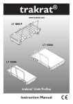
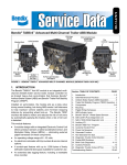
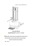
MoniMax7600I
Installation Manual
Copyrightⓒ 2010 Nautilus Hyosung Inc. All right reserved
MoniMax7600I
Installation Manual
Revision Record
Date
Page
Version
May 2010
All
1.0
June 2010
12~13
22~23
1.1
Description of Change
New Publication
Modifying AC Inlet Box.
Adding how to install the topper on the ATM.
2
MoniMax7600I
Installation Manual
Table of Contents
Introduction
························································································································· 4
Warning Signs
Common precautions for safety ····················································································· 5
Description of Warning signs ························································································· 6
System Configuration
ATM Components ·············································································································· 8
ATM Dimensions ·············································································································· 9
Terminal Block Interface ······························································································· 11
AC Inlet Box
Function ·························································································································· 13
Block Diagram ················································································································ 13
Configuration ··················································································································· 13
Input Specification ········································································································· 14
Power Cable
················································································································· 14
System Installation
How to unpack and move the MoniMax7600I into position ········································ 15
Packing Dimensions ······································································································ 16
Installation Condition and Space ··················································································· 17
Placement of the MoniMax7600I ATM ·········································································· 18
Installation and Service Clearance ··············································································· 19
Anchor Diagram ············································································································· 22
Topper Installation ········································································································· 23
Precautions
······················································································································ 26
3
MoniMax7600I
Installation Manual
Introduction
The MoniMax7600I ATM is a fully automated, stand-alone, drive-up terminal which can perform a
wide range of self-service transactions.
Consumers can carry out transactions, receive paper currency and transaction records (statements
and receipts).
The MoniMax7600I ATM is installed on a new or existing concrete island. The terminal is weathersealed to allow for exposure to the weather.
This manual is designed to provide installation guide for the MoniMax7600I ATM and provide
detailed description of the following:
- Information for installation
- Environmental Specification
- Power Specification
All measurements in this manual are in metric and U.S. standards. Metric measurements are first,
U.S. measurements are second and in parentheses.
All information described in this manual is a licensed product of Nautilus Hyosung Corporation.
It is the policy of Nautilus Hyosung Corporation to improve products as new technology, components,
software, and firmware become available. Therefore Nautilus Hyosung reserves the right to change
specifications without notice.
4
MoniMax7600I
Installation Manual
Warning Signs
Common Precautions for Safety
Precautions outlined this manual provide information on safe and proper
handling of the product. Non-compliance of the precautions may result
in injury or damage to the product.
This precaution symbol with sample term tells you safety warnings during
equipment handlings.
Please read the following instructions before operating equipment.
z Operate equipment in the order outlined in this manual.
z Follow precautions indicated in this manual, as well as the equipment itself.
Failure to properly address these precautions may lead to injury or damage to
the product.
z Avoid operations not addressed in this manual.
z If you cannot remedy system problems using the methods outlined in this manual,
please refer to contact information listed in the manual.
z Any change or modifications in construction of this device which are not expressly approved
by the party responsible for compliance could void the user’s authority to operate the equipment.
NOTE: This equipment has been tested and found to comply with the limits for a Class A digital
device, pursuant to part 15 of the FCC Rules. These limits are designed to provide reasonable
protection against harmful interference when the equipment is operated in a commercial
environment. This equipment generates, uses, and can radiate radio frequency energy and, if not
installed and used in accordance with the instruction manual, may cause harmful interference to
radio communications. Operation of this equipment in a residential area is likely to cause harmful
interference in which case the user will be required to correct the interference at his own expense.
5
MoniMax7600I
Installation Manual
Description of Warning Signs
Sign
Description
Risk Of Electric Shock
• Do not remove cover. Only a maintenance engineer should open the cover.
• To avoid risk of electric shock, do not touch.
• Make sure to turn off the power before servicing the equipment.
Hot Surface
• Do not touch the equipment when it is on.
• The equipment can get extremely hot and may cause a burn.
• Make sure to close the cover before running the equipment.
Moving
• The equipment is heavy. Make sure at least 2 people lift or move the equipment
• Do not attempt to move the equipment alone. You may be injured from
dropping the heavy equipment
Risk of Injury
• Always lock Push-Plate before adding cash to cassette.
• Refer to user manual for details.
Risk of Injury
• Turn off the machine before performing any service work.
• Use caution to avoid injury
Handling Heavy Equipment
• You may be injured if machine is dropped or mishandled.
• Use caution when moving the machine to avoid injury
Risk of Injury
• Use caution when operating the push-plate to avoid injury.
• The covers should be locked to avoid injury.
• Refer to operating manual before installing the cassette.
6
MoniMax7600I
Installation Manual
Sign
Description
Fire Hazard
• Place the equipment in an area away from any combustible materials.
• The equipment may catch on fire from overheating or short circuit of the power
supply unit.
Disassembly
• Do not disassemble or modify the equipment unless you are a certified engineer.
• Contact the service center for maintenance, adjustments and repairs.
• Improper disassembly may cause fire or electrical shock.
Fall down
• Do not place the equipment where the floor cannot sustain the weight of the
equipment, or on slanted or unstable surface.
• Equipment may fall down and cause injury or damage.
Unplug the Equipment
• Stop using the equipment immediately if it smokes, emits an unusual smell,
makes abnormal sounds, or if liquids or other foreign materials enter the
equipment.
• If the above-mentioned abnormalities occur, immediately turn off the power,
unplug the equipment and contact the service center.
• If you ignore these symptoms, the equipment may catch on fire or cause electric
shock.
CAUTION!!
1. TO REDUCE THE RISK OF FIRE, USE ONLY No. 26 AWG OR LARGER
TELECOMMUNICATION LINE CORD
2. RISK OF EXPLOSION IF BATTERY IS REPLACED BY AN INCORRECT
TYPE.
DISPOSED OF USED BATTERIES ACCORDING TO THE INSTRUCTIONS
3. FOR PLUGGABLE EQUIPMENT, THE SOCKET-OUTLET SHALL BE INSTALLED NEAR
THE EQUIPMENT AN SHALL BE EASILY ACCESSIBLE
4. THE EQUIPMENT IS TO BE SECURED TO THE BUILDING STRUCTURE BEFORE
OPERATION
7
MoniMax7600I
Installation Manual
System Configuration
ATM Components
..1
..7
..2
..8
..3
..9
..4
..10
..11
..5
..12
..6
Fig.1 MoniMax7600I Components
1
ATM Signage & Logo
7
Receipt Printer Slot
2
Statement Printer (Option)
8
Encryption PIN Pad
3
Tilting Screen Control Buttons
9
Envelope Stacker (BCA/CSM Upgradeable)
4
Customer Display (Touch or Function key)
10
Card Reader Slot
5
Cash Dispenser Slot
11
Envelope Depositor Slot (BNA Upgradeable)
6
Car Detection sensor
12
Front Door Key
8
MoniMax7600I
Installation Manual
ATM Dimensions
Dimension on Front View
Fig.2 ATM Dimensions on front
9
MoniMax7600I
Installation Manual
Dimension on Side View
Fig.3 ATM Dimensions on side
10
MoniMax7600I
Installation Manual
Terminal Block Interface
Terminal Block Interface (1)
Fig.4 Terminal Block Interface (1)
11
MoniMax7600I
Installation Manual
Terminal Block Interface (2)
Fig.5 Terminal Block Interface (2)
12
MoniMax7600I
Installation Manual
AC Inlet Box
Function
Secure the stability during AC power input and system operation and distribute the AC power evenly.
Block Diagram
* AC Inlet Box Specification: 110 Vac 20A
Fig.6 Block Diagram
Configuration
NOTE1 - Terminal Block : AC Inlet of the AC Inlet Box. (Due to the electrical shock hazard, be sure
to connect Power code to AC Inlet Box after removing the Power Cable Plug from AC Source.)
NOTE2 - Circuit Protector : If the over current occurs in the system, block the power to prevent the
13
MoniMax7600I
Installation Manual
system damage.
NOTE3 - Surge Protector : Prevent the system damage from inflow of high voltage such as
thunderbolt. (AC Free Voltage can be inputted.)
NOTE4 - Multi Outlet : Distribute AC Power to each system power.
Input Specification
The ATM can operate from the following input mains voltages:
● 100-127Vac at 50/60Hz
The maximum current requirements at the stated input voltages are:
● 20A Max at 100Vac
The maximum inrush current requirements at the stated input voltages are:
● 60A peak at 100Vac
NOTE:
1. Power to the ATM is to be a dedicated 20A service.
2. The ATM must comply with local code requirements and be protected with a
30A Circuit Protector.
3. AC Inlet Box is optimized as above description, therefore, be sure not to install the unit
with exceed capacity additionally.
4. The Total amount of each units should not exceed the above AC Inlet Box specification,
Power Cable
The ATM is a fixed wire product and is NOT supplied with a power cable. The ATM is connected to a
dedicated 20A circuit via a terminal block connector.
Be sure to check the polarity written on the terminal block of AC Inlet Box and connect the power
cable. (cf. N – White Wire, L – Black Wire, F.G – Green/Yellow Wire)
WARNING!!
1. The cable used to connect to the ATM must have copper conductors and must comply with local
code requirements.
2. This equipment must be grounded (earthed).
3. Allowable current of the system is 20A. So, if you use the power cable with small capacity, do not
operate all three heaters.
14
MoniMax7600I
Installation Manual
System Installation
How to unpack and move the MoniMax7600I into position
Unpack the machine on top of the palette.
● Cut the straps that are fastened around the box with a knife. (refer to Fig.7)
(Be careful when cutting the straps.)
● Use an appropriate tool to remove the nails from the palette. (refer to Fig.8)
● Remove the lid, then box from the top. Do not discard the packaging materials until you have verified
any shipping damage claim. Contact your distributor immediately if you see any shipping damage.
Store the box in a safe place to re-use or discard of appropriately.
● Verify the contents carefully with the packing list to be sure all items listed are included. Notify your
distributor of any shortages.
●If only the palette needs to be removed, lift the whole machine from the bottom and set it aside.
Fig.7
Fig.8
15
MoniMax7600I
Installation Manual
[WARNING!!]
● Because of the weight and the size of the MoniMax7600I, you need qualified heavy
equipment movers to move the MoniMax7600I ATM to its final position. Persons who are
not qualified to move heavy equipment are risking severe injury if they attempt to move the
MoniMax7600I ATM.
● Handle the MoniMax7600I ATM with care when moving it. Do not move the ATM with either
the safe door or top chassis open. Ensure that the safe door and top chassis are closed
and locked. Keep the ATM upright and do not tilt it.
Packing Dimensions
In some cases it may be necessary to store the ATM (in its box) before it is installed. See Fig.9 for
information on the dimensions and weight of a boxed MoniMax7600I ATM.
Fig.9 Boxed ATM Dimensions
16
MoniMax7600I
Installation Manual
NOTE:
Approximate weight of a boxed MoniMax7600I ATM is 2755lbs (1250Kg). Actual weight will vary
depending on ATM component configuration.
1
1800 mm (70.87 inches)
2
1300 mm (51.18 inches)
3
1170 mm (46.0 inches)
Installation Condition and Space
Following conditions should be met before installing equipment.
● Temperature during operation should be between -35°C ~ +40°C
● Relative humidity should be between 15% ~ 100%.
● Avoid locations where intense direct light is reflected off the LCD screen.
● Avoid locations where strong static electricity can occur.
● The floor must allow easy wheelchair access from the front or the side.
● Space required for servicing the machine should be considered before installation.
NOTE :
1. A canopy is recommended for the convenience of consumers, optimum performance, and ease of
servicing.
2. When you determine the location of your MoniMax7600I ATM, ensure that the physical
environment, including the temperature and humidity, meets the requirements. T
3. Environmental specification, dimension and weight below:
Temperature Range
Operating
Maximum temperature
change rate
Temperature Range
Storage
Maximum temperature
change rate
-35°C ~ +40°C (-31°F ~ 104°F)
-10°C / hour (14°F / hour)
-10°C ~ 50°C (14°F ~ 122°F)
15°C /hour (59°F /hour)
Operating
Relative Humidity
15% ~ 100%
Storage
Relative Humidity
10% ~ 90%
Dimension (HXWXD)
62.64"(1591mm) x 41.26"(1048mm) x 37.40"(950mm)
17
MoniMax7600I
Installation Manual
Weight
1. Standard (with EDU-P): 2755lbs(1250Kg)
2. Option (with BNA): 2910lbs(1320Kg)
Placement of the MoniMax7600I ATM
The MoniMax7600I ATM can be placed on a new or existing concrete island (Fig.10).
..1
..2
..3
Fig.10 Placement of the MoniMax7600I ATM
1
MoniMax7600I ATM
2
Guard posts (4)
3
New or existing concrete island
(Concrete island to be flat and level in area of ATM.)
18
MoniMax7600I
Installation Manual
Installation and Service Clearance
Following diagram is describing the areas required for installing and servicing the MX7600I
19
MoniMax7600I
Installation Manual
120.0°
120.0°
Fig.11 (a) Service Clearance for the MoniMax7600I ATM: Service Position - Plan View
Fig.11 (b) Service Position - Front View
20
MoniMax7600I
Installation Manual
125.0°
Fig.11 (c) Service Position - Side View
21
MoniMax7600I
Installation Manual
Anchor Diagram
22
MoniMax7600I
Installation Manual
Topper Installation
The following procedures detail how to install the topper on the ATM.
● Insert the lower front door key into the lock on the lower front door.
● Turn the key clockwise and open the lower front door.
● Then open the upper front panel pulling it upward.
23
MoniMax7600I
Installation Manual
● There is a topper cover inside the ATM.
● Remove 3 nuts around the topper cover through inside the ATM using nut driver.
Nut Driver
● Then remove topper cover and install the topper on the ATM.
Insert the topper cable into the
hole which is shown after
removing topper cover to install
the topper.
24
MoniMax7600I
Installation Manual
ATM Signage
Be supposed to paste the decoration label on the light, where the bank logo or advertisement is
printed.
Decorate Label where the
bank logo or advertisement
is printed.
Dimension of ATM Signage
Fig.13 ATM Signage Dimension
25
MoniMax7600I
Installation Manual
PRECAUTIONS
MX7600I has system battery back up units as optional itself to grantee customers transaction
safety when losing power status. This function will proceed automatic safe shut down either.
But we are recommending to use UPS system for power sourcing to ATM.
This is basic requirements before turn on the system.
● Check the OUTPUT voltage of power source before inserting ATM power cable into it.
● Dispatch all the unit holder tapes and a desiccant pack form ATM
● This machine should be connected to a dedicated power circuit.
This circuit must consist of LINE, NEUTRAL and GROUND leads connected directly to the power
circuit breaker panel. This circuit cannot be shared with any other equipment.
● Make sure that the outlet of power at installation site should be grounded by using of meter.
It is ok that the voltage measurement between mutual and ground lead in outlet is less than 5.0V
● You can find out that there are 2 types of cables outside the safe door.
- Main Power Supply Cable
- Communication cable.
● Connect power cables and communication cable properly.
WARNING!!
1. You must provide an electrical circuit with a third-wire grounding conductor. A machine
without a ground connection is a safety hazard and will not work correctly.
2. To avoid the risk of severe personal injury or death, use only a qualified electrical
contractor to perform work on electrical circuits.
26