1
ORCA Series 4 FPGA
Configuration
April 2002
Technical Note TN1013
Introduction
Configuration is the process of loading a design via a bitstream file into the FPGA internal configuration memory.
Readback is the process of reading the configuration data in a programmed FPGA back out, into a file.
This application note is segmented into three main sections: Configuration Modes, Bit Generation Options, and
Configuration Process and Flow. The Configuration Modes Section shows all the different modes with schematic
diagrams, functional timing waveforms, and descriptions. The Bit Generation Options section describes the options
available when creating a bitstream file with the ORCA Foundry software program bitgen; this section also shows
the configuration frame format and content. The Configuration Process and Flow section details the states of operation of the device during configuration, miscellaneous configuration options, configuration frame sizes, and bitstream file error responses.
This document does not contain any configuration performance timing numbers for devices. Refer to the ORCA
Series 4 Data Sheet for timing numbers.
Configuration Modes
The ORCA Series FPGA functionality is determined by the state of internal configuration RAM. This configuration
RAM can be loaded in a number of different modes. In these configuration modes, the FPGA can act as a master
or a slave of other devices in the system. The decision as to which configuration mode to use is a system design
issue. Configuration is discussed in detail, including the configuration data format and the configuration modes
used to load the configuration data in the FPGA, throughout this document.
There are eleven methods for configuring the FPGA. There are three basic FPGA configuration modes: master,
slave, and peripheral. The configuration data can be transmitted to the FPGA serially or in parallel bytes. As a master, the FPGA provides the control signals out to strobe data in. As a slave device, a clock is generated externally
and provided into the CCLK input. In the three peripheral modes, the FPGA acts as a microprocessor peripheral.
There are two different configuration speeds for the master and asynchronous peripheral modes, controlled by an
internal oscillator. The nominal frequencies of the internal oscillator are 1.25 MHz and 10 MHz. Note that these are
nominal values and the actual range of frequencies obtained from the internal oscillator are wide. Table 1 lists the
functions of the configuration mode pins.
Table 1. Configuration Modes
Configuration Mode
M3
M2
M1
M0
CCLK
Data
Master Serial
0
0
0
0
Output. 10 MHz
1-bit
Master Parallel
0
1
0
0
Output. 10 MHz
8-bit
Asynchronous Peripheral
0
1
0
1
Output. 10 MHz
8-bit
Master Serial
1
0
0
0
Output. 1.25 MHz.
1-bit
Slave Parallel
1
0
0
1
Input.
8-bit
MPI 8-bit
1
0
1
0
Output.
8-bit
MPI 16-bit
1
0
1
1
Output.
16-bit
Master Parallel
1
1
0
0
Output. 1.25 MHz.
8-bit
Asynchronous Peripheral
1
1
0
1
Output. 1.25 MHz.
8-bit
MPI 32-bit
1
1
1
0
Output.
32-bit
Slave Serial
1
1
1
1
Input.
1-bit
www.latticesemi.com
1
tn1013_01
Lattice Semiconductor
ORCA Series 4 FPGA Configuration
Master Parallel Mode
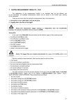
The master parallel configuration mode is generally used to interface to industry-standard, byte-wide memory. Figure 1 provides the connections for master parallel mode. The FPGA outputs an 18-bit address on A[17:0] to memory and reads 1 byte of configuration data on the rising edge of RCLK, which is driven by the FPGA for optional
monitoring. The parallel bytes are internally serialized starting with the least significant bit, D0. Databus D[7:0] of
the FPGA can be connected to databus D[7:0] of the microprocessor if a standard PROM file format is used. If a
.bit or .rbt file is used from ORCA Foundry, then the user may need to mirror the bytes in the .bit or .rbt file. See the
Byte Mirror switch description under the Bitstream Generation (BitGen) Software Switches and Options section for
more details on byte mirroring.
Figure 1. Master Parallel Configuration Schematic
DOUT
A[21:0]
A[21:0]
D[7:0]
D[7:0]
EPROM
TO DAISYCHAINED
DEVICES
CCLK
ORCA
SERIES
FPGA
OE
DONE
CE
PRGM
M2
PROGRAM
VDD
VDD or GND
HDC
M1
LDC
M0
RCLK
In master parallel mode, the starting memory address is 00000 Hex, and the FPGA increments the address for
each byte loaded. One master FPGA can interface to the memory and provide configuration data on DOUT to additional FPGAs in a daisy-chain. The configuration data on DOUT is provided synchronously with the rising edge of
CCLK. The frequency of the CCLK output is eight times that of RCLK. The timing diagram for Master Parallel configuration is shown in Figure 2.
Figure 2. Master Parallel Configuration Timing Diagram
A[17:0]
RCLK
D[7:0]
BYTE N + 1
BYTE N
CCLK
DOUT
D0
2
D1
D2
D3
D4
D5
D6
D7
Lattice Semiconductor
ORCA Series 4 FPGA Configuration
Master Serial Mode
In the master serial mode, the FPGA loads the configuration data from an external serial ROM. The configuration
data is either loaded automatically at start-up or on a PRGM command to reconfigure. Serial PROMs can be used
to configure the FPGA in the master serial mode.
Configuration in the master serial mode can be done at power-up and/or upon a configure command. The system
or the FPGA must activate the serial ROM's RESET/OE and CE inputs. At powerup, the FPGA and serial ROM
each contain internal power-on reset circuitry that allows the FPGA to be configured without the system providing
an external signal. The power-on reset circuitry causes the serial ROM's internal address pointer to be reset. After
powerup, the FPGA automatically enters its initialization phase.
The serial ROM/FPGA interface used depends on such factors as the availability of a system reset pulse, avail-ability of an intelligent host to generate a configure command, whether a single serial ROM is used or multiple serial
ROMs are cascaded, whether the serial ROM contains a single or multiple configuration pro-grams, etc. Because
of differing system requirements and capabilities, a single FPGA/serial ROM interface is not appropriate for all
applications.
Data is read in the FPGA sequentially from the serial ROM. The DATA output from the serial ROM is connected
directly into the DIN input of the FPGA. The CCLK output from the FPGA is connected to the CLK input of the serial
ROM. During the configuration process, CCLK clocks one data bit on each rising edge.
Since the data and clock are direct connects, the FPGA/serial ROM design task is to use the system or FPGA to
enable the RESET/OE and CE of the serial ROM(s). There are several methods for enabling the serial ROM’s
RESET/OE and CE inputs. The serial ROM’s RESET/OE is programmable to function with RESET active-high and
OE active-low or RESET active-low and OE active-high. 500 ns low pulse into the FPGA's PRGM input. The
FPGA’s INIT input is connected to the serial ROMs’ RESET/OE input, which has been programmed to function with
RESET active-low and OE active-high.
In Figure 3, serial ROMs are cascaded to configure multiple daisy-chained FPGAs. The host generates a 500 ns
low pulse into the FPGA's PRGM input. The FPGA's INIT input is connected to the serial ROMs' RESET/OE input,
which has been programmed to function with RESET active-low and OE active-high. The FPGA DONE is routed to
the CE pin. The low on DONE enables the serial ROMs. At the completion of configuration, the high on the FPGAs
DONE disables the serial ROM.
Serial ROMs can also be cascaded to support the configuration of multiple FPGAs or to load a single FPGA when
configuration data requirements exceed the capacity of a single serial ROM. After the last bit from the first serial
ROM is read, the serial ROM outputs CEO low and 3-states the DATA output. The next serial ROM recognizes the
low on CE input and outputs con-figuration data on the DATA output. After configuration is complete, the FPGA's
DONE output into CE disables the serial ROMs.
This FPGA/serial ROM interface is not used in applications in which a serial ROM stores multiple configuration programs. In these applications, the next configuration program to be loaded is stored at the ROM location that follows
the last address for the previous configuration program.
In some applications, there can be contention on the FPGA's DIN pin. During configuration, DIN receives configuration data, and after configuration, it is a user I/O. If there is contention, an early DONE at start-up (selected with
the ORCA Foundry bitgen program) may correct the problem. An alternative is to use LDC to drive the serial
ROM's CE pin. In order to reduce noise, it is generally better to run the master serial configuration at 1.25 MHz,
rather than 10 MHz, if possible. The timing diagram for Master Serial configuration is shown in Figure 4.
3
Lattice Semiconductor
ORCA Series 4 FPGA Configuration
Figure 3. Master Serial Configuration Schematic
DATA
DOUT
DIN
CLK
CCLK
CE
RESET/OE
DONE
TO DAISYCHAINED
DEVICES
PRGM
CEO
ORCA
SERIES
FPGA
DATA
CLK
CE
M2
M1
M0
RESET/OE
CEO
TO MORE
SERIAL ROMs
AS NEEDED
PROGRAM
Figure 4. Master Serial Configuration Timing Diagram
CCLK
DIN
BIT N
DOUT
BIT N
4
Lattice Semiconductor
ORCA Series 4 FPGA Configuration
Asynchronous Peripheral Mode
Figure 5 shows the connections needed for the asynchronous peripheral mode. In this mode, the FPGA system
interface is similar to that of a microprocessor-peripheral interface. The microprocessor generates the control signals to write an 8-bit byte into the FPGA. The FPGA control inputs include active-low CS0 and active-high CS1 chip
selects and WR and RD inputs. The chip selects can be cycled or maintained at a static level during the configuration cycle. Each byte of data is written into the FPGA’s D[7:0] input pins. D[7:0] of the FPGA can be connected to
D[7:0] of the microprocessor if a standard PROM file format is used. If a .bit or .rbt file is used from ORCA Foundry,
then the user may need to mirror the bytes in the .bit or .rbt file. See the Byte Mirror switch description under the
Bitstream Generation (BitGen) Software Switches and Options section for more details on byte mirroring.
The FPGA provides an RDY/BUSY status output to indicate that another byte can be loaded. A low on RDY/BUSY
indicates that the double-buffered hold/shift registers are not ready to receive data, and this pin must be monitored
to go high before another byte of data can be written. The shortest time RDY/BUSY is low occurs when a byte is
loaded into the hold register and the shift register is empty, in which case the byte is immediately transferred to the
shift register. The longest time for RDY/BUSY to remain low occurs when a byte is loaded into the holding register
and the shift register has just started shifting configuration data into configuration RAM.
The RDY/BUSY status is also available on the D[7:3] pins by enabling the chip selects, setting WR high, and applying RD low, where the RD input provides an output enable for the D[7:3] pins when RD is low. The D[2:0] pins are
not enabled to drive when RD is low and, therefore, only act as input pins in asynchronous peripheral mode.
Optionally, the user can ignore the RDY/BUSY status and simply wait until the maximum time it would take for the
RDY/BUSY line to go high, indicating the FPGA is ready for more data, before writing the next data byte. The timing
diagram Asynchronous Peripheral configuration is shown in Figure 6.
Figure 5. Asynchronous Peripheral Configuration
DOUT
PRGM
D[7:0]
RDY/BUSY
INIT
DONE
8
CCLK
MICROPROCESSOR
ADDRESS
DECODE LOGIC
CS0
CS1
BUS
CONTROLLER
RD
WR
VDD
M2
ORCA
SERIES
FPGA
HDC
M1
M0
5
LDC
TO DAISYCHAINED
DEVICES
Lattice Semiconductor
ORCA Series 4 FPGA Configuration
Figure 6. Asynchronous Peripheral Configuration Timing Diagram
CS0
CS1
WR
D[7:3]
WRITE DATA
RD
RDY
CCLK
DOUT
PREVIOUS BYTE
D7
6
D0
D1
D2
D3
Lattice Semiconductor
ORCA Series 4 FPGA Configuration
Microprocessor Interface Mode
The built-in microprocessor interface (MPI) in Series 4 FPGAs is designed for use in configuring the FPGA. Figure
7 shows the glueless interface for FPGA configuration and readback from a PowerPC processor.
Figure 7. MPI Configuration Schematic
DOUT
CCLK
8, 16, 32
D[0:#]
A[14:31]
CLKOUT
RD/WR
TA
POWERPC
BDIP
IRQx
TS
D[0:#]
A[0:17]
MPI_CLK
MPI_RW
ORCA
MPI_ACK
SERIES 4
MPI_BDIP FPGA
MPI_IRQ
MPI_STRB
DONE
CS0
INIT
CS1
HDC
LDC
TO DAISYCHAINED
DEVICES
BUS
CONTROLLER
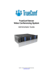
In general, a PROM image of the configuration bitstream is generated in EXO (S-record) or MCS (Intel *) format
and linked into the firmware image during the compilation process. At power-up, the ORCA device examines the
MODE pins, activates the MPI, and waits for firmware to write the configuration data into the device. The basic
algorithm for configuring the device via the MPI is presented in Figure 8.
7
Lattice Semiconductor
ORCA Series 4 FPGA Configuration
Figure 8. Configuration Through MPI
Power-up with MODE
pins set for MPC mode
Assert PGRM_MPI in
(0x0009) and then
deassert
Read 0x000C
N
INIT High?
Time-out?
N
Error
Y
Y
1 ms Time Delay
Set control bits for
SYS_DAISY and/or
USR_ENABLE. Set data
word counter + 4 pad words
Initialize EBR memory
N
Read 0x000C and 0x000D
Error
Write data words to
0x001C. Pad end
till DONE
Time-out?
Y
N
N
N
DONE High?
ERR_FLAG?
Y
Y
Done
Error
CFG_ACK?
N
Y
Data word
counter = 0
Y
Error
If a configuration error occurs during the configuration process, the INIT signal is forced low, the DONE pin will not
go high, and the error flags bits are set in the status registers (0x0000C, 0x0000D). The firmware must assert
PGRM_MPI (0x00009) to reinitialize the configuration logic before attempting to reconfigure the device.
A device ID error indicates that firmware attempted to load a bitstream that was generated for an FPGA other than
the target device. A checksum error is generated if correct framing is detected, but one or more bits in the bitstream
are corrupted. A framing/alignment error occurs most often when the data bits are reversed in the bitstream generation or firmware compilation processes. Another common indication of this is that the complete bitstream is sent
8
Lattice Semiconductor
ORCA Series 4 FPGA Configuration
without errors, but DONE does not go high even after several dummy bytes are written into the configuration data
register (e.g., the start of frame sequence was never detected).
During configuration, initialization errors on the internal system bus are logged in the status register, but they do not
prevent the configuration process from attempting to be completed. The first address of a failure is captured in the
bus error address register (0x00024). If bus errors occur, the system may appear to be functioning, but block RAM
or FPSC control elements may not have been properly initialized. It is left to the FPGA designer to determine if bus
initialization errors during configuration can be tolerated by the design.
The control and status registers are part of the microprocessor interface embedded in the FPGA. Please refer to
the ORCA Series 4 Microprocessor Interface System Bus technical note for the register mapping, addressing, and
descriptions of these registers.
Slave Serial Mode
The slave serial mode is primarily used when multiple FPGAs are configured in a daisy-chain (see the DaisyChaining section). It is also used on the FPGA evaluation board that interfaces to a download cable. A device in the
slave serial mode can be used as the lead device in a daisy-chain. Figure 9 shows the connections for the slave
serial configuration mode.
The configuration data is provided into the FPGA’s DIN input synchronous with the configuration clock CCLK input.
After the FPGA has loaded its configuration data, it retransmits the incoming configuration data on DOUT. CCLK is
routed into all slave serial mode devices in parallel.
Multiple slave FPGAs can be loaded with identical configurations simultaneously. This is done by loading the configuration data into the DIN inputs in parallel. The timing diagram for Slave Serial configuration is shown in Figure
10.
Figure 9. Slave Serial Configuration Schematic
DOUT
INIT
MICROPROCESSOR
OR
DOWNLOAD
CABLE
PRGM
DONE
ORCA
SERIES
FPGA
CCLK
DIN
VDD
M2
M1
M0
HDC
LDC
9
TO DAISYCHAINED
DEVICES
Lattice Semiconductor
ORCA Series 4 FPGA Configuration
Figure 10. Slave Serial Configuration Timing Diagram
DIN
BIT N
CCLK
DOUT
BIT N
Slave Parallel Mode
The slave parallel mode is essentially the same as the slave serial mode except that 8 bits of data are input on pins
D[0:7] for each CCLK cycle. Due to 8 bits of data being input per CCLK cycle, the DOUT pin does not contain a
valid bit stream for slave parallel mode. As a result, the lead device cannot be used in the slave parallel mode in a
daisy-chain configuration.
Figure 11 is a schematic of the connections for the slave parallel configuration mode. WR and CS0 are active-low
chip select signals, and CS1 is an active-high chip select signal. These chip selects allow the user to configure multiple FPGAs in slave parallel mode using an 8-bit data bus common to all of the FPGAs. These chip selects can
then be used to select the FPGAs to be configured with a given bit stream. The chip selects must be active for each
valid CCLK cycle until the device has been completely programmed. They can be inactive between cycles but must
meet the setup and hold times for each valid positive CCLK. D[0:7] of the FPGA can be connected to D[0:7] of the
microprocessor if a standard PROM file format is used. If a .bit or .rbt file is used from ORCA Foundry, then the
user may need to mirror the bytes in the .bit or .rbt file. See the Byte Mirror switch description under the Bitstream
Generation (BitGen) Software Switches and Options section for more details on byte mirroring. The timing diagram
for Slave Serial configuration is shown in Figure 12.
Figure 11. Slave Parallel Configuration Schematic
8
D[0:7]
DONE
INIT
MICROPROCESSOR
OR
SYSTEM
CCLK
PRGM
ORCA
SERIES
FPGA
VDD
CS1
CS0
WR
M2
HDC
M1
LDC
M0
10
Lattice Semiconductor
ORCA Series 4 FPGA Configuration
Figure 12. Slave Parallel Configuration Timing Diagram
CS0
CS1
WR
CCLK
D[7:0]
Daisy-Chaining
Multiple FPGAs can be configured by using a daisy-chain of the FPGAs. Daisy-chaining uses a lead FPGA and
one or more FPGAs configured in slave serial mode. The lead FPGA can be configured in any mode except slave
parallel mode. (Daisy-chaining is available with the boundary-scan ram_w instruction and is discussed later.)
All daisy-chained FPGAs are connected in series. Each FPGA reads and shifts the preamble and length count in
on positive CCLK and out on negative CCLK edges.
An upstream FPGA that has received the preamble and length count outputs a high on DOUT until it has received
the appropriate number of data frames so that downstream FPGAs do not receive frame start bit pairs. After loading and retransmitting the preamble and length count to a daisy-chain of slave devices, the lead device loads its
configuration data frames. The loading of configuration data continues after the lead device has received its configuration data if its internal frame bit counter has not reached the length count. When the configuration RAM is full
and the number of bits received is less than the length count field, the FPGA shifts any additional data out on
DOUT.
The configuration data is read into DIN of slave devices on the positive edge of CCLK, and shifted out DOUT on the
negative edge of CCLK. Figure 13 shows the connections for loading multiple FPGAs in a daisy-chain configuration.
The generation of CCLK for the daisy-chained devices that are in slave serial mode differs depending on the configuration mode of the lead device. A master parallel mode device uses its internal timing generator to produce an
internal CCLK at eight times its memory address rate (RCLK). The asynchronous peripheral mode device outputs
eight CCLKs for each write cycle. If the lead device is configured in slave mode, CCLK must be routed to the lead
device and to all of the daisy-chained devices.
11
Lattice Semiconductor
ORCA Series 4 FPGA Configuration
Figure 13. Daisy-Chain Configuration Schematic
CCLK
A[17:0]
A[17:0]
EPROM
D[7:0]
D[7:0]
OE
CE
DONE
CCLK
DIN
ORCA
SERIES
FPGA
MASTER
DIN
DOUT
ORCA
SERIES
FPGA
SLAVE 1
VDD
VDD
OR
GND
M2
M1
M0
INIT
HDC
LDC
RCLK
VDD
PRGM
M2
M1
M0
DOUT
ORCA
SERIES
FPGA
SLAVE 2
DONE
PRGM
PROGRAM
CCLK
DOUT
VDD
DONE
INIT
HDC
LDC
RCLK
VDD
PRGM
M2
M1
M0
INIT
HDC
LDC
RCLK
VDD
As seen in Figure 13, the INIT pins for all of the FPGAs are connected together. This is required to guarantee that
powerup and initialization will work correctly. In general, the DONE pins for all of the FPGAs are also connected
together as shown to guarantee that all of the FPGAs enter the start-up state simultaneously. This may not be
required, depending upon the start-up sequence desired.
Daisy-Chaining with Boundary Scan
Multiple FPGAs can be configured through the JTAG ports by using a daisy-chain of the FPGAs. This daisy- chaining operation is available upon initial configuration after powerup, after a power-on reset, after pulling the program
pin to reset the chip, or during a reconfiguration if the JTAG Enable RAM has been set.
All daisy-chained FPGAs are connected in series. Each FPGA reads and shifts the preamble and length count in
on the positive TCK and out on the negative TCK edges.
An upstream FPGA that has received the preamble and length count outputs a high on TDO until it has received
the appropriate number of data frames so that downstream FPGAs do not receive frame start bit pairs. After loading and retransmitting the preamble and length count to a daisy-chain of downstream devices, the lead device
loads its configuration data frames.
The loading of configuration data continues after the lead device had received its configuration read into TDI of
downstream devices on the positive edge of TCK, and shifted out TDO on the negative edge of TCK.
12
Lattice Semiconductor
ORCA Series 4 FPGA Configuration
Bitstream Generation (BitGen) Software Switches and Options
This section describes the settings for bitstream generation performed by the ORCA Foundry software program bitgen.
Bit Generation takes a fully routed Physical Design (ncd file) as input and produces a configuration bitstream (bit
images). The bitstream file contains all of the configuration information from the Physical Design defining the internal logic and interconnections of the FPGA, as well as device-specific information from other files associated with
the target device.
The data in the bitstream can then be downloaded directly into the FPGA’s memory cells or used to generate files
for PROM programming (using a separate program, PROMGEN). Please refer to the ORCA Foundry documentation for details on using PROMGEN. You can run Bit Generation from OFCC or from the command line.
The BitGen options are listed in Table 2 and descriptions for each option follow the table.
Table 2. ORCA Series 4 Specific BitGen Options
Name
Command Line Switch
Default Setting
Selectable Settings
Raw Bits
-b
Not used
None
Mask
-m
Not used
0, 1, 2
Disable DRC
-d
Not used
None
Byte Mirror
-x
Not used
None
Done Pin
-g DONEPIN
Pullup
Pullup, Pullnone
Done Active
-g DONEACTIVE
C1
C1, C2, C3, C4
GSR Inactive
-g GSRINACTIVE
Donein
C1, C2, C3, C4, Donein
Outputs Active
-g OUTPUTSACTIVE
Donein
C1, C2, C3, C4, Donein
Sync to Done
-g SYNCTODONE
No
Yes, No
JTAG Enable
-g JTAG
Disable
Enable, Disable
Oscillator
-g OSCILLATOR
Disable
Enable, Disable, EnableDiv8
Enable I/O during Configuration
-g OUTPUTSCFG
Enable
Enable, Disable
Device Reset
-g RAMCFG
Reset
Reset, No
Readback
-g READBACK
Disable
Disable, Once, Command
Capture Read
-g READCAPTURE
Disable
Disable, Read, UserNet, Both
Register Reset
-g REGISTERCFG
Enable
Enable, Disable
Startup Clock
-g STARTUPCLK
Cclk
Cclk, UserClk
Address
-g ADDRESS
Increment
Increment, Explicit
Zero Frames
-g ZEROFRAMES
Yes
Yes, No
System Bus Reset
-g SysbusCfg
Reset
Reset, NoReset
System Bus Clock Reset
-g SysbusclkCfg
Reset
Reset, NoReset
Wait State Timeout
-g WaitStateTimeout
0
0, 1, 2, .. , 14, 15
Grant Timeout
-g GrantTimeout
0
0, 1, 2, .. , 14, 15
Block RAM Configuration
-r
Not used
<ramfile[.mif]>
JTAG Setup
-J
Not used
-r, -w <infile1.ncd>
{<infile2.ncd>}, -a, -o <outfile>
13
Lattice Semiconductor
ORCA Series 4 FPGA Configuration
Raw Bits (-b)
This switch causes bitgen to create a Raw Bit (rbt) file instead of a binary file (bit). Do not use -b with -m if you want
both a Raw Bits file and a mask file (see the -m mask command below). Instead run BITGEN twice — once with
the -b option and once with the -m option.
The Raw Bit File is a text file containing ASCII ones and zeros representing the bits in the bitstream file. If you are
using a microprocessor to configure a single FPGA, you can include the Raw Bit file in the source code as a text file
to represent the configuration data. The sequence of characters in the Raw Bit file is the same as the bit sequence
that will be written into the FPGA.
Mask (-m)
This switch causes bitgen to create a Mask file (msk) instead of a binary file (bit). The format value option equals
either 0, 1, or 2. The value 0 is the generic format, 1 is design-specific, and 2 is design-specific plus user RAMs.
Each of these formats are explained below.
The Mask file is used to compare relevant bit locations for executing a readback of configuration data contained in
an operating FPGA. The Mask file is an ASCII file with only data frames in it. When user selects mask option in Bit
Generation, Bit Generation will generate a mask file for the input design. There are three different mask file formats. They are all similar in format with slight differences in content.
The mask file will be an ASCII file that has the following format for Series 4:
01[data frame][alignment bits][checksum]11111111
Generic format (format value = 0)
In the data frames, V's will be positioned at the location of every configuration RAM location that is used for the
device and X's will be positioned at the location of every configuration RAM location that is unused for the device.
The alignment bits will be 0's and the checksum is affected by the relative location of any mask bits in a byte of the
frame. If a mask bit (an X) is at bit 2 for the frame, bit 2 at the checksum is masked as an X as well.
Design specific format (format value = 1)
The design specific mask file should be an ASCII file of 1’s and 0’s, and X’s. This file should have the same structure as the Generic mask file except instead of a V in all used configuration RAM locations the actual programming
data should be in the appropriate locations in the data frame. The X’s should be at the locations of the unused configuration RAM as in the Generic file.
Design specific format with masks for user RAM (format value = 2)
This format is also be an ASCII file that follows the format of the design specific file with the addition of X’s in the
locations of PFUs configured as user RAM in the design. This is any RAM block that the user has put in the design
including asynchronous and RAMs.
Disable DRC (-d)
This switch causes bitgen to not run the design rules checker (DRC). Without disabling DRC with this switch, bitgen
will run a physical design rule check and save the output to the Bit Generation report (.bgn file). Running DRC
before a bitstream is produced will detect any errors that could cause the FPGA to function improperly. If no fatal
errors are detected, it will produce a bitstream file.
Byte Mirror (-x)
This switch causes bitgen to perform Byte mirroring, where one byte of data record goes through two conversions
in the following order.
1) Reverse the bit order within each nibble. (i.e. 1011 would become 1101).
14
Lattice Semiconductor
ORCA Series 4 FPGA Configuration
2) Swap each pair of nibbles for every byte. (i.e. 0000 1111 would become 1111 0000).
For example:
Raw Bit file broken up for readability:
1111 1111 1111 0010 0000 0000 1111 1111 1100 1000 1111 1111
Step (1)
1111 1111 1111 0100 0000 0000 1111 1111 0011 0001 1111 1111
Step (2)
1111 1111 0100 1111 0000 0000 1111 1111 0001 0011 1111 1111
Whether to use byte mirroring depends on how the device (i.e. a microprocessor) the data is being downloaded to
manages data. Byte mirroring is not typically used for Motorola microprocessors while byte mirroring is typically
used with Intel microprocessors.
Done Pin
Options are to either Pullup the DONE pin with an internal 100 K ohm resistor or Pullnone, meaning do not use an
internal pullup resistor.
Done Active
This switch selects the event that internally activates the DONE signal.
Settings are C1 (default), C2, C3, C4.
C1 means DONE becomes active at the first CCLK rising edge after the length count is met.
C2 means DONE becomes active at the second CCLK rising edge after the length count is met.
C3 means DONE becomes active at the third CCLK rising edge after the length count is met.
C4 means DONE becomes active at the fourth CCLK rising edge after the length count is met.
GSR Inactive
This switch selects the event that releases the internal, global set/reset on the device’s latches and flip-flops. Settings are C1, C2 , C3, C4, and Donein (default).
C1 means GSR is released at the first CCLK rising edge after the length count is met.
C2 means GSR is released at the second CCLK rising edge after the length count is met.
C3 means GSR is released at the third CCLK rising edge after the length count is met.
C4 means GSR is released at the fourth CCLK rising edge after the length count is met.
Donein means GSR is released when the external DONE signal goes high.
Note: If Doneln is selected for this option, the Sync to Done switch is ignored.
Outputs Active
This switch selects the event that releases the I/O from 3-state condition and turns the configuration-related pins
operational. Settings are C1, C2, C3, C4, and Donein.
C1 means the I/Os are released at the first CCLK rising edge after the length count is met.
C2 means the I/Os are released at the second CCLK rising edge after the length count is met.
C3 means the I/Os are released at the third CCLK rising edge after the length count is met.
C4 means the I/Os are released at the fourth CCLK rising edge after the length count is met.
Donein means the I/Os are released when the external DONE signal goes high.
Note: If Doneln is selected for this option, the Sync to Done switch is ignored.
Sync to Done
This switch selects whether (Yes) or not (No) to synchronize the startup sequence to the external DONE signal.
Note that if DoneIn is selected for GSR Inactive or Outputs Active options, this selection is ignored.
15
Lattice Semiconductor
ORCA Series 4 FPGA Configuration
JTAG Enable
Enables or disables JTAG (boundary scan) after configuration. Settings are Enable and Disable (default). Realize
that the BNDSCAN Macro library element needs to be in the design for boundary scan to function.
Oscillator
Enables the on-chip oscillator after configuration. Options are Enable, Disable (default), and EnableDiv8 (divide the
speed by eight). Realize that the OSCIL Macro library element needs to be in the design for the internal oscillator to
function.
Enable I/O during Configuration
If enabled, this switch directs the bitstream to program the FPGA to drive outputs (not be tristated) during configuration/reconfiguration. The only time this should be enabled is for partial reconfiguration when it is desired to keep
the part operational during reconfiguration, and then care must be taken to ensure that no user outputs are placed
at pins required for configuration. See the ORCA Foundry User’s manual for details on how to use the BitTool program to create bitstream files appropriate for partial reconfiguration.
Device Reset
When this switch is set to Reset, it directs the bitstream to reinitializes the device configuration starts. When this
switch is set to No, it directs the bitstream to program the device to retain the current configuration and allows for
additional bitstream configuration. See the ORCA Foundry User’s manual for details on how to use the BitTool program to create bitstream files appropriate for partial reconfiguration.
Readback
Allows you to extract the configuration data stored in an FPGA in order to verify the configuration. Settings are Disable (default), Once (allow one readback only; after that, readback cannot be invoked again), and Command (multiple readbacks).
In an ORCA device, the Readback and Boundary scan functions share the same output pin RD_DATA/TDO. If both
functions are to be used, the RD_DATA output from Readback can be routed to a different pin (or internally) by
using the ORCA Macro Library element READBK.
Capture Read
This switch enables or disables the capture of logic states into the readback bitstream.
The settings are:
Read — Captures all PFU outputs at the time when a readback is triggered by the RD_CFGN input pin.
UserNet — Captures all PFU outputs under the control of an internal signal. If this option is selected, a signal
must be routed to the CAPT pin of the Macro Library element READBK.
Both — Captures all PFU outputs under both Read and User Net conditions.
Disable — Does not capture the PFU outputs. Default.
Register Reset
When this switch is enabled, the device will reset the PFU registers before configuration. The only time this should
be disabled is for partial reconfiguration when it is desired to keep the part operational during reconfiguration. See
the ORCA Foundry User’s manual for details on how to use the BitTool program to create bitstream files appropriate for partial reconfiguration.
Startup Clock
This switch selects whether to use CCLK or a User clock during startup. If a User clock is needed to synchronize
startup to a system clock, it must be routed to the ORCA Macro Library element STRTUP.
16
Lattice Semiconductor
ORCA Series 4 FPGA Configuration
Address
This switch controls whether the configuration addressing will be in Incremental mode or Explicit mode. With Incremental mode, data frames are written out one after another in increasing addresses.
With Explicit mode, every address frame is written into the bitstream, followed by the data frame for each address.
Explicit mode is good for partial reconfiguration, where only some addresses of the array are to be written.
Figure 14 and Figure 15 show the configuration data format waveforms for Increment mode and Explicit mode.
Table 3 and Table 4 show the configuration format and content independent of addressing mode, for the FPGA
array and for the embedded block RAM.
Figure 14. Configuration Data Format—Increment Mode
CONFIGURATION DATA
CONFIGURATION DATA
0 0 1 0
0 1
PREAMBLE LENGTH
COUNT
ID FRAME
0 0
0 1
CONFIGURATION
DATA FRAME 1
CONFIGURATION
DATA FRAME 2
POSTAMBLE
CONFIGURATION HEADER
Figure 15. Configuration Data Format—Explicit Mode
CONFIGURATION DATA
0 0 1 0
PREAMBLE
00
ID FRAME
ADDRESS
FRAME 1
0 1
CONFIGURATION DATA
0 0
CONFIGURATION
DATA FRAME 1
LENGTH CONFIGURATION
COUNT
HEADER
17
0 1
ADDRESS
FRAME 2
0 0
CONFIGURATION
DATA FRAME 2
POSTAMBLE
Lattice Semiconductor
ORCA Series 4 FPGA Configuration
Table 3. FPGA Configuration Frame Format and Contents
Frame
Header
ID Frame
Contents
Description
11110010
Preamble for generic FPGA
24-bit length count
Configuration bitstream length
11111111
8-bit trailing header.
0101 1111 1111 1111
ID frame header
44 reserved bits
Reserved bits set to 0
Part ID
20 bit part ID
Checksum
8 bit checksum
11111111
8 stop bits (high) to separate frames
1111 0010
Mandatory header for generic portion
11111111
8 stop bits (high) to separate frames
00
Address frame header
14-bit address
14-bit address of generic FPGA
Checksum
8-bit checksum
11111111
Eight stop bits (high) to separate frames
01
Data frame header. same as generic.
Alignment bits
String of 0 bits added to frame to reach a byte boundary
Data bits
Number of data bits depends upon device, see Table 6
Checksum
8-bit checksum
11111111
Eight stop bits (high) to separate frames
00 or 10
Postamble header, 00 = finish, 10 = more bits coming
11111111 111111
Dummy address
11111111 11111111
16 stop bits (high)
FPGA Header
FPGA Address
Frame
FPGA Data Frame
Postamble for
Generic FPGA
18
Lattice Semiconductor
ORCA Series 4 FPGA Configuration
Table 4. Block RAM Configuration Frame Format and Contents
Frame
Block RAM Header
Contents
Description
11110001
Mandatory header for RAM bitstream portion
24-bit length count
Configuration bitstream length
11111111
8-bit trailing header.
00
Address frame header
6-bit address
6-bit address of generic FPGA
Checksum
8-bit checksum
11111111
Eight stop bits (high) to separate frames
01
Data frame header. same as generic.
000000
String of six 0 bits added to reach a byte boundary
512 x 18 Data bits
Exact number of bits in a RAM block
Checksum
8-bit checksum
11111111
Eight stop bits (high) to separate frames
00 or 10
Postamble header, 00 = finish, 10 = more bits coming
11111111 111111
Dummy address
11111111 11111111
16 stop bits (high)
Block RAM Address Frame
Block RAM Data Frame
Postamble for Block RAM
Zero Frames
This switch controls whether the bitstream contains null data frames when in Incremental mode. If Yes is selected,
every data fram is written out, including zero data frames, and no address frames are written.
If No is selected, all sequential non-zero data frames are written without address frams and zero data frames are
skipped. When a zero data frame is skipped, the address frame for the next non-zero data frame is written. Selecting No for this switch is good for reducing bitstream size when you know you’ll always do a full configuration from
power up (when all the FPGA is already cleared to zeros).
Selecting No while being in Explicit addressing mode is not allowed. A warning will be generated the ZeroFrames:
No is not compatible with Explicit addressing, and the option will be ignored.
System Bus Reset
When this switch is set to Reset, the System Bus is reset at configuration. If this switch is set to NoReset, the System Bus is not reset at configuration.
System Bus Clock Reset
When this switch is set to Reset, the System Bus Clock is reset at configuration. If this switch is set to NoReset, the
System Bus Clock is not reset at configuration.
Wait State Timeout
This switch controls an internal System Bus timeout counter. Table 5 shows how this switch programs the counter
to timeout after the given number of HCLK cycles goes by while the System Bus is in Wait States. For example, if
the switch is at 5 and the HCLK is running at 50 MHz, the System Bus will timeout after 2^10 * 20 ns ~= 20 microseconds of wait states.
19
Lattice Semiconductor
ORCA Series 4 FPGA Configuration
Table 5. System Bus Timeout Programming
Switch Value
HCLK Cycles
Switch Value
HCLK Cycles
0
Forever (never time out)
8
2^16
1
2^2
9
2^18
2
2^4
10
2^20
3
2^6
11
2^22
4
2^8
12
2^24
5
2^10
13
2^26
6
2^12
14
2^28
7
2^14
15
2^31
Grant Timeout
This switch controls an internal System Bus grant counter. The table for the Wait State Timeout switch above
applies for this switch also, showing how the switch setting programs the counter to timeout after the given number
of HCLK cycles goes by while there is a grant requested on the System Bus.
The Timeout counters provide a way for avoiding a system lockup if something goes wrong on the bus.
Block RAM Configuration
This switch allows the user to specify a separate file for configuring block RAMs in the ORCA Series 4 device. The
file name has to have a .mif (memory initialization file) suffix. The mif file is the same format at used for optional
input into the Scuba program. The mif file consists of lines of address and data. Each line starts with an address,
followed by a colon, and any number of data as shown below. The format of memfile is address: data data data
data ... where address and data are hexadecimal numbers. For example:
A0 : 03 F3 3E 4F
B2 : 3B 9F
The first line puts 03 at address A0, F3 at address A1, 3E at address A2,and 4F at address A3. The second line
puts 3B at address B2 and 9F at address B3. There is no limitation on the values of address and data. No range
checking will be done on addresses to verify that they are valid for the device being configured. All addresses and
data are assumed to be valid and correct You need not specify data at all address locations. If data is not specified
at certain address, the data at that location is initialized to 0.
Block RAM can be initialized the traditional way with SCUBA memory initialization both through the synthesis and
simulation flows. Simulation uses a generic parameter INITVAL, while the synthesis netlist passes an INITVAL
attribute to the synthesis tool to initialize the memory components. This BitGen switch allows another method of initializing Block RAM and also provides a way to partially reconfigure the block RAM with an independent mif file.
See the ORCA Foundry User’s manual for details on how to use the BitTool program to create bitstream files
appropriate for partial reconfiguration.
The easiest way to find out the valid addresses and data for the mif file is to first create the mif files with SCUBA
and then modify them with a text editor if needed.
Block RAM that are configured as multipliers are initialized in the same manner as above, but the mif file is static
and can not be modified and is transparent to the user.
20
Lattice Semiconductor
ORCA Series 4 FPGA Configuration
System bus block RAM will always initialize all block RAMs. Since block memory initialization can be controlled by
multiple methods, an order of precedence is needed in case of conflict. The methods that block memory can be initialized from are:
- Block RAM mif produced by SCUBA
- System bus block RAM mif produced by SCUBA
- Transparent multiplier mif file used for any block RAM based multipliers in a design
- INITVAL attributes in the netlist from SCUBA or HDL
The order of precedence from lowest to highest will be: block RAM .mif file, system bus block RAM .mif file, multiplier .mif file, INITVAL. That is, an INITVAL initialization will take precedence over all other types of initialization, the
multiplier .mif file will take precedence over the system block RAM and block RAM .mif files, etc.
JTAG Setup
JTAG setup. Allows the user to set JTAG port read and write on the FPGA chip by providing them with the setup bitstreams.
Example syntax:
bitgen -J w <infile1.ncd> { <infile2.ncd>}] [-J r] [-a] [-o <outfile>]
where:
-J r generates a JTAG read setup bitstream. The default output is jtagread.jbt.
-J w generates JTAG write setup bitstream.
-a outputs an ASCII file.
-o <outfile> specifies the output file name.
The above example syntax for JTAG setup will generate JTAG write setup bitstream that specifies infile1.ncd as the
target design to be downloaded, so the correct initialization bits will be added to the bitstream. If more than one
design is on the command line, the bitstreams for daisy-chained devices will be generated using JTAG port. The
default output is infile1.jbt.
21
Lattice Semiconductor
ORCA Series 4 FPGA Configuration
Configuration Process and Flow
Prior to becoming operational, the FPGA goes through a sequence of states, including initialization, configuration,
and start-up. Figure 16 outlines these three states.
Figure 16. FPGA States of Operation
POWERUP
– POWER-ON TIME DELAY
INITIALIZATION
– CLEAR CONFIGURATION MEMORY
– INIT LOW, HDC HIGH, LDC LOW
RESET,
INIT,
OR
PRGM
LOW
BIT
ERROR
YES
NO
YES
NO
CONFIGURATION
– M[3:0] MODE IS SELECTED
– CONFIGURATION DATA FRAME WRITTEN
– INIT HIGH, HDC HIGH, LDC LOW
– DOUT ACTIVE
RESET
OR
PRGM
LOW
START-UP
– ACTIVE I/O
– RELEASE INTERNAL RESET
– DONE GOES HIGH
PRGM
LOW
OPERATION
Initialization
Upon power-up, the device goes through an initialization process. First, an internal power-on-reset circuit is triggered when power is applied. When VDD reaches the voltage at which portions of the FPGA begin to operate (2.0
V), the I/Os are configured based on the configuration mode, as determined by the mode select inputs M[3:0]. A
time-out delay is initiated when VDD reaches between 2.7 V to 3.0 V to allow the power supply volt-age to stabilize.
The INIT and DONE outputs are low. At powerup, if VDD does not rise from 2.0 V to VDD in less than 25 ms, the
user should delay configuration by inputting a low into INIT, PRGM, or RESET until VDD is greater than the recommended minimum operating voltage.
At the end of initialization, the default configuration option is that the configuration RAM is written to a low state.
This prevents shorts prior to configuration. As a configuration option, after the first configuration (i.e., at reconfiguration), the user can reconfigure without clearing the internal configuration RAM first. The active-low, open-drain initialization signal INIT is released and must be pulled high by an external resis-tor when initialization is complete. To
synchronize the configuration of multiple FPGAs, one or more INIT pins should be wire-ANDed. If INIT is held low
by one or more FPGAs or an external device, the FPGA remains in the initialization state. INIT can be used to signal that the FPGAs are not yet initialized. After INIT goes high for two internal clock cycles, the mode lines (M[4:0])
are sampled, and the FPGA enters the configuration state.
The high during configuration (HDC), low during configuration (LDC), and DONE signals are active outputs in the
FPGA’s initialization and configuration states. HDC, LDC, and DONE can be used to provide control of external
22
Lattice Semiconductor
ORCA Series 4 FPGA Configuration
logic signals such as reset, bus enable, or PROM enable during configuration. For parallel master configuration
modes, these signals provide PROM enable control and allow the data pins to be shared with user logic signals.
If configuration has begun, an assertion of RESET or PRGM initiates an abort, returning the FPGA to the initialization state. The PRGM and RESET pins must be pulled back high before the FPGA will enter the configuration state.
During the start-up and operating states, only the assertion of PRGM causes a reconfiguration.
In the master configuration modes, the FPGA is the source of configuration clock (CCLK). In this mode, the initialization state is extended to ensure that, in daisy-chain operation, all daisy-chained slave devices are ready. Independent of differences in clock rates, master mode devices remain in the initialization state an additional six
internal clock cycles after INIT goes high.
When configuration is initiated, a counter in the FPGA is set to 0 and begins to count configuration clock cycles
applied to the FPGA. As each configuration data frame is supplied to the FPGA, it is internally assembled into data
words. Each data word is loaded into the internal configuration memory. The configuration loading process is complete when the internal length count equals the loaded length count in the length count field, and the required end
of configuration frame is written.
During configuration, the PIO and PLC latches/FFs are held set/reset and the internal bidirectional (BIDI) buffers
are 3-stated. The combinatorial logic begins to function as the FPGA is configured. Figure 17 shows the general
waveform of the initialization, configuration, and start-up states.
Figure 17. Initialization/Configuration/Start-Up Waveforms
VDD
RESET
PRGM
INIT
M[3:0]
CCLK
HDC
LDC
DONE
USER I/O
INTERNAL
RESET
(gsm)
INITIALIZATION
CONFIGURATION
START-UP
OPERATION
23
Lattice Semiconductor
ORCA Series 4 FPGA Configuration
Start-Up
After configuration, the FPGA enters the start-up phase. This phase is the transition between the configuration and
operational states and begins when the number of CCLKs received after INIT goes high is equal to the value of the
length count field in the configuration frame and when the end of configuration frame has been written. The system
design issue in the start-up phase is to ensure the user I/Os become active without inadvertently activating devices
in the system or causing bus contention. A second system design concern is the timing of the release of global
set/reset of the PLC latches/FFs.
There are configuration options that control the relative timing of three events: DONE going high, release of the
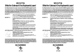
set/reset of internal FFs, and user I/Os becoming active. Figure 18 shows the startup timing for ORCA FPGAs. The
system designer determines the relative timing of the I/Os becoming active, DONE going high, and the release of
the set/reset of internal FFs. In the ORCA Series FPGA, the three events can occur in any arbitrary sequence. This
means that they can occur before or after each other, or they can occur simultaneously.
There are four main startup modes: CCLK_NOSYNC, CCLK_SYNC, UCLK_NOSYNC, and UCLK_SYNC. The
only difference between the modes starting with CCLK and those starting with UCLK is that for the UCLK modes, a
user clock must be supplied to the startup logic. The timing of startup events is then based upon this user clock,
rather than CCLK. The difference between the SYNC and NOSYNC modes is that for SYNC mode, the timing of
two of the startup events, release of the set/reset of internal FFs, and the I/Os becoming active is triggered by the
rise of the external DONE pin followed by a variable number of rising clock edges (either CCLK or UCLK). For the
NOSYNC mode, the timing of these two events is based only on either CCLK or UCLK.
DONE is an open-drain bidirectional pin that may include an optional (enabled by default) pull-up resistor to accommodate wired ANDing. The open-drain DONE signals from multiple FPGAs can be tied together (ANDed) with a
pull-up (internal or external) and used as an active-high ready signal, an active-low PROM enable, or a reset to
other portions of the system. When used in SYNC mode, these ANDed DONE pin-scan be used to synchronize the
other two startup events, since they can all be synchronized to the same external signal. This signal will not rise
until all FPGAs release their DONE pins, allowing the signal to be pulled high.
The default for ORCA is the CCLK_SYNC synchronized startup mode where DONE is released on the first CCLK
rising edge, C1 (see Figure 18). Since this is a synchronized startup mode, the open-drain DONE signal can be
held low externally to stop the occurrence of the other two startup events. Once the DONE pin has been released
and pulled up to a high level, the other two startup events can be programmed individually to either happen immediately or after up to four rising edges of CCLK (Di, Di + 1, Di + 2, Di + 3, Di + 4). The default is for both events to
happen immediately after DONE is released and pulled high.
A commonly used design technique is to release DONE one or more clock cycles before allowing the I/O to
become active. This allows other configuration devices, such as PROMs, to be disconnected using the DONE signal so that there is no bus contention when the I/Os become active. In addition to controlling the FPGA during startup, other startup techniques that avoid contention include using isolation devices between the FPGA and other
circuits in the system, reassigning I/O locations, and maintaining I/Os as 3-stated outputs until contentions are
resolved.
Each of these startup options can be selected during bit stream generation in ORCA Foundry bitgen program, see
the Bitstream Generation (BitGen) Software Switches and Options section of this document for details.
24
Lattice Semiconductor
ORCA Series 4 FPGA Configuration
Figure 18. Start-Up Waveforms
CCLK
PERIOD
ORCA CCLK_NOSYNC
F
DONE
C1
C2
C3
C4
C1
C2
C3
C4
C1
C2
C3
C4
I/O
GSRN
ACTIVE
ORCA CCLK_SYNC
DONE IN
DONE
I/O
F
C1, C2, C3, OR C4
GSRN
ACTIVE
UCLK
Di
Di + 1
Di + 2
Di + 3
Di + 4
Di
Di + 1
Di + 2
Di + 3
Di + 4
ORCA UCLK_NOSYNC
F
DONE
I/O
C1
GSRN
ACTIVE
U1
U2
U3
U4
U1
U2
U3
U4
U1
U2
U3
U4
ORCA UCLK_SYNC
DONE IN
DONE
I/O
C1
Di
GSRN
ACTIVE
F
U1, U2, U3, OR U4
Di + 1
Di + 2
Di + 3
Di Di + 1
Di + 2
Di + 3
Di + 4
UCLK PERIOD
SYNCHRONIZATION UNCERTAINTY
F = FINISHED, NO MORE CLKS REQUIRED.
Reconfiguration
To reconfigure the FPGA when the device is operating in the system, a low pulse is input into PRGM. The configuration data in the FPGA is cleared, and the I/Os not used for configuration are 3-stated. The FPGA then samples
the mode select inputs and begins reconfiguration. When reconfiguration is complete, DONE is released, allowing
it to be pulled high.
Partial Reconfiguration
All ORCA device families have been designed to allow a partial reconfiguration of the FPGA at any time. This is
done by setting a bit stream option in the previous configuration sequence that tells the FPGA to not reset all of the
25
Lattice Semiconductor
ORCA Series 4 FPGA Configuration
configuration RAM during a reconfiguration. Then only the configuration frames that are to be modified need to be
rewritten, thereby reducing the configuration time.
Other bit stream options are also available that allow one portion of the FPGA to remain in operation while a partial
reconfiguration is being done. If this is done, the user must be careful to not cause contention between the two configurations (the bit stream resident in the FPGA and the partial reconfiguration bit stream) as the second reconfiguration bit stream is being loaded.
See the ORCA Foundry User’s manual for details on how to use the BitTool program to create bitstream files
appropriate for partial reconfiguration.
Other Configuration Options
There are many other configuration options available to the user that can be set during bit stream generation in
ORCA Foundry. These include options to enable boundary scan and/or the MPI and/or the programmable PLL
blocks, readback options, and options to control and use the internal oscillator after configuration.
Other useful options that affect the next configuration (not the current configuration process) include options to disable the global set/reset during configuration, disable the 3-state of I/Os during configuration, and disable the reset
of internal RAMs during configuration to allow for partial configurations (see above). For more information on how
to set these and other configuration options, please see the ORCA Foundry documentation.
Configuration Frame Size
Table 6 shows pertinent frame size numbers for each ORCA Series 4 device.
Table 6. Configuration Frame Size
Devices
Number of Frames
Data Bits/Frame
Maximum Configuration Data (Number of bits/frame x Number of frames)
Maximum PROM Size (bits) (add configuration header and postamble)
OR4E2
1796
900
1,610,400
1,161,648
OR4E4
2436
1284
3,127,824
3,128,072
OR4E6
3076
1540
4,737,040
4,737,288
Bit Stream Error Checking
There are three different types of bit stream error checking performed in the ORCA Series 4 FPGAs: ID frame,
frame alignment, and CRC checking. The ID data frame is sent to a dedicated location in the FPGA. This ID frame
contains a unique code for the device for which it was generated. This device code is compared to the internal code
of the FPGA. Any differences are flagged as an ID error. This frame is automatically created by the bit stream generation program in ORCA Foundry.
Each data and address frame in the FPGA begins with a frame start pair of bits and ends with eight stop bits set to
1. If any of the previous stop bits were a 0 when a frame start pair is encountered, it is flagged as a frame alignment
error.
Error checking is also done on the FPGA for each frame by means of a checksum byte. If an error is found on evaluation of the checksum byte, then a checksum/ parity error is flagged. The checksum is the XOR of all the data
bytes, from the start of frame up to and including the bytes before the checksum. It applies to the ID, address, and
data frames.
When any of the three possible errors occur, the FPGA is forced into an idle state, forcing INIT low. The FPGA will
remain in this state until either the RESET or PRGM pins are asserted.
If using either of the MPI modes to configure the FPGA, the specific type of bit stream error is written to one of the
MPI registers by the FPGA configuration logic. The PGRM bit of the MPI control register can also be used to reset
out of the error condition and restart configuration.
26
Lattice Semiconductor
ORCA Series 4 FPGA Configuration
Configuration Pin Buffer Recommendation
Most of the configuration pins are dual use; they are used as configuration pins during configuration, and then are
user IOs at the beginning of operation. It is recommended to not use the new Series 4 IO buffer types on these
dual-use configuration pins.
Configuration is done using default, LVTTL, 3.3V buffers. As configuration is taking place, the buffer will change to
the type specified in the design, which could cause problems. If the design has the configuration pins being
changed to LVDS or LVPECL buffers, configuration will fail. The safest thing to do is to keep all buffers in banks
where there are configuration pins you are using at a level of 3.3V.
27