1
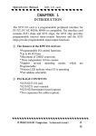
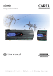
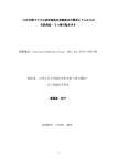
FFT HARMONICS OPTION For instruments type X3M-D, X3M-DH, Flash-D, Flash-DH Instructions manual Page 1 of 18 Index 1. 2 3 4 5 6 7 8 Introduction .............................................................................................................................3 1.1 COPYRIGHT .....................................................................................................................3 Preliminary operations ............................................................................................................3 2.1 Applicable instruments ......................................................................................................3 2.2 Enabling the FFT harmonics option ..................................................................................3 Description ..............................................................................................................................4 Reading selection keys ...........................................................................................................5 4.1 Voltage ..............................................................................................................................5 4.1.1 3P 4W configuration ...................................................................................................5 4.1.2 Other configurations ...................................................................................................5 4.2 Current ..............................................................................................................................6 4.2.1 3P 4W configuration ...................................................................................................6 4.2.2 Other configurations ...................................................................................................6 4.3 Power ................................................................................................................................7 4.3.1 3P 4W configuration ...................................................................................................7 4.3.2 Other configurations ...................................................................................................7 MODBUS Protocol ..................................................................................................................8 5.1 Foreword: ..........................................................................................................................8 5.2 Modbus registers mapping ................................................................................................8 Technical specification ..........................................................................................................15 6.1 Parameters......................................................................................................................15 6.2 Accuracy..........................................................................................................................16 Firmware revisions ................................................................................................................16 Ordering code .......................................................................................................................16 Page 2 of 18 1. Introduction We thank you for choosing Electrex; we invite you to carefully read this instructions manual for the best use of the FFT harmonics option. 1.1 COPYRIGHT Akse S.r.l. All rights are reserved. It is forbidden to duplicate, adapt, transcript this document without Akse written authorization, except when regulated accordingly by the Copyright Laws. Copyright© 2006. 2 Preliminary operations 2.1 Applicable instruments The FFT harmonics option can be implemented only on the instrument types as below indicated: X3M, X3M-D, Flash-N e Flash-D. - The FFT option for these instruments is ordered and supplied separately in the form of an individual PUK code to be used for enabling the option. - Each PUK code is unique and it is individually matched to the instrument serial number the option was ordered for. - The FFT Harmonics option may be used only with instruments bearing a firmware version 2.0 or higher. In the case of lower versions, the firmware must be up-graded; contact Electrex for instructions. X3M-H, X3M DH, Flash-NH and Flash-DH - The FFT harmonics option is supplied together with the instrument. - A label placed on the instrument and marked S/No. ..... H opt PUK….. indicates the individual PUK code to be used for enabling the option. The following instructions apply to the instruments type X3M-D, X3M-DH, Flash-D and FlashDH (DIN rail mount types). 2.2 Enabling the FFT harmonics option Whether ordered separately or supplied with the instrument, the FFT harmonics option needs to be activated by the user by means of a simple PUK code entry as below indicated Enter into the SET-UP mode by pressing the PROGRAM button located in the instrument rear panel (alternatively, by simultaneously pressing the keys). 1) Press the key until the HARMONIC OPT - ENTER PUK page is prompted (see figure). 2) Enter your PUK code into the 00-00-00 fields by pressing the keys to increase/decrease the flashing digit and the key to move to the next digit. - Make sure to enter the PUK code matching the instrument serial number it was issued for. - The PUK code may be composed of numbers and letters in the range 0…..9 A B C D E F. 3) Upon completing the last digit, press the PROGRAM button to confirm and exit the SETUP mode. NB. For the alternative entry into set up mode, the key must be used to confirm and exit. 4) The instrument displays “OPTION ENABLED” to confirm a correct PUK code entry and the permanent enabling of the FFT harmonics option. 5) The “INVALID PUK” message is otherwise displayed to indicate an incorrect entry. Repeat all the entry procedure and ensure to enter a correct PUK code. Page 3 of 18 3 Description The FFT option supports the analyses of voltage and current waveforms up to the 31st order; it provides the individual harmonics readings on display and it enables these readings as Modbus registers on serial line. In addition to voltage and current harmonics it provides the individual readings of harmonics active power with a sign indicating the harmonic origin; negative sign indicating a flow from load to mains, no sign (positive) indicating a flow from mains to load. Thanks to the high calculation power of the instrument, all the harmonics readings, though non-prioritary, up date with an interval of 1 sec (however approximate because influenced by other measurement activities). Accuracy < 1% and sensitivity of 0,5% are figures that validate an especially high performance (particularly when comparing to similar industrial instruments) and that make possible the calculation of power and the determination of flow for the most significant harmonics. Voltage harmonics are generally very low and, consequently, the harmonics powers turn to be infinitesimal values of the fundamental power and quite difficult to calculate. For these reasons and being not possible to ensure accuracy, the harmonics powers readings must be understood as indicative values. The power readings are set to zero and the sign disappear whenever the harmonic powers attain values considered not consistent. The readings of voltage and current of the fundamental waveform are expressed in Volt and Ampere; the phase angle (available only on Modbus registers) is expressed in degrees with respect to the L1 voltage. The readings of voltage and current of the higher harmonics orders are expressed in percentage of their fundamentals. The phase angle (available only on Modbus registers) is expressed in degrees with respect to the L1 voltage. The conversion is made on 64 samples corresponding to one cycle of the 3 voltage and 3 current signal then an FFT calculation (Fast Fourier Transform) is executed. It operates in asynchronous mode with respect to the other readings by analysing a group of 64 samples every measurement cycle corresponding to approximately 1 sec. Page 4 of 18 4 Reading selection keys The parameter category selection is operated by means of the following keys: Voltage and frequency readings Power readings. Energy readings. Current readings Power factor readings. Life time reading. keys, then, scroll the several reading pages up/down within each parameter category. The key is not used for readings display. The 4.1 Voltage Voltage harmonics readings are available within the Several pressures of the key. key scroll the voltage parameters pages; namely: st - a 1 page with phase-neutral voltages and average 3-phase system voltage. - a 2nd page with phase-neutral voltages and frequency. In the above two situations, further pressures of the keys, prompt consecutively: - phase-phase voltages and average phase-neutral system voltage and - total harmonic distortion (THD-V) per phase - a 3rd page, identified by the symbols H V on top, with the readings of harmonics order 01 (fundamental). In this situation, further pressures of the keys scroll the readings of harmonics orders 02 to 31. When using the bottom row keys for viewing different parameter categories, the instrument always prompts the last selected page within each parameter category. 4.1.1 3P 4W configuration 4.1.2 Other configurations In 3P-4W-BAL configuration, the readings relate to V1 only In 3P 3 W configuration, the readings relate to the three phase-to-phase voltages. In 3P-3W-BAL configuration, the readings relate to V12 only. The display mode follows the logic described in the instructions manual of the base instrument. Page 5 of 18 4.2 Current Current harmonics readings are available within the Several pressures of the key. key scroll the current parameters pages; namely: - a 1st page with phase currents and neutral current. - a 2nd page with phase currents and average three-phase current. In the above situation, further pressure of the - Total Harmonic distortion (THD-I) per phase keys, prompts - a 3rd page, identified by the symbol H I on top, with the readings of harmonic order 01 (fundamental). In this situation, further pressures of the keys scroll the readings of harmonics orders 02 to 31. When using the bottom row keys for viewing different parameter categories, the instrument always prompts the last selected page within each parameter category. 4.2.1 3P 4W configuration 4.2.2 Other configurations In 3P-4W-BAL configuration, the readings relate to I1 only In 3P 3 W configuration, the readings relate to the three line currents. In 3P-3W-BAL configuration, the readings relate to I3 only. The display mode follows the logic described in the instructions manual of the base instrument. Page 6 of 18 4.3 Power Harmonics power readings are available within the Several pressures of the key. key scroll the power parameters pages; namely: - a 1st page with active powers (P) - a 2nd page with reactive powers (Q) - a 3rd page with apparent powers (S) In the above situations, further pressure of the - the rolling average values - the Max Demand values keys, prompt - a 4th page, identified by the symbol H P on top, with the power readings of harmonic order 01 (fundamental). In this situation, further pressures of the keys scroll the readings of harmonics orders 02 to 31. A power value with positive sign (no sign) indicates an harmonic flow from mains to load (import). A power value with “ – “sign indicates an harmonic flow from load to mains (export). NB. The sign detection strictly depends upon the orientation of the CTs. therefore, a proper orientation and wiring of the CTs is ESSENTIAL for a correct sign indication. Please refer to the instrument installation manual for details. When using the bottom row keys for viewing different parameter categories, the instrument always prompts the last selected page within each parameter category. 4.3.1 3P 4W configuration 4.3.2 Other configurations In 3P-4W-BAL configuration, the readings relate to V1 and I1 only In 3P- 3W configuration, the readings of power are not available. In 3P-3W-BAL configuration, the readings of power are not available. The display mode follows the logic described in the instructions manual of the base instrument. Page 7 of 18 5 MODBUS Protocol 5.1 Foreword: The instrument modbus protocol is implemented according to the document “MODBUS Application Protocol Specification V1.1”, available in www.modbus.org . The following “Public functions” are implemented: ((0x04) Read Input Registers 5.2 Modbus registers mapping The data resulting from the FFT calculation of a 64-sample cycle are available simultaneously on serial port communication. For the purpose of a proper data analyses and correlation it is essential to be able to collect the data relating to the same sample. The overall number on input registers, however, exceeds the possibilities of interrogation by a "multiple register" command therefore, in order to allow the possibility of interrogating congruent values, the readings are kept on Hold between one sampling and the successive, and updated in real time only upon interrogation of the L1 voltage fundamental value. This enables to interrogate all registers of the same sample (and hence congruent data) irrelevant the number of queries. Harmonics Value of the fundamentals of the three phase system Addr 400 Type Description Unit Symbol Float IEEE754 UL1 fundamental voltage (H1) V UL1 H1 Float IEEE754 UL2 fundamental voltage (H1) V UL2 H1 Float IEEE754 UL3 fundamental voltage (H1) V UL3 H1 Float IEEE754 IL1 fundamental current (H1) A IL1 H1 Float IEEE754 IL2 fundamental current (H1) A IL2 H1 Float IEEE754 IL3 fundamental current (H1) A IL3 H1 412 Integer 16 bit signed UL1 fundamental voltage phase °/10 UL1 H1φ 413 Integer 16 bit signed UL2 fundamental voltage phase °/10 UL2 H1φ 414 Integer 16 bit signed UL3 fundamental voltage phase °/10 UL3 H1φ 415 Integer 16 bit signed IL1 fundamental current phase angle ± 180.0° (H1) °/10 IL1 H1φ 416 Integer 16 bit signed IL2 fundamental current phase angle ± 180.0° (H1) °/10 IL2 H1φ 417 Integer 16 bit signed IL3 fundamental current phase angle ± 180.0° (H1) °/10 IL3 H1φ 401 402 403 404 405 406 407 408 409 410 411 angle ± 180.0° (H1) angle ± 180.0° (H1) angle ± 180.0° (H1) Page 8 of 18 Harmonics on voltage phase L1 Voltage value as % of the fundamental Phase angle referred to the fundamental of the voltage on phase L1 Addr Type Description Unit Symbol Addr Type Description Unit Symbol 418 Integer H2 voltage ‰ VL1 H2 448 Integer H2 voltage phase angle °/10 VL1 H2φ 419 Integer H3 voltage ‰ VL1 H3 449 Integer H3 voltage phase angle °/10 VL1 H3φ 420 Integer H4 voltage ‰ VL1 H4 450 Integer H4 voltage phase angle °/10 VL1 H4φ 421 Integer H5 voltage ‰ VL1 H5 451 Integer H5 voltage phase angle °/10 VL1 H5φ 422 Integer H6 voltage ‰ VL1 H6 452 Integer H6 voltage phase angle °/10 VL1 H6φ 423 Integer H7 voltage ‰ VL1 H7 453 Integer H7 voltage phase angle °/10 VL1 H7φ 424 Integer H8 voltage ‰ VL1 H8 454 Integer H8 voltage phase angle °/10 VL1 H8φ 425 Integer H9 voltage ‰ VL1 H9 455 Integer H9 voltage phase angle °/10 VL1 H9φ 426 Integer H10 voltage ‰ VL1 H10 456 Integer H10 voltage phase angle °/10 VL1 H10φ 427 Integer H11 voltage ‰ VL1 H11 457 Integer H11 voltage phase angle °/10 VL1 H11φ 428 Integer H12 voltage ‰ VL1 H12 458 Integer H12 voltage phase angle °/10 VL1 H12φ 429 Integer H13 voltage ‰ VL1 H13 459 Integer H13 voltage phase angle °/10 VL1 H13φ 430 Integer H14 voltage ‰ VL1 H14 460 Integer H14 voltage phase angle °/10 VL1 H14φ 431 Integer H15 voltage ‰ VL1 H15 461 Integer H15 voltage phase angle °/10 VL1 H15φ 432 Integer H16 voltage ‰ VL1 H16 462 Integer H16 voltage phase angle °/10 VL1 H16φ 433 Integer H17 voltage ‰ VL1 H17 463 Integer H17 voltage phase angle °/10 VL1 H17φ 434 Integer H18 voltage ‰ VL1 H18 464 Integer H18 voltage phase angle °/10 VL1 H18φ 435 Integer H19 voltage ‰ VL1 H19 465 Integer H19 voltage phase angle °/10 VL1 H19φ 436 Integer H20 voltage ‰ VL1 H20 466 Integer H20 voltage phase angle °/10 VL1 H20φ 437 Integer H21 voltage ‰ VL1 H21 467 Integer H21 voltage phase angle °/10 VL1 H21φ 438 Integer H22 voltage ‰ VL1 H22 468 Integer H22 voltage phase angle °/10 VL1 H22φ 439 Integer H23 voltage ‰ VL1 H23 469 Integer H23 voltage phase angle °/10 VL1 H23φ 440 Integer H24 voltage ‰ VL1 H24 470 Integer H24 voltage phase angle °/10 VL1 H24φ 441 Integer H25 voltage ‰ VL1 H25 471 Integer H25 voltage phase angle °/10 VL1 H25φ 442 Integer H26 voltage ‰ VL1 H26 472 Integer H26 voltage phase angle °/10 VL1 H26φ 443 Integer H27 voltage ‰ VL1 H27 473 Integer H27 voltage phase angle °/10 VL1 H27φ 444 Integer H28 voltage ‰ VL1 H28 474 Integer H28 voltage phase angle °/10 VL1 H28φ 445 Integer H29 voltage ‰ VL1 H29 475 Integer H29 voltage phase angle °/10 VL1 H29φ 446 Integer H30 voltage ‰ VL1 H30 476 Integer H30 voltage phase angle °/10 VL1 H30φ 447 Integer H31 voltage ‰ VL1 H31 477 Integer H31 voltage phase angle °/10 VL1 H31φ Page 9 of 18 Harmonics on current phase L1 Current value as % of the fundamental Phase angle referred to the fundamental of the voltage on phase L1 Addr Type Description Unit Symbol Addr Type Description Unit Symbol 478 Integer H2 current ‰ IL1 H2 508 Integer H2 current phase angle °/10 IL1 H2φ 479 Integer H3 current ‰ IL1 H3 509 Integer H3 current phase angle °/10 IL1 H3φ 480 Integer H4 current ‰ IL1 H4 510 Integer H4 current phase angle °/10 IL1 H4φ 481 Integer H5 current ‰ IL1 H5 511 Integer H5 current phase angle °/10 IL1 H5φ 482 Integer H6 current ‰ IL1 H6 512 Integer H6 current phase angle °/10 IL1 H6φ 483 Integer H7 current ‰ IL1 H7 513 Integer H7 current phase angle °/10 IL1 H7φ 484 Integer H8 current ‰ IL1 H8 514 Integer H8 current phase angle °/10 IL1 H8φ 485 Integer H9 current ‰ IL1 H9 515 Integer H9 current phase angle °/10 IL1 H9φ 486 Integer H10 current ‰ IL1 H10 516 Integer H10 current phase angle °/10 IL1 H10φ 487 Integer H11 current ‰ IL1 H11 517 Integer H11 current phase angle °/10 IL1 H11φ 488 Integer H12 current ‰ IL1 H12 518 Integer H12 current phase angle °/10 IL1 H12φ 489 Integer H13 current ‰ IL1 H13 519 Integer H13 current phase angle °/10 IL1 H13φ 490 Integer H14 current ‰ IL1 H14 520 Integer H14 current phase angle °/10 IL1 H14φ 491 Integer H15 current ‰ IL1 H15 521 Integer H15 current phase angle °/10 IL1 H15φ 492 Integer H16 current ‰ IL1 H16 522 Integer H16 current phase angle °/10 IL1 H16φ 493 Integer H17 current ‰ IL1 H17 523 Integer H17 current phase angle °/10 IL1 H17φ 494 Integer H18 current ‰ IL1 H18 524 Integer H18 current phase angle °/10 IL1 H18φ 495 Integer H19 current ‰ IL1 H19 525 Integer H19 current phase angle °/10 IL1 H19φ 496 Integer H20 current ‰ IL1 H20 526 Integer H20 current phase angle °/10 IL1 H20φ 497 Integer H21 current ‰ IL1 H21 527 Integer H21 current phase angle °/10 IL1 H21φ 498 Integer H22 current ‰ IL1 H22 528 Integer H22 current phase angle °/10 IL1 H22φ 499 Integer H23 current ‰ IL1 H23 529 Integer H23 current phase angle °/10 IL1 H23φ 500 Integer H24 current ‰ IL1 H24 530 Integer H24 current phase angle °/10 IL1 H24φ 501 Integer H25 current ‰ IL1 H25 531 Integer H25 current phase angle °/10 IL1 H25φ 502 Integer H26 current ‰ IL1 H26 532 Integer H26 current phase angle °/10 IL1 H26φ 503 Integer H27 current ‰ IL1 H27 533 Integer H27 current phase angle °/10 IL1 H27φ 504 Integer H28 current ‰ IL1 H28 534 Integer H28 current phase angle °/10 IL1 H28φ 505 Integer H29 current ‰ IL1 H29 535 Integer H29 current phase angle °/10 IL1 H29φ 506 Integer H30 current ‰ IL1 H30 536 Integer H30 current phase angle °/10 IL1 H30φ 507 Integer H31 current ‰ IL1 H31 537 Integer H31 current phase angle °/10 IL1 H31φ Page 10 of 18 Harmonics on voltage phase L2 Voltage value as % of the fundamental Phase angle referred to the fundamental of the voltage on phase L1 Addr Type Description Unit Symbol Addr Type Description Unit Symbol 538 Integer H2 voltage ‰ VL2 H2 568 Integer H2 voltage phase angle °/10 VL2 H2φ 539 Integer H3 voltage ‰ VL2 H3 569 Integer H3 voltage phase angle °/10 VL2 H3φ 540 Integer H4 voltage ‰ VL2 H4 570 Integer H4 voltage phase angle °/10 VL2 H4φ 541 Integer H5 voltage ‰ VL2 H5 571 Integer H5 voltage phase angle °/10 VL2 H5φ 542 Integer H6 voltage ‰ VL2 H6 572 Integer H6 voltage phase angle °/10 VL2 H6φ 543 Integer H7 voltage ‰ VL2 H7 573 Integer H7 voltage phase angle °/10 VL2 H7φ 544 Integer H8 voltage ‰ VL2 H8 574 Integer H8 voltage phase angle °/10 VL2 H8φ 545 Integer H9 voltage ‰ VL2 H9 575 Integer H9 voltage phase angle °/10 VL2 H9φ 546 Integer H10 voltage ‰ VL2 H10 576 Integer H10 voltage phase angle °/10 VL2 H10φ 547 Integer H11 voltage ‰ VL2 H11 577 Integer H11 voltage phase angle °/10 VL2 H11φ 548 Integer H12 voltage ‰ VL2 H12 578 Integer H12 voltage phase angle °/10 VL2 H12φ 549 Integer H13 voltage ‰ VL2 H13 579 Integer H13 voltage phase angle °/10 VL2 H13φ 550 Integer H14 voltage ‰ VL2 H14 580 Integer H14 voltage phase angle °/10 VL2 H14φ 551 Integer H15 voltage ‰ VL2 H15 581 Integer H15 voltage phase angle °/10 VL2 H15φ 552 Integer H16 voltage ‰ VL2 H16 582 Integer H16 voltage phase angle °/10 VL2 H16φ 553 Integer H17 voltage ‰ VL2 H17 583 Integer H17 voltage phase angle °/10 VL2 H17φ 554 Integer H18 voltage ‰ VL2 H18 584 Integer H18 voltage phase angle °/10 VL2 H18φ 555 Integer H19 voltage ‰ VL2 H19 585 Integer H19 voltage phase angle °/10 VL2 H19φ 556 Integer H20 voltage ‰ VL2 H20 586 Integer H20 voltage phase angle °/10 VL2 H20φ 557 Integer H21 voltage ‰ VL2 H21 587 Integer H21 voltage phase angle °/10 VL2 H21φ 558 Integer H22 voltage ‰ VL2 H22 588 Integer H22 voltage phase angle °/10 VL2 H22φ 559 Integer H23 voltage ‰ VL2 H23 589 Integer H23 voltage phase angle °/10 VL2 H23φ 560 Integer H24 voltage ‰ VL2 H24 590 Integer H24 voltage phase angle °/10 VL2 H24φ 561 Integer H25 voltage ‰ VL2 H25 591 Integer H25 voltage phase angle °/10 VL2 H25φ 562 Integer H26 voltage ‰ VL2 H26 592 Integer H26 voltage phase angle °/10 VL2 H26φ 563 Integer H27 voltage ‰ VL2 H27 593 Integer H27 voltage phase angle °/10 VL2 H27φ 564 Integer H28 voltage ‰ VL2 H28 594 Integer H28 voltage phase angle °/10 VL2 H28φ 565 Integer H29 voltage ‰ VL2 H29 595 Integer H29 voltage phase angle °/10 VL2 H29φ 566 Integer H30 voltage ‰ VL2 H30 596 Integer H30 voltage phase angle °/10 VL2 H30φ 567 Integer H31 voltage ‰ VL2 H31 597 Integer H31 voltage phase angle °/10 VL2 H31φ Page 11 of 18 Harmonics on current phase L2 Current value as % of the fundamental Phase angle referred to the fundamental of the voltage on phase L1 Addr Type Description Unit Symbol Addr Type Description Unit Symbol 598 Integer H2 current ‰ IL2 H2 628 Integer H2 current phase angle °/10 IL2 H2φ 599 Integer H3 current ‰ IL2 H3 629 Integer H3 current phase angle °/10 IL2 H3φ 600 Integer H4 current ‰ IL2 H4 630 Integer H4 current phase angle °/10 IL2 H4φ 601 Integer H5 current ‰ IL2 H5 631 Integer H5 current phase angle °/10 IL2 H5φ 602 Integer H6 current ‰ IL2 H6 632 Integer H6 current phase angle °/10 IL2 H6φ 603 Integer H7 current ‰ IL2 H7 633 Integer H7 current phase angle °/10 IL2 H7φ 604 Integer H8 current ‰ IL2 H8 634 Integer H8 current phase angle °/10 IL2 H8φ 605 Integer H9 current ‰ IL2 H9 635 Integer H9 current phase angle °/10 IL2 H9φ 606 Integer H10 current ‰ IL2 H10 636 Integer H10 current phase angle °/10 IL2 H10φ 607 Integer H11 current ‰ IL2 H11 637 Integer H11 current phase angle °/10 IL2 H11φ 608 Integer H12 current ‰ IL2 H12 638 Integer H12 current phase angle °/10 IL2 H12φ 609 Integer H13 current ‰ IL2 H13 639 Integer H13 current phase angle °/10 IL2 H13φ 610 Integer H14 current ‰ IL2 H14 640 Integer H14 current phase angle °/10 IL2 H14φ 611 Integer H15 current ‰ IL2 H15 641 Integer H15 current phase angle °/10 IL2 H15φ 612 Integer H16 current ‰ IL2 H16 642 Integer H16 current phase angle °/10 IL2 H16φ 613 Integer H17 current ‰ IL2 H17 643 Integer H17 current phase angle °/10 IL2 H17φ 614 Integer H18 current ‰ IL2 H18 644 Integer H18 current phase angle °/10 IL2 H18φ 615 Integer H19 current ‰ IL2 H19 645 Integer H19 current phase angle °/10 IL2 H19φ 616 Integer H20 current ‰ IL2 H20 646 Integer H20 current phase angle °/10 IL2 H20φ 617 Integer H21 current ‰ IL2 H21 647 Integer H21 current phase angle °/10 IL2 H21φ 618 Integer H22 current ‰ IL2 H22 648 Integer H22 current phase angle °/10 IL2 H22φ 619 Integer H23 current ‰ IL2 H23 649 Integer H23 current phase angle °/10 IL2 H23φ 620 Integer H24 current ‰ IL2 H24 650 Integer H24 current phase angle °/10 IL2 H24φ 621 Integer H25 current ‰ IL2 H25 651 Integer H25 current phase angle °/10 IL2 H25φ 622 Integer H26 current ‰ IL2 H26 652 Integer H26 current phase angle °/10 IL2 H26φ 623 Integer H27 current ‰ IL2 H27 653 Integer H27 current phase angle °/10 IL2 H27φ 624 Integer H28 current ‰ IL2 H28 654 Integer H28 current phase angle °/10 IL2 H28φ 625 Integer H29 current ‰ IL2 H29 655 Integer H29 current phase angle °/10 IL2 H29φ 626 Integer H30 current ‰ IL2 H30 656 Integer H30 current phase angle °/10 IL2 H30φ 627 Integer H31 current ‰ IL2 H31 657 Integer H31 current phase angle °/10 IL2 H31φ Page 12 of 18 Harmonics on voltage phase L3 Voltage value as % of the fundamental Phase angle referred to the fundamental of the voltage on phase L1 Addr Type Description Unit Symbol Addr Type Description Unit Symbol 658 Integer H2 voltage ‰ VL3 H2 688 Integer H2 voltage phase angle °/10 VL3 H2φ 659 Integer H3 voltage ‰ VL3 H3 689 Integer H3 voltage phase angle °/10 VL3 H3φ 660 Integer H4 voltage ‰ VL3 H4 690 Integer H4 voltage phase angle °/10 VL3 H4φ 661 Integer H5 voltage ‰ VL3 H5 691 Integer H5 voltage phase angle °/10 VL3 H5φ 662 Integer H6 voltage ‰ VL3 H6 692 Integer H6 voltage phase angle °/10 VL3 H6φ 663 Integer H7 voltage ‰ VL3 H7 693 Integer H7 voltage phase angle °/10 VL3 H7φ 664 Integer H8 voltage ‰ VL3 H8 694 Integer H8 voltage phase angle °/10 VL3 H8φ 665 Integer H9 voltage ‰ VL3 H9 695 Integer H9 voltage phase angle °/10 VL3 H9φ 666 Integer H10 voltage ‰ VL3 H10 696 Integer H10 voltage phase angle °/10 VL3 H10φ 667 Integer H11 voltage ‰ VL3 H11 697 Integer H11 voltage phase angle °/10 VL3 H11φ 668 Integer H12 voltage ‰ VL3 H12 698 Integer H12 voltage phase angle °/10 VL3 H12φ 669 Integer H13 voltage ‰ VL3 H13 699 Integer H13 voltage phase angle °/10 VL3 H13φ 670 Integer H14 voltage ‰ VL3 H14 700 Integer H14 voltage phase angle °/10 VL3 H14φ 671 Integer H15 voltage ‰ VL3 H15 701 Integer H15 voltage phase angle °/10 VL3 H15φ 672 Integer H16 voltage ‰ VL3 H16 702 Integer H16 voltage phase angle °/10 VL3 H16φ 673 Integer H17 voltage ‰ VL3 H17 703 Integer H17 voltage phase angle °/10 VL3 H17φ 674 Integer H18 voltage ‰ VL3 H18 704 Integer H18 voltage phase angle °/10 VL3 H18φ 675 Integer H19 voltage ‰ VL3 H19 705 Integer H19 voltage phase angle °/10 VL3 H19φ 676 Integer H20 voltage ‰ VL3 H20 706 Integer H20 voltage phase angle °/10 VL3 H20φ 677 Integer H21 voltage ‰ VL3 H21 707 Integer H21 voltage phase angle °/10 VL3 H21φ 678 Integer H22 voltage ‰ VL3 H22 708 Integer H22 voltage phase angle °/10 VL3 H22φ 679 Integer H23 voltage ‰ VL3 H23 709 Integer H23 voltage phase angle °/10 VL3 H23φ 680 Integer H24 voltage ‰ VL3 H24 710 Integer H24 voltage phase angle °/10 VL3 H24φ 681 Integer H25 voltage ‰ VL3 H25 711 Integer H25 voltage phase angle °/10 VL3 H25φ 682 Integer H26 voltage ‰ VL3 H26 712 Integer H26 voltage phase angle °/10 VL3 H26φ 683 Integer H27 voltage ‰ VL3 H27 713 Integer H27 voltage phase angle °/10 VL3 H27φ 684 Integer H28 voltage ‰ VL3 H28 714 Integer H28 voltage phase angle °/10 VL3 H28φ 685 Integer H29 voltage ‰ VL3 H29 715 Integer H29 voltage phase angle °/10 VL3 H29φ 686 Integer H30 voltage ‰ VL3 H30 716 Integer H30 voltage phase angle °/10 VL3 H30φ 687 Integer H31 voltage ‰ VL3 H31 717 Integer H31 voltage phase angle °/10 VL3 H31φ Page 13 of 18 Harmonics on current phase L3 Current value as % of the fundamental Phase angle referred to the fundamental of the voltage on phase L1 Addr Type Description Unit Symbol Addr Type Description Unit Symbol 718 Integer H2 current ‰ IL3 H2 748 Integer H2 current phase angle °/10 IL3 H2φ 719 Integer H3 current ‰ IL3 H3 749 Integer H3 current phase angle °/10 IL3 H3φ 720 Integer H4 current ‰ IL3 H4 750 Integer H4 current phase angle °/10 IL3 H4φ 721 Integer H5 current ‰ IL3 H5 751 Integer H5 current phase angle °/10 IL3 H5φ 722 Integer H6 current ‰ IL3 H6 752 Integer H6 current phase angle °/10 IL3 H6φ 723 Integer H7 current ‰ IL3 H7 753 Integer H7 current phase angle °/10 IL3 H7φ 724 Integer H8 current ‰ IL3 H8 754 Integer H8 current phase angle °/10 IL3 H8φ 725 Integer H9 current ‰ IL3 H9 755 Integer H9 current phase angle °/10 IL3 H9φ 726 Integer H10 current ‰ IL3 H10 756 Integer H10 current phase angle °/10 IL3 H10φ 727 Integer H11 current ‰ IL3 H11 757 Integer H11 current phase angle °/10 IL3 H11φ 728 Integer H12 current ‰ IL3 H12 758 Integer H12 current phase angle °/10 IL3 H12φ 729 Integer H13 current ‰ IL3 H13 759 Integer H13 current phase angle °/10 IL3 H13φ 730 Integer H14 current ‰ IL3 H14 760 Integer H14 current phase angle °/10 IL3 H14φ 731 Integer H15 current ‰ IL3 H15 761 Integer H15 current phase angle °/10 IL3 H15φ 732 Integer H16 current ‰ IL3 H16 762 Integer H16 current phase angle °/10 IL3 H16φ 733 Integer H17 current ‰ IL3 H17 763 Integer H17 current phase angle °/10 IL3 H17φ 734 Integer H18 current ‰ IL3 H18 764 Integer H18 current phase angle °/10 IL3 H18φ 735 Integer H19 current ‰ IL3 H19 765 Integer H19 current phase angle °/10 IL3 H19φ 736 Integer H20 current ‰ IL3 H20 766 Integer H20 current phase angle °/10 IL3 H20φ 737 Integer H21 current ‰ IL3 H21 767 Integer H21 current phase angle °/10 IL3 H21φ 738 Integer H22 current ‰ IL3 H22 768 Integer H22 current phase angle °/10 IL3 H22φ 739 Integer H23 current ‰ IL3 H23 769 Integer H23 current phase angle °/10 IL3 H23φ 740 Integer H24 current ‰ IL3 H24 770 Integer H24 current phase angle °/10 IL3 H24φ 741 Integer H25 current ‰ IL3 H25 771 Integer H25 current phase angle °/10 IL3 H25φ 742 Integer H26 current ‰ IL3 H26 772 Integer H26 current phase angle °/10 IL3 H26φ 743 Integer H27 current ‰ IL3 H27 773 Integer H27 current phase angle °/10 IL3 H27φ 744 Integer H28 current ‰ IL3 H28 774 Integer H28 current phase angle °/10 IL3 H28φ 745 Integer H29 current ‰ IL3 H29 775 Integer H29 current phase angle °/10 IL3 H29φ 746 Integer H30 current ‰ IL3 H30 776 Integer H30 current phase angle °/10 IL3 H30φ 747 Integer H31 current ‰ IL3 H31 777 Integer H31 current phase angle °/10 IL3 H31φ Page 14 of 18 6 Technical specification Harmonics range: Odd and Even harmonics up to 31st order Parameters: Voltage and Current harmonics per phase, power and direction (where applicable), per order, per phase depending upon wiring configuration - In 3P-4W configuration, the readings relate to the three phase-to-neutral voltages and to the three line currents. - In 3P-4W-BAL configuration, the readings relate to V1 and I1 only - In 3P-3W configuration, the readings relate to the three phase-to-phase voltages and to the three line currents. The readings of power are not available in this configuration. - In 3P-3W-BAL configuration, the readings relate to V11 and I3 only. The readings of power are not available in this configuration. Sampling: PLL synchronised with the frequency of voltage 1st order on input 1. Sampling frequency: 64 x f (where f = voltage fundamental on L1 input; 45 ≤ f ≤ 65 Hz); AD converter resolution: 10 bits FFT size: 64 points FFT calculation accuracy: 32 bits Windowing: rectangular Parameters up date interval: approx. 1 s 6.1 Parameters Voltage: 1st order amplitude in Volt 3 ½ digit floating-point indication and automatic (unit/kilo/Mega) multiplier. 1st order phase angle in degrees referred to 1st order voltage of phase 1; 3 ½ digit fixed dot indication, range –180.0 ÷ 180.0. nd st 2 to 31 order amplitudes in percent of 1st order value; 3 digit fixed dot indication, range 0.0 ÷ 100.0); 2nd to 31st order phase angle in degrees referred to corresponding 1st order harmonic; 3 digit fixed dot indication, range 0.0 ÷ 100.0); Current: 1st order amplitude in Ampere 3 ½ digit floating-point indication and automatic (unit/kilo/Mega) multiplier. 1st order phase angle in degrees referred to 1st order voltage of phase; 3 ½ digit fixed dot indication, range –180.0 ÷ 180.0. nd st 2 to 31 order amplitudes in percent of 1st order value 3 digit fixed dot indication, range 0.0 ÷ 100.0); 2nd to 31st order phase angles in degrees referred to corresponding 1st order harmonic; 3 digit fixed dot indication, range 0.0 ÷ 100.0); Power: 1st order amplitude in Watt 3 ½ digit floating-point indication and automatic (unit/kilo/Mega) multiplier. 2nd to 31st order amplitudes in percent of 1st order value 3 digit fixed dot indication, range 0.0 ÷ 100.0); Page 15 of 18 6.2 Accuracy Voltage Harmonics: 1st order :± (0.1% Rng +1 LSD) from 50 to 500VRMS (at meter inputs); minimum measurement: 20V 2nd- 31st order : from ± 0.1% for order 02 to ± 2.0% for order 31; minimum measurement: 1% Current harmonics: 1st order : ± (0.1% Rng + 1 LSD) from 100mA to 5ARMS (at meter inputs); minimum measurement: 20 mA 2nd-31st order : from ±0.1% for order 02 to ±2.0% for order 31; minimum measurement: 1% Phase angle: from ± 0,1 deg. for the 1st order up to ± 3,0 deg for the 31st order Harmonics power: 1st order : ± (0.2% Rng + 2 LSD), range from 10W to 2.5kW Sensitivity on V and I: 0,1 % Minimum measurement: 1% 7 Firmware revisions Only the instruments that hold the operating firmware version 2.0 support the functions described in this instructions manual. − 1st release 8 Ordering code Type Description Part Number FFT harmonics option Harmonics analyses option PFSW399-00 The S.No. of the instrument to be upgraded must be indicated with the order. Page 16 of 18 Page 17 of 18 Preliminary Version March 2006. Subject to modification without prior notice This document belongs to AKSE; all rights are reserved. AKSE SRL Via Aldo Moro, 39 42100 Reggio Emilia (Re) ITALY Tel : +39 0522 924244 Fax : +39 0522 924245 E-Mail : [email protected] Internet : www.akse.it Page 18 of 18