1
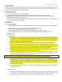
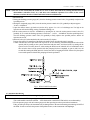
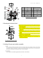
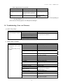
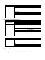
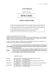
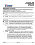
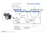
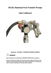
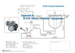
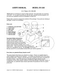
Document Number: S2MMB194.DOC
User Manual
KARYU turbo mixer
KTM_ND Series
KTM15ND, KTM20ND, KTM25ND, KTM32ND, KTM40ND
Thank you for purchasing the KARYU turbo mixer. Please read the user manual completely
before using the KARYU turbo mixer and use the KARYU turbo mixer correctly and safely.
After reading the manual, please store in the place so that it is accessible easily.
Please ensure that the person using this can access this manual easily.
In order for you to use this KARYU turbo mixer safely,
The usage method and the points to take care are described in this user manual. Since it may result in unexpected
problems if used in a wrong manner, please read the manual carefully before installation, wiring, operation,
maintenance and inspection of the KARYU turbo mixer and then use correctly.
In order to prevent harm, injury or any damage to the user and the people in the vicinity in a precautionary way,
the safety instructions are classified into ranks like [Warning] and [Note].
Warning
Note
In case of wrong usage, it may result in the death or serious injury of the user or the persons
nearby. Hence, please understand the contents of this manual completely and please follow
the instructions exactly.
In case of wrong usage, it may result in the medium or slight wound to the user or the
persons nearby, or in the physical damage. Hence, please understand the contents of this
manual completely and please follow the instructions exactly.
NIKUNI Co.,Ltd.
Head office : 843-5 Kuji, Takatsu-ku, Kawasaki, Kanagawa, Japan, Postal code: 213-0032
TEL (044)-833-1121
FAX (044)-822-1115
Osaka Office : 10F, 1-7-10, Doshou-machi, Chuo-ku, Osaka-shi, Osaka, Japan, Postal code: 541-0045
TEL (06)6205-7001
FAX (06)6205-7031
Nagoya Office : 5F, Asai Bldg.4-15-3, Imaike, Chikusa-ku, Nagoya-Shi, Aichi, Japan, Postal code: 464-0850
TEL (052)741-7301
FAX (052)741-7303
Nagano Office : 102 Garden Square, 1920 Yoshikawanomizo, Matsumoto, Nagano, Japan Postal code: 399-0003
TEL (0263)85-1330
FAX (0263)85-1332
1
Document Number: S2MMB194.DOC
Table of Contents
1. Introduction ・・・・・・・・・・・・・・・・・・・・・・・・・・・・・・・・・・・・・・・・・・・・
3
2. Unpacking check ・・・・・・・・・・・・・・・・・・・・・・・・・・・・・・・・・・・・・・・・
3
3. Installation・・・・・・・・・・・・・・・・・・・・・・・・・・・・・・・・・・・・・・・・・・・・・・
3
3-1. Place of installation
3-2. Plumbing work
3-3. Electrical wiring
4.Operation ・・・・・・・・・・・・・・・・・・・・・・・・・・・・・・・・・・・・・・・・・・・・・・
4
4-1.Attention when starting
4-2.Operating procedure
4-3.Attention when driving
4-4.Stop
5.Maintenance ・・・・・・・・・・・・・・・・・・・・・・・・・・・・・・・・・・・・・・・・・・・・
7
5-1. General precautions
5-2. Inspection of the shaft seal
5-3. Precautions in the case of long-term stoppage
5-4. Precautions for Long-term Storage
6. Disassembly ・・・・・・・・・・・・・・・・・・・・・・・・・・・・・・・・・・・・・・・・・・・・・
8
7. Assembly ・・・・・・・・・・・・・・・・・・・・・・・・・・・・・・・・・・・・・・・・・・・・・・・
8
8. Mounting the Gas suction nozzle ・・・・・・・・・・・・・・・・・・・・・・・・・・・
9
9. Ordering of the spare parts and the consumables ・・・・・・・・・・・・・
9
10. Troubleshooting (Cause and Measure) ・・・・・・・・・・・・・・・・・・・・・・
10
11. Repair and Warranty ・・・・・・・・・・・・・・・・・・・・・・・・・・・・・・・・・・・・
11
2
Document Number: S2MMB194.DOC
1. Introduction
Thank you very much for using the KARYU turbo mixer (KTM). We have taken utmost care while manufacturing so that
you can use this KTM safely. However, if this is used in a wrong manner, it may result in unexpected accident. Please use the
KTM carefully and correctly by referring to this manual.
2. Unpacking check
Once you receive the KTM, please check the following.
1) Confirm whether the model number printed on the nameplate is the same as the one you had ordered for.
2) Confirm whether no damages have occurred during the transportation and whether nuts and bolts are not loosened.
3) Confirm that all accessories and spare parts exist.
If there is any problem, please contact the seller by explicitly mentioning the model number printed on the nameplate and
the manufacturing number (serial number).
3. Installation
3-1 Place of installation
1) Please install at the place with surrounding temperature within 40℃, humidity within 95% and altitude within 1,000
m.
2) Select a place with good air circulation and with less dust as much as possible.
3) Select the place where maintenance and inspection is possible.
4) Please use a fence or enclosure to ensure that non-related persons do not access the KTM.
5) Please install the KTM in a place near to the water source so that the length of the suction pipe is short.
3-2 Plumbing work
1) Suction piping
(1) Please restrict the curves of the suction pipe to the minimum and connect to the water tank keeping the distance at
the minimum. Also, for the KTM inlet, use a straight pipe whose length is more than 6 times of the inlet diameter.
However, if the above conditions cannot be met due to the restrictions at the place of installation, please
implement the piping by carefully considering NPSH.
(2) Please ensure that the diameter of the suction pipe is as large as possible. (At least same as the Inlet diameter)
(3) If the water level of the water tank is below the KTM, fix the foot valve at the bottom of the suction line. Also, fix
the suction pipe in such a way that, the end of the suction pipe is inserted at the depth of more than 4 times of the
inlet diameter from the water level, and more than 2 times the diameter from the bottom of the tank.
(4) Upgrade the suction pipe towards the KTM (1/100 or more) so that air lock is not created. Also, please fix the
coupling of the suction pipe with utmost care so that air does not enter it.
(5) Please note that if particles like threading cuts, welding slag, sand etc. are inside the pipe, then the same would
enter the KTM and this would reduce the life of the KTM considerably. We recommend you to fix
strainer(around 100 meshes). Please clean this strainer neatly.
NOTE: (6) The gate valve attached to the suction side must be fully opened when starting up the KTM.
(7) Please restrict the curves of the suction pipe to the minimum and connect to the water tank keeping the distance at
the minimum. In case of high water temperature or if suction head is high or in case of volatile liquid etc. at the
inlet, if the piping is done without considering NPSH, the KTM cannot lift the water properly or the KTM may
run unstably and the KTM may get damaged. In some cases, pushing may be necessary if water temperature is
high or the liquid is volatile etc.
(8) We recommend the fixing of the sluice valve to enable convenient disassembling and inspection in case of flowing
and pushing, at the inlet.
2) Discharge piping
(1) Implement the discharge piping so that the piping length from the discharge outlet is minimum. If you cannot
avoid creation of air locks, please fix air vent valves at such positions. However, the air vent valves cannot be
fixed at places with negative pressures such as in Suction pipe. In such case, the air would be sucked in.
3
Document Number: S2MMB194.DOC
NOTE: (2) In case of KTM, if the discharge pressure increases, then load of the motor also increases. Hence, if due to
some reason the discharge outlet is closed, the motor power increases beyond limit.If the motor is under
operation in such situation for a long time, the KTM temperature increases and this may lead to complete
burn out of the motor. To avoid this, please fix the relief valve in between the KTM and the sluice valve to
ensure that the discharge pressure does not exceed the specified limits. With this, the KTM can be operated
in safe manner.
(3) If there is danger of the occurrence of the water hammer, you are needed to use the check valve to close rapidly or
other measures to avoid it.
NOTE 3) Other instructions for piping, plumbing
1) Support the piping enough in order to ensure that there is no unnecessary load on the KTM suction inlet
and discharge outlet. If piping is done when the position of the KTM suction inlet and the discharge
outlet does no match with the position of the pipe, there will be high force on the KTM and this may
result in the breakage of the suction inlet or discharge outlet and this results in reduced life of the KTM.
2) Implement the discharge piping in such a way that it is an erect piping at least 700 mm away from the
discharge outlet. Othewise the self-primed air does not get discharged, leading the long duration for the
discharge of water and hence water does not get pumped.
3-3 Electrical wiring
WARNING Please go through the Electrical equipments technical standards and extension regulations and the follow
them perfectly during the installation of Electric power equipments for the Motor and during the wiring. Please
avoid the incomplete wiring work, earthing done by unqualified personnel since it is not only illegal but also very
dangerous. Also, in order to prevent electric shock accidents, the law forces the use of electric leakage breaker.
Further, please install the Motor protection device in order to prevent the burn out due to motor overload etc.
4. Operation
4-1 Attention when starting
WARNING
1) Please confirm that the vicinity of the body of rotation is not dangerous when it drives.
2) If the electric power switch and the KTM are far from each other, then please do this work with the help of
1 or more persons and confirm that the region around the body of rotation is not dangerous.
NOTE
3) Confirm that there is no problem with rotation direction and the operation (no vibration and no noise) by
switching ON/Off of the switch 1-2 times(inching). If everything is fine, then proceed for the continuous
operation. If the rotation is in the opposite direction, do the wire connection so that the rotation direction is
corrected..
4) Please check whether there is no water leakage, air entry at each plug, cock, packing material, pipe
connection joints etc.
4-2 Operating Procedure
1) Rotate the KTM by hand to check if it rotates lightly. If it does not move smoothly, the vanes may be interfered.
2) Be sure to prime the KTM to fill the pump with water. If operated without priming, the KTM will go out of order.
Fully open the suction pressure control valve (V1) and discharge pressure control valve (V2). (They should never be
fully closed.)
Fully close the airflow control knob of the airflow meter (Q).
4
Document Number: S2MMB194.DOC
NOTE : 3) Be sure to turn on/off (inch) the switch once or twice to check the KTM for its rotating direction and any
abnormalities (vibrations, noise, etc.), and then, start continuous operation. If it rotates in the reverse
direction, reconnect the wires so that it will rotate in the forward direction.
4) Start the KTM.
5) Seeing the discharge pressure gauge (PG), close the discharge pressure control valve (V2) gradually to adjust to the
specified pressure.
6) Seeing the compound gauge (CPG), close the suction pressure control valve (V1) gradually to adjust to approx.
–0.04 to –0.05MPa-G.
7) Open the airflow meter’s (Q) knob to inject the air by approx. 5 to 10 % of a discharge rate. Too high an air
injection rate will result in idling, causing a mechanical leakage, etc.
8) If the suction pressure is raised to –0.02MPa-G by injecting the air, close the suction pressure control valve (V1)
gradually. If, as a result, the discharge pressure is lowered to -0.02 to -0.03MPa-G from the specified pressure,
close the discharge pressure control valve (V2) gradually to finely adjust to the specified pressure, and the air
injection rate as well.
9) Solenoid valve ((SV) when attached to the suction nozzle (N)): Option
Purpose: Prevention of counterflow of the fluid to the airflow meter (Q) when the pump is stopping.
Control: This has been set to Open at the time of power-on. In case of forcing, ensure that the solenoid valve will be
opened (ON) by turning on the system, interlocked with the motor, and closed (OFF) by turning off the
system. In case of suction, however, when starting the KTM, use the solenoid valve in combination with a
flow switch so that it will be opened (ON) after pumping has been completed, or open it (ON) 30 to 60
seconds after starting the KTM and close it at the same time of stopping the KTM. If the air is injected prior
to successful operation of the KTM, pumping will not be performed.
Fig-2 KTM : KARYU turbo mixer
4-3 Attention when driving
WARNING 1) Please do not touch the rotating body to prevent the danger.
2) Check whether the KTM is operating smoothly without vibration and noise.
(The small metallic sound such as Kiiinn… is the characteristic sound of the KTM and it is not an abnormality.)
3) Use the pressure gauge cock and vacuum gauge cock after squeezing in order to protect these instruments.
If they are left open always, the instruments may be damaged due to the water hammering action during ON/OFF of
the KTM. In order to measure the pressure of the polluted water, use the instruments with diaphragm.
5
Document Number: S2MMB194.DOC
4) Please pay attention to the pressure, KTM discharge volume, power value, operating sound.
If foreign bodies get clogged up in the Foot valve, Strainer, impeller etc., these values changes suddenly (vibration
of the pressure gauge needle, the vibration of the Vacuum Gauge needle, reduction in water level, change in electric
current value, abnormal sound) and this enables you to detect the problem at an early stage and also allows you to
rectify the problem at an early stage and hence serves as the measure to prevent big accidents
5) Please confirm whether the actual measured values in 4) meets the discharge volume, head, power value being used.
(The pressure gauge displays the value multiplying the head and the specific gravity. Also, if the specific gravity , viscosity
of the water is high, the electric current value increases.)
NOTE 6) In order to protect the mechanical seal, use with the discharge head (head) of at least 10 m. If the head is less
than 10 m, please contact the dealer or our company. Please avoid the idle run of the KTM.
7) Once the lifetime of the mechanical seal is over, the leakage increases very rapidly. It is strongly recommended to
have a spare with you. Please ensure that you run the spare KTM once in a while, in order to ensure that it is in the
working condition.
8) If the KTM is operated continuously, the temperature of the shaft bearing increases. However, if it can be touched
by hand, then there is no concern.
(The tolerable increase in temperature of the shaft bearing on the surface of the bracket is within surrounding
temperature + 40 ℃ and the maximum temperature is within 75 ℃)
NOTE 9) Do not loosen the plugs, bolts or nuts during the operation. This may result in scattering of the liquid inside
the KTM or dislocation of the parts, which is dangerous.
4-4 Stop
Open the discharge adjustment valve completely and switch OFF. If there is a electric power failure during the
operation, please switch OFF the power immediately and open the discharge adjustment valve completely.
NOTE
Irrespective of the long term stoppage and short-term stoppage, drain out the water completely without fail.
6
Document Number: S2MMB194.DOC
5.Maintenance
5-1 General Precautions
NOTE 1) Before inspecting the KTM, please cutoff the main power without fail. This is to avoid dangers like sudden
start of the KTM due to Automatic operation etc.
2) Do not allow persons other than repair technicians to disassemble, repair, renovate etc. This may result in
fire ignition, abnormal operations which would be dangerous.
3) Check whether the KTM is operating smoothly without vibrations.
4) Check the water level in the tank and the pressure at the suction inlet.
5) Compare the discharge pressure, power value during the operation with the values printed on the nameplates on the
KTM, motor and check the operating load of the KTM.
6) Please note the pressure gauge displays the value, which is the sum of the head and the specific gravity.
7) Open the cock of the pressure gauge, vacuum gauge during the measurement, and close after the measurement.
If it were left open always, then the instruments would be damaged due to the abnormal pressure of the water hammer
etc. For the measurement of the pressure of the polluted water, measure via U-tube with water (if the pressure is below
0.1 MPa [gauge]) or measure using the instrument with diaphragm.
8) Make notes of the standard control values of the gas injection rate and the compound gauge and pressure gauge
indication values to check them periodically.
5-2 Inspection of the shaft seal
Mechanical Seal
NOTE 1)After implementing the priming completely, start the operation. Please avoid the idle operation.
2) Confirm that there is no abnormal noise, vibration, and heat generation during the operation.
3) Since the mechanism of the mechanical seal is in such a way that, the tight sealing is achieved by liquid membrane
is created on the sliding surfaces due the lubrication of the liquid used, even though there is no leakage visible, there
would be a minute leakage of the liquid. Due to this mechanism, the leakage of the liquid may occur due to the
nature of the liquid, pressure, operation method etc. If you face liquid leakage problem, you have to either install the
drain piping/ drain pan or replace the mechanical seal upon consulting the dealer or our company. (Please refer to
Section 8-2 Consumables for the replacement)
5-3 Precautions in the case of long-term stoppage
1) There is a danger of damage to the KTM not only in the case of long-term stoppage of operation, but also due to the
freezing of the liquid during winter even if operation is stopped for a short duration. Please completely drain out the
liquid of KTM inside.
2) Please follow 4) Operation, when resuming the operation.
5-4 Precautions for Long-term Storage
1) Please implement 2) Unpacking check without fail.
2) Please ensure that foreign bodies do not enter into suction inlet and the discharge outlet.
7
Document Number: S2MMB194.DOC
6. Disassembly (Refer Fig-2 KTM_ND Cross section diagram)
NOTE Shut off the POWER before disassembling/ assembling the KTM. This is to avoid dangers like sudden
start of the KTM due to Automatic operation etc.
1) Remove the bolt used to fix the cover [103] to the body [102] and detach the cover [103] and the O-ring [123].
Loosen the hexagon socket setscrew [164] holding the impeller [107] and detach the impeller [107].
Note : If it is difficult to detach the impeller, then screw in the bolt into the Tap hole of the impeller and then
remove the impeller by pulling this bolt.
2) Detach the key [116] attached to the shaft [108] of the motor and detach the rotating part of the mechanical seal
[051].
3) Remove the bolt holding the motor and the body [102] and detach the body [102].
4) Detach the low head cap [151C] from the body [102] and detach the mechanical seal holder [049] and the fixed part
of the mechanical seal [051].
5) Detach the slinger [081] attached to the shaft [108] of the motor.
This completes the disassembly process.
7. Assembly
It is fine if you can assemble in the reverse order of the disassembly. However, please assemble each part perfectly using
the following procedure.
1) Insert the slinger [081] into the shaft [108] of the motor up to the shaft level.
2) Attach the fixed part of the mechanical seal [051] to the body [102], tighten the mechanical holder [049] uniformly
using the low head cap [151C] and fix it.
3) Insert the assembled set of parts of the body in Step 2 into the motor shaft, tighten uniformly using the bolts and
attach to the motor flange.
4) Insert the rotating part of the mechanical seal [051] till it touches the fixed part. Please ensure that there are no
foreign bodies attached to the sliding surface of the mechanical seal, by wiping using alcohol etc.
5) Insert the key [116] into the key groove of the motor shaft [108], and assemble the impeller [107]. During this time,
please ensure that the pin of the rotating part of the mechanical seal [051] is inside the hole of the impeller [107].
6) Fix the impeller [107] using the hexagon socket setscrew [164]. During this, adjust the position of the impeller [107]
so that it does not touch the body [102] and the cover [103].
7) Fit the O-ring [123] into the cover [103], fix this uniformly using the bolt and fix to the body [102].
This completes the assembly.
Further, please take care about the following points.
NOTE : Confirm that the motor fan turns smoothly by turning it by hand. If the rotation is abnormal or if it does not
rotate properly, there is a problem in the parts or the assembly. Please re-inspect the same.
8
Document Number: S2MMB194.DOC
103
Cover
164
Hexagon socket setscrew
102
Body
151C
Low head cap
081
slinger
123
O-ring
051
Mechanical Seal
116
Key
049
Mechanical seal holder
108
Shaft
032
Collar
107
Impeller
No.
Name
No.
Name
Fig-2 KTM_ND Cross section diagram
8. Mounting the Gas Suction Nozzle
1) Loosen the nuts of the lower pipe joint to allow a nipple to freely move.
2) Mark the pipe bending direction on the pipe surface between the upper
and lower pipe joints.
3) Wind a sealing tape around the lower pipe joint’s nipple of the suction
nozzle, insert it into the nozzle junction of the pump, and turn the nipple
to firmly fix it.
4) Turn the pipe to align the mark on the pipe surface so that the bend
nose (gas discharge port) of the pipe will be directed to the center of the
impeller.
5) Tighten the nuts of the lower pipe joint firmly. Make sure that the
suction nozzle is not manually rotated.
6) Rotate the motor manually (rotate the shaft end of the motor with a
screwdriver) to make sure that the pipe nose of the nozzle is not
interfering with the impeller.
Fig-3 Mounting the Gas Suction Nozzle
9. Ordering of the spare parts and the consumables
1) Order
Please mention the KTM model number and the serial number printed on the nameplate correctly, when ordering
the spare parts and the consumables. Also, please specify the Part number and the Part name of the required spare
parts and the consumables by referring to the Fig-3 Cross Section diagram.
2) Consumables
Please replace the consumables regularly based on the Table-1 as the indication.
9
Document Number: S2MMB194.DOC
Table-1 Replacement of consumables
Consumable parts
Symptom of consumption
Mechanical seal
Increase in liquid leakage
Bearings
Noise becomes severe.
Abnormal sound is generated
(Note 2)
O-ring
-
Replacement time
Once in a year (Note 1)
Once in 2-3 years
During disassembly
inspection
(Note 1) The average replacement frequency of the mechanical seal is 1-2 years. However, it varies depending on
the usage. (Refer 5-2.3)
(Note 2) In case of such symptom, even other parts are damaged.
10. Troubleshooting (Cause and Measure)
1) Trouble during Startup
Symptom
. Motor does not rotate
. Motor growls and does not rotate
.
.
.
.
.
.
Cause
Electrical power related problem
Motor breakdown
Rotating parts touch something else
Rotating part is rusted
Rotating part is in seizure
Foreign body clogged in the rotating part
Countermeasure
Inspect and repair
Disassemble, inspect and then repair
Get it repaired by the manufacturer
Cause
Water priming is not done
Sluice valve is closed and partially open
Actual head is more than the KTM head
Suction lift is too much for this KTM
Air vent valve is closed
Suction pipe end is not submerged in the
water
Direction of rotation is reverse
Countermeasure
Do water priming
Open the valve completely
Reduce the actual head
Reduce the suction lift
Open the air vent valve
Immerse the suction pipe end into the water
2) Trouble related to Pumping
Symptom
Cannot pump the water
Specified discharge volume, specified
head not met
Water is pumped initially, but stops
immediately
Operating under 50Hz instead of 60Hz
Number of poles in the motor is different
Voltage drop
Strainer or the foot valve is blocked
Pipe is blocked
Air is being sucked
Leakage in the discharge pipe
Horizontal pipe is very long
Impeller is corroded
Impeller is worn out
Correct the wiring, and confirm the direction using the
arrow mark on the KTM
Adjust to the specified rotation speed
Change the motor
Supply the correct voltage
Remove the foreign bodies
Remove the foreign bodies
Inspect the suction pipe, shaft seal part and repair accor
dingly
Inspect and repair
Reduce the length
Replace the impeller
Get it repaired by the manufacturer
Check the body also
Improve the suction piping
Reduce
Cavitations has occurred
Too much pressure loss in piping
Air is accumulated (locked) inside the dischar
Provide air vent
ge pipe
Close the gland packing
Entrained air from the Gland packing part
Inject water into the gland
10
Document Number: S2MMB194.DOC
3) Overload problems
Symptom
Overload
Cause
Operating under 50Hz instead of 60Hz
Number of poles in the motor is different
Voltage drop
Foreign bodies have entered into the internal
portion of the KTM
Head is very high and discharge flow
volume is very less
Shaft bearing is damaged
Rotating parts are touching other things
The shaft is bent
The strainer is blocked
Countermeasure
Adjust to the specified rotation speed
Change the motor
Supply the correct voltage
Remove the foreign bodies
Open the discharge valve
Get it repaired by the manufacturer
Get it repaired by the manufacturer
Replace the motor
Replace the motor and KTM
Inspect the strainer and clean it
4) Problems related to Shaft bearing, Shaft seal and others
Symptom
Cause
Overheat or abnormal noise is gen Centering is not correct
erated in the Shaft bearing
Shaft bearing is damaged
Shutoff operation for long duration
Overleakage of water from the
Wrong fixture of mechanical seal
shaft seal portion
Mechanical seal is damaged
Shaft is worn out
Shaft is bent
Shaft bearing is damaged
Direction of rotation is reverse
Rotating parts are touching other things
The shaft is bent
Cavitations has occurred
Piping is resonating
Countermeasure
Redo the centering and adjust correctly
Replace the shaft bearing
Stop the shutoff operation
Fix correctly
Replace the mechanical seal
Replace the motor
Replace the motor and KTM
Get it repaired by the manufacturer
Correct the wiring, and confirm the direction using the
arrow mark on the KTM
Get it repaired by the manufacturer
Replace the motor
Replace the motor and KTM
Improve the suction piping
Improve the piping
Install flexible pipe, vibration isolating rubber cushion
5) Causes for unstable microbubbles
Symptom
Unstable gas-liquid mixing
Cause
Descending pipe or arch piping after releasing
the discharge pressure
Inappropriate air injection rate
Inappropriate suction/discharge pressure
Clogged piping after releasing the discharge
pressure
Unstable air suction
Mixed large bubbles
*1: To generate more stable microbubbles, use a microbubble generator (MBG).
Countermeasure
Improve the piping
Adjust the air injection rate appropriately
Adjust the suction/discharge pressure
Eliminate foreign substances
Insufficient negative load
Install a separation tank (option). *1
11. Repair and Warranty
In case of repair or maintenance of the product, please contact the seller or our company. We are at your service. For this
product, we guarantee our product as per the WARRANTY LETTER FORM as attached.
11
Document Number: S2MMB194.DOC
THE WARRANTY LETTER FORM
Dear Sirs,
WARRANTY OF QUALITY
We hereby guarantee the quality of our product supplied to you in the following conditions:
1)
2)
3)
4)
5)
Nikuni warrants our product to be free of defects in material and workmanship for a period of one (1) year of our shipment
from our factory in Japan, or our factory in China. Any parts which fails during the warranty period due to defective
material or workmanship will be replaced without charge, Ex-Go Nikuni factory, provided (a)the claim for warranty is
given in writing describing details of the defect within warranty period; (b)Nikuni accept to return of defective part(s) for
service: and (c)the defective part(s) is delivered to Nikuni, transportation charge prepaid, in accordance with instruction of
Nikuni. In case of difference of opinion of the parties concerned regarding the warranty is applicable or not, the judgement
of Nikuni is final.
Nikuni’s liability is limited to the replacement or repair (at our option) of the defective parts as originally supplied by us. We
shall not be liable for any loss, damage, or expenses directly or indirectly related to the use of its products or from any other
cause or for consequential damages (including, without limitation, loss of time, inconvenience, and loss of production). It is
expressly understood that Nikuni is not responsible for damage or injury caused to other products, machinery, buildings,
property, or persons by reason of the installation or use of its products.
The warranty shall be null and void if any component of a product has been (a) tampered with, disassembled, repaired or
altered (except as may be authorized by Nikuni in writing); (b) subject to misuse, neglect or accident; or (c) used to
materials which it was not designed to handle, which may attack or harm the materials used in construction of the product,
or which may otherwise harm the operation of the product.
The warranty does not cover or apply to (a) the effects of corrosion, abrasion or normal wear; (b) repairs or service
adjustments required due to lack of proper maintenance, natural causes or acts of God; or (c) any field expense for service or
replacement of parts.
This warranty is Nikuni’s sole warranty and in lieu of all other warranties, express or implied , which are hereby disclaimed,
including in particular all warranties of merchantability or fitness for a particular purpose.
Yours faithfully,
Nikuni Co.,Ltd.
12