1
5. PARAMETERS
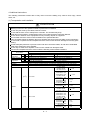
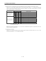
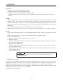
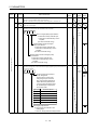
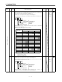
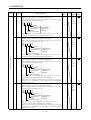
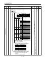
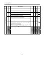
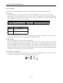
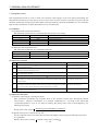
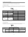
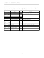
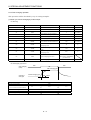
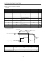
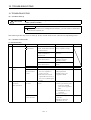
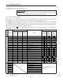
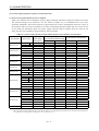
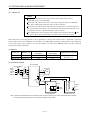
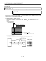
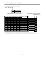
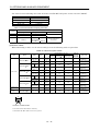
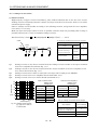
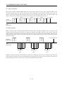
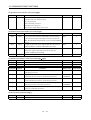
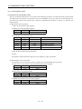
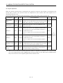
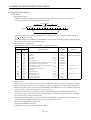
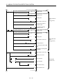
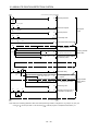
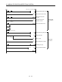
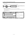
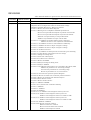
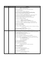
(2) Set content
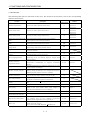
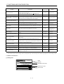
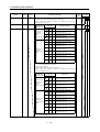
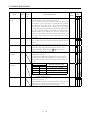
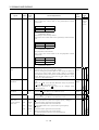
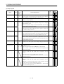
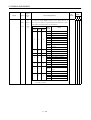
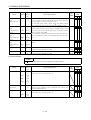
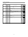
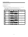
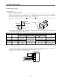
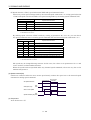
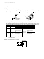
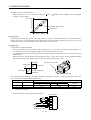
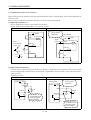
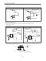
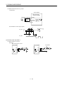
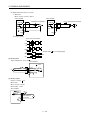
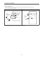
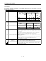
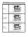
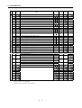
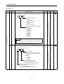
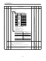
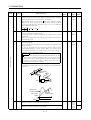
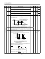
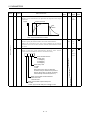
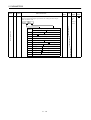
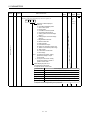
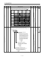
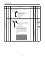
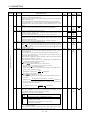
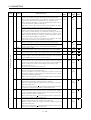
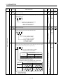
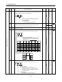
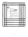
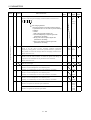
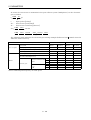
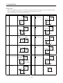
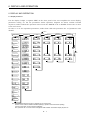
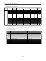
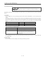
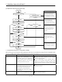
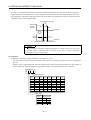
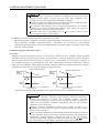
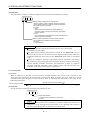
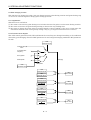
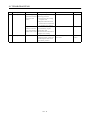
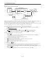
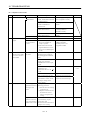
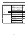
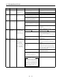
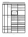
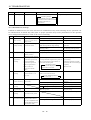
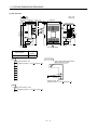
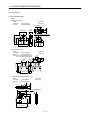
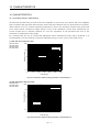
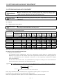
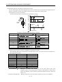
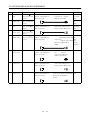
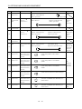
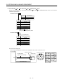
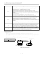
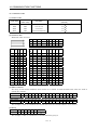
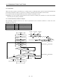
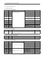
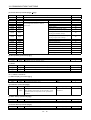
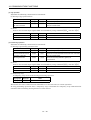
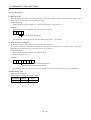
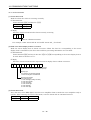
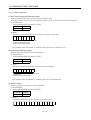
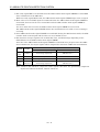
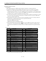
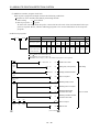
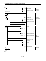
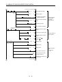
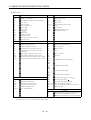
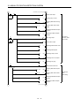
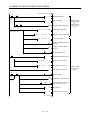
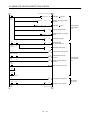
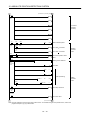
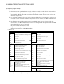
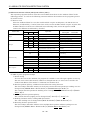
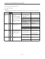
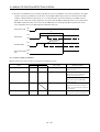
The servo amplifier is factory-set to output the motor speed to ch1 and the torque to ch2. The setting
can be changed as listed below by changing the parameter No.17 value:
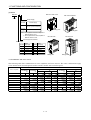
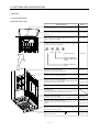
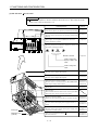
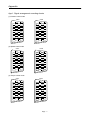
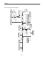
Refer to Appendix 2 for the measurement point.
Setting
0
Output item
Motor speed
Description
Setting
6
CCW direction
8[V]
Output item
Droop pulses
( 10V/128pulse)
Description
10[V]
CCW direction
128[pulse]
Max. speed
0
0 Max. speed
8[V]
1
Torque
8[V]
Driving in CCW direction
7
Droop pulses
( 10V/2048pulse)
10[V]
0 2048[pulse]
0 Max. torque
2
CCW direction
2048[pulse]
Max. torque
Driving in CW direction
10[V]
CW direction
CW direction
128[pulse]
8[V]
Motor speed
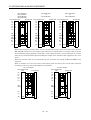
8
CW
direction 8[V]
10[V]
CW direction
CCW
direction
Droop pulses
( 10V/8192pulse)
10[V]
CCW direction
8192[pulse]
0 8192[pulse]
Max. speed
0 Max. speed
10[V]
CW direction
3
Torque
9
Driving in
CW direction 8[V]
Driving in
CCW direction
Droop pulses
( 10V/32768pulse)
10[V]
CCW direction
32768[pulse]
0 32768[pulse]
Max. torque
0 Max. torque
10[V]
CW direction
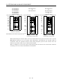
4
5
Current command
(Torque command)
Command pulse
frequency
8[V] CCW direction
Max. command
current
(Max. torque
command)
0 Max. command
current
(Max. torque
command)
8[V]
CW direction
A
10[V]
CCW direction
131072[pulse]
0
CW direction
B
CCW direction
10[V]
Droop pulses
( 10V/131072pulse)
131072[pulse]
10[V]
Bus voltage
8[V]
500kpps
0
500kpps
0
10[V]
CW direction
5 - 30
400[V]