1
User’s Manual Model DO402G [Style: S3] Dissolved Oxygen Converter IM 12J05D02-01E IM 12J05D02-01E 8th Edition PREFACE WARNING Electric discharge The EXA analyzer contains devices that can be damaged by electrostatic discharge. When servicing this equipment, please observe proper procedures to prevent such damage. Replacement components should be shipped in conductive packaging. Repair work should be done at grounded workstations using grounded soldering irons and wrist straps to avoid electrostatic discharge. Installation and wiring The EXA analyzer should only be used with equipment that meets the relevant IEC, American or Canadian standards. Yokogawa accepts no responsibility for the misuse of this unit. CAUTION The Instrument is packed carefully with shock absorbing materials, nevertheless, the instrument may be damaged or broken if subjected to strong shock, such as if the instrument is dropped. Handle with care. Although the instrument has a weatherproof construction, the transmitter can be harmed if it becomes submerged in water or becomes excessively wet. Do not use an abrasive or solvent in cleaning the instrument. Notice • This manual should be passed on to the end user. • The contents of this manual are subject to change without prior notice. • The contents of this manual shall not be reproduced or copied, in part or in whole, without permission. • This manual explains the functions contained in this product, but does not warrant that they are suitable the particular purpose of the user. • Every effort has been made to ensure accuracy in the preparation of this manual. However, when you realize mistaken expressions or omissions, please contact the nearest Yokogawa Electric representative or sales office. • This manual does not cover the special specifications. This manual may be left unchanged on any change of specification, construction or parts when the change does not affect the functions or performance of the product. • If the product is not used in a manner specified in this manual, the safety of this product may be impaired. Yokogawa is not responsible for damage to the instrument, poor performance of the instrument or losses resulting from such, if the problems are caused by: • Improper operation by the user. • Use of the instrument in improper applications • Use of the instrument in an improper environment or improper utility program • Repair or modification of the related instrument by an engineer not authorized by Yokogawa. Safety and Modification Precautions • Follow the safety precautions in this manual when using the product to ensure protection and safety of the human body, the product and the system containing the product. The following safety symbols are used on the product as well as in this manual. DANGER DANGER This symbol indicates that an operator must follow the instructions laid out in this manual in order to avoid the risks, for the human body, of injury, electric shock, or fatalities. The manual describes what special care the operator must take to avoid such risks. IM 12J05D02-01E WARNING This symbol indicates that the operator must refer to the instructions in this manual in order to prevent the instrument (hardware) or software from being damaged, or a system failure from occurring. CAUTION This symbol gives information essential for understanding the operations and functions. This symbol indicates Protective Ground Terminal This symbol indicates Function Ground Terminal (Do not use this terminal as the protective ground terminal.) This symbol indicates Alternating current. This symbol indicates Direct current. Warranty and service Yokogawa products and parts are guaranteed free from defects in workmanship and material under normal use and service for a period of (typically) 12 months from the date of shipment from the manufacturer. Individual sales organizations can deviate from the typical warranty period, and the conditions of sale relating to the original purchase order should be consulted. Damage caused by wear and tear, inadequate maintenance, corrosion, or by the effects of chemical processes are excluded from this warranty coverage. In the event of warranty claim, the defective goods should be sent (freight paid) to the service department of the relevant sales organization for repair or replacement (at Yokogawa discretion). The following information must be included in the letter accompanying the returned goods: • Part number, model code and serial number • Original purchase order and date • Length of time in service and a description of the process • Description of the fault, and the circumstances of failure • Process/environmental conditions that may be related to the installation failure of the device • A statement whether warranty or non-warranty service is requested •Complete shipping and billing instructions for return of material, plus the name and phone number of a contact person who can be reached for further information. Returned goods that have been in contact with process fluids must be decontaminated/disinfected before shipment. Goods should carry a certificate to this effect, for the health and safety of our employees. Material safety data sheets should also be included for all components of the processes to which the equipment has been exposed. How to dispose the batteries: This is an explanation about the new EU Battery Directive (DIRECTIVE 2006/66/EC). This directive is only valid in the EU. Batteries are included in this product. Batteries incorporated into this product cannot be removed by yourself. Dispose them together with this product. When you dispose this product in the EU, contact your local Yokogawa Europe B.V.office. Do not dispose them as domestic household waste. Battery type: silver oxide battery Notice: The symbol (see above) means they shall be sorted out and collected as ordained in ANNEX II in DIRECTIVE 2006/66/EC. IM 12J05D02-01E TABLE OF CONTENTS PREFACE.....................................................................................................................1 1. Introduction And General Description.............................................................. 1-1 1-1. Instrument Check............................................................................................. 1-1 1-2. Application....................................................................................................... 1-2 1-3. General information......................................................................................... 1-3 1-4. Configuration checklist for DO402................................................................... 1-5 1-5. System Configuration...................................................................................... 1-6 1-5-1. Dissolved Oxygen Sensor................................................................................................1-6 1-5-2. The holders.......................................................................................................................1-7 2. DO402G SPECIFICATIONS................................................................................. 2-1 2-1. General............................................................................................................ 2-1 2-2. Operating specifications.................................................................................. 2-2 2-3. Model and suffix codes.................................................................................... 2-3 3. Installation And Wiring....................................................................................... 3-1 3-1. Installation and dimensions............................................................................. 3-1 3-1-1. Installation site..................................................................................................................3-1 3-1-2. Mounting methods............................................................................................................3-1 3-2. Wiring............................................................................................................... 3-3 3-2-1. Wiring of DO30G..............................................................................................................3-3 3-2-2. Wiring of DO70G..............................................................................................................3-3 3-2-3. Preparation................................................................................................... 3-4 3-3. Wiring the power supply.................................................................................. 3-5 3-3-1. 3-3-2. 3-3-3. 3-3-4. 3-3-5. General precautions.........................................................................................................3-5 Access to terminal and cable entry..................................................................................3-6 AC power..........................................................................................................................3-7 Grounding the housing.....................................................................................................3-7 Switching on the instrument.............................................................................................3-7 3-4. Wiring the contact signals................................................................................ 3-8 3-4-1. General precautions.........................................................................................................3-8 3-4-2. Contact outputs................................................................................................................3-8 3-4-3. Contact input....................................................................................................................3-8 3-5. Wiring the analog output signals...................................................................... 3-9 3-5-1. General precautions.........................................................................................................3-9 3-5-2. Analog output signals.......................................................................................................3-9 3-6. Wiring the standard galvanic sensor............................................................... 3-9 3-7. Wiring other galvanic sensors........................................................................ 3-10 3-8. Wiring the standard optical sensor (DO70G)................................................. 3-10 3-9. Wiring polarographic sensors.........................................................................3-11 3-10. Wiring RS485 signal.....................................................................................3-11 4. Operation; Display Functions And Setting....................................................... 4-1 4-1. Operator interface............................................................................................ 4-1 4-2. Explanation of operating keys.......................................................................... 4-2 4-3. Setting passcodes........................................................................................... 4-3 4-4. Display functions (default)............................................................................... 4-4 5. Parameter setting................................................................................................ 5-1 5-1. Maintenance mode.......................................................................................... 5-1 5-1-1. Manual activation of Hold.................................................................................................5-2 IM 12J05D02-01E 8th Edition: Feb. 2014(YK) All Rights Reserved, Copyright © 2003, Yokogawa Electric Corporation IM 12J05D02-01E 5-1-2. Manual Wash start/stop....................................................................................................5-3 5-1-3. Setpoint adjustment..........................................................................................................5-4 5-2. Commissioning mode...................................................................................... 5-5 5-2-1. 5-2-2. 5-2-3. 5-2-4. 5-2-5. Setpoints...........................................................................................................................5-6 Range...............................................................................................................................5-8 Hold ...............................................................................................................................5-10 Wash .............................................................................................................................5-12 Service............................................................................................................................5-13 5-3-1. 5-3-2. 5-3-3. 5-3-4. 5-3-5. 5-3-6. 5-3-7. 5-3-8. 5-3-9. Parameter specific functions..........................................................................................5-14 Temperature functions....................................................................................................5-16 Calibration functions.......................................................................................................5-16 mA output settings..........................................................................................................5-18 Contact outputs..............................................................................................................5-20 User interface.................................................................................................................5-26 Communication setup.....................................................................................................5-28 General ..........................................................................................................................5-28 Test and setup mode .....................................................................................................5-28 5-3. Notes for guidance in the use of service coded settings............................... 5-14 6. CALIBRATION PROCEDURE.............................................................................. 6-1 6-1. General............................................................................................................ 6-1 6-1-1. Calibration methods..........................................................................................................6-1 6-1-2. Diagnostic functions performed during calibration...........................................................6-2 6-2. Calibration procedure using air calibration method......................................... 6-2 6-2-1. Preparation.......................................................................................................................6-2 6-2-2. Procedure for air calibration.............................................................................................6-3 6-3. Calibration procedure using water calibration method..................................... 6-4 6-3-1. Preparation.......................................................................................................................6-4 6-3-2. Calibration operation (water calibration method)..............................................................6-4 6-3-3. Procedure for Water calibration........................................................................................6-5 6-4. Calibration method using manual calibration method...................................... 6-6 6-4-1. Preparation.......................................................................................................................6-6 6-4-2. Procedure for manual calibration.....................................................................................6-7 7. Maintenance......................................................................................................... 7-1 7-1. Overall dissolved oxygen metering system..................................................... 7-1 7-1-1. Inspection and maintenance to be implemented periodically...........................................7-1 7-1-2. Inspection and maintenance to be implemented on occasion.........................................7-1 7-2. Periodic maintenance for the EXA DO402G converter.................................... 7-2 7-3. Fuse Replacement........................................................................................... 7-2 8. Troubleshooting.................................................................................................. 8-1 8-1. Measures in the case of converter operation failure........................................ 8-1 8-1-1. No dissolved-oxygen converter operation........................................................................8-1 8-1-2. Operation key or display failure........................................................................................8-1 8-2. Measures in the case of failure (Error) detection............................................. 8-2 9. Spare Parts.......................................................................................................... 9-1 10. Appendix ......................................................................................................... 10-1 10-1. Setpoint........................................................................................................ 10-1 10-2. Range.......................................................................................................... 10-1 10-3. Hold............................................................................................................. 10-1 10-4. Wash............................................................................................................ 10-1 10-5. User setting table......................................................................................... 10-2 IM 12J05D02-01E 11. Appendix 2 QUALITY INSPECTION.................................................................11-1 Customer Maintenance Parts List (for Style: S3) ..................CMPL 12J05D02-03E Revision Record ..........................................................................................................i IM 12J05D02-01E Introduction 1-1 1. Introduction And General Description The Yokogawa EXA is a 4-wire coverter designed for industrial process monitoring, measurement and control applications. This instruction manual contains the information needed to install, set up, operate and maintain the unit correctly. This manual also includes a basic troubleshooting guide to answer typical user questions. Yokogawa can not be responsible for the performance of the EXA analyzer if these instructions are not followed. 1-1. Instrument Check Upon delivery, unpack the instrument carefully and inspect it to ensure that it was not damaged during shipment. If damage is found, retain the original packing materials (including the outer box) and then immediately notify the carrier and the relevant Yokogawa sales office. Make sure the model number on the textplate affixed to the top of the display board of the instrument agrees with your order. WARNING The textplate will also contain the serial number and power supply selection. Be sure to apply correct power to the unit. MODEL DO402G SUFFIX STYLE SUPPLY OUTPUT No. 115VAC 50/60Hz MAX.10VA 0-20mADC or 4-20mADC Made in Japan Figure 1-1. Nameplate example Check that all the parts are present, including mounting bracket, as specified in the option codes at the end of the model number. For a description of the model codes, refer to Chapter 2 of this manual under General Specifications. Basic Parts List: Converter EXA 402 User’s Manual (See model code for language) Optional mounting bracket when specified (See model code) IM 12J05D02-01E 1-2 Introduction 1-2. Application The EXA converter is intended to be used for continuous on-line measurement in industrial installations. The unit combines simple operation and microprocessor-based performance with advanced self-diagnostics and enhanced communications capability to meet the most advanced requirements. The measurement can be used as part of an automated process control system. It can also be used to indicate dangerous limits of a process, to monitor product quality, or to function as a simple controller for a dosing/neutralization system. Yokogawa designed the EXA analyzer to withstand harsh environments. The converter may be installed either indoors or outside because the IP65 (NEMA 4X) housing and cabling glands ensure the unit is adequately protected. The flexible polycarbonate window on the front door of the EXA allows pushbutton access to the keypad, thus preserving the water and dust protection of the unit even during routine maintenance operations. A variety of EXA hardware is optionally available to allow wall, pipe, or panel mounting. Selecting a proper installation site will permit ease of operation. Sensors should normally be mounted close to the converter in order to ensure easy calibration and peak performance. If the unit must be mounted remotely from the sensors, WF10 extension cable can be used up to a maximum of 50 metres (150 feet) with a BA10 junction box. The EXA is delivered with a general purpose default setting for programmable items. (Default settings are listed in Chapter 5 and again in Chapter 10). While this initial configuration allows easy start-up, the configuration should be adjusted to suit each particular application. An example of an adjustable item is the type of temperature sensor used. The EXA can be adjusted for any one of four different types of temperature sensors. To record such configuration adjustments, write changes in the space provided in Chapter 10 of this manual. Because the EXA is suitable for use as a monitor, a controller or an alarm instrument, program configuration possibilities are numerous. Details provided in this user’s manual are sufficient to operate the EXA with all Yokogawa sensor systems and a wide range of third-party commercially available probes. For best results, read this manual in conjunction with the corresponding sensor user’s manual. IM 12J05D02-01E Introduction 1-3 1-3. General information Flexibility, reliability and low maintenance are among the benefits provided by the EXA DO402G dissolved oxygen analyzer. Designed to meet the exacting requirements of measuring dissolved oxygen in the modern industrial environment, it contains many features to ensure the best precision whatever the application. This 4-wire converter is housed in a robust IP65 field mountable case. Two mA outputs, four relays, digital communication and a clear LCD make the DO402G a truly comprehensive package. The DO402G features PI control on both the auxiliary mA output and the pulse proportional relay outputs, thus avoiding the need for a separate controller. The famous EXA sensor diagnostics are now expanded with a logbook facility in combination with the RS485 two wire communication software option. This can be used to record events like calibration and diagnostic messages, and to update configuration of the converter remotely. The DO402G accepts inputs from galvanic, polarographic and optical sensors. Percent saturation, mg oxygen/l water, and ppm DO can be displayed and transmitted. Compensation for atmospheric pressure altitude, salinity and temperature are included for the best accuracy of measurement. Features • Simple 3 Ievel operation • Display mg/l, ppm, % saturation • Air calibration or saturated water calibration • Chloride concentration compensation can be programmed • Automatic temperature compensation • Built-in barometric air pressure compensation • “Hold” function enables fixed output signal during maintenance • Two separate mA output signals • Wide flexibility incorporating free programmable range settings, selection of output signals and alarm functions • Analog output with adjustable damping time • Password protection for each programming level • Built-in wash timer with remote start possibility • IP65 weather protection • Universal mounting possibilities • Sensor diagnostics • RS 485 bi-directional communication • Logbook via RS 485 link • PI control on mA and pulsed contact controls Method of operation The EXA DO30 operates on a galvanic cell principle. The sensor contains a measuring cell consisting of a silver cathode and a lead anode. The voltage generated by this electrode pair is sufficient to generate a spontaneous reduction of oxygen at the cathode, so no external voltage source for this reaction is required. The electrodes are immersed in an electrolyte containing potassium hydroxide. Oxygen molecules can pass through a permeable membrane into the cell. The output current of the cell is directly related to the partial pressure of oxygen at the sample side. In the sensor a thermistor is integrated to be able to correct for temperature changes. Both signals are used in the converter to ensure an automatically compensated value for dissolved oxygen. Calibration is worked out by simple air calibration to make sure that the performance of the instrument will be maintained. The DO70G sensor operates based on the principle of optical (fluorescence) measurement. The sensor comprises a fluorescent membrane, light-emitting part, light-receiving part, and internal circuit. An external power source is required. Oxygen molecules pass through the permeable membrane to a fluorescent substance and shift the phase of fluorescent emission. The degree of this shift is inversely proportional to the partial pressure of oxygen on the sample side, resulting in the output of a current equivalent to the polarographic current adjusted by the internal circuit. A temperature sensor is integrated in both sensors, and the temperature signals are used to automatically compensate the measurements of dissolved oxygen. The combination of air-saturated water calibration and zero calibration helps maintain the performance of the instrument. IM 12J05D02-01E 1-4 Introduction Display functions and ranges The display continuously gives you all necessary information at a glance. The process values are shown in easily readable programmable units. Either mg/l. % saturation or ppm can be chosen. The user-interface is simplified to a basic set of 6 keys accessible through the flexible window cover. It uses a simple step by step, question and answer style to communicate with the operator by giving messages on the second line of the display and indicating which keys are to be pressed in the display. Automatic air calibration Calibration for a dissolved oxygen instrument is performed by simple air calibration (please refer to 6.3.1 section for the optical sensor). Criteria for automatic calibration (stabilization time, DO values) can be set to suit the sensor. In addition to the air calibration three additional calibration procedures can be used: 1. Span calibration using air saturated water 2. Zero calibration using sulfite saturated water 3. Process calibration using laboratory reference method Alarm and control functions The EXA DO402 has four built-in relay contacts. From the factory the first two contacts are pre-defined as a high or low alarm. The third contact its pre-defined as a wash contact. This wash contact is driven by a wash-timer with adjustable wash-time, interval time and relaxation time to control the wash cycle. The fourth contact is fixed to function as an alarm, indicating that the EXA has found a fault in the measuring loop. FAIL safe. Cleaning ln combination with the appropriate sensor and immersion type fitting the wash timer with remote start possibility can be used. Interval-time, washing time and relaxation time are free programmable. Damping time on output signal Under certain circumstances disturbances can cause high peaks in the output signal. To avoid these disturbances the EXA DO402 has an electronic filtering which averages the output signal during a programmable period. This damping time is programmable between 0 and 120 seconds. Salinity compensation In order to take the effect of salinity into account for oxygen measurement an average chloride concentration can be programmed. The chloride concentration value is set manually via the service level. The EXA DO402 takes account of the effects of salinity and temperature simultaneously. The advantage of this construction is that the result of the measurement is available immediately. A separate conversion table is not necessary. Temperature compensation The micro-processor makes an accurate temperature compensation possible that performs well over the entire range of the instrument. No further adjustment tables are required. Barometric air pressure compensation Air pressure differences, due to weather conditions or altitude, can cause a variation up to 20 % in the dissolved oxygen concentration. A built-in air pressure sensor automatically compensates for barometric influences between 900 to 1100 mbar (90 to 110 kPa). Sensor diagnostics The DO sensor is checked for low impedance between the silver electrode and an earth contact in the liquid, to detect membrane integrity. Temperature sensor connections and sensor connections are checked for impedance. These faults are signalled by the FAIL contact and can be signalled to the control room by an output of 0/3.5 mA or 22 mA. The fault is also signalled by a special marker held on the display, a LED on the front and an error code in the message display. During calibration of a DO measuring system the slope deviation from nominal value (%) and sensor output (µA) at 0 mg/l are calculated and checked. If any of these are outside the limits, an error is signalled. IM 12J05D02-01E Introduction 1-5 Logbook Software record of important events and diagnostic data. Available through RS485, for use with the Yokogawa PC402 communication software. Serial Communication Bi-directional according to the EIA-485 standard using HART-protocol and PC402 software. 1-4. Configuration checklist for DO402 Measured variable(s) Primary inputs DO range DO units Temperature range Temperature unit Standard configuration Options Reference for change D.O. and Temp 0- 20 mg/l mg/l 0- 50 °C Celsius any span within 0-50 mg/l ppm. % saturation 25 °C minimum span Fahrenheit “range” code 56 “range” code 11 Outputs Analog output Second output Output allocation Contact outputs Contact allocation Contact variables Add. contact functions Control functions Digital outputs 4- 20 mA for DO 0-20 mA or 4-20 mA 4- 20 mA for Temp 0-20 mA or 4-20mA DO and Temp DO, Temp, Table, Pl control S1= high at 19.5 mg/l (4) freely programmable S2= low at 1.0 mg/l mg/l and FAIL mg/l, temp, wash, Pl control, HOLD dead time= 0.2 s; hyst= 0.1 mg/l time: 0- 200 s; hyst 0- 20 mg/l none time out alarm none Pl on contacts or mA2 output none RS485 code 30 code 30 code 31 “setpoint” code 40. 41, 42, 43 code 40- 43 code 44 code 47 code 45, 46, 34 33 code 60 Communication Digital interface Communication software Variables on display Burn out Password protection Autoreturn Add. functions in MAINT disabled disabled mg/l and temp disabled disabled return to measure in 10 minutes disabled RS485 PC402 %sat, °C, mA1, mA2, SL, ZR, REL burn low (3.5)/ high (22) on mA1/ mA2 for mains/ comm./ serv level enable or disable wash start/ setpoint adj code 60 contact factory “display” code 32 code 52 code 50 code 51 Diagnostics Membrane condition Check on Slope Check on zero Check on stability active active disabled 0.05 mg/l per 60 s enable or enable or enable or 0-50 mg/l code code code code 02 02, 22 02, 21, 22 20 Compatibility DO Sensor Temperature sensor Membrane thickness Sensor principle Manual temp. comp. DO30 Pt1000 50 µm ( 2 mil) galvanic disabled DOX8, DO410, Ingold, DO70G Pt 100, PB36, 22k NTC 25 or 50 µm (1 or 2 mil), adj. slope galvanic or polarographic *1 disable or enable code code code code code 01, 10 10 01 01, “wiring” 13 Special Features Salinity compensation Temperature calibration Zero calibration Sensor washing HOLD during maintenance Contact during HOLD Atm. press. compensation Soft fail alarm Logbook disabled none disabled disabled disabled disabled active disabled disabled comp. for 0- 100 ppt NaCI adjustment +/- 7.5 °C disable or enable interval < 36 hours, wash time 0.1-10 min. hold last or hold fix possible on S1,S2, S3 or S4 active or manual possible for E1..E4, E7..E9, E12, E16, E22 2 volumes of 50 events code 04 code 12 code 21 “Wash” “Hold” code 40-42 disable disable disable in 10-600 s code 53 code 61,62 *1: Choose a polarographic sensor for an optical dissolved oxygen sensor. IM 12J05D02-01E 1-6 Introduction 1-5. System Configuration Holders, Holders with Cleaning System Dissolved Oxygen Sensor DO70G Guide Pipe PH8HG Floating Ball Holder PB350G PB360G Dissolved Oxygen Converter Output Signal: 4 to 20 m A DC or 0 to 20 m A DC DO402G Alarm Contact Output 4-Contact Point,High/Low Alarm Cleaning Time,Alarm Contact HOLD Contat DO30G 100V AC±15% 115V AC±15% 230V AC±15% (For DO30G) Terminal Box WTB10-DO3 Select pin terminal for DO402G. Spere Parts Set DOX8A Submersion Type Holder DOX8HS No Cleaning Suspension Type Holder HH350G Jet Cleaning (For DO30G) Power Supply Unit (For DO30G) DOX10 Calibration Set DOX8 W (For DO30G) (For DO70G) F01.EPS 1-5-1. Dissolved Oxygen Sensor The DO402G can be used with a variety of sensors. Some specific programming may be necessary to match the converter with the sensor. a. DO70G sensor This sensor features temperature compensation with a 22k NTC RTD. The nominal output of this sensor is 60 nA in air under reference conditions. Before use, enter the service mode. Select service code 01 (*S.TYPE) and set it to 1 (polarographic sensor), then press the ENT key. Select *1.CELL2.9 and set the nominal output to 60 nA. Next, select service code 10 (*T.SENS) and set it to 3 (22k NTC). Then select service code 21 (*0.CAL) and set it to 1 (zero calibration enabled) because two- point calibration by air-saturated water calibration and zero calibration are required. For details, refer to GS12J05D04-01E. b. Model DOX8SM sensor This sensor is a galvanic sensor with a PB36 type temperature compensator and a 25 micron membrane (1 mil). This sensor has a nominal output current of 7.5µA in ambient air under reference conditions. In Service code 01 selection 1 must be programmed when this sensor is used. The membrane check is inactive with this sensor unless external solution ground is used. ( metal holder or sample line ) c. Model DO30G sensor This sensor is essentially the same as the DOX8SM sensor, but it has a 50 micron membrane, fixed sensor cable, Pt1000 RTD temperature compensation and integral solution ground that allows membrane checking. The nominal output of this sensor is 3.75 µA in air under reference conditions. In Service item ”*I.CELL” selection 0 must be programmed when this sensor is used. For details, refer to GS12J05D03-01E. d. Model DO30 sensor This sensor is specified in GS12J6K4 and it can be supplied with 50 or with 25 micron membrane. Normally 50 micron membrane is used and no reprogramming is necessary. Otherwise Service code 01 setting must be changed from 0 to 1. IM 12J05D02-01E Introduction 1-7 e. Ingold model 32 sensors with 12, 19 and 25 mm shaft These sensors are available in many different configurations. The sensor is a polarographic sensor and therefore settings of service code 01 has to be changed from 0 to 1. The sensor output is normally between 30 and 100 nA in ambient air under reference conditions, but the “large cathode” version has a current output between 200 and 700 nA. To utilize Slope diagnostic features, it is best to read current output during first air calibration in “display” mode and to enter that value in service code 01. The temperature compensator is a NTC resistance and that can be chosen by entry of 3 in code 10. The wiring of the sensor is different as well: The red wire: the anode goes to terminal 18 The white wire: the cathode goes to terminal 17 The green/yellow wire: the shield goes to terminal 14 and the 2 black wires for NTC go to terminal 11 and 12. The membrane checking feature cannot be used for these sensors, due to the construction of the sensor. 1-5-2. The holders a. PB30 floating ball holder All Yokogawa sensors are compatible with the floating ball holder that is specified in GS12J6K4 and GS12J5A1. b. FD30 immersion fitting The DO30 sensor is compatible with the FD30 immersion holder as specified in GS12J6K4 and with all flow fittings and flow fitting subassemblies that are specified in GS12D7K2. c. DOX8HS submersion type holder The DOX8SM and the DO30G sensor are compatible with the DOX8HS holder and all PH8 model holders. IM 12J05D02-01E Specification 2-1 2. DO402G SPECIFICATIONS 2-1. General A. Input specifications : The DO402G Dissolved Oxygen converter measures the current, that is generated by the Dissolved Oxygen sensor. The flexibility of the input circuit allows the use of many commercially available sensors, whether they are of the Galvanic type (driving voltage generated internally) or Polarographic type (driving voltage supplied by converter) The input range varies from 0.0 nA up to 500 nA for optical, polarographic sensors and 0.0 to 50 µA for galvanic sensors. Temperature measurement for automatic temperature compen sation utilizes Pt100, PT1000 RTD elements or PB36 as used in DOX8, DO30 and DO70G sensors, as well as the 22 k NTC as used by the Hamilton Oxyferm. B. Measurement ranges - DO : 0- 50 mg/l (ppm) - Temperature: 0- 50 ºC (32- 122 ºF) C.Span - DO concentration : minimum: 1 mg/l (ppm) maximum: 50 mg/l (ppm) - % saturation: minimum: 10 % maximum: 300 % - Temperature: minimum: 25 ºC (77 ºF) maximum: 50 ºC (122 ºF) D. Output Signals : Two isolated outputs of 0/4- 20 mA DC with common negative. Maximum load 600 Ohm. Auxiliary output can be chosen from Temperature, DO, PI control, table, burn up (22 mA) or burn down (0 or 3.5 mA) to signal failure E. Temperature compensation : 0- 50 ºC Sensor types: Pt100 or Pt1000 RTD; PB36 (Yokogawa compat ible); 22 k NTC (Ingold compatible) Automatic or Manual tempera- ture compensation F.Calibration :S emi-automatic calibration with automatic compensation for influence of barometric pressure and altitude on partial pressure of oxygen in air (or solubility of oxygen in water). Automatic compensation for influence of salinity of water on solubility of oxygen in water is programmable. The correction for pressure, salinity and temperature meets ISO 5814 Possible calibration routines are: - Slope (span) calibration in ambient air. The calibration table is based on 70 % RH and is determined empirically. -S lope (span) calibration in water, saturated with air: according ISO 5814 -Z ero calibration (normally inactive) G. Serial Communication : Bi-directional according to the EIA-485 standard using HART protocol and PC402 software. H.Logbook I. Display :S oftware record of important events and diagnostic data. Available through RS485, with key diagnostic information available in the display. :C ustom liquid crystal display, with a main display of 31/2 digits 12.5 mm high. Message display of 6 alphanumeric characters, 7 mm high. IM 12J05D02-01E 2-2 Specification J. Contact outputs - General : Four (4) SPDT relay contacts with LED indicators. For S1, S2, and S3, the LED is on when relay is powered. NOTE: For S4 (FAIL) LED lights when power is removed (Fail safe). C ontact outputs configurable for hysteresis and delay time. - Capacity : Maximum values 100 VA, 250 V AC, 5 Amps. Maximum values 50 Watts, 250 V DC, 5 Amps. - Status : High/Low process alarms, selected from process parameters and temperature. Contact output is also available to signal “Hold Active Contact S1 to S3 NO Status LED Alarm, FAIL, OFF On Alarm, FAIL, OFF Off Open Closed Off Closed Open Power OFF Off Open Closed Off Open Closed Closed NC Contact S4 Open LED ON On Open NC Closed - Control function : On/Off PI pulsed P roportional duty cycle control with integral term. PI frequency P roportional frequency control with integral term. In addition wash cleaning control signal on S3, and FAIL alarm for system and diagnostic errors on S4 K. Contact input: Wash start or input remote range change (either choice) On resistance: 10Ω or less Off resistance: 100kΩ or more On time: 0.5 sec. or more L. Power supply Supply voltage rating : 100, 115, 230 VAC Applicable range : 85 to 115, 97.8 to 132.2, 195.5 to 264.5 VAC Supply frequency rating : 50 / 60 Hz Applicable range : 50 Hz ± 5% / 60 Hz ± 5% IM 12J05D02-01E Power consumption : Maximum 10 VA for steady operation M. Safety and EMC conforming standards Safety: EMC: , conforms to EN 61010-1 EN 61326-1 Class A, Table 2 (For use in industrial locations) (Note 1) EN 61326-2-3 EN 61000-3-2 Class A EN 61000-3-3 EMC Regulatory Arrangement in Australia and New Zealand EN 55011 Class A, Group 1 Korea Electromagnetic Conformity Standard Class A 한국 전자파적합성 기준 Installation altitude: 2000 m or less Category based on IEC 61010: II (Note 2) Pollution degree based on IEC 61010:2 (Note 2) Note 1: This instrument is a Class A product, and it is designed for use in the industrial environment. Please use this instrument in the industrial environment only. A급 기기 (업무용 방송통신기자재) 이 기기는 업무용(A급) 전자파적합기기로서 판매자 또는 사용자는 이 점을 주의하시기 바라며, 가정외의 지역에서 사용하는 것을 목적으로 합니다. Note 2: Installation category, called overvoltage category, specifies impulse withstand voltage. Category II is for electrical equipment. Pollution degree indicates the degree of existence of solid, liquid, gas or other inclusions which may reduce dielectric strength. Degree 2 is the normal indoor environment. N. Shipping details : Package size w x h x d 290 x 300 x 290 mm. 11.5 x 11.8 x 11.5 in. Packed weight approx. 2.5 kg (5lb). 2-2. Operating specifications A. Performance : DO (at t process = 25 °C) - Linearity : ± 0.03 mg/l or ± 0.5%FS, whichever is greater - Repeatability: ± 0.03 mg/l or ± 0.5%FS, whichever is greater - Accuracy : ± 0.05 mg/l or ± 0.5%FS, whichever is greater Specification 2-3 B.Performance : Temperature (Pt1000, PB36, 22kNTC) - Linearity : ± 0.3 ºC - Repeatability : ± 0.1 ºC - Accuracy : ± 0.3 ºC Performance : Temperature (Pt100) - Linearity : ± 0.4 ºC - Repeatability : ± 0.1 ºC - Accuracy : ± 0.4 ºC Note on performance specifications: The specifications are expressed with simulated inputs, because the DO402G can be used with many different sensors with their unique characteristics. The following tolerance is added to above performance. mA output tolerance : ± 0.02 mA of "0/4 - 20 mA" Digital display tolerance : +1 digit K. Power interruption : Less than 50 milliseconds no effect. L. Operation protection : 3-digit programmable password. M.Connection via cables: The distance between the ensor and trans mitter can be up to 50 m if the WTB10 junc tion box is used. This junction box can not be used for the DO70G, for which the allowable maximum distance is10 m. 2-3. Model and suffix codes Suffix code Model Option code [Style: S3] Description DO402G ----------------- --------- C. Response time 0- 90% : 10 s Dissolved Oxygen Converter Type -1 --------- General D. Ambient operating temperature : -10 to +55 °C (14 to 131 ºF) E. Storage temperature : -30 to +70 °C (-22 to 158 ºF) ------------------------- 115V +/-15% AC, 50/60 Hz 230V +/-15% AC, 50/60 Hz 100V +/-15% AC, 50/60 Hz Language ----------------- Japanese English /U Pipe, wall mounting bracket (Stainless steel) Panel mounting bracket (Stainless steel) Hood for sun protection (Carbon steel) Hood for sun protection (Stainless steel) Stainless steel tag plate G 1/2 1/2 NPT Epoxy baked finish (*1) F. Humidity : 10 to 90% RH non-condensing G. Housing Case : C ast aluminium with chemically resistant coating Cover : flexible polycarbonate window. Case color : off-white (munsell 2.5Y8.4/1.2) Cover color : moss green. ( munsell 0.6GY3.1/2.0) Cable entry : via six Pg13.5 nylon glands. Cable terminals: for up to 2.5 mm2 finished wires. Protection :w eather resistant to IP65 standards. Mounting : Pipe, wall or panel, using optional bracket. H. Data protection : Non volatile memory for configuration and logbook, and lithium battery for clock support. Power Supply Voltage Options -1 -2 -5 -J -E Mounting Hardware /PM Hood /H3 /H4 Tag Plate Conduit Adaptor Coating /SCT /AFTG /ANSI /X1 *1: The housing is coated with epoxy resin. I. Watchdog timer : Checks microprocessor J. Automatic safeguard : Return to measuring mode when no keystroke is made for 10 min. IM 12J05D02-01E Installation and wiring 3-1 3. Installation And Wiring 3-1. Installation and dimensions 3-1-1. Installation site WARNING This instrument is a Class A product, and it is designed for use in the industrial environment. Please use this instrument in the industrial environment only. The EXA converter is weatherproof and can be installed inside or outside. It should, however, be installed as close as possible to the sensor to avoid long cable runs between sensor and converter. In any case, the cable length should not exceed 50 meters (162 feet). For an optical dissolved oxygen sensor, the allowable maximum cable length is 10 m. Select an installation site where: •Mechanical vibrations and shocks are negligible •No relay/power switches are in the direct environment •Access is possible to the cable glands (see figure 3-1) •The converter is not mounted in direct sunlight or severe weather conditions •Maintenance procedures are possible (avoiding corrosive environments) The ambient temperature and humidity of the installation environment must be within the limits of the instrument specifications. (See chapter 2). 3-1-2. Mounting methods Refer to figures 3-2 and 3-3. Note that the EXA converter has universal mounting capabilities: • Panel mounting using optional brackets • Surface mounting on a plate (using bolts from the back) • Wall mounting on a bracket (for example, on a solid wall) • Pipe mounting using a bracket on a horizontal or vertical pipe (maximum pipe diameter 50 A) Unit: mm (inch) Hood (optional) Option code : /H□ 184 Four M6 screws, 8 (0.31) deep 220 (7.24) 80 (8.66) (3.15) 72 (2.83) 144 20 (0.79) (5.67) 80 (3.15) 23 144 (5.67) (0.91) 112 (4.41) Adaptor for conduit work (option code : /AFTG, /ANSI) A D B E 36 36 C F A : Power supply for DO70G, or contact input separately. 36 (1.42) B : Sensor cable C : Output signal D : Contact output (S3 and S4) 38 (1.50) E : Contact output (S1 and S2) F : Power supply (1.42) (1.42) Ground terminal (M4 screw) Adaptor G 1/2 female ( / AFTG) 1/2 NPT female ( / ANSI) 49 (1.93) Approx. 55 (2.17) Cable inlet port (Six-21 (0.83) dia. holes) DIN PG13.5 cable gland Weight: Approx. 2 kg Figure 3-1. H ousing dimensions and layout of glands IM 12J05D02-01E 3-2 Installation and wiring 23 (0.91) 12 max.(panel thickness) Unit: mm (inch) M6, 4 screws Panel cutout dimensions (0.47) M5, 2 screws 137 +20 100 (3.94) (5.43) 137 +20 (5.43) 178 (7.01) Figure 3-2 . Panel mounting diagram (Option Code: /PM) Example of bracket used for pipe mounting 188 M6, 4 screws (7.40) 174 (6.85) 200 (7.87) 50 (1.97) Nominal 50A (O.D 60.5mm) (2 inch) mounting pipe 100 (3.94) Example of bracket used for wall mounting 135 (5.31) 13 M6, 4 screws (0.51) 224 200 (8.82) (7.87) 35 (1.38) 15 (0.59) 70 (2.76) 10mm dia., 3 holes (0.39) Figure 3-3. Wall and pipe mounting diagram (Option Code: /U) IM 12J05D02-01E 100 (3.94) Installation and wiring 3-3 3-2. Wiring 3-2-1. Wiring of DO30G DO402G *1 Output signal (4 to 20mA DC or 0 to 20mA DC) 61 Output signal (4 to 20mA DC or 0 to 20mA DC) 65 mA 1 62 L 1 N 2 G mA 2 66 S1 S2 22 17 Jumper 13 IE *4 11 *5 NC NO S3 NC 42 NO *3 C NC 52 NO 53 12 T2 C 71 14 14 Shield 15 15 RE 16 16 Liquid earth *6 S4 Contact output S1 High and low alarms or HOLD C 51 11 T1 12 *3 C 43 23 SCREEN 13 3 31 32 41 21 WTB10 Terminal box Power supply 33 63 SCREEN *1 Contact input (cleaning start command) *3 NC 72 NO 73 Contact output S2 Contact output S3 (cleaning, HOLD or high and low alarms) Contact output S4/FAIL (failure or high and low alarms) Grounding terminal (M4 screw) *2 Protective grounding (100Ω or less) Note : External wiring connection terminal size is for Ø2 pin. *1: Always use a shielded cable with an OD of 6 to 12 mm. *2: Be sure to ground the DO converter case grounding terminal (grounding resistance of 100Ω or less). *3: Always use a cable with an OD of 6 to 12 mm. *4: Terminal box is used only where DO converter is installed long distance from DO sensor. (ordinary not needed) *5: This cable is specified in the Basic Code for the WTB10. *6: Liquid earth to detect membrane failure. This function is available when using PB350G/PB360G float type holder. Connect only when using this function. DO30G DO sensor Figure 3-4. wiring of DO30G (Example) 3-2-2. Wiring of DO70G DO402G *1 Output signasl (4 to 20mA DC or 0 to 20mA DC) 61 + Output signal (4 to 20mA DC or 0 to 20mA DC) 65 + 62 − 66 − 63 *1 mA1 L 1 N 2 G 3 31 mA2 S1 33 21 Remote contact input (Cleaning start) 22 41 S2 23 White Green/Yellow Clear Red DO70G Optical dissolved oxygen sensor 12 18 Power supply *3 C NC NO Contact signal S1 C NC NO High and Low alarms and HOLD Contact signal S2 *3 S3 51 52 53 14 17 42 43 11 Green 32 *3 S4 71 72 73 C NC NO Contact signal S3(Cleaning, HOLD or High and Low alarms) C NC NO Contact signal S4/FAIL(Failure or High and Low alarms) Grounding terminal Note : External wiring connection terminal size is for Ø2 pin. *3 *2 (M4 screw) Protective grounding (100Ω or less) *1: Always use a shielded cable with an OD of 6 to 12 mm. *2: Be sure to ground the DO converter case grounding terminal (grounding resistance of 100Ω or less). *3: Always use a cable with an OD of 6 to 12 mm. DOX10 Poewr supply unit L L N N G G Brown Blue *3 Power supply + (BROWN) ‒ (BLUE) F11.eps Figure 3-5. wiring of DO70G (Example) IM 12J05D02-01E 3-4 Installation and wiring DANGER • Never apply power to the DO402G converter and other instruments connected to the DO402G converter until all wiring is completed. WARNING • This product complies with the CE marking. Where compliance with the CE marking and relevant standard is necessary, the following wiring is required. 1.Install an external switch or circuit breaker to the power supply of the DO402G converter. 2.Use an external switch or circuit breaker rated 5A and conforming to IEC 60947-1 or IEC 60947-3. 3.It is recommended that the external switch or circuit breaker be installed in the same room as the DO402G converter. 4.The external switch or circuit breaker should be installed within reach of the operator and identified with marking as a power supply switch to the DO402G converter. 5. Power lines such as power cables and contact outputs should be fixed securely onto a wall or construction using cable racks, conduit tubing, nylon bands or other appropriate ways. Accidental removal from terminals by pulling may result in electric shock. 3-2-3. Preparation The relay contact terminals and power supply connections are under the screening (shielding) plate. These should be connected first. Connect the sensor, outputs and data communication connections last. Follow the procedures below to open the DO402G for wiring: 1. Loosen the four frontplate screws and remove the cover. 2. Use the rubber knob in the lower right hand corner and swing open the display board to the left. 3. The upper terminal strip is now visible. 4. Remove the screen (shield) plate covering the lower terminal strip. 5.Connect the power supply and contact outputs. Use the three glands at the back for these cables. 6. Replace the screen (shield) plate over the lower terminals. WARNING Always replace the screen plate over the power and contact outputs for safety and to avoid interference. 7. Connect the analog output(s), the sensor input, the contact input and, if necessary, the RS485 serial bus. 8.Use the front three glands for analog output, sensor input, contact input and communication cabling (see figure 3-6). 9.Close the display board and switch on the power. Commission the instrument as required or use the default settings. 10.Replace the cover and secure frontplate with the four screws. Tighten four frontplate screws to 1.5 N·m torque. IM 12J05D02-01E Installation and wiring 3-5 front glands rear glands Sensor output signals Power contact output S1 S2 rs485 contact output S3 S4/FAIL contact intput Figure 3-6. System configuration 3-3. Wiring the power supply 3-3-1. General precautions Make sure the power supply is switched off. Also, make sure that the power supply is correct for the specifications of the EXA and that the supply agrees with the voltage specified on the textplate. Remove the front cover by unscrewing the four screws to check this textplate on the top of the display board. Local health and safety regulations may require an external circuit breaker to be installed. The instrument is protected internally by a fuse. The fuse rating is dependent on the supply to the instrument. The 250 VAC fuses should be of the “time-lag” type, conforming to IEC60127. The internal fuse is located next to the power terminals (in the lower right hand corner). DANGER Use only a fuse of the specified current, voltage and type ratings to prevent fire. For fuse replacement, refer to Section 7-3, “Fuse Replacement.” IM 12J05D02-01E 3-6 Installation and wiring 3-3-2. Access to terminal and cable entry Terminals 1 and 2 on the bottom terminal strip are used for the power supply. Guide the power cables through the gland closest to the power supply terminals. The terminals will accept wires of 2.5 mm2 (14 AWG). Use cable finishings if possible. Connect the wires as indicated in the wiring diagram (refer to figure 3-6). High Voltage Section A B C D E F A POWER CABLE for DO70G or COMMUNICATION INPUT CONTACT B C SENSOR CABLE (S) ANALOG OUTPUTS CABLE D CONTACT (S3, S4/FAIL) OUTPUT CABLE (S) E F CONTACT (S1, S2) OUTPUT CABLE (S) POWER CABLE Suitable for cables with an outside diameter between 6 - 12 mm (0.24 - 0.47 in.) Figure 3-7. Glands to be used for cabling Contact Sensor Inputs Input 21 22 14 13 17 11 SCREEN 23 Shield Digital Communications mA Outputs 12 18 Temp 16 15 63 66 65 62 61 95 94 93 92 91 Liquid earth mA2 mA1 SCREEN TL SCREEN TL 99 SCREEN 2 CONT SENSOR mA OUTPUT - - - optical sensor and polarographic sensor Relay Contacts Power Supply 71 72 73 51 52 53 41 42 43 31 32 33 250VAC 250VDC 5A 100VA 5A 50W RS485 galvanic sensor 3 G 100 VAC C NC NO C NC NO C NC NO C NC NO S3 S1 S4 S2 115 VAC 230 VAC 2 N 1 L 200 mA 200 mA 100 mA FUSE 250VAC; T High voltage compartment Figure 3-8. Input and output connections IM 12J05D02-01E Installation and wiring 3-7 3-3-3. AC power Connect terminal 1 to the phase line of the AC power and terminal 2 to the zero line. The size of conductors should be at least 1.25 mm2. The overall cable diameter should be between 6 & 12 mm (0.24 & 0.47 in). 3-3-4. Grounding the housing DANGER Protective grounding must be made to prevent electric shock. To protect the instrument against interference, the housing should be connected to ground by a large area conductor. This cable can be fixed to the rear of the housing using a braided wire cable. See figure 3-9. This is separated from input ground by a galvanic isolation. CAUTION Please be sure to connect protective grounding of DO402G with cable of 1.25 mm2 or larger cross section in order to avoid the electrical shock to the operators and maintenance engineers and prevent the influence of external noise. And further connect the grounding wire to the mark (100Ω or less). 3-3-5. Switching on the instrument After all connections are made and checked, the power can be switched on from the power supply. Make sure the LCD display comes on. All segments will illuminate, then the instrument will momentarily display its unique serial number. After a brief interval, the display will change to the measured value. If errors are displayed or a valid measured value is not shown, consult the troubleshooting section (Chapter 8) before calling Yokogawa. (M4 screw) Figure 3-9. Grounding the housing IM 12J05D02-01E 3-8 Installation and wiring 3-4. Wiring the contact signals 3-4-1. General precautions The contact output signals consist of voltage-free relay contacts for switching electrical appliances (SPDT). They can also be used as digital outputs to signal processing equipment (such as a controller or PLC). It is possible to use multi-core cables for the contact in and output signals and shielded multi-core cable for the analog signals. 3-4-2. Contact outputs The EXA unit’s four contact outputs can be wired to suit your own custom requirements (Figure 3-6). In the Non-Alarm or Power Off states, contacts S1, S2 and S3 are OFF, Common (C) and Normally Closed (NC) are in contact. In the “Fail” or Power Off states, contact S4 is ON, Common (C) and Normally Closed (NC) are in contact. You can either use them to switch AC power, or switch a DC Voltage for digital interfacing. Default settings • The contact S1 is pre-programmed for high alarm function. • The contact S2 is pre-programmed for a low alarm function. • The contact S3 is pre-programmed for wash function. • The contact S4 is pre-programmed for FAIL. WARNING The three control contacts (S1 to S3) can be used for simple process control by programming their function (Chapter 5). The FAIL contact is programmed to signal a fault in the measuring loop. Always connect the FAIL contact to an alarm device such as a warning light, sound annunciator, or alarm panel to make full use of the fault detection possibilities (self diagnostics) of the EXA converter. 3-4-3. Contact input It is necessary to use screening/shielding on the output signal cables. Screw (M3) 23 is used to connect the shielding. On resistance: 10Ω or less Off resistance: 100kΩ or more IM 12J05D02-01E Installation and wiring 3-9 3-5. Wiring the analog output signals 3-5-1. General precautions The analog output signals of the EXA transmit low power standard industry signals to peripherals like control systems or strip-chart recorders (Figure 3-6). 3-5-2. Analog output signals The output signals consist of active current signals of either 0-20 mA or 4-20 mA. The maximum load can be 600 ohms on each. It should be necessary to use screening/shielding on the output signal cables. Terminal 63 is used to connect the shielding. 3-6. Wiring the standard galvanic sensor The sensor cable has markers on the individual wires. These markings refer to the markers on the terminals. The temperature compensator has two wires with the markings T1, T2 and/or 11, 12 and must be connected to terminal 11 and 12. The measuring electrode: the cathode is marked with IE and/or 13 and must be connected to terminal 13. The reference electrode: the anode is marked with RE and/or 15 and must be connected to terminal 15. The liquid earth ( solution ground) is marked with 16 and must be connected to terminal 16. Note: The liquid earth (solution ground) connection is valid only when the floating ball holder, Model PB350G or PB360G, is used. Otherwise, do not make a connection to terminal 16. The connection, if made, may result in Figure 3-10. Cable gland assembly abnormal readings. Even if the floating ball holder is used, when the liquid earth (solution ground) connection is not used, then disconnect the wiring to terminal 16. (The disconnected wire should be covered with an insulating tube to avoid contact with other terminals.) The overall shield of the cable is marked with 14 and must be connected to terminal 14. Note: A jumper cable is placed to connect converter terminals 13 and 17. Make sure that connecting the sensor cable to the IE pin or pin 13 or pulling the sensor cable does not cause the jumper cable to come loose. Insufficient tightening may cause unstable or false measurements. Contact Input Short Sensor Input 21 22 14 13 17 11 Shield SCREEN 23 (IE) 12 18 (T1) (T2) 16 15 (LE) (RE) Liquid Earth mA Output Digital Commnucations 63 66 65 62 61 95 94 93 92 91 mA2 mA1 SCREEN TL SCREEN TL 99 Temp. SCREEN 2 CONT Wirning galvanic Sensor mA OUTPUT F0309.ai Figure 3-11. Wirning galvanic sensor IM 12J05D02-01E 3-10 Installation and wiring 3-7. Wiring other galvanic sensors Consult the users manual for the color identification of the sensor cable and connect temperature compensator, cathode and anode to the terminals: 11, 12, 13 and 15 as described above. Connect the cable shield to 14 if there is one available. Sensor diagnostics is normally not possible. Note: A jumper cable is placed to connect converter terminals 13 and 17. Make sure that connecting the sensor cable to the IE pin or pin 13 or pulling the sensor cable does not cause the jumper cable to come loose. Insufficient tightening may cause unstable or false measurements. 3-8. Wiring the standard optical sensor (DO70G) Note: A jumper cable is placed to connect converter terminals 13 and 17. When a standard optical sensor (DO70G) is to be connected, the cable is not used, so disconnect it. It is recommended to save the jumper cable for future use—if may be needed when a galvanic sensor is used. The color of the wiring of the sensor cable supports the indication of each terminal. Color of sensor cable DO402G White Green Green/Yellow Clear Red 11 12 14 17 18 Brown Blue + – DOX10 Contact Input Sensor Input 21 22 14 13 17 11 SCREEN 23 12 18 mA Output 16 15 Shield 63 66 65 62 61 95 94 93 92 91 mA2 Temp. Digital Communications mA1 SCREEN TL SCREEN TL 99 SCREEN 2 CONT Wiring optical sensor mA OUTPUT F0311.ai Figure 3-12. Wiring optical sensor IM 12J05D02-01E Installation and wiring 3-11 DO70G Wiring Diagram Example DOX10 DO402G Detail-1 Detail-2 DO70G Detail-2(DOX10) Detail-1(DO402G) Connections of the sensor cable and DO402G terminals are shown in the following table. DO70G (Wiring color) DO402G (Terminal No.) Red 18 Clear 17 Green/Yellow 14 Green 12 White 11 Connections of the sensor cable and DOX10 terminals are shown in the following table. DO70G (Wiring color) BROWN BLUE DOX10 (terminal No.) + BROWN − BLUE Fugire 3-13. Wiring optical sensor (DO70G) 3-9. Wiring polarographic sensors Consult the owners manual for the color identification of the sensor cable and connect temperature compensator, cathode and anode to terminals 11, 12, 17 and 18 in this sequence. Connect the cable shield (when provided) to terminal 14. Note: A jumper cable is placed to connect converter terminals 13 and 17. When a polarographic sensor is to be connected, the cable is not used, so disconnect it. It is recommended to save the jumper cable for future use—if may be needed when a galvanic sensor is used. Contact Input Sensor Input 21 22 14 13 17 11 SCREEN 23 12 18 mA Output 16 15 Shield 63 66 65 62 61 95 94 93 92 91 mA2 Temp. Digital Communications mA1 SCREEN TL SCREEN TL 99 SCREEN 2 CONT Wiring polarographic sensor mA OUTPUT F0311.ai Figure 3-14. Wiring polarographic sensor 3-10. Wiring RS485 signal It is necessary to use screening/shielding on the output signal cables. Screw (M3) 99 is used to connect the shielding. IM 12J05D02-01E Operation 4-1 4. Operation; Display Functions And Setting 4-1. Operator interface This section provides an overview of the operation of the EXA operator interface. The basic procedures for obtaining access to the three levels of operation are described briefly. For a step-by-step guide to data entry, refer to the relevant section of this instruction manual. Figure 4-1 shows the EXA operator interface. LEVEL 1: Maintenance These functions are accessible by pushbutton through a flexible front cover window. The functions make up the normal day-to-day operations that an operator may be required to complete. Adjustment of the display and routine calibration are among the features accessible in this way. (See table 4-1). LEVEL 2: Commissioning A second menu is exposed when the EXA front cover is removed and the display board is revealed. Users gain access to this menu by pressing the button marked * in the lower right of the display board. This menu is used to set such values as the output ranges and hold and wash features. It also gives access to the service menu. (See table 4-1). LEVEL 3: Service For more advanced configuration selections, press the button marked * , then press “NO” repeatedly until you reach *SERV. Now push the “YES” button. Selecting and entering “Service Code” numbers in the commissioning menu provide access to the more advanced functions. An explanation of the Service Codes is listed in chapter 5 and an overview table is shown in chapter 10. Table 4-1. Operations overview Routine FunctionChapter Maintenance AIR. CAL Calibration in air ( preferred method) 6 (level 1) H2O. CAL Calibration in aerated water 6 MAN. CAL Process calibration based on grab sample 6 DISP Read auxiliary data and set message display 4 HOLD Switch HOLD on/off *)5 SETP Adjust alarm setpoints *)5 WASH Start wash cycle manually *)5 M.TEMPAdjust manual temp*)5 M.PRESSAdjust manual press5 Commissioning*SETPAdjust alarm setpoints5 (level 2)*RANGEAdjust output range(s)5 *HOLD Activate HOLD function 5 *WASH Activate and configure the wash timer 5 Service *SERV Configure the specialized functions of the converter 5 (level 3) *) Only possible if activated NOTE: All three levels may be separately protected by a password. See Service Code 52 in chapter 5 Service Code table for details on setting passwords. IM 12J05D02-01E 4-2 Operation Manual temperature compensation flag Output hold flag Main display HOLD Fail flag Menu pointer flags TEMP.MAN. FAIL MODE Commissioning function menu Message display YES NO ENT Key prompt flags YES NO MODE MEASURE AIR.CAL H2O.CAL MAN.CAL DISPLAY HOLD CONTACTS S1 SETPOINTS RANGE SET HOLD WASH SERVICE Commissioning mode access key S2 Selection keys YES : Accept setting NO : Change setting Adjustment keys > : Choose digit to adjust ^ : Adjust digit ENT: Confirm change WASH/S3 ENT YOKOGAWA FAIL/S4 MARKINGS WITHIN ENCLOSURE Broken line indicates area that can be seen through front cover Relay contact status indicators Measure/Maintenance mode key Figure 4-1. DO402 operator interface 4-2. Explanation of operating keys MODE keyThis key toggles between the Measuring and Maintenance modes. Press once to obtain access to the maintenance function menu. (Level 1 see table 4-1) Press again to return to the Measuring mode (press twice when hold is activated). YES/NO keysThese are used to select choices from the menu. YES is used to accept a menu selection. NO is used to reject a selection, or to move ahead to the next option. DATA ENTRY keys ( ENT) is used as a “cursor” key. Each press on this key moves the cursor or flashing digit one place to the right. This is used to select the digit to be changed when entering numerical data. is used to change the value of a selected digit. Each press on this key increases the value by one unit. The value can not be decreased, so in order to obtain a lower value, increase past nine to zero, then increase to the required number. ENT When the required value has been set using the > and ^ keys, press ENT to con firm the data entry. Please note that the EXA 402 does not register any change of data until the ENT key is pressed. * keyThis is the Commissioning mode key. It is used to obtain access to the Commissioning menu. This can only be done with the cover removed or opened. Once this button has been used to initiate the Commissioning menu, follow the prompts and use the other keys as described above. IM 12J05D02-01E Operation 4-3 4-3. Setting passcodes In Service Code 52, EXA users can set passcode protection for each one of the three operating levels, or for any one or two of the three levels. This procedure should be completed after the initial commissioning (setup) of the instrument. The passcodes should then be recorded safely for future reference. When passcodes have been set, the following additional steps are introduced to the configuration and programming operations: Maintenance Press MODE key. The display shows 000 and *PASS* Enter a 3-digit passcode as set in Service Code 52 to obtain access to the Maintenance Mode Commissioning Press * key. The display shows 000 and *PASS* Enter a 3-digit passcode as set in Service Code 52 to obtain access to the Commissioning Mode. Service From the commissioning menu, select *SERV by pressing YES key. The display shows 000 and *PASS* Enter a 3-digit passcode as set in Service Code 52 to obtain access to the Service Mode. NOTE: See Service Code 52 for the setting of passcodes. IM 12J05D02-01E 4-4 Operation 4-4. Display functions (default) Display Access MEASURE AIR.CAL H2O.CAL MAN.CAL DISPLAY HOLD Cell current MODE NO DISPLAY NO DISPLAY YES NO (See Air calibration YES Chapter 6) AIR.CAL YES NO Slope NO NO YES YES NO H2O.CAL (See H2O calibration Chapter 6) Zero calibration, when enabled in service code 51 NO NO MAN.CAL (See Manual calibration Chapter 6) Software release number NO NO DISPLAY Process temperature NO YES NO HOLD When enabled in Hold (SET HOLD) mode. Setpoint adj. also. when enabled in service code 51 NO IM 12J05D02-01E DISPLAY YES NO DISPLAY NO % Saturation Barometric pressure Wash start in maintenance mode. when enabled in service code 51 Current output 1 NO YES NO DISPLAY YES NO DISPLAY YES NO DISPLAY NO NO (Note 1) Manual temp. when enabled in service code 13 NO (Note 2) Current output 2 YES NO DISPLAY Press YES to fix the selected second line of display NO YES NO NO NO YES YES NO NO YES DISPLAY NO NO YES NO NO YES YES YES NO YES YES YES Manual press. when enabled in service code 51 Note 1: Manual temperature compensation menu The menu can be displayed in maintenance mode. This can be done by enabling the function in Service Code 13. Manual temperature compensation menu is displayed and temperature can be entered manually. Note 2: Pressure is in bars. Default: 1.013 bar Setting range: 0.500 to 5.000 bar Parameter setting 5-1 5. Parameter setting 5-1. Maintenance mode Standard operation of the EXA instrument involves use of the maintenance (or operating) mode to set up some of the parameters. Access to the Maintenance mode is available via the six keys that can be pressed through the flexible window in the instrument cover. Press the MODE key once to enter this dialog mode. Note: At this stage the user will be prompted for pass code where this has been previously set up in service code 52 in chapter 5. Air calibration AIR.CAL See “calibration” section 6. H20 calibration H2O.CAL See “calibration” section 6. Manual calibration MAN.CAL See “calibration” section 6. Display DISP See “operation” section 4. SetpointSelect and adjust setpoint (when enabled in service menu section 5, service SETP code 51). See section 5-4 for adjustment procedure. WashManually start/stop wash cleaning (when enabled in service menu section 5, WASH service code 51). See section 5-3 for adjustment procedure. HoldManually switch on/off HOLD (when enabled in commissioning menu section). HOLD See section 5-2 for adjustment procedure. Manual temperature M.TEMP Manually input a temperature value for a sensor without a temperature sensor (when enabled in service menu section 4, service code 13). See section 4-4 for adjustment procedure. Manual pressure M.PRESS Manually input a pressure value when the pressure sensor in the DO402G is not used (when enabled in service menu section 4, service code 51). See section 4-4 for adjustment procedure. IM 12J05D02-01E 5-2 Parameter setting 5-1-1. Manual activation of Hold MODE MEASURE YES NO SETPOINTS RANGE SET HOLD WASH SERVICE CONTACTS MODE S1 S2 WASH/S3 ENT FAIL/S4 MARKINGS WITHIN ENCLOSURE YOKOGAWA MODE AIR.CAL YES NO NO NO NO NO NO HOLD YES YES YES NO MEASURE YES NO NO Note: The HOLD feature must first be activated in the commissioning mode section 5-2-3. Note: Refer to notefeature of section 5-2-3. Hold also. The HOLD must first be activated in the commissioning mode section 5.-- IM 12J05D02-01E Parameter setting 5-3 5-1-2. Manual Wash start/stop MODE MEASURE YES NO SETPOINTS RANGE SET HOLD WASH SERVICE CONTACTS MODE S1 S2 WASH/S3 ENT FAIL/S4 MARKINGS WITHIN ENCLOSURE YOKOGAWA MODE MODE AIR.CAL YES NO NO NO NO NO NO NO YES YES YES NO NO YES YES YES NO NO WASH ACTIVE press YES to stop. Note: Note: Wash must first be switched on in commissioning mode section 5.5. Relay S3 first be set in service code 42 code 5.1. and setmust for adjustment in for the “WASH” maintenance mode, by service Manual wash start/stop is enabled with Service code 51. Refer to commissioning mode section 5-2-4 for automatic cycle timing setup. Manual temperature adjustment menu is added to the maintenance mode Manual temperature adjustment is only visible if the manual temperature in service code 13 is enabled. When the manual temperature is entered, set the manual temperature and press enter. IM 12J05D02-01E 5-4 Parameter setting 5-1-3. Setpoint adjustment MODE MEASURE YES NO Note: To enable adjustment of setpoints in maintenance mode, Service Code 51 must be set to "ON". Setpoints available will depend on their configuration in the Service Code. SETPOINTS RANGE SET HOLD WASH SERVICE CONTACTS MODE S1 S2 WASH/S3 ENT FAIL/S4 MARKINGS WITHIN ENCLOSURE YOKOGAWA MODE AIR.CAL YES NO NO NO NO NO NO YES YES YES NO YES NO YES NO For adjustments, follow procedures as in section 5-2-1. NO Setpoint 3 and 4 when enabled in service codes 42 and 43 Setpoint analogue control output (mA2) when enabled in code 31 IM 12J05D02-01E YES YES NO For adjustments, follow procedures as in section 5-2-1. Parameter setting 5-5 5-2. Commissioning mode In order to obtain peak performance from the EXA converter, you must set it up for each custom application. Refer to section 1-4 for standard configurations and options. *SETP Alarms are set by defaultS1 - high process alarm S2 - low process alarm S3 - WASH S4 - FAIL The setpoints are at arbitrary default value. Therefore, you must set these to meaningful values, or set them to off. (See service codes 40 to 49 and user interface codes 50 to 59). *RANGEmA output 1 is set as default to 0 - 20 mg/l mA output 2 is set as default to 0 - 50 °C For enhanced resolution in more stable measuring processes, it may be desirable to select 0 - 5 mg/l range, for example, and maybe 0 - 25 °C temperature range. Service codes 30 to 39 can be used to choose other output parameters on mA output 2. *HOLDThe EXA converter has the ability to “hold” the output during maintenance periods. This parameter should be set up to hold the last measured value, or a fixed value to suit the process. *WASHThe EXA can be set up to control a wash cleaner. When using this function, the timings must be configured for interval, wash and recovery periods. *SERVThis selection provides access to the service menu. What follows are pictorial descriptions of typical frontplate pushbutton sequences for each parameter setting function. By following the simple YES/NO prompts and arrow keys, users can navigate through the process of setting range, setpoints, hold, wash and service functions. IM 12J05D02-01E 5-6 Parameter setting 5-2-1. Setpoints MODE MEASURE AIR.CAL H2O.CAL MAN.CAL DISPLAY HOLD SETPOINTS RANGE SET HOLD WASH SERVICE NO YES YES NO YES NO NO YES NO YES YES NO NO NO ENT ENT repeated keystrokes YES NO NO YES NO IM 12J05D02-01E ENT ENT ENT ENT ENT NO NO YES ENT NO Parameter setting 5-7 Process Alarms on S3 and S4 are only available when enabled in Service Codes 40-49 Analogue control setpoint is only available when enabled in Service Code 31 NO NO YES NO YES NO NO YES ENT Adjust setpoint value using > ENT keys as shown for setpoint 1. > YES NO ENT YES NO ENT Setpoint confirmedreturn to commissioning menu. ENT IM 12J05D02-01E 5-8 Parameter setting 5-2-2. Range MODE MEASURE AIR.CAL H2O.CAL MAN.CAL DISPLAY HOLD YES SETPOINTS RANGE SET HOLD WASH SERVICE ENT See facing page NO ENT NO NO YES YES YES NO NO ENT NO YES YES YES NO NO ENT YES NO YES NO NO YES NO IM 12J05D02-01E ENT ENT ENT ENT ENT NO Parameter setting 5-9 > Choose Range to adjust, then set begin scale (0%) and end scale (100%) of the mA output signal, using the >, ,and ENT keys. Selection of mA output(0-20 / 4-20 mA) is in Service Code 30. Note: Range Selection Options are determined by Service Code 31 Range 2 does not appear when PI control or table set on mA2 YES YES YES YES NO NO OR NO YES NO YES YES NO ENT NO YES ENT ENT ENT NO ENT ENT NO Range values set, returnto commission mode. ENT ENT YES NO YES NO IM 12J05D02-01E 5-10 Parameter setting 5-2-3. Hold MODE MEASURE AIR.CAL H2O.CAL MAN.CAL DISPLAY HOLD YES SETPOINTS RANGE SET HOLD WASH SERVICE NO NO YES NO NO YES YES YES YES NO NO NO YES YES NO NO NO NO HOLD deactivated, return to commissioning menu. YES NO YES HOLD YES NO YES NO NO YES IM 12J05D02-01E YES NO HOLD active last measured value. YES NO Parameter setting 5-11 When using “wash” and activate HOLD for maintenance, “wash” should be OFF in the commissioning mode section 5-2-4. After that, “wash” should be ON again for returning to measurement mode. Note: HOLD will be non-activated at automatic wash cycle timing when “wash” is ON in the commissioning mode section 5-2-4. HOLD values set,return to commissioning menu. HOLD HOLD ENT YES NO ENT HOLD HOLD ENT ENT ENT Set HOLD "fixed value" for mA2. HOLD ENT HOLD YES Set HOLD "fixed value" for mA1. ENT IM 12J05D02-01E 5-12 Parameter setting 5-2-4. Wash MODE MEASURE AIR.CAL H2O.CAL MAN.CAL DISPLAY HOLD YES (NOTE: The menu item "WASH" will not appear unless selected in Service Code 42) SETPOINTS RANGE SET HOLD WASH SERVICE YES NO NO ENT NO > Wash system timings are set with the >, , and ENT keys in the setpoint menu YES NO ENT ENT NO YES NO ENT ENT NO YES YES YES NO YES NO ENT NO YES NO IM 12J05D02-01E NO NO YES NO Parameter setting 5-13 5-2-5. Service MODE MEASURE AIR.CAL H2O.CAL MAN.CAL DISPLAY HOLD Note: For information on how to set cell current, see description in Section 1-5, A4 SETPOINTS RANGE SET HOLD WASH SERVICE * Example: Service Code 01 Select Sensor Type for galvanic sensor Nominal cell current at 100% Saturation. Set using >, ,ENT keys. > > for polarographic With the >, ,ENT keys ENT YES NO ENT ENT NO ENT YES NO NO ENT YES NO ENT ENT NO YES NO ENT NO YES YES NO ENT NO IM 12J05D02-01E 5-14 Parameter setting 5-3. Notes for guidance in the use of service coded settings 5-3-1. Parameter specific functions Code 01 *S.TYPESelect 0 for DO30 sensor or other galvanic sensor. Select 1 for SM31, other polarographic sensor and optical dissolved oxygen sensor. *I.CELLAfter selecting sensortype you need to select the nominal cell current. With a galvanic sensor 3 choices are offered. Select 0 for DO30 thick (50 µm) membrane with a default of 3.75 µA. Select 1 for DO30 thin (25 µm) membrane with a default of 7.5 µA. Select 9 for user definable. This can be set to suit any galvanic sensor. With polarographic sensor 2 choices are offered. Select 0 for SM31 sensor with a nominal cell current of 50 nA. Select 9 for other polarographic sensor, with the nominal cell current to be user defined. Select 9 for the DO70G sensor and input the nominal cell current of 60 nA. General Note: D issolved oxygen sensors fall into two categories – galvanic and polarographic. Yokogawa offer both types: Settings for Yokogawa Sensors DO30 DO30 Membrane Thick Thin *S.TYPE 0 0 * I.CELL 0 1 SM31. Sterilizable 1 0 DO70G Fluorescence 1 9 Code 02 * CHECKThis code is used to set up appropriate diagnostics. In most cases a zero calibration is not used, the default check, therefore, set to “off”. When zero check enabled, the maximum permissible zero offset should be set as a signal current. When slope check enabled, the maximum as minimum calibrated slope values should be set as % of the nominal value. For the galvanic sensors, a membrane check can be enabled. This is an impedance test to ensure that the membrane is intact. The membrane check is not available for optical and polarographic sensors, so the membrane check cannot be enabled or disabled. Code 04 *SAL.TYSet 0 (salinity compensation disabled) when measuring water not including salinity components. Set 1 (salinity compensation enabled) when manually calibrated to salinity compensation. This is intended for accurately displaying saturated % concentration when measuring sample water. Set 1 (salinity compensation enabled) and then enter NaCl concentration using *[CL-]. For this concentration, enter salinity concentrations in actual sample water used to figure out salinity compensation values. IM 12J05D02-01E NOTE: The instrument will not perform salinity compensation simply by setting the salinity compensation to “1” (enabled) in Code 04, but requires the NaCl concentration. For measurement in consideration of the salinity of a sample, first, manually calibrate with values corrected for salinity and enter the NaCl concentration in Code 04. (See Section 6.4, “Calibration method using manual calibration method”) Parameter setting 5-15 Code Display Function Function detail X Y Z Default values Parameter Specific functions 01 *S. TYPE *I.CELL *I.CELL 02 *CHECK *ZERO Galvanic 0 Polarographic 1 0 Sensor output 3.75 μA for 50 micron type 0 Galvanic 7.50 μA for 25 micron type 1 User defined 9 3.75 μA Sensor output 50 nA 0 0 Polarographic User defined 9 50 nA Sensor check Zero check: disabled 0 0.1.0 Zero check: enabled 1 0 Slope check: disabled 0 Slope check: enabled 1 Membrane check: disabled/only for Galvanic 0 Membrane check: enabled/only for Galvanic 1 (*1) Maximum permissible 0 to 19.99 μA for Galvanic 0.5 μA Zero offset 0 to 199.9 nA for Polarographic 5 nA *SL.MIN Minimum calibrated slope 0 to 99.9% 40% *SL.MAX Maximum calibrated slope 100 to 400% 03 NOT USED 04 *SAL.TY *[CL-] 05-09 Sensor type 200% NOT USED Salinity comp.(*2) NaCl conc. Compensation disabled 0 Compensation enabled 1 0 Concentration in g/kg water: Valid when code range 0.1 to 99.9 g/kg 04 is 1 Not used T0502.EPS (*1): M embrane check can be enabled when galvanic sensor is selected and cannot be used unless the floating ball holder, PB350G or PB360G, is used. (*2): The instrument will not perform salinity compensation simply by setting the salinity compensation to “1” (enabled) in Code 04, but requires the NaCl concentration. For measurement in consideration of the salinity of a sample, first, manually calibrate with values corrected for salinity and enter the NaCl concentration in Code 04. (See Section 6-4, “Calibration method using manual calibration method”) (*3): Set 60 nA for the DO70G optical dissolved oxygen sensor. IM 12J05D02-01E 5-16 Parameter setting 5-3-2. Temperature functions Code 10 *T.SENSSelect temperature sensor to suit the measuring probe. Refer to instructions with DO sensor for which temperature sensor is used. Code 11 *T.UNITSelect °C or °F for temperature display. Code 12 *T.ADJAdjust offset in temperature measurement when the sensor is at a stable known value. Code 13 *T.MANEnable and set manual temperature compensation. After the manual temperature set menu has been displayed, enter temperature signals and press the [ENT] key to set. If the manual temperature compensation is enabled, the temperature set menu is displayed in maintenance mode. The maximum and minimum slope values that may be entered depend on the nominal current from service code 01. Example : When nominal current = 3.75 µA the maximum and minimum slope calibration values that may be entered are: Maximum 3.75 x 2 = 7.5 µA Minimum 3.75 x 0.4 = 1.5 µA 5-3-3. Calibration functions Code 20 Code 21 *∆T.SECSet stability parameters for calibration. A greater time, and/or a smaller step gives *∆mg/lgreater stability before a calibration can be accepted. Use caution, however, to avoid very long calibration times. *0.CAL Code 22 *ZERO *SLOPE IM 12J05D02-01E In the DO30G sensor or other galvanic sensors and polarographic sensors, the zero point fluctuates less than the span. Therefore, with the zero check, a zero calibration is not required for these sensors provided that they are used in environments with high-concentration dissolved oxygen such as aerobic tanks. The zero calibration is recommended when installing sensors, replacing membranes, or performing measurement in anaerobic tanks with lowconcentration dissolved oxygen. The two-point calibration (zero and span) is necessary for the DO70G optical dissolved oxygen sensor because of its operation principle. Select 1 to enable zero calibration. NOTE: The zero point is reset to the default when 0 is set (zero calibration disabled) even after calibration. Zero current values can be entered manually. If a zero calibration is made in maintenance mode, a zero current value will be automatically reset. NOTE: A zero current value is displayed only when a zero calibration is enabled in code 21. Slope values can be manually entered with current values. If a span calibration is made in maintenance mode, slope values will be automatically reset. NOTE: Slope values can be displayed with current values. When span check functions are enabled in code 02, the above current values are converted to % values and compared with the set values. Slope % = current sensitive current /reference sensitive current Parameter setting 5-17 Code Display Function Function detail X Y Z Default values Temperature Measuring Functions 10 11 *T.SENS *T.UNIT Temp. Comp. Temp units Pt100 RTD 0 Pt1000 RTD (DO30) 1 PB36 = 2k2 NTC 2 22k NTC (SM31) (DO70G) 3 Celsius 0 Fahrenheit 1 1 0 12 *T.ADJ Temp adjust Adjustment +/- 7.5 °C or +/- 13.5 °F 13 *T.MAN Manual TC Automatic temperature comp 0 0 Manual temp compensation 1 25 °C/ 77 °F 14-19 Code Not used Display Function Function detail X Y Z Default values Calibration Settings 20 21 22 *∆T.SEC *∆mg/l Stabilization Step Stabilisation time range 10- 600 s 60 s DO step change range 0-50 mg/l or 0-300 % 0.05 mg/l *0.CAL Zero cal. Zero calibration disabled 0 Zero Calibration enabled 1 *ZERO Zero entry Galvanic: In case that zero check is activated in code 02 within *I.CELL value set in code 02 In case that zero check is not activated in code 02 ±19.99 µA Polarographic: In case that zero check is activated in code 02 within *I.CELL value set in code 02 In case that zero check is not activated in code 02 ±199.9 nA *SLOPE 23-29 Slope entry Minimum setting (*I.CELL set in code 01) × (*SL.MIN set in code 02) Maximum setting (*I.CELL set in code 01) × (*SL.MAX set in code 02) 0 00.00 µA 000.0 nA 3.75 µA (50 nA) Not used IM 12J05D02-01E 5-18 Parameter setting 5-3-4. mA output settings Code 30 *mA Select 0-20 mA or 4-20 mA for each of the mA outputs. Code 31 *OUTP.FSelect the parameter to be transmitted on each of the mA outputs. *D/RSelect the control action when PI selected on mA2. Direct action gives an increasing output with an increase in measured value. Code 32 *BURN Select “burn-out” signalling of diagnosed failures. Code 33 *RGmA2 Set proportional band for PI control on mA2. Code 34 *tImA2 Set integral time for PI control on mA2. Code 35-36 *TABL1, *TABL2 Set up output linearization tables when selected in code 31. Code 37 *DAMP Set damping time to smooth out erratic process fluctuations. Code 38 *SWTCHAfter enabling range 1B, the user can set this range in commissioning mode. By pressing the external button with range 1B enabled, range 1B will be used instead of the normal range 1, until this button is not pressed anymore. IM 12J05D02-01E Parameter setting 5-19 Code Display Function mA Output Functions 30 *mA mA output Function detail X Y Output 1 is 0- 20 mA 0 Output 1 is 4- 20 mA 1 Output 2 is 0- 20 mA 0 Output 2 is 4-20 mA 1 31 *OUTP.F Output function Process value on mA1 0 Table on mA1 1 Process value on mA2 0 Table on mA2 1 Temperature on mA2 2 PI control on mA2 3 *D/R Control action 32 *BURN Burn-out Z Reverse acting PI-control 0 Direct acting PI control 1 No burn-out function on mA1 0 Burn low on fail on mA1 1 Burn high on fail on mA1 2 No burn out function on mA2 Burn low on fail on mA2 1 Burn high on fail on mA2 2 *RGmA2 Prop. range 1.1 0.2 0 0.0 0 33 Default values Proportional band: 0- 50 mg/l 0-300 % saturation 34 *tImA2 Integral time Integral time in seconds 10 - 1999 s 35 *TABL1 Table for mA1 21 point table: Process value at 5.0 mg/l 100 s 0, 5, .. 100 % of span none 36 21 point table: 0, 5, .. 100 % none *TABL2 Table for mA2 37 *DAMP Output damping damping 0- 120 s 0s 38 *SWTCH Range 1B Disabled 0 0 Enabled 1 39 Not used Note To enable wash function, set Service Code 38 to 0, Service Code 42 to 4.0.0, and Service Code 51 to 0.1.0. IM 12J05D02-01E 5-20 Parameter setting 5-3-5. Contact outputs Code 40, *S1 & *S2 Process relays can be set for a variety of alarm and control function. 41, 42 & 43 Digit “X” sets the type of trigger: Off means that the relay is not active Low setpoint means that the relay is triggered by a decreasing measurement. High setpoint means that the relay is triggered by an increasing measurement “HOLD” active means that there is maintenance activity in progress so the measurement is not live. For *S3 There is the extra possibility to set up for a wash controller. For *S4 There is the extra possibility to set up for “FAIL” indication. Digit “Y” sets the control action: Process alarm is a simple On/Off trip controlled by the high/low setpoint. Proportional duty cycle control has a pulse width modulation for proportional dosing with solenoid valves. Proportional frequency control is used for controlling electrically positioned valves. Temperature alarm is an On/Off trip on the measured temperature. IM 12J05D02-01E Digit “Z” sets the control parameter: With or without “integral” action. Parameter setting 5-21 Code Display Contact Settings 40 *S 1 Function Contact S1 Function detail X Y Z Contact 1 inactive 0 Low alarm configuration 1 High alarm configuration 2 Active during HOLD 3 Activation by process value 0 Proportional duty cycle 1 Proportional pulse frequency 2 Activation by temperature 3 PI control inactive 0 PI control active 1 41 * S 2 Contact S2 Contact 2 inactive 0 Low alarm configuration 1 High alarm configuration 2 Active during HOLD 3 Activation by process value 0 Proportional duty cycle 1 Proportional pulse frequency 2 Activation by temperature 3 PI control inactive 0 PI control active 1 42 *S 3 Contact S3 Contact 3 inactive 0 Low alarm configuration 1 High alarm configuration 2 Active during HOLD 3 Active during WASH 4 Activation by process value Proportional duty cycle 1 Proportional pulse frequency 2 3 Activation by temperature PI control inactive 0 PI control active 1 43 Contact 4 inactive Contact S4 0 Low alarm configuration 1 High alarm configuration 2 Active during HOLD 3 Active during FAIL 4 2.0.0 1.0.0 4.0.0 0 *S 4 Default values Activation by process value 0 Proportional duty cycle 1 Proportional pulse frequency 2 Activation by temperature 3 PI control inactive 0 PI control active 1 4.0.0 IM 12J05D02-01E 5-22 Parameter setting Code 44 *D.TIMEThe delay time (or dead time) sets the minimum relay switching time. This function can be adjusted to give a good alarm function in a noisy process, preventing the relay from “chattering” or repeatedly switching when the signal is close to the setpoint. *P.HYST *T.HYST Code 45 *RANGEProportional range is the value above (or below) the setpoint that generates full output in proportional control. *PER.The time period of the overall pulse control cycle (one ON and one OFF period). *FREQ. The maximum frequency for the pulse frequency control. Code 46 *tI.CNT The integral time for the PI control settings. Code 47 *EXPIR When a system is set up to control on the relay outputs, the expiry time can be enabled to warn of an ineffective control. In other words, when the setpoint is exceeded for more than 15 minutes an error message is generated. This can mean, for example, that the reagent tank is empty. IM 12J05D02-01E The hysteresis is the value beyond the setpoint that the measured value must exceed before the control function will start working. Parameter setting 5-23 Code Display Contacts Settings Function Function detail 44 *D.TIME Dead Time Delay after setpoint passed 0- 2.0 s *P.HYST Hysteresis Process value hysteresis X Y Z 0-50 mg/l or 0-300 % Temperature hysteresis *T.HYST Temp hyst Default values 0.2 s 0.1 mg/l 0- 5 °C (0- 12 °F) 0.5 °C 45 Proportional range 0- 50 mg/l 5.0 mg/l *RANGE Prop. control *PER. Duty cycle Period/ Duty cycle : 5- 100 s 10.0 s *FREQ. Frequency Frequency control 50 - 120 per min. 70 p.m. 46 *tI.CNT Integral time Int. time for contacts 10 - 1999 s 100 s 47 *EXPIR Time out alarm Disable time out alarm 0 0 Enable time out alarm 1 time out alarm after 0.5 - 199.9 min *tE. mn 48-49 15 min Not used IM 12J05D02-01E 5-24 Parameter setting Control and Alarm Functions Control output (mA) : Pl control on the 2nd mA output. The 2nd mA output can be configured to give a P/I (proportional and integral) control output. The setpoint, proportional band and integral time are each fully programmable. - Adjustable parameters : Setpoint, proportional range and integral time. Process alarm - Adjustable : The contact will be switched when the process value reaches a limit. This can either be a high or low limit. parameters : Setpoint for the process value Hysteresis of the switching action Delay time of the relay (0 to 200 s) PI duty cycle control (Fig. 1) : The contact is used to control the time a solenoid valve is opened. The propor tional control is achieved by opening and closing the solenoid valve and varying the ratio of on and off time (on, off). - Adjustable parameters : Setpoint, proportional range and integral time. Total period of the pulse period (5 to 100 s) PI pulse frequency control (Fig. 2) : The contact is used to control a pulse-driven pump. The frequency of pulses regulates the pump speed. - Adjustable parameters : Setpoint, proportional range & integral time. Maximum pulse frequency (50 to 120/min.) Wash cleaning of sensors (Fig. 3) : Contact S3 is used to control the wash cycle, or as a process alarm. - Adjustable parameters : Cleaning time or washing time (tw) Recovery time after washing (tr) Interval time for wash cycle. The graph shows a typical response curve during washing. The wash and recovery times need to be set to suit the process. Fault alarm IM 12J05D02-01E : Contact S4 by default set to function as an alarm, indicating that the EXA has found a fault in the measuring loop. If the self diagnostics of the EXA indicate a fault or error, the FAIL contact will be switched. In most cases this will be caused by a malfunction of the measuring loop. The FAIL contact is also closed when the power is removed. The “FAIL” contact may also be configured as a fourth process alarm. Parameter setting 5-25 % duty cycle control 100 toff > 0.1 sec Duty cycle 50% 50 50% ton toff Duty cycle ton > 0.1 sec 0 Proportional Range Setpoint Duty cycle DO Time % of output range Figure 1. Duty cycle control % controller output 0.3 s 100 Maximum pulse frequency 0.3 s 50 50% pulse frequency No pulses 0 Proportional Range Setpoint DO % of output range Time Figure 2. Pulse Frequency control DO Wash tw Recovery tr Interval Time Time Figure 3. Dynamic response during wash IM 12J05D02-01E 5-26 Parameter setting 5-3-6. User interface Code 50 *RETWhen Auto return is enabled, the converter reverts to the measuring mode from anywhere in the configuration menus, when no button is pressed during the set time interval of 10 minutes. Code 51 *MODEThe adjustment of the contact setpoints, and the manual operation of the wash system can be setup for operation in the maintenance mode. (Through the closed front cover). In maintenance mode the pressure can be entered (M. PRESS). If manual pressure is enabled, a warning is given when starting manual-, water and air calibration. Code 52 *PASSPasscodes can be set on any or all of the access levels, to restrict access to the instrument configuration. Code 53 *Err.04 Error message configuration. Two different types of failure mode can be set. Hard fail gives a steady FAIL flag in the display, and a continuous contact closure. All the other contacts (controls) are inhibited (except HOLD contacts), and a Fail signal is transmitted on the outputs when enabled in code 32. Soft fail gives a flashing FAIL flag in the display, and the relay contacts are pulsed. The other contacts (controls) are still functional, and the controller continues to work normally. The call for maintenance is a good example of where a SOFT fail is useful. A warning that the regular maintenance is due, should not be used to shut down the whole measurement. An extra choice is added for Errors set to Soft Fail. It can be set to LCD + Fail contact (current situation) or to LCD only. Code 54 *E12 Code 55 *CALL.MCall for maintenance is a contact trigger to signal that the system has been in service for longer than the set time without calibration. The user can set up to 250 days as a routine service interval. Code 56 *UNITSelect mg/l, ppm or % saturation as the main unit, to suit the application. IM 12J05D02-01E Overrange alarm, set limit for supersaturation permissible before FAIL alarm is triggered. Parameter setting 5-27 Code Display User Interface 50 *RET Function Function detail X Y Z Auto return No return to meas. from HOLD 0 Return to meas after 10 min 1 51 Setpoint adj. disabled 0 1 *MODE add. to MAINT 1 0.0.0 Setpoint adj. also in MAINT Wash start disabled 0 Wash start in maintenance mode 1 Manual pressure disabled 0 Manual pressure enabled 1 52 Direct access to MAINT 0 MAINT protected by password # *PASS Password Pass: 333 777 888 123 957 331 546 847 111 for #=1, for #=2, for #=3, for #=4, for #=5, for #=6, for #=7, for #=8, for #=9 Default values 0.0.0 Direct access to COMM 0 COMM protected by password # Direct access to SERV 0 SERV protected by password # 53 *Err.01 Error setting *Err.02 *Err.03 *Err.04 *Err.07 *Err.08 *Err.09 *Err.12 *Err.16 *Err.22 *SOFT 54 *E12 overrange limit 55 *CALL.M E16 setting Response & Time failure Soft fail 0 Response & Time failure Hard fail 1 1 Zero calibration Soft fail 0 Zero calibration Hard fail 1 1 Slope calibration Soft fail 0 Slope calibration Hard fail 1 1 Membrane failure Soft fail 0 Membrane failure Hard fail 1 1 Temperature sensor open Soft fail 0 Temperature sensor open Hard fail 1 1 Temp. sensor shorted Soft fail 0 Temp. sensor shorted Hard fail 1 1 Cell current abnormal Soft fail 0 Cell current abnormal Hard fail 1 1 Abnormal measured value Soft fail 0 Abnormal measured value Hard fail 1 1 Cell for maintenance Soft fail 0 0 interval time exceeded Cell for maintenance Hard fail 1 interval time exceeded Control time-out Soft fail 0 0 Control time-out Hard fail 1 LCD Fail Constant 0 0 LCD only 1 E12 active at 0 - 300 % sat (Note) 150% No call for maintenance 0 Call for maint. enabled 1 E16 message after 1- 250 days 30 56 Unit of measurement mg/l 0 PV unit 0 Unit of measurement ppm 1 Unit of measurement % sat. 2 57-59 Not used Hard Hard Hard Hard Hard Hard Hard Soft Soft LCD Fail 0 *UNIT Hard Note: For setting a value greater than 199.9, move the decimal point. For a value greater than 200%, decimal places cannot be used. IM 12J05D02-01E 5-28 Parameter setting 5-3-7. Communication setup Code 60 *COMM.The settings should be adjusted to suit the communicating device connected to the RS485 port. *SET. *ADDR. For the Yokogawa PC402 software package, the default settings match the software as shipped. Code 61 *HOUR *MINUT *SECND *YEAR *MONTH *DAY Code 62 *ERASE The clock/calendar for the logbook is set for current date and time as reference. rase logbook function to clear the recorded data for a fresh start. This may E be desirable when re-commissioning an instrument that has been out of service for a while. 5-3-8. General Code 70 *LOADThe load defaults code allows the instrument to be returned to the default set up with a single operation. This can be useful when wanting to change from one application to another. 5-3-9. Test and setup mode Code 80 *TESTNot used Note: Attempting to change data in service code 80 and above without the proper instructions and equipment, can result in corruption of the instrument setup, and will impair the performance of the unit. IM 12J05D02-01E Parameter setting 5-29 Code Display Function Function detail X Y Z Default values Communication 60 *COMM. Communication Set communication Off 0 0.1 Off Set communication On 1 Communication write enable 0 write Communication write protect 1 protect *SET. Baud rate & parity Baud rate 1200 0 3.1 24001 48002 9600 3 9600 Parity Off 0 Odd 1 Odd Even 2 *ADDR. Network address Set address 00 to 15 00 61 *HOUR Clock setup Adjust to current date and time using *MINUT >, ^ and ENT keys *SECND *YEAR *MONTH *DAY 62 *ERASE Erase logbook Press YES to clear logbook data 63-69 Not used Code Display Function General 70 *LOAD Load defaults 71-79 Code Display Function Test and setup mode 80 *TEST Test and setup Function detail X Y Z Default values X Y Z Default values Reset configuration to default values Not used Function detail Not used IM 12J05D02-01E Calibration 6-1 6. CALIBRATION PROCEDURE Calibration of the dissolved oxygen analyzer is performed in the following situations: • When a new dissolved oxygen sensor is installed. • When the membrane is replaced and/or the electrolyte solution is replaced • When the measuring error after cleaning exceeds the acceptable deviation from reference method • When error message E12 or E16 indicates the need for maintenance Note: When a new sensor is installed, when the membrane is replaced, and/or the electrolyte solution is replaced, it may take some time for the electrodes to stabilize due to the initial electrolysis. In particular, a zero calibration should be performed after the electrodes are exposed to the air or immersed in sample water for about half a day. When the sensor cable terminals 13 and 15 are shorted together before installation, the time for the zero point to stabilize can be reduced. Note: It may take a long time for the electrodes to stabilize in the first electrolysis just after installing the DO30G sensor or other galvanic sensors and polarographic sensors, or after replacing the membrane or electrolyte solution. The zero calibration in particular should be carried out after leaving the sensor operating in air or measurement liquid for about half a day. The time for stabilizing the zero point can be reduced by shorting the terminals 13 and 15 of the sensor cable before installation. 6-1. General 6-1-1. Calibration methods There are three methods for calibration of the EXA dissolved-oxygen analyzer: air calibration, water calibration and manual calibration. Air calibration This is the most common and easiest way to calibrate the analyzing system. The calibration is done in AIR.CAL mode in maintenance level. Water calibration This is the traditional way to calibrate dissolved oxygen analyzers in laboratory environment. . Accurate results can be obtained if the calibration is performed carefully. The water calibration may include a zero calibration if so selected in service code 21. Normally only a zero check is performed without calibration, since a good sensor has no zero signal. Always select 1 in service code 21 for the DO70G optical dissolved oxygen sensor. Water calibration is not possible in salt water unless salinity compensation is activated in service code 04. The calibration is done in H2O.CAL mode in maintenance level. Note: In normal industrial environment better results are obtained with air calibration, which is therefore the recommended method. Manual calibration This is a calibration method whereby the sensor is not exposed to a calibration fluid, but is calibrated by comparison with a reference method. This reference method is normally a laboratory analysis of the water sample: either by iodometric titration according ISO 5813 or an electrochemical method according ISO 5814. The calibration is done in MAN.CAL mode in maintenance level. Note: Calibration must be carried out after changing the manual pressure setting (see service code 51). When the manual pressure is enabled, air and water calibrations are made based on the specified pressure. M.PR.ON YES/NO is displayed before the calibration to confirm whether the calibration will be made based on the pressure. IM 12J05D02-01E 6-2 Calibration 6-1-2. Diagnostic functions performed during calibration The calibration is a semi-automatic calibration, which means that the sensor output is used for calculation of sensor parameters after the readings have stabilized. The criteria for stabilization are set in service code 20. If stable readings are not achieved within one hour error E1 message will appear on the display and the procedure is aborted. The calculated sensor parameters are compared with preset tolerances and if these conditions are not met, Error E2 (Zero Error) or E3 (Slope Error) will be signalled. Notes: 1. E rror messages that appear initially indicate inadequate settings of the diagnostic variables in service codes 01, 20 and/or 22. 2. P atience improves the accuracy of calibration. When the EXA prompts the user that the preset criteria are met by showing CAL.END message it only means that the minimum criteria are met. When the signal still changes after this initial acceptance, EXA will automatically update the sensor characteristics with the new information. 6-2. Calibration procedure using air calibration method 6-2-1. Preparation Move the sensor to a maintenance site and wash off any dirt on the membrane. Lightly wipe off any remaining water from the membrane with a soft tissue. Expose the sensor to the air in an environment where there is no temperature change and no wind. ( A convenient way to accomplish this environment is to place the sensor in an empty bucket) Note: If sensors are used without temperature compensating element, the temperature must be adjusted to ambient temperature in service code 13. Before zero calibration, see 6-3-1 Preparation IM 12J05D02-01E Calibration 6-3 6-2-2. Procedure for air calibration Press the MODE key. AUT.CAL appears in the display, and the YES/NO key prompt flags flash. Press YES. If “X.X.1” is selected in Service Code 51, the M.PR.ON message will appear to indicate that the manual pressure is enabled. Press YES to proceed. MODE MEASURE AIR.CAL H2O.CAL MAN.CAL DISPLAY HOLD YES NO MODE YES CONTACTS YES S1 NO YES NO S2 ENT WASH/S3 NO FAIL/S4 from *2 The instruments waits for the reading to stabilize. (The display flashes) When reading Is stable, the CAL.END message appears. YOKOGAWA to *2 NO Note: To start calibration with a zero solution, press NO (zero calibration must be activated in service code 21). YES NO NO from *1 NO YES NO to *1 Press YES for single point adjustment. After briefly displaying WAIT, the display returns to the normal readout. YES to *2 YES Transfer to zero solution and press YES. NO to *2 NO to *2 NO YES When the reading is stable, the CAL.END message appears. Press YES. YES NO YES After briefly displaying WAIT, the display returns to the normal readout. IM 12J05D02-01E 6-4 Calibration 6-3. Calibration procedure using water calibration method 6-3-1. Preparation Move the sensor to a maintenance site and wash off any dirt on the membrane. Lightly wipe off any remaining water from the membrane with a soft tissue. Prepare the necessary equipment and reagents to be used for the span and (if required) zero calibration. Equipment for span calibration includes: • beaker or bucket • magnetic stirrer or other means of agitating the water • Demineralized water or salty process water if salinity compensation is activated • Air supply pump (aquarium pump) • Glass diffuser to generate small air bubbles NOTE: It takes 15 to 30 minutes of aeration before it can be assumed that the water is fully saturated with air. Reagent for zero calibration: • Sodium sulfite • demineralized water The zero oxygen solution contains approximately 50 grams of sodium sulfite per liter. 6-3-2. Calibration operation (water calibration method) If both zero and span calibration are used, it is better to start with span calibration in spite of normal calibration sequence with analog instrumentation. Otherwise the sensor must be rinsed off carefully to prevent ingress of oxygen absorbing sulfite in the aerated water. NOTE: It takes a long time to calibrate the DO30G sensor or other galvanic sensors and polarographic sensors with sulfite-saturated water. Even after CAL.END is displayed, wait 40 to 50 minutes and then press the YES key. If the YES key is pressed without waiting, the indicator may show a minus reading during measurement. In an aerobic tank with high dissolved oxygen concentrations, a zero calibration is not required if a zero check is performed, because the indicating error is so insignificant that it does not affect the measurement results. There will be no problem if the electrodes are immersed in a zero solution for about 10 minutes and the indication falls below 1 mg/l. However, it is recommended to wait for about 60 minutes before performing a zero calibration when a new sensor is installed, when the membrane is replaced, or in a place where dissolved oxygen concentrations are low, such as in an anaerobic tank. If the solubility does not fall below 1 mg/l even after waiting for about 10 minutes, remove the sensor and clean it, and replace the membrane and/or replace the electrolyte solution. Calibration may take longer than 10 minutes. Before starting the calibration procedure, check the setting of Auto Return (*RET.) in Service Code 50. It is recommended to set the Auto Return to “0” (No return to meas. from HOLD). After the calibration procedure has been completed, set the Auto Return to the desired setting in Service Code 50. IM 12J05D02-01E Calibration 6-5 6-3-3. Procedure for Water calibration MODE If “X.X.1” is selected in Service Code 51, the M.PR.ON message will appear to indicate that the manual pressure is enabled. Press YES to proceed. MEASURE AIR.CAL H2O.CAL MAN.CAL DISPLAY HOLD YES NO MODE CONTACTS YES NO S1 S2 ENT YES NO WASH/S3 FAIL/S4 NO YES YOKOGAWA YES NO from *2 The instruments waits for the reading to stabilize. (The display flashes) When reading Is stable, the CAL.END message appears. to *2 NO Note: To start calibration with a zero solution, press NO (zero calibration must be activated in service code 21). YES NO NO from *1 NO to *2 NO to *2 to *1 After briefly displaying WAIT, the display returns to the normal readout. YES Transfer to zero solution and press YES. NO NO Press YES for single point adjustment. to *2 YES YES Place sensor in calibration solution NO NO YES When the reading is stable, the CAL END message appears. Press YES. YES NO YES After briefly displaying WAIT, the display returns to the normal readout. IM 12J05D02-01E 6-6 Calibration 6-4. Calibration method using manual calibration method 6-4-1. Preparation a.Cleaning Confirm that the readings of the analyzer are stable and measured with a clean sensor. Otherwise move the sensor to a maintenance site and wash off any dirt on the sensor membrane Move the sensor back to the process water and wait for the readings to stabilize. b.Sampling The manual calibration procedure involves adjustment of the readings to a reference standard. Normally this reference is a laboratory measurement that analyses a sample that must be identical to the sample measured with the on-line analyzer. The following precautions must be taken into account: •The sample must be analyzed directly after sampling to avoid change of dissolved oxygen concentration or temperature after sampling. •The reference standard must be analyzed with a laboratory meter that is calibrated prior to sample analysis. •The reference method must be calibrated with the same calibration data as specified in ISO 5814 to avoid in discrepancies. Most important calibration data are: Dissolved oxygen concentration at saturation conditions as function of temperature, barometric pressure, altitude and salinity. These data are included in this manual for reference and verification of correct calibration of reference analyzers. DO402G has taken all these variables into account during the semi-automatic calibration methods. c. Compensating the salinity of a sample. Example of procedure for (salinity compensation) calibration. When performed in consideration of the salinity, calibration should be done manually. The following shows a procedure for salinity compensation. Perform the calibration referring to Table 6.1. Assuming that the atmosphere is 1 atm, the solution temperature is 22.5 ºC, and the salinity is 30 g/ kg (3 wt % seawater equivalent): 1.Calculating the saturated concentration of water According to Table 6.1, the solubility is 8.74 mg/l at 22 ºC and 8.58 mg/l at 23 ºC. The solubility at 22.5 ºC is calculated as follows: 8.74 + (8.58 - 8.74) × (22.5 - 22) = 8.66 mg/l 2.Calculating the value corrected for salinity 0.0453 + (0.0443 - 0.0453) × (22.5 - 22) = 0.0448 mg/l 0.0448 × 30 = 1.34 mg/l 3.Calculating the saturated concentration of solution (to be calibrated) 8.66 – 1.34 = 7.32 mg/l NOTE: When salinity compensation is done, salinity compensation must be enabled in Service Code 04 to allow the instrument to show the saturated concentration (%) during sample measurements correctly. IM 12J05D02-01E Calibration 6-7 6-4-2. Procedure for manual calibration MODE MEASURE AIR.CAL H2O.CAL MAN.CAL DISPLAY HOLD YES NO CONTACTS MODE YES NO S1 S2 WASH/S3 ENT FAIL/S4 YES NO NO YES NO YOKOGAWA NO NO YES YES If “X.X.1” is selected in Service Code 51, the M.PR.ON message will appear to indicate that manual pressure is enabled. Press YES to proceed. NO YES NO ENT ENT YES ENT NO ENT YES Select the flashing digit with the > key. After briefly displaying WAIT, the display returns to the normal readout. Increase its value by pressing the ^ key. When the correct value is displayed, press ENT to enter the change. Press YES to return to the measuring mode. (Single Point adjustment only) IM 12J05D02-01E 6-8 Calibration Table 6-1. Solubility of oxygen (mg/l) in water as a function of temperature & salinity Temp °C 0 1 2 3 4 5 6 7 8 9 10 11 12 13 14 15 16 17 18 19 20 21 22 23 24 25 26 27 28 29 30 Solubility of oxygen in water in equilibrium with air @101.325kPa[pO2] mg/l 14.62 14.22 13.83 13.46 13.11 12.77 12.45 12.14 11.84 11.56 11.29 11.03 10.78 10.54 10.31 10.08 9.87 9.66 9.47 9.28 9.09 8.91 8.74 8.58 8.42 8.26 8.11 7.97 7.83 7.69 7.56 Correction to be substracted for each degree of salinity expressed in grams per kilogram of total salts in water [∆pO2] mg/l 0.0875 0.0843 0.0818 0.0789 0.0760 0.0739 0.0714 0.0693 0.0671 0.0650 0.0632 0.0614 0.0593 0.0582 0.0561 0.0545 0.0532 0.0514 0.0500 0.0489 0.0475 0.0464 0.0453 0.0443 0.0432 0.0421 0.0407 0.0400 0.0389 0.0382 0.0371 Table 6-2. Solubility of oxygen (mg/l) at various temperatures and elevations (based on sea level barometric pressure of 760 mm Hg) Temp Elevation (metres above sea level) °C 0 300 600 900 1200 1500 1800 0 14.6 14.1 13.6 13.2 12.7 12.3 11.8 2 13.8 13.3 12.9 12.4 12.0 11.6 11.2 4 13.1 12.7 12.2 11.9 11.4 11.0 10.6 6 12.4 12.0 11.6 11.2 10.8 10.4 10.1 8 11.8 11.4 11.0 10.6 10.3 9.9 9.6 10 11.310.910.510.2 9.8 9.5 9.2 12 10.8 10.4 10.19.79.49.18.8 14 10.3 9.9 9.6 9.3 9.0 8.7 8.3 16 9.9 9.5 9.2 8.9 8.6 8.3 8.0 18 9.5 9.2 8.9 8.6 8.3 8.0 7.7 20 9.18.88.58.27.97.77.4 22 8.7 8.4 8.1 7.8 7.6 7.3 7.1 24 8.4 8.1 7.8 7.6 7.3 7.1 6.8 26 8.1 7.8 7.6 7.3 7.0 6.8 6.6 28 7.8 7.5 7.3 7.0 6.8 6.6 6.3 30 7.5 7.2 7.0 6.8 6.5 6.3 6.1 32 7.3 7.1 6.8 6.6 6.4 6.1 5.9 34 7.1 6.9 6.6 6.4 6.2 6.0 5.8 36 6.8 6.6 6.3 6.1 5.9 5.7 5.5 38 6.6 6.4 6.2 5.9 5.7 5.6 5.4 40 6.4 6.2 6.0 5.8 5.6 5.4 5.2 IM 12J05D02-01E Table 6-3. Temp °C 0 2 4 6 8 10 12 14 16 18 20 22 24 26 28 30 olubility of oxygen (mg/l) of sea S water & fresh water (based on sea level barometric pressure of 760 mm Hg) Solubility Seawater Fresh water mg/l mg/l 11.97 14.62 11.36 13.84 10.82 13.13 10.29 12.48 9.84 11.87 9.43 11.33 9.05 10.83 8.69 10.37 8.37 9.95 8.06 9.54 7.77 9.17 1.48 8.83 7.21 8.53 6.93 8.22 6.67 7.92 6.41 7.63 Maintenance 7-1 7. Maintenance It is important for maintaining the measurement accuracy of the EXA DO series of wire dissolvedoxygen metering system to perform inspection and maintenance at fixed intervals. It also serves to prevent problems from arising. This chapter describes daily inspection and maintenance for the purpose of maintaining system performance. 7-1. Overall dissolved oxygen metering system Tables 7-1 and 7-2 show the inspection and maintenance items for equipment composing 4-wire dissolved-oxygen metering system. The procedure of inspection and maintenance for the dissolved oxygen converter is described in Section 7-2. For inspection and maintenance of the sensors and holders, see each user’s manual respectively. 7-1-1. Inspection and maintenance to be implemented periodically Table 7-1 shows the items which are recommended to be inspected and maintained periodically. Table 7-1. Items for periodic inspection and maintenance of 4-wire dissolved-oxygen metering system Instrument or apparatus All equipment Dissolved oxygen sensor Item a. Calibration a. Clean the tip of the sensor b. Polishing of (silver) electrode surface and replacement of electrolyte c. Replacement of membrane assembly d. Replacement of sensor cap Dissolved oxygen converter a. Inspection of temperature indication (error check) b. Replacement of fuse Float holder a. Sweeping of winch mechanism Immersion holder Recommended Interval a. 1 to 2 months a. 1 to 2 months b. 6 to 8 months c. 6 to 8 months d. 6 to 12 months a. 6 months b. 1 to 2 years a. (depends on installation environment) a. Inspection of sensor holding O-ring a. 6 months b. Sweeping of cleaner nozzle b. 1 to 2 months c. Inspection for leakage from the solenoid c. 6 months valve for cleaning utility 7-1-2. Inspection and maintenance to be implemented on occasion Occasionally implement the maintenance that is not directly related to measurement functions and maintenance associated with errors. Table 7-2. Items for occasional inspection and maintenance of 4-wire dissolved-oxygen metering Faulty phenomenon System content of inspection Error E2 occurrenceCheck whether the dissolved-oxygen sensor membrane is contaminated or not. Check whether the nozzle is clogged or not. Error E3 occurrencePolish the silver electrode surface of the galvanic dissolvedoxygen sensor, platinum surface of the polarographic dissolvedoxygen sensor, and replace the electrolyte. Check that the connection between sensor and sensor cable is fit, and LED emission of the optical dissolved-oxygen sensor. It is difficult to see the insideWipe off the dirt on the transparent window using tissue paper or of the converter through the the like. (Use detergent for hard-to-clean dirt.) window IM 12J05D02-01E 7-2 maintenance 7-2. Periodic maintenance for the EXA DO402G converter The DO402G converter requires very little periodic maintenance. The housing is sealed to IP65 (NEMA 4X) standards, and remains closed in normal operation. Users are required only to make sure the front window is kept clean in order to permit a clear view of the display and allow proper operation of the pushbuttons. If the window becomes soiled, clean it using a soft damp cloth or soft tissue. To deal with more stubborn stains, a neutral detergent may be used. NOTE: Never used harsh chemicals or solvents. In the event that the window becomes heavily stained or scratched, refer to the parts list (Chapter 9) for replacement part numbers. When you must open the front cover and/or glands, make sure that the seals are clean and correctly fitted when the unit is reassembled in order to maintain the housing’s weatherproof integrity against water and water vapor. The DO measurement uses small signal currents and may otherwise be prone to problems caused by exposure of the circuitry to condensation. 7-3. Fuse Replacement This section describes how to replace the power supply fuse. DANGER • Use only a fuse of the specified current, voltage and type ratings to prevent fire. • Power to the instrument must be turned off at the external breaker before replacing the fuse. After replacing the fuse, install a high-voltage shield plate before turning the power on. • Do not short circuit the fuse holder. Specified Ratings of the Power Supply Fuse The power supply fuse (recommended fuse) used in the DO402G is as follows. • 100/115 V AC version Maximum rated voltage: 250 V Maximum rated current: 200 mA Compliance: UL, CSA, VDE, Japan’s Electrical Appliance and material Safety Law Part number: A1105EF • 230 V AC version Maximum rated voltage: 250 V Maximum rated current: 100 mA Compliance: UL, CSA, VDE, Japan’s Electrical Appliance and material Safety Law Part number: A1103EF IM 12J05D02-01E Maintenance 7-3 How to replace the fuse 1) Before replacing the fuse, turn off power to the instrument at the external breaker. 2) Remove the instrument cover and the high-voltage shield plate. 3) Remove the cover from the fuse holder by pulling out by hand. 4) Remove the fuse and install a new, recommended or equivalent fuse on the holder. 5) Put the fuse cover back on the holder securely. 6) Install the high-voltage shield plate. It is recommended that the fuse be replaced every two years even if it has not blown. Fuse Cover Fuse Holder Shield Plate Figure 7-1. How to replace the fuse IM 12J05D02-01E Troubleshooting 8-1 8. Troubleshooting This chapter describes the countermeasures for failures, classifying the cases into three categories: dissolvedoxygen converter failure, detection of failure with the self-diagnosis function, and abnormal measured values. The causes for abnormal measured values are not limited to equipment failures. if an abnormal phenomenon occurs, first check the following items: • Is the property of the measuring solution different from normal ? • Is the dissolvedoxygen sensor properly installed? 8-1. Measures in the case of converter operation failure 8-1-1. No dissolved-oxygen converter operation If the converter does not operate even when the power is supplied, one cause may be a blown fuse inside the converter. Examine the fuse by turning off the power supply (see Subsection 3-3-1 on page 3-5). If the fuse is blown, replace it with a new one. If fuses frequently blow and the cause is not clear, request an inspection by Yokogawa. If the fuse is normal, examine the wiring system. 8-1-2. Operation key or display failure If the operation keys do not operate smoothly or the display fails (e.g., a missing character segment), repair of the printed circuit board (digital board) (replacement with a new one) is required. After the printed circuit board is replaced, operation checks and parameter settings are necessary. Contact Yokogawa and request board-replacement work. IM 12J05D02-01E 8-2 Troubleshooting 8-2. Measures in the case of failure (Error) detection If a failure is detected through the self-diagnosis of the DO402G dissolved oxygen converter, the FAIL contact is closed. The FAIL lamp on the operation panel lights up and an error number appears in the data display. Note: If an error is detected during configuration, the FAIL contact signal is output immediately but the error number is displayed after that action or operation is completed. When a FAIL contact signal is output, take measures according to Table 8-1. Table 8-1. Error No. Countermeasures in the case of failure (Error) detection Generation Mode Error Content and Causes Countermeasures E1 AIR.CAL mode H2O. CAL mode Stability failure Even after an hour has elapsed, the measured value change does not decrease within the set value of (mg/l) • Sensor temperature changes. • Dissolved-oxygen of the calibration solution changes. • The value of A (mg/l) is not suitable. Eliminate the causes and press the (NO) key to perform re calibration. E2 H2O. CAL mode Zero point error failure The zero point error exceeds the set range • Dirt sticks to the tip of the sensor. • Membrane abnormality. Electrolyte degradation. Clean the sensor membrane, sensor cap, and recalibrate. If the error is detected again, replace the electrolyte and the membrane, sensor cap. E3 AIR.CAL mode H2O. CAL mode MAN.CAL mode Slope failure The slope exceeds the range of 40 to 200 % of the theoretical value. • Dirt sticks to the tip of the sensor. • Membrane abnormality. Electrolyte degradation. Clean the sensor membrane, sensor cap, and recalibrate. If the error is detected again, replace the electrolyte and the membrane. Check that the connection between sensor and sensor cable is fit, and LED emission of the optical dissolved-oxygen sensor. When error occurred again, replace the sensor cap, sensor cable or sensor itself. E4 Measuring mode Sensor membrane failure Replace membrane Check for wet O-rings in the membrane assembly or wet sealing face. Wipe off wet areas and dry out. E7 All modes Measured temperature failure (too high) It exceeds 50.0 °C (122.0 °F). • Measuring solution temperature is high • CODE 10 setting is not correct • Sensor cable wiring failure • Temperature sensor has failed Examine the temperatures of the measuring solution and sensor and the CODE 10 setting Examine the sensor cable connection status. If the temperature sensor fails (abnormal resistance), replace the sensor. E8 All modes Measured temperature failure (too low) It falls below 0 °C (or 32.0 °F). • Measuring solution temperature is low • CODE 10 setting is not correct • Sensor cable wiring failure • Temperature sensor has failed. Examine the temperatures of the measuring solution and sensor and the CODE 10 setting. Examine the sensor cable connection status. If the temperature sensor fails (abnormal resistance), replace the sensor. E9 All modes Input current failure It does not satisfy the following equation: input current < 50 µA for galvanic sensor < 500 nA for polarographic sensor and optical sensor Examine the setting for CODE 01, 02 IM 12J05D02-01E Troubleshooting 8-3 ErrorGeneration No.Mode Error content and Causes E10 All modes EEPROM writing failure Electronic circuit failure E12 All modes Abnormal measured value The dissolved-oxygen value (%sat.) exceeds 150 % (or value set in CODE 54) E15 CODE 12 Temperature error correction failure The difference between the corrected value and the standard value exceeds the range corresponding to ±7.5°C (±13 5°F). • Temperature entry is not accurate. • Sensor cable failure E16 All modes Call for maintenance-interval time exceeded E17 RANGE mode Incorrect span. In the range setting, a value which makes the span less than 1.0 mg/l (or ppm) or 10 % sat. has been set. E18 CODE 35 & 36 Table values make no sense. E19 At data entry Configuration failure A value not within the permissible range is entered. E20 All modes Instrument initialization failure E21 All modes EPROM comparison failure E22 All modes The time-out interval for high or low alarm has elapsed. (if the function is enabled in CODE 47) Countermeasures Turn off the power and then turn it back on and check whether or not the system returns to normal. If the failure occurs again, contact Yokogawa to request repair. Examine the setting for CODE 01, 02 10, 12 & 54. Accurately perform calibration. Accurately measure the temperature of the measuring solution (dissolved oxygen sensor). Examine whether the sensor cable fails (partial disconnection or degraded insulation) and then correct the temperature error again. Perform maintenance. Reset interval. Change the maximum or minimum value in the range so that a span more than the permissible value is obtained. Reprogram. Re-enter a value within the permissible range. Repair is necessary. Contact Yokogawa to request repair. Repair if necessary. Contact Yokogawa to request repair. Take measures depending on the purpose to use this function. Reset the error with the (NO) key or (YES) key. NOTE: It is possible that the error message does not disappear immediately after corrective measures. Then turn power off and the turn it back on and check whether the system returns to normal. IM 12J05D02-01E Spare parts 9-1 9. Spare Parts See Customer Maintenance Parts List. IM 12J05D02-01E Appendix 10-1 10. Appendix Adjustable limits and defaults for settings in Commissioning Level 10-1. Setpoint Variable Default *OX1 19.5 mg/l *OX2 1.0 mg/l *OX3 10.0 mg/l *OX4 10.0 mg/l *Sp.mA2 10.0 mg/l * T1 25.0 ºC/77 * T2 25.0 ºC/77 * T3 25.0 ºC/77 * T4 25.0 ºC/77 ºF ºF ºF ºF 10-2. Range Variable Default Range 1: 0% = 0.00 Process 100% = 19.99 Range 2: 0% = 0.00 Process 100% = 19.99 Temperature 0% = 0 ºC / 32 ºF 100% = 50 ºC / 122 ºF Lower limit 0.0 mg/l 0.0 ppm 0.0 %sat 0.0 mg/l 0.0 ppm 0.0 %sat 0.0 mg/l 0.0 ppm 0.0 %sat 0.0 mg/l 0.0 ppm 0.0 %sat 0.0 mg/l 0.0 ppm 0.0 %sat 0.0 ºC/32 ºF 0.0 ºC/32 ºF 0.0 ºC/32 ºF 0.0 ºC/32 ºF Upper limit 50.0 mg/l 50.0 ppm 300 %sat 50.0 mg/l 50.0 ppm 300 %sat 50.0 mg/l 50.0 ppm 300 %sat 50.0 mg/l 50.0 ppm 300 %sat 50.0 mg/l 50.0 ppm 300 %sat 50 ºC/122 ºF 50 ºC/122 ºF 50 ºC/122 ºF 50 ºC/122 ºF Lower limit 0.0 mg/l 0.0 ppm 0.0 %sat 0.0 mg/l 0.0 ppm 0.0 %sat 0.0 ºC / 32 ºF Upper limit 50.0 mg/l 50.0 ppm 300 %sat 50.0 mg/l 50.0 ppm 300 %sat 50 ºC / 122 ºF Note: The range has a minimum span of: 1.0 mg/l, 1.0 ppm or 10 %sat. In case of a temperature output 25 ºC or 50 ºF 10-3. Hold Variable mA fix 1 mA fix 2 Default 10.00 mA 10.00 mA Lower limit 0 or 4 mA 0 or 4 mA Upper limit 20 mA 20 mA Default 6 hours 0.5 minutes 0.5 minutes Lower limit 0.1 hours 0.1 minutes 0.1 minutes Upper limit 36.0 hours 10.0 minutes 10.0 minutes 10-4. Wash Variable Interval Wash time Recovery time IM 12J05D02-01E 10-2 Appendix 10-5. User setting table FUNCTION SETTING DEFAULTS USER SETTINGS Parameter specific functions 01 *S.TYPE 0 Galvanic (7 µA) *I.CELL 0 3.75 µA 02 *CHECK 0.1.0 Zero Off Slope On Membrane Off 04 *SAL.TY 0 Off Temperature measuring functions 10*T.SENS 1 Pt1000 11 *T.UNIT 0 °C 12*T.ADJ None 13 *T.MAN 0 Off Calibration parameter functions 20 *∆T.SEC 60 sec. *∆mg/l 0.05 mg/l 21 *0.CAL 0 Off 22 *ZERO 0 µA (nA) *SLOPE 3.75 (50) µA (nA) mA outputs 30 *mA 1.1 both 4-20mA 31 *OUTP.F 0.2 DO & Temp. *D/R 0 Reverse (control) 32 *BURN 0.0 both off 33 *RG.mA2 5.0 mg/l only for PI control 34 *tI.mA2 100 sec only for PI control 35 *TABL1 21 pt table see code 31, §10-1 36 *TABL2 21 pt table see code 31, §10-1 37*DAMP 0 sec. 38 *SWTCH 0 Off Contacts 40 *S1 2.0.0 high process Al. 41 *S2 1.0.0 low process Al. 42*S3 4.0.0 WASH 43 *S4 4.0.0 FAIL 44*D.TIME 0.2 sec. *P.HYST 0.1 mg/l *T.HYST 0.5 °C 45 *RANGE 5.0 mg/l *PER 10.0 sec. *FREQ 70 p/min 46 *tI.CNT 100 sec. only for PI control 47*EXPIR 0 off *tE.min 15 min IM 12J05D02-01E Appendix 10-3 FUNCTION SETTING DEFAULTS USER SETTINGS User Interface 50*RET 1 on 51 *MODE 0.0.0 all off 52 *PASS 0.0.0 all off 53 *Err.01 1 hard fail *Err.02 1 hard fail *Err.03 1 hard fail *Err.04 1 hard fail *Err.07 1 hard fail *Err.08 1 hard fail *Err.09 1 hard fail *Err.12 1 hard fail *Err.16 0 soft fail *Err.22 0 soft fail *SOFT 0 LCD + fail 54 *E12 150 % 55 *CALL.M 0 Off 56 *UNIT 0 mg/l Communication 60 *COMM. 0.1 off/write prot. *SET. 3.1 9600/odd *ADDR. 00 00 61 *HOUR 62 *ERASE General 70 *LOAD Test and setup mode 80*TEST IM 12J05D02-01E 10-4 Appendix Error codes Code Error description Possible cause Suggested remedy E1 Response time failure. Calibration failed to Temperature unstable Avoid draughts and reach stability in 1 hour direct sunshine E2 Zero calibration out of limits Zero calibration not properly performed Repeat carefully Check limits ± 0.5 µA (±5.0nA) E3 Slope calibration out of limits Calibration not properly performed Repeat carefully Check limits 40 to 200 % Wrong membrane thickness set Check code 01 E4 Membrane failure Perforated membrane Replace and recalibrate E7 Temperature too high Process temperature too high Check process > 50 °C/122 °F Wrong sensor programmed Check model code sensor Incorrect wiring Check connections and cable E8 Temperature too low Process temperature too low Check process < 0°C/32 °F Wrong sensor programmed Check model code sensor Incorrect wiring Check connections and cable E9 Cell current abnormal Sensor fault Check membrane Galvanic : outside -10 to 50 µA Programming fault Check setup Polarographic: outside -100 to 500 nA E10 EEPROM write failure Fault in electronicsTry again, if unsuccessful contact Yokogawa E12 Abnormal measured value. Wrong DO sensor or temperaure Check code 01, 02, 10, The dissolved oxygen value (%sat.) sensor programmed. 12 and 54. exceeds 150%. (or value set in Code 54) Incorrect wiring. Accurately perform calibration. E15 Cable resistance influence to temperature Cable resistance too high Check cable exceeds ±7.5°C (±13.5°F) Corroded contacts Clean and reterminate Wrong sensor programmed Reprogram E16 Call for maintenance inetrval time System not maintained in Perfrom maintenance exceeded. preset time period Reset interval E17 Output span too small Incorrect configuration by user Reprogram E18 Table values make no sense Wrong data programmed Reprogram E19 Programmed values outside acceptable limits Incorrect configuration by user Reprogram E20 All programmed data lost Fault in electronics Contact Yokogawa Very severe interference E21 Checksum error Software problem Contact Yokogawa E22 Alarm activation time exceeded Process control not effective Check control equipment within set time Adjust value in code 47 IM 12J05D02-01E Appendix 2 11-1 11. Appendix 2 QUALITY INSPECTION Quality Inspection Standards 1. DO402G Dissolved Oxygen Converter Scope This inspection standard applies to the DO402G Dissolved Oxygen Converter. 2. Inspection Items 2.1 * 2.2 2.3 2.4 2.5 * 2.6 2.7 Insulation resistance test Dielectric strength test Current output test Contact operation test Temperature indication check Input current indication check Atmospheric pressure indication check Note: Items marked with an asterisk (*) may only be confirmed by a test certificate. 3. 3.1 Inspection Methods, Standards and Conditions Connect the testing circuit as shown in Figure 1. Allow the instrument to warm up for at least 5 minutes before conducting the tests. For the connections for the insulation resistance test, follow the instructions in Sections 3.1 and for the dielectric strength test, follow the instructions in Section 3.2. Performance tests should be done in the inspection mode where the tests from Section 3.3 through Section 3.7 take place in sequence and cannot be retraced. If the reconfirmation of a test is needed, turn off the power to the converter, turn on the power again, and enter the inspection mode to restart the tests. Insulation Resistance Test Apply 500 V DC between the power supply terminals shorted together (1 and 2) and the protective earth terminal outside of the case. The insulation resistance must be 100 MΩ or greater. 3.2 Dielectric Strength Test Apply 1400 V AC, an AC voltage of substantially sinusoidal waveform with a frequency of 50 Hz or 60 Hz, between the power terminals shorted together (1 and 2) and the protective earth terminal outside of the case, for at least 2 seconds. The insulation must withstand this voltage. (The sensed current should be 15 mA.) 3.3 Current Output Test Use the following procedure to enter the inspection mode. (1) Entering Service Code 87 a. Press the [] key. The message display will show “SETP.” b. Press the [NO] key four times. The message display will show “SERV.” c. Press the [YES] key. The data display will show “00” with the first digit of 0 flashing. d. Press the [] key eight times. The data display will show “80” with the first digit of 8 flashing. e. Press the [>] key once. The data display will show “80” with the second digit of 0 flashing. QIS 12J05D02-01E 1st Edition: Sep. 1998 7th Edition: Sep. 2013 IM 12J05D02-01E 11-2 Appendix 2 2/4 f. Press the [] key seven times. The data display will show “87” with the second digit of 7 flashing. g. Press the [ENT] key. The message display will show “PASS.” (2) Setting Password 070 a. Press the [>] key once. The data display will show “000” with the second digit of 0 flashing. b. Press the [] key seven times. The data display will show “070” with the second digit of 7 flashing. c. Press the [ENT] key. The data display will show “HIF.” d. Press the [YES] key. The message display will show a manufacturing control number. This is the inspection mode. Press the [ENT] key until the message display shows “mA1+2.” Each time the [ENT] key is pressed, the value on the data display increases in steps of 4.0, like “0.0,” “4.0,” “8.0,” up to 20.0. Check the current outputs 1 and 2. Corresponding to the data display, the current output must be within the range shown in Table 1. When the data display shows “12.0,” pressing the [ENT] key causes the message display to show “RIPPLE” and the data display to remain unchanged. Press the [ENT] key again. The message display will show “mA” and the data display “16.0.” Table 1 3.4 Data Display Current Output 1 (mA DC) Current Output 2 (mA DC) 4.0 12.0 20.0 4 ±0.02 12 ±0.02 20 ±0.02 4 ±0.02 12 ±0.02 20 ±0.02 Contact Operation Test Following Section 3.3, press the [ENT] key until the message display shows “JUMPER.” Then press the [ENT] key once, the message display will show “WAIT” and LEDs S1, S2, WASH/S3, and FAIL/S4 flash rapidly. Check that the message display shows and LEDs turns on/off in the order as shown in Table 2 and that a message of “FAIL x” does not appear. Table 2 3.5 Message Display S1 S2 WASH/S3 FAIL/S4 LED1 LED2 LED3 LED4 OFF ON ON ON ON OFF ON ON ON ON OFF ON OFF OFF OFF ON Temperature Indication Check Following Section 3.4, press the [ENT] key until the message display shows “PT1000.” In this state, change the resistance of the decade resistance box as shown in Table 3 and check the data display. The value on the data display must be within the range shown in Table 3. QIS 12J05D02-01E IM 12J05D02-01E Appendix 2 11-3 3/4 Table 3 Temperature (°C) 5 25 45 3.6 Resistance () 1019.5 1097.3 1174.7 Data Display (°C) 5 ±0.3 25 ±0.3 45 ±0.3 Input Current Indication Check Following Section 3.5, press the [ENT] key until the message display shows “GALVA1.” Turn SW1 on. Change the current of the standard current generator and check the data display. The value on the data display must be within the range shown in Table 4. Table 4 Reference (µA) 0 8 16 Data Display (µA) 0 ±0.05 8 ±0.05 16 ±0.05 Press the [ENT] key until the message display shows “GALVA2.” Change the current of the standard current generator and check the data display. The value on the data display must be within the range shown in Table 5. Table 5 Reference (µA) 10 30 50 Data Display (µA) 10 ±0.1 30 ±0.2 50 ±0.2 Turn SW1 off. Press the [ENT] key until the message display shows “POLAR1.” Change the current of the standard current generator and check the data display. The value on the data display must be within the range shown in Table 6. Table 6 Reference (nA) 0 80 160 Data Display (nA) 0 ±0.2 80 ±0.2 160 ±0.2 Press the [ENT] key until the message display shows “POLAR2.” Change the current of the standard current generator and check the data display. The value on the data display must be within the range shown in Table 7. Table 7 Reference (nA) 100 300 500 Data Display (nA) 100 ±0.2 300 ±1 500 ±1 QIS 12J05D02-01E IM 12J05D02-01E 11-4 Appendix 2 4/4 3.7 Atmospheric Pressure Indication Check Following Section 3.6, press the [ENT] key until the message display shows “PRESS.” Check that the data display indication at this time is within the range from 900 (hPa) to 1100 (hPa). Press the [ENT] key. The message display will show “READY.” Continue to press the [ENT] key to return to normal measurement mode. Current Output 1 Current Output 2 DC Ammeter DC Ammeter - + - + Standard Current Generator - + Decade Resistance Box 300 1% 300 1% 62 61 + SW1 65 - + mA 1 11 T1 66 mA 2 - 15 RE 12 T2 13 IE 17 DO402G Converter CONTACT FAIL 71 72 51 S3 52 41 S2 42 31 S1 32 3 2 1 Power Supply Figure 1 Testing Circuit and Test Equipment QIS 12J05D02-01E IM 12J05D02-01E Appendix 2 11-5 成 績 表 TEST CERTIFICATE 製品名称 PRODUCT NAME 形名 MODEL 手配No. ORDER NO. 溶存酸素変換器 DISSOLVED OXYGEN CONVERTER タグNo. TAG NO. DO402G 計器番号 SERIAL NO. 検 査 項 目 INSPECTION ITEM 外 観 APPEARANCE 絶縁抵抗 INSULATION RESISTANCE 耐電圧 DIELECTRIC STRENGTH 出力電流 CURRENT OUTPUT 接点動作 OPERATION OF CONTACT 温度表示 TEMPERATURE INDICATION 入力電流表示 INPUT CURRENT INDICATION 電源端子(1,2)一括とケース外の保護接地端子間 100MΩ以上 / 500V DC BETWEEN POWER SUPPLY TERMINALS (1,2) AND PROTECTIVE EARTH TERMINAL OUTSIDE THE CASE 100MΩ OR MORE / 500V DC 電源端子(1,2)一括とケース外の保護接地端子間 1400V AC / 2秒間 BETWEEN POWER SUPPLY TERMINALS (1,2) AND PROTECTIVE EARTH TERMINAL OUTSIDE THE CASE 1400V AC / 2sec 許容差 : ±0.02 mA ACCURACY : ±0.02 mA 出力1 OUTPUT1 (mA DC) 出力2 OUTPUT2 (mA DC) 表示 INDICATION 基準値 REF. 4.0 12.0 20.0 4 12 20 RESISTANCE REF. 1019.5 1097.3 1174.7 5 25 45 誤差 ERROR 基準値 REF. 実測値 ACTUAL 誤差 ERROR 4 12 20 ACTUAL ERROR GALVA.1 入力電流 (μA) 0 8 16 POLAR.1 大気圧表示 実測値 ACTUAL 表示 INDICATION : LED1 , LED2 , LED3 , LED4 点灯LED LIGHT LED : S1 , S2 , S3 , FAIL/S4 許容差 : ±0.3 ℃ ACCURACY : ±0.3 ℃ PT1000 表示 INDICATION (℃) 抵抗値 基準値 実測値 誤差 (Ω) INPUT CURRENT ATMOSPHERIC PRESSURE INDICATION 結 果 RESULT GALVA.2 表示 INDICATION (μA) 実測値 誤差 基準値±許容差 REF.±ACCURACY ACTUAL ERROR 0 ± 0.05 8 ± 0.05 16 ± 0.05 基準値±許容差 INPUT CURRENT REF.±ACCURACY 0 80 160 0 ± 0.2 80 ± 0.2 160 ± 0.2 基準値±許容差 INPUT CURRENT REF.±ACCURACY 10 30 50 POLAR.2 表示 INDICATION (nA) 実測値 誤差 入力電流 (nA) ACTUAL ERROR 表示 INDICATION (μA) 実測値 誤差 入力電流 (μA) ACTUAL ERROR 10 ± 0.1 30 ± 0.2 50 ± 0.2 表示 INDICATION (nA) 実測値 誤差 入力電流 (nA) 基準値±許容差 INPUT CURRENT REF.±ACCURACY 100 300 500 100 ± 0.2 300 ± 1 500 ± 1 ACTUAL ERROR 900hPa ~ 1100hPa NOTES 日付 DATE 検査者 INSPECTOR 室内温度・湿度 AMBIENT TEMP. & HUM. 承認者 APPROVED BY ℃ & % QIC-12J05D02-01 Ed6: Sep. 2013 IM 12J05D02-01E Customer Maintenance Parts List Model DO402G [Style: S3] Dissolved Oxygen Converter 5 13 15 4 3 7 2 8 10 9 14 11 16 Item 1 12 1 2 3 *4 *5 7 8 9 10 11 12 13 14 15 16 Part No. Qty Description K9664CL K9215DB K9663MC K9664BU 1 1 1 1 K9664HA K9664HB K9664HC 1 1 1 K9672DA K9672DB K9663MM 1 1 1 A1105EF A1105EF A1103EF A1565EF K9672BJ K9664DH 1 1 1 1 1 1 Cover Assembly Hingepin Flat Cable Digital Assembly Analog Assembly For 100 V AC For 115 V AC For 230 V AC Housing Polyuretane baked finish Epoxy baked finish Cable Gland Assembly Fuse (Time Lag Fuse) For 100 V AC Power, 0.200 A,T For 115 V AC Power, 0.200 A,T For 230 V AC Power, 0.100 A,T Fuse Holder Bracket Assembly Stainless steel screw assembly to fix cover K9664DK 1 K9664CH K9664CJ K9664CK K9664AR 1 1 1 1 K9171SU K9316AF 1 1 Screw Assembly Bracket Assembly for Analog Board For 100 V AC For 115 V AC For 230 V AC Bracket Assembly for Digital Board Adapter Assembly For G1/2 screw when /AFTG specified. For 1/2NPT screw when /ANSI specified. * Do not exchange these parts. Call service personnel. All Rights Reserved, Copyright © 2007, Yokogawa Electric Corporation. Subject to change without notice. CMPL 12J05D02-03E 1st Edition : Mar. 2007 (YK) 2nd Edition : Sep. 2012 (YK) Pipe/Wall Mounting Hardware (Option Code : /U) Panel Mounting Hardware (Option Code : /PM) 7 2 8 3 3 9 4 5 6 1 3 Sun Protection Cover (Option Code: /H3, /H4) 10 Item 1 2 3 4 5 Part No. K9171SS Y9608KU D0117XL-A K9171SY K9171SX Qty 1 4 1 1 1 Description Mounting Set (/U) Screw U-Bolt Assembly Plate Bracket 6 7 8 9 K9171ST Y9520LU K9171SW Y9608KU 1 2 2 4 Mounting Set (/PM) Screw Bracket Screw K9664CA K9664CC 1 1 Sun Protection Cover Cabon steel (/H3) Stainless steel (/H4) 10 CMPL 12J05D02-03E 2nd Edition : Sep. 2012 (YK) Revision Record Manual Title : Model DO402G Dissolved Oxygen Converter [Style: S3] Manual Number : IM 12J05D02-01E Edition Date Remark (s) 1st Apr. 2003 Newly published 2nd Feb. 2004 Style changed to S2 3rd Sep. 2006 On p.ii, After-sales Warranty modified.; On p.2-3, Operating specifications modified.; On p.3-2, Housing dimensions of Fig. 3.01 modified.; On p.3-4, Fig. 3.04 Wiring Diagram modified.; On p.6-4, Tips for water calibration added.; On p.6-6, Some error corrected. 4th Mar. 2007 All over revised. (Style of DO402G changed to S3.) 5th Jul. 2007 Page 2-2: Addition of CSA certified to item. M. Safety and EMC conforming standards; Page 2-3: Some of G. Housing description revised; Page 3-3: Addition of CSA certified to Sec. 3.2 Wiring; Page 3-4: The torque to tighten frontplate screws added. 6th Oct. 2007 Appendix 2 Quality Inspection added. 7th Feb. 2012 PREFACE, Addition of "How to dispose the batteries".; Page 2-2, Some revision of M. Safety and EMC conforming standards (description for EMC revised).; Page 4-4, Figure of Section 4-4. "Display functions (default)" modified.; Page 5-16, Explanation of the code 21 modified.; Page 5-25, Some revision of the code 53 (*Err.16 error setting).; Page 6-1, Caution of calibration added to Sec.6.; Page 6-4, Some revision of Sec. 6-3-1, and note for water calibration method of Sec. 6-3-2 modified.; Last page, Added of KC mark. 8th Feb. 2014 Page 2-2, 2-3, 3-4 Safety standard is revised. Page 3-10 to 3-11 Some revision of section 3-8. Wiring the standard optical sensor (DO70G). Page 5-1 Some revision of section 5-1. Maintenance mode. Page 5-2 Some revision of section 5-1-1. Manual activation of Hold. Page 5-11 Some revision of section 5-2-3. Hold. Page 7-1 Some revision of Table 7-2. Page 8-2 to 8-3 Some revision of Table 8-1. Page Appendix 2 11-1 to 11-5 QIS 12J05D02-01E, QIC-12J05D02-01 revised (some change of dielectric strength test). CMPL 12J05D02-03E revised to 2nd edition (some of P/N changed). IM 12J05D02-01E


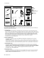


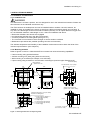
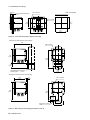
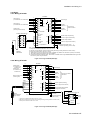

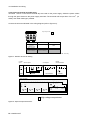
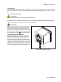

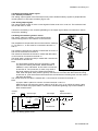
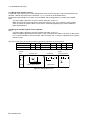
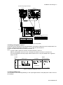

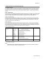

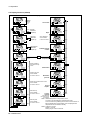
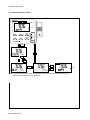
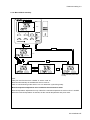

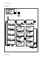

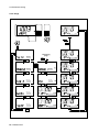
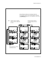

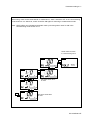
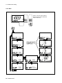
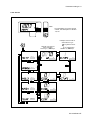
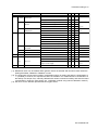


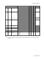

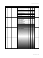
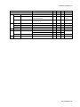

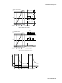
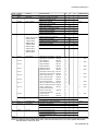
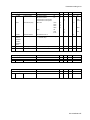

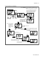
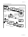

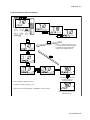
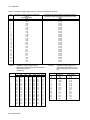

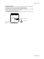

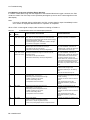
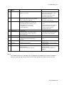


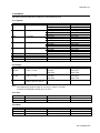
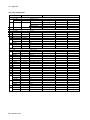
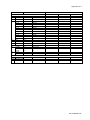


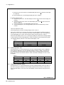

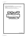
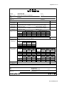

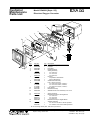


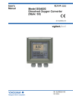


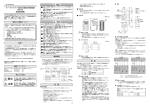


![Model ISC450G [Style: S2] Inductive Conductivity](http://vs1.manualzilla.com/store/data/005904832_1-e9e6bdf8409b6fd37a184b6e2701b530-150x150.png)


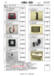

![Model PH450G [Style: S2] pH and ORP Converter](http://vs1.manualzilla.com/store/data/006013412_1-cd77700eed276036ffccc744cbf6fbb4-150x150.png)