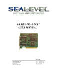
1
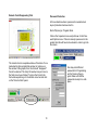
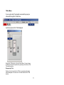
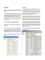
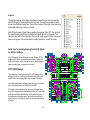
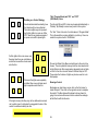
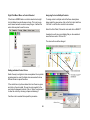
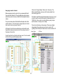
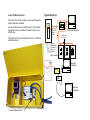
Graphical Interface Software
User’s & Programmer’s Manual
Unity GX User’s Manual
Index
System Requirements
Installing the Software
Opening Unity GX
Starting the Program
Reconnect at Start Up
Connecting Via RS 232
Connecting Via Ethernet
Demo Mode
In RUN Mode
Moving Graphics, Two Mouse Modes
“Zoom Extents” when Picture Disappears
Multiple Graphics Pages
Multiple Sites
Programming Via Unity GX
Schedule Menu
Modifying an Existing Schedule
Remote Clock Disappearing
Password Protection
Thermostats
Page 1
Page 2
Page 3
Page 4
Page 4
Page 4
Page 5
Page 5
Page 6
Page 7
Page 7
Page 7
Page 7
Page 8
Page 9
Page 9
Page 10
Page 10
Page 11
Unity Programming Manual
Getting Started
The Bus File
Graphics and Guidelines
How Unity GX Works
Preparing a Graphic for Unity GX
Types of Graphics
Opening GX for the first time
Programming a New Site
The Layer Menu
Layer Colors
Page 13
Page 14
Page 14
Page 15
Page 16
Page 17
Page 19
Page 19
Page 20
Page 21
Page 21
i
Two Mouse Modes
Zoom Extents when Pic Disappears
Drawing Controls, Control Mode
Deciding on a Control Strategy
Global Color Controls ON, OFF, IDLE
Drawing a Control, Rectangles
Drawing a Circle
Drawing a Polygon
Do not Zoom While Drawing
Ensuring a Speedy Response
Copying, Modifying, Moving a Control
Deleting a Control
Setting Individual Control Colors
Assigning Loads to Controls
Naming Controls
Toggle or ON or OFF
Colors in RUN MODE
Information Bar
Adding Graphics
Importing Additional Graphics
Page 22
Page 22
Page 22
Page 23
Page 23
Page 23
Page 24
Page 24
Page 24
Page 24
Page 25
Page 25
Page 26
Page 27
Page 28
Page 28
Page 28
Page 28
Page 29
Page 29
Appendix 1
One Line Diagram
Link to PC-Ethernet Card
Link to PC-RS 232 Card
Tech Support
Page 30
Page 31
Page 34
Page 35
System Requirements:
1) GR 2400 lighting Control system up and running and
able to be controlled remotely via a modem. This is so
that the factory can dial in and make sure everything is
correct.
Unity GX Graphical Interface Software is designed to work
with Lighting Control & Design’s GR 2400 Lighting Control
System.
2) The Bus file for this GR 2400 system laid out in Unity
Software.
Once installed it provides a very simple way of communicating large quantities of data as to the status of the lights
controlled by the GR 2400 Software.
3) A Link 2 PC (RS 232 or Ethernet) card that is attached
to the GR 2400 bus.
A simple click of the mouse on an area will change the status of the lights in that area. Though the default colors may
be changed it is usual to set the ON color to yellow and the
OFF color to gray.
4) An IBM Compatible computer with at least 512 Meg of
memory running under under Windows XP or any version of windows later than Windows 98.
The faster the processor the better. However anything
over 2.4GHz will be adequate for running the system.
5) As large a monitor as possible. The monitor should be
set to a screen resolution equal to or above 1024 by
768.
6) A scroll Mouse. Zooming IN and OUT is done by use
of the scroll wheel. Though one can click and drag to
zoom in it is a lot easier to have the right mouse.
The software may be configured to come up in run mode
with the only requirement to get it up and running is that
one double click on the Unity GX Icon on the desk top.
This manual helps you get to that point.
1
Installing the software.
3) Installing a new Version of Unity GX:
1) If this is the first time the software has been installed on
this computer go to step 3.
Unity GX will be provided either on a CD or over the
Internet in an e-mail or downloaded from a site on the web.
2) If there is an earlier version of the software on the computer there are two types of update.
CD Install
a) Complete Install Update.
This requires that the previous version of Unity GX is UN
INSTALLED first. Go to START/CONTROL PANELS/ADDREMOVE PROGRAMS and click on Unity GX. This will Uninstall the program and you can move to step 3. You may
also need to either rename or remove the “lcd database”
folder in your C: directory before installing UNITY GX again.
Instructions will come with the new disk.
The CD is set up for “Auto-Run.” Put it into the Computer’s
CD Player and click on “Yes” or “OK” in all the prompts and
the Program will be installed automatically. If LC & D has
pre programmed your graphics for you these will also be
installed on your C drive in the “lcd database” folder.
If the computer is properly connected to the system then
you are now ready to start.
(See Appendix 1 for how to connect the computer to the
GR 2400 network.)
Computers without Auto Run Enabled or Files sent by
Internet.
b) “EXE Update.”
In this situation an upgraded version of the software has
been provided, usually via e-mail, and one can just paste it
into the UNITY GX folder that is on the C drive under PROGRAM FILES. This will over write the old file. When it asks if
you wish to replace the file with the newer version please
click on OK. The program will be immediately available for
use at that point.
2
If your computer does not have the Auto Run feature
enabled or if the files were sent over the internet or downloaded then the CD or the inside of the folder will look like
this:
Opening Unity GX.
Double Click on “Set Up” and the program will install by
itself.
If your computer is missing any basic files in the operating
system you may be required to load these first and then
restart the computer and repeat the process.
Notice the difference between the Unity GX logo and the
Unity Software Logo.
If LC & D created graphics pages for you these will be
installed on the C drive in a folder called “lcd database.”
Inside this folder is another one called “sites” and inside this
folder is the site data with the Graphics files and database.
At the end of the install you will see a notice that notifies
you that the installation was successful.
There will be a Unity GX Icon on the Desk Top
If LC&D did not create graphics for you the lcd database
file will be created the first time Unity GX is opened. The
instructions for creating a new site are in the second half
of this manual in the Programming Section. Read through
the operations part of the manual before starting to program in order to get a better idea of how the system works.
3
Reconnect at start up.
Starting the program
Double Click on the Desk top icon and the program will
start. Unity GX opens in “Program mode.” If a password is
requested then please provide it. If the Graphics were programmed by LC & D there will be no password but this can
be added by pulling down the menu under “Supervisor.”
More on Passwords later.
Program mode is the mode in which programming is done,
this will be gone into in the second half of the manual. In
order to get a better handle on programming it is first necessary to be familiar with the use of the program. Also this
part of the manual is for those who have had the system
pre-programmed by the factory. The program mode has
only minor significance to that audience.
The other modes for Unity GX are:
Run Mode (Connected)
Run Mode (Unconnected/Demo)
There are two ways to get the program into “Run” Mode.
If there is no reason to go into the program mode one can
set up the system to automatically connect at start up. This
can be set up with a password which is covered later.
Reconnect at Start up is under the Action Menu and may
be toggled ON or off each time it is selected.
Connection Menu
The Connection menu is titled “Connect to a Clock.” A
Clock is the central processor of a GR2400 system. Thus
connecting to a clock is connecting to the system.
Link to PC (RS 232)
There are several choices to choose from. If your computer is connected via RS 232 then use “Commport via Linkto-PC.”
1) Click on the Program/Run Button.
2) Pull down the Connection menu and choose “Connect
and Run”
Use the “Attempt @ 115200cps.” Usually the Comm Port is
Comm 1 but if this does not work try each of the other
Comm ports up to 4.
4
After Clicking on “Connect” the status button will blink until
the system is connected. The “Connect to a Clock” Menu
will disappear and the Screen will return to Program Mode
for a moment while a connection is being established.
Then the Controls will change from the Program mode
color to the Connected mode colors which show status.
Demo Mode
If the system fails to connect you will be asked if you wish
to go into “Demo Mode.” In this mode one can demonstrate the software but nothing happens in the field. This is
sometimes useful to train new personnel while not actually
flipping lights on and off throughout the facility.
Link-to-PC-Ethernet
If your computer is connected by Ethernet then Choose
Ethernet via Link to PC. This menu then comes up. The IP
address and the Port Number must be filled in.
The instructions that come with the Link to PC/Ethernet
must be followed in order to get the correct IP address
assigned to the card and any port number that is needed in
order to access the card through a fire wall. (That is the TCP
Port #.) This may take liaising with your network administrator to get this sorted out. If the IP address is known in
advance the factory can install it before sending.
Once the IP Address and Port Number have been
filled in press the “Save Settings” button to save having to fill in the data again.
Connected to the System.
While working on connecting to the system the “Connection
Status” window will blink and finally turn green once it connects. There will be a few moments required for the program
to acquire the status of each load and update the display.
5
This is the display of a typical system. To change the status of the lights in an area simply click on that area and it will
change color. Various comments have been overlaid below to bring attention to points of interest.
In RUN Mode
Thermostat Control
Clock Emulation
Access other pages
Fit to Screen
Click on a Zone to Change Status
When the cursor “Mouses Over” a zone the data on
that Zone and what relays are associated with it are
displayed in the information bar
Shows system is still connected.
It is possible for the connection
to “drop out.”
Connected
6
Moving Graphics, the two Mouse Modes.
Multiple Graphic Pages
The Normal mouse control is the outlined cross:
In this mode one can select items. Click on the
surface of the Graphic once to calibrate the graphic and one
can now zoom in and out using the wheel on the mouse. Click
and drag across an area to zoom in to that size and fill the
screen.
A system that has more than one floor or a layout that does
not easily fit into one screen may need multiple Graphics.
Right Click on the mouse to change modes.
The Cross Hairs indicates that one is in PAN mode.
Now clicking and dragging will move the graphic around the
screen. The Scroll function still zooms. In PAN mode one cannot select controls, one can only select menu items.
Access the additional Graphics by pulling down the Window Menu.
The only proviso is that all the graphics are controlling
relays that are all on the same GR 2400 Bus..
Zoom Extents when the Picture “Disappears”
If the picture has disappeared click on the “Zoom Extents” button to put the picture at full size on the screen. The picture can
disappear if one in-advertently clicks and drags just a very small
area and zooms into a white space.
Multiple Sites
Zoom Extents Button
A system that has multiple buses, each one a self contained GR 2400 system may be accessed through Unity
GX without exiting the program.
Click on the surface to recalibrate the Mouse
For example “Demo Complex” could be one of a chain of
“Demo” stores that is located in the town of Complex.
The “Demo” chain has all their stores accessible over the
internet and has programmed a separate gateway
through the fire wall in each of their stores to the Lighting
Control system.
When the Graphic is first opened and occasionally after doing
some of the actions the Mouse “does not know where it is.” Click
on any point in the graphic and the Mouse will “recalibrate” and
the scroll feature may be used again.
7
The way to move from store to store and system to system
is return to PROG Mode, pull down the file menu and
choose the next store. Then choose “RUN” mode and connect over the internet.
Changing a Schedule or programming the GR 2400
System from Unity GX.
Unity GX allows one to remotely program the GR 2400
System. One needs to have read how to program the
GR 2400 system in the GR 2400 manual.
Once the system is in connection mode click on the “Remote” Menu
In order for the different locations to turn up in the file menu
there must be a separate folder for each of the systems in
the Sites menu under “lcd database” on the “C” Drive.
An Emulation of the GR 2400 Clock will appear. Clicking
on the buttons is the exact same as pressing a button on
the clock. In this way the whole system can be programmed.
The first Click on Tab Down will turn on the back light in
the display. The next Click will take you to the user menu.
Click on “Enter” with the “Review Schedule” Menu Highlighted.
8
By Day Menu: This menu
allows for different ON and OFF
times to be set for every day of
the week. Additionally there is
more control over the holiday
schedules and further one may
limit the schedule to certain
parts of the year.
The Schedule Menu
Modifying an existing Schedule
Tab down to the Schedule that you wish to change and
click on ENTER.
Since the factory will have put in most of the required
schedules at start up it is most likely that the first action
needed would be to modify one of the schedules.
There are three types of Schedule:
Navigating around the clock is simple.
Every Day. Only enter an ON and an OFF time and that
will be repeated every day.
Tab Up or Down to Select a Field. If the filed has data that
can be modified then the Scroll Up and Scroll Down Buttons can be used to change the data.
Mon-Fri. Sat, Sun. In this schedule there may be different
ON and OFF times for the three different periods in the
week.
If the field is the title to a menu pressing Enter will take
you to that Menu.
Go back by pressing EXIT. The SAVE Function will usually
be accomplished by EXIT but very occasionally require
confirmation by pushing the ENTER button. For instance
when exiting a Schedule after changing something the
screen will look like this:
Press ENTER to say YES or tab to NO and press ENTER.
9
Remote Clock Disappearing Trick
Password Protection
In those situations where a password is needed a dual
layer of protection has been built in.
Start off by being in Program Mode.
Click on the Supervisor menu and pull down to the Password Options menu. If there is already a password on the
system then this will have to be entered in order to get into
the screen.
The remote clock is a separate window of fixed size. If one
inadvertently clicks outside that window, for instance on
the window of the graphic, then the clock will “disappear!”
Do not be alarmed. The Unity GX window has just come to
the front since it was Clicked. To return the Clock to the
front window position go to the bottom menu bar and click
on the “Remote Clock” panel.
10
One may enter different
passwords for Programming
and for Running the program. Make sure that the
passwords are kept in a safe
place.
T-Stats Menu
If your system has Thermostats connected they may be
accessed through the T-Stat Menu.
A window opens with a T-Stat displayed.
Select which T-Stat to look at from the Select Menu. One can change
the Mode and the Set Temperatures by pressing on the buttons of the
Thermostat emulation.
Disappearing T-Stat
Similar to the clock emulation the T-Stat is a separate small window
and will disappear to the menu bar if one clicks outside of the T-Stat
window.
11
12
Unity GX
TM
A d va n ce d Gra p h ica l S o ftwa re
Pr og r amming Manual
13
The Bus File
Getting Started
If your system was pre-programmed by Lighting Control &
Design.
If you purchased Graphical pages programmed by LC&D your
Unity Disk will contain an additional folder called “lcd database.“ This file will automatically be copied onto your C drive.
Unity must see this file in the C directory, it cannot be inside
another folder. If you wish to add pages or redo the site then
continue reading.
If you will be creating your own Graphical Pages:
Unity GX uses the “Bus” file created using our Design Utility
called “Unity.”
This file will have been included on the Unity GX disk or has
been e-mailed separately. If you do not have the file please
call (800) 345-4448 and ask for Tech Support. Please note
that LC & D files projects by name and not by a PO number.
Before using the Bus file it should be opened in Unity and
inspected.
14
The Bus file shown below left is a typical Bus file. In this case we
are using an example of a retail store. The Zone Numbers have
been filled in but there are no descriptive names for each of the
loads. Though this may be fine for the electrician who has the
plans it will be very confusing for an end user.
Unity GX uses the descriptive names of each of the loads as the
default name for a “Control.” A “Control” is an area on a picture
that controls a relay or set of relays in the system. These controls
MUST have different names or they will be combined together.
In the next illustration the same bus file has been filled out with
descriptive names so that it can be used. Your Bus file should also
be filled out in a similar way if it has not been already. Additionally
any name that is identical needs to be modified to add numbers
after it to make it unique.
Note how the three Cash Register loads have been numbered to
ensure different names.
Graphics
The most important part of the display is the Graphics that will be used. One can import the
AutoCAD file used by the electricians to wire the project. The page that is usually the best to
choose is the “Reflected Ceiling Plan.” This will show the layout of the lights. It may need some
considerable polishing up in order to be usable.
AutoCAD has hundreds of layers that are capable of being turned ON or OFF. One should get
the cleanest drawing possible from the Architect or Engineer who laid out the project. The
instruction sheet sent to clients who have LC & D do the graphic pages for them is reproduced
below since it gives a lot of important data for creating Graphics for use with the system.
Guide Lines for providing drawings for Unity GX Graphical Interface Software
LEASE
MANAGER
178
FLEET
OFFICE
175
FLEET
OFFICE
176
UP
ROOM
103
FLEET
Unity GX Graphical Interface Software runs under Windows XP. The
purpose of the Software is to present large quantities of lighting data
rapidly to the operator so that he or she can see the status of groups of
loads or individual loads in a lighting control system.
LOBBY
100
174
FLEET
OFFICE
173
The starting point for most systems is the Auto CAD drawing that the
building was built from. Particularly the Reflected Ceiling Plans which
contain the data on the lighting that is being controlled in the space.
Auto Cad Drawings contain hundreds of layers which are each named
with a criptic reference such as 21$0$A-FLOR-LOCKER.
FLEET
OFFICE
172
CLOSING
OFFICE
180
CLOSING
OFFICE
114
COPY
ROOM
171
CLOSING
OFFICE
181
CLOSING
OFFICE
113
STORAGE
184
HALL
177
CLOSING
OFFICE
152
BUSINESS
DEVELOPMENT
OFFICE
151
15
WASHRM
106
BATHROOM
107
INTERN ET
OFFICE
115
SHOWROOM
101
CLOSING
OFFICE
182
KID'S
ROOM
112
CLOSING
OFFICE
183
CLOSING
OFFICE
111
SECRETARY
108
INVENTORY
OFFICE
109
HALL
110
CLOSING
OFFICE
153
CLOSING
OFFICE
131
CLOSING
OFFICE
132
USED CAR
MANAGER
120
HALL
145
STOR
166
STOR
167
CUSTOMER
OFFICE
164
STOR
130
MEN'S
LOCKERS
133
GENERAL
SALES
MANAGER MANAGER
154
129
CLOSING
OFFICE
165
CHAIR
STOR
149
On the right is shown a section of the Layer menu for the plan shown
below. Even though there is a layer labeled as “WALL-EXT” which might
be thought to be Exterior Walls this layer in fact contains only a few of
the straight lines in the exterior walls. The exterior walls need 6 other
layers turned on to show them all. Similarly for lights and other features
of the plan.
INTERNET
MANAGER
117
RECPT.
LEASE
OFFICE
179
CLOSING
OFFICE
170
ELEC
150
VEST.
163
HALL
145
VEST.
159
CUSTOMER
OFFICE
158
CLOSING
OFFICE
155
F&I
OFFICE
128
MENS
162
WOMEN
TOILET
135
STOR
161
F&I
OFFICE
127
WOMENS
160
WOMEN
LOCKERS
136
CLOSING
OFFICE
156
F&I
OFFICE
124
CLOSING
OFFICE
157
TRAINING
ROOM
148
PANTRY
147
FOOD PREP
146
CLOSING
OFFICE
116
OWNER'S OFFICE
105
HALL
102
LEASE
OFFICE
185
AUTO CAD Drawings
COPY ROOM
104
MEN'S
TOILET
134
WORKOUT
ROOM
121
STORAGE
137
HALL
126
JAN.
140
VEST.
139
VEST.
138
EMPLOYEE
LUNCHROOM
122
F&I
OFFICE
125
F&I
MANAGER
123
How Unity GX works.
Unity GX is a program that takes a DWG (or dxf or Bitmap or Jpeg) drawing from Auto cad or other program and overlays
“CONTROLS” on top of this drawing.
A “CONTROL” is just an area of color that represents the status of the light or lights in that area. Typically the OFF color is gray and
the ON color is a light yellow. These colors have been found to be the most universally understood colors particularly with color blind
people who have trouble with Reds and Greens. The end user may specify any color they wish within the 256 color palette to represent ON and OFF but all the examples shown will use these colors.
The CONTROL is linked to a relay or collection of relays and when the system is connected will represent the status of these relays.
Clicking on the CONTROL changes the status of the relay or group of relays. A CONTROL may be designated as an ON ONLY, OFF
ONLY or TOGGLE type CONTROL.
In order for a person to program Unity GX they must
know what lights represented on the plans are controlled by what relays. This should have been specified
LOBBY
100
in the UNITY Bus file which lists the relay panels and
the loads controlled.
In a perfect world the contractor will have connected all
the relays exactly as per the plan. Unfortunately this
does not always happen and is one of the variables that
have to be taken into account.
RECPT.
OFFICE
179
CLOSING
OFFICE
180
CLOSING
OFFICE
114
CLOSING
OFFICE
181
CLOSING
OFFICE
113
STORAGE
184
INTERNET
OFFICE
115
SHOWROOM
101
CLOSING
OFFICE
182
KID'S
ROOM
112
CLOSING
OFFICE
183
CLOSING
OFFICE
111
The illustration on the left shows some of the ways
one can represent a CONTROL. Some lights are
shown as ON and some as OFF.
Please notice that the individual fixtures can be
shown as filled in with color or a broad band can be
drawn over the fixtures or of the entire area to represent the status of the lights in that area.
It all depends on how the area is circuited. If it is a
small room with all the lights on one relay then coloring the whole room would makes sense.
16
LCP 1-21
LCP 1-22
STORAGE
184
CLOSING
OFFICE
182
CLOSING
OFFICE
183
LCP 1-24
If however there are may different levels of switching within the area then
LCP 1-26 coloring in the individual fixtures may make more sense.
Sometimes the plans show the fixtures are circuited alternately but are in
fact wired on one circuit with alternate rows on different relays because
“this made more sense” to the electrical contractor. This is why Lighting
Control and Design requires a print out with the lights that operate together
LCP 1-25
circled and the relay that controls them written within the circle.
LCP 1-27 Usually there is already an Auto Cad file that shows these circuitings but
they are designated as going to particular breaker numbers. The breaker
numbers should be substituted by relay numbers so that there can be no
ambiguity in providing the graphics.
Preparing a drawing for use with Unity GX.
The drawing shown on the first page in fact has some 50% of the available layers turned off and even so it would not be
acceptable for use as a Graphical control page. There are so many lines in it that it would be confusing. Lighting Control
& Design can only use drawings that the end user has seen and signed off as being what they want to see in the Graphical control software. A form is provided at the end of this document that can be used as a sign off sheet.
Here are some guide lines to assist in preparing the document.
a) Turn off all the layers you do not want to see in the end product. The only exception might be the layers showing the
circuiting. However this layer must be plainly marked in the layer menu so that it may be turned off later.
b) Any area that is to be covered with a CONTROL should not have any colored patches in it. The software reverses the
color when doing an overlay. Thus a yellow area will turn Blue. This adds confusion.
c) Try to keep the drawings as uncluttered as possible.
d) Any labeling or naming of parts of the Graphic should be done in the Auto Cad document. This includes the addition of
“Buttons” that may be drawn on the page such as an “ALL ON” or “ALL OFF” Button.
17
Preparing a drawing for use with Unity GX (Continued.)
e) Unity GX has powerful PAN and Zoom features so you may be able to go right down to the individual
fixture level. This may not be so visible in actual use so think of the way it will be used by the end user
and if the data can be displayed so that the end user can see at a glance what is going ON.
f) Remember that if you did not tell Lighting Control and Design about some special feature that is
wanted that they will not be able to provide it for you. Please document all requests and we will do our
best to provide it.
g) Rename the cleaned up files for each floor with an end user name. For instance E793-0 may not be
immediately obvious to the Security Guard who needs to turn on the lights as being the Basement. The
file should be renamed “BASEMENT” and the Graphic itself should have in large letters the word “BASEMENT” or “First Floor” or whatever so that the end user can instantly know what he or she is looking
at. Remember that lights should be considered a Life Safety system and as such should be instantly
usable.
h) Aspect ratio. The Unity GX Screen has data above and below it with the center available for graphics.
Thus a horizontal “Wide Screen” format of 16 to 9 is the best proportions to use. Tall vertical drawings
will have to be scaled down to fit full screen. Consider rotating such drawings to landscape view to
make the more easily viewable.
i) Auto cad files are frequently made up from libraries of special shapes used by a particular engineer.
There are other files too that are separate from the drawing such as “Xrefs” and Fonts. These must all
be provided in the folder that contains the drawings themselves. Failure to provide these files means
that they cannot be viewed.
j) Ensure that the checklist on the last page is filled in and attached to the plans when they are sent.
If the person who is working on filling these requirements has any questions please have them contact
Lighting Control & Design at our Tech Support Hot line (800) 345-4448 and ask for help with Graphical
Controls.
Chief Engineer
18
Lighting Control & Design
Types of Graphics
Opening Unity for the First Time
Unity GX can import many types of Graphics. The available
types are:
.dwg
.dxf
.dwf
.jpg
AutoCAD native format graphics
Document eXchange Format (Also an AutoCAD type
format.)
AutoCAD format for the Web
Picture format.
Only the .dwg format allows manipulation of the colors of each
layer from within Unity GX.
Once the Bus file and the Graphic(s) are available we are ready
to begin.
The window above will come up in the center of the screen.
Double Click on the
Unity GX Icon on the
Desk top
This screen can also be accessed from the ABOUT menu at any
time and the data filled in later. Please fill in your customer
name. If you wish to use the Scheduling capabilities of the software this has to be purchased separately and a Key code will be
sent to you to unlock that capability.
After putting in the company name close this window by clicking
on the “X” box.
19
Programming a New Site
A typical Windows menu will appear allowing navigation of the
hard drive. Find the bus file that was created earlier for this project. Once you have found the file click on “Open.”
This is what the opening screen looks like if there are no files
already programmed. The simplest way to show how to program
Unity GX is to actually walk though programming an application.
A warning appears about the password. Click OK.
In the top left hand corner pull down the file menu and select
“New Site”
20
Either input a password or leave it blank. If it is left blank the
program will allow anyone with access to the computer to operate the system. A password can be entered later using the
SUPERVISOR Menu. Once again click “OK”
The Layers Menu
If the Graphic is in .dwg format the
layers menu allows for turning off
unneeded layers and for changing
the color of other layers.
A new Window opens prompting for the Graphic file. It will usually open in the same folder that the bus file came from which
may require navigating to another area. If the file format window
is not correct pull down and select the file format you are using.
Make sure the name of the file shows in the top window and
click on “Open.”
The layers to be removed may be
selected by clicking on the check
marks in the boxes. The menu
shown is typical of any AutoCAD document. The names of each
layer are extremely criptic and only have meaning to the person
who created them. Frequently one can turn off a layer and it
appears that nothing has changed, and indeed nothing may
have changed or just the corners of some object have been
modified. It is wise to turn off all layers that do not help understand the layout of the lights and what needs to be controlled.
Layer Colors.
The Color of each layer may also be modified. Clicking on the
color of a particular layer brings up the color pallet:
Choose the color or shade of gray and click on “Select.”
To illustrate a point the picture has been pushed up into the top
left hand corner. Notice that the lines are quite heavy and that
there are Grid lines with letters that are distracting. The Grid
makes seeing the graphic more difficult. Since this graphic was
in dwg format the “Layers.” Menu is available. It is not available
in other formats.
21
Zoom Extents when the Picture “Disappears”
If the picture has disappeared click on the “Zoom Extents” button to put the picture at full size on the screen. The picture can
disappear if one in-advertently clicks and drags just a very small
area and zooms into a white space.
Zoom Extents Button
Drawing Controls, CONTROL MODE
A control is an area on the graphic that will change color to indicate if a light or set of lights is ON or OFF.
Using the “Layers” Menu the outlines of this graphic have been
changed to Gray. The Lights themselves have been left with
black outlines. This allows the person who will control the
graphic to see where each light is in relation to the building
while not having such a busy screen that it is not possible to
make out what is going on.
Next to the Program Button is a grayed Arrow. Clicking on the
“Arrow” Button changes it from Gray to Green. This means that
Control Mode is Active.
Moving Graphics, the two Mouse Modes.
The Normal mouse control is the outlined cross:
In this mode one can select items. Click on the
surface of the Graphic once. This is to calibrate the graphic and
one can now zoom in and out using the wheel on the mouse.
Click and drag across an area to zoom in to that size and fill the
screen.
Rectangle
Circle
Polygon
Individual Color Selection
Only in “Control Mode” (when the arrow is green) may one draw,
change, duplicate or delete a control.
Right Click on the mouse to change modes.
The Cross Hairs indicates that one is in PAN mode.
By selecting the right tool one can draw a Rectangle, a circle or
Now clicking and dragging will move the graphic around the
a polygon. The Polygon control is the most useful.
screen. The Scroll function still zooms. In PAN mode one cannot select controls, one can only select menu items.
22
Deciding on a Control Strategy
One should decide before starting how
the Graphic will look once finished.
There are multiple ways of representing that the lights in a room are ON or
OFF. Take the very simple example of
a square room with 4 square lights.
If all the lights in this room come on at
the same time then one could draw a
control that covered the whole room in
color like this:
If however the lights were separately
controlled then one could make each
light a separate control like this:
“Idle” (Program Mode) and “ON” and “OFF”
(RUN Mode) Colors
The Idle and ON and OFF colors may be selected individually or
“Globally.” By Globally is meant every control in the system.
The “Idle “ Color is the color of controls when in “Program Mode”
This is the mode the program defaults to on start up. Once connected to a system one is in “RUN Mode.”
Choose the Global Color Menu and pull down to the color to be
chosen. The color pallet will come up and the color selected will
be the Global color. We recommend a pale pastel such as Salmon Pink for the Idle color and Yellow for ON and Gray for OFF.
These make the functions of lights very obvious even for color
blind people.
Drawing a Control
Rectangles can start at any corner, click on the first corner to
locate that point. Then click on the opposite corner to complete
the control. The Box shape will be drawn to show where it is
going to be and once the second click is entered the rectangle
will be filled in with the idle color.
If the lights are very thin they may not be visible when zoomed
out. In which case it is often best to exaggerate the size of the
control for additional visibility like this:
23
Drawing Circles
Do NOT ZOOM while drawing.
Select the circle from the Green Arrow menu. Start drawing by
clicking on the center of the future circle. Then move the mouse
out to the right radius and click again to complete.
Do not zoom in or out while drawing a control. This will cause
the program to loose its place and the outline that had been
started will disappear. To recover, click on the Green arrow twice
to change it via gray back to green.
Note that after each control the Green arrow changes to Gray
and one has to click on the arrow again.
Drawing Polygons
Click on the Polygon symbol under the green arrow. Starting
from one corner of the object start clicking around the edges of
the object until all that is left is a straight line to the first point
clicked. Right Click to complete the Polygon.
Ensuring Speedy Response
The number of controls in a “site” is limited to 1250. However
this number of controls will respond rather slowly even with a
very fast computer. The smaller the number the faster the
response.
The Polygon tool can be used to draw multiple controls as one.
These controls must all act together. For instance take a row of
lights that are alternately switched.
b
a
CLICK
CLICK
CLICK
CLICK
CLICK
CLICK
CLICK
CLICK
CLICK
CLICK
CLICK
CLICK
CLICK
First
CLICK
b
a
The clever way to draw a control to handle these lights is to use
the Polygon tool as shown below:
CLICK
CLICK
b
a
CLICK
CLICK
Then Right CLICK
to Complete Polygon
CLICK
CLICK and then
Right Click
The end result will be one control with three areas. The places
where the line goes over the top of another line do not show.
CLICK
CLICK
24
Copying Controls
Modifying a control
The lights in a ceiling are frequently of the same shape. Once
one has been drawn it can be copied and pasted to other locations. Zoom out sufficiently to be able to see multiple lights that
need to be copied to. One may not zoom during the copy operation.
If when copying one finds that some of the objects copied to are
not identical and the control could do with some “tweaking,” do
the following.
Click on the Arrow to make it green. Then Click on the control.
Now move the “handles” around to achieve the desired shape.
Turn the arrow green by clicking on it. Now click on the shape to
be copied so that it turns into an outline with “handles” on each
corner. Now Right Click and choose Duplicate
One may click off the first control and click onto another one
without having to change the status of the Green arrow until one
has modified all the controls that need it. Click on the Green
arrow again when done.
Moving a Control
This can be done in two ways. The formal way is to make the
Green arrow active, click on the control to be moved and then
right click and choose MOVE.
The other way is to just click and drag on one of the lines of the
outlined control and the whole control will MOVE.
The outline of the object will now be attached to your pointer
with a dimension line from the point of clicking. The next click
will copy that object to that location. One can continue copying
until done. Click on the Green arrow to drop the object.
Deleting a Control
As before, highlight a control. Right Click and choose DELETE.
The control will disappear.
Properties
Click Green Arrow
to finish
The right click pull down menu has an item called “properties.”
This does nothing at this time.
Dimension Line
Duplicate Object being moved
25
Right Click Menu When no Control Selected
Assigning Colors to Multiple Controls
If the Arrow is GREEN and no control is selected and a right
click is initiated one gets the menu shown. This is not a very
useful menu because one can do everything on it without the
extra clicks required to use this menu.
To assign colors to multiple controls that have already been
drawn select the green arrow, click on the first control and then
“shift click” on all the other controls to be selected.
Select the Color Pallet, Choose the color and click on SELECT.
A warning box will come up indicating that you have selected
more than one control. Click on OK.
The colors will now all be changed.
Setting individual Control Colors
Three Controls Chosen
Earlier the way to set global colors was explained. A very similar
procedure may be used if multiple colors are needed to show
different Zones or special functions.
Then Click on Color Pallet
and SELECT
If the control has not yet been drawn then turn the arrow green
and click on the color pallet. Choose the color needed for the
next and all subsequent controls. Click on “Select” and proceed
to draw the control by choosing a shape and drawing it.
If another color is needed then repeat the procedure.
Click on Yes.
26
Click on the “Assign Relays” button next to the arrow. The
Define Loads Window comes up and the main window functions are all grayed out.
Assigning Loads to Controls
Before assigning loads to controls it is recommended that all
the controls be drawn first. Though additional controls may be
added at any time it has been found that this simplifies the procedure.
The Define Loads Window will almost always have to be moved
in order to see the controls that need to be selected. Click or
“Shift Click” on the control or controls that are going to represent the status of a relay or set of relays.
The picture below shows the Retail Store Graphic with all the
controls drawn in. The next step is to assign relays and a function to each control or group of controls.
At this point it is vital to know what relays control which loads.
Hopefully this step has been done from the naming of each of
the relays in the bus file.
Then click on that relay or those relays. If there are multiple
relay panels in the system one may have to use the LCP
(Lighting Control Panel) Pull down menu to select another LCP.
Assign Relays
Up until now the Arrow Function has been used. It is not needed
and should be gray while assigning relays.
27
LCP Menu
Control Name Matches First Relay Chosen, Overwrite if needed
Colors in “Run” Mode
To cancel without
saving Click here.
Click when done
For individual ON
and OFF colors
when in “RUN”
Mode select here
When Connected to a system in “RUN” Mode the usual color for
ON is Yellow and for OFF is Gray.
If there are multiple relays being switched by a Toggle control
and some of them are out of sync. (Some are ON and some are
OFF) a warning box will ask if the next command should be an
ON or an OFF command. The control will turn Orange to signify
an Out of Sync condition.
ON controls will be ON (usually Yellow) as long as any single
relay in the ON group is ON. All the relays must be off before an
ON control turns to the OFF color. (Usually Gray.)
OFF controls will be the OFF color (usually Gray) unless every
relay in the OFF group is “True” which in this case means OFF.
The Off control will then display the ON Color. (Usually Yellow.)
This logic follows the logic of LC & D Switches.
Naming Controls
Information Bar
If a control has more than one relay assigned then the first one
on the list will be used as the default Control Name. This control
name can be overwritten and saved as something else.
Toggle or ON or OFF?
A Control may have one of three functions. The default is
“Toggle.” When it is clicked all the relays will change state.
The ON or the OFF functions do what one would expect; command relays ON or OFF.
28
The Information bar is located at the bottom of the screen. It
has previously been empty. Now that the controls are assigned
to relays the information will show up in the bar when “mousing
over” a control in the zoom (outlined cross) mode.
The Cross will change to a Hand over each control.
Adding Graphics
Though the almost infinite Pan and Zoom of Unity GX Vector
allows the possibility of getting a whole site onto one page there
are situations where multiple pages make more sense. A multistory building for instance.
Multiple Sites
The site files are kept in a folder on the C drive called “lcd database.” This folder holds another folder called “Sites.” Within this
folder each site has its own folder named with the same name
as the Bus file. Do not change the name once the site has been
created since all the files use this name to locate themselves.
The Window menu pulls down to show the Graphic pages available to a site.
Importing Additional Graphics
To import additional graphics
select Import Graphic under
the Action Menu. Note that
existing Graphics can be
deleted or renamed in this
menu.
Note: The Graphic must be of an area controlled by the same
Bus file. Areas that are controlled by a different Bus file require
a different site to be created.
After the Graphic has been imported a window will come up to
ask if there are any additional files that need to be imported.
This refers to the special fonts and “X-ref” files sometimes
required for an AutoCAD document.
29
Appendix 1
Example of a GR 2400 System
LOAD
How the system goes together.
One Line Diagram
This one line diagram gives an overview of a typical system.
Relay
Breaker
Panel
Neutral
MASTER
Relay
Panel
323
226-6615
Telephone Connection
LC & D systems come pre programmed
from the factory with the data to hand
when we ship it. However at start up
there are usually some minor changes
and some trouble shooting to be done.
If the telephone hook up is available a
factory tech can check out the system
rapidly over the phone. Not having the
phone line connected can slow project
completion.
4 Twisted Pair
Cat 5 Cable
Phone
Connection:
Contractor to
ensure it is
installed.
Write Phone #
on plate
Relay
Slave
Relay
Panel(s)
30
GR PCO
Outdoor Photocell
Electronics
The Cat 5 cable must be looped
through each item on the bus with NO
SPURS!
The items on the bus (switches, panels,
photocell cards, etc.) may be arranged
on the bus in any order, its not important.
2 ea #18AWG
GR2404
Micro Panel
Digital Switches
Locator Light Plus Pilot LEDs
on all buttons including "Off"
buttons.
Make sure there are
"terminators" at each
end of the bus.
Link to PC/Ethernet Card
Typical Hook Up
The Link to PC card is usually not sent until the whole
system has been installed.
Electronics
As long as the bus can reach the Link to PC box then
the system can be controlled. The Bus may be up to
4000ft long.
Personal Computer
MASTER
Relay
Panel
4 Twisted Pair
Cat 5 Cable
The Link to PC Card connects both to the LC & D Bus
an Ethernet Hub.
Phone
Connection:
Contractor to
ensure it is
installed.
Digital Switches
Personal
Computer
L-2-PC
HUB
Personal
Computer
Connect Ethernet here:
31
Setting up the Ethernet Interface
The Link-2-PC/Ethernet uses a Lantronix Brand Ethernet interface
called an “XPort.” In order to control this interface and set its IP address
one needs to install the software on the disk that came with the system.
This software requires that you have the latest updates for Windows
from Microsoft.com. (Press the “START” button and then choose
“Windows Update” from the menu.) You will also need the .NET framework installed and the latest version of Java available from Sun.com.
This may take some time to get your computer all set up. Go to
www.Lantronix.com and click on “Downloads” and then the page for
Device Installer for the “X-Port” to get more information.
Once Device Installer is available and the Link to PC-Ethernet IP is on
the Ethernet network click on the Search Button.
Note that when the Link-2-PC/Ethernet is shipped it is set up so that
the IP address is dynamically assigned. This is to prevent there from
being any argument with the other items on your bus. However for it
to work with UNITY GX it has to have a fixed IP address. The IP
address shown in the above window was dynamically assigned by the
local server.
The first step is to get the correct IP address and the Subnet Mask
from your IT department. Additionally you may need to get a port
number in order to pass through a fire wall.
If the IT department will not give you an IP Address then use the one
that was dynamically assigned for now since it must be free. Either
way the next step is to make sure the “X-Port “ is highlighted and then
click on the button that says “WEB.”
10001
Device Installer will find the X-Port on the network and display it. Note
that there are now icons in the Menu Section.
32
The Circled points should be as shown. The only difference may be that
the local port might not be 10001 if your IT department does not wish to
use that port.
The fact that (for example) 192.168.1.161 came up as a dynamically
assigned IP address means that that address is also a free address. If
the IT department will not give you an address then this address could
be used.
In order to put in a permanent IP address press the “Server Properties”
button to get to the screen below.
If the IP address and subnet mask are acceptable then press the
“Update Settings” button to save these to memory.
UDP or TCP/IP
DISABLE the UDP connection mode.
Remote Connections.
DO NOT put an IP address in the Dedicated Connection Section
under “Remote IP Address.”
This is for the Lantronix to query upon start up. If it gets nothing
back it locks up. Therefore leave this blank!
For a fuller understanding of the Ethernet modem component of the
system please study the Lantronix XPort Manual on the Lantronix
website at lantronix.com
33
Note the IP Address.
Note the IP address and the Port Number so that it can be placed in
the connection menu.
Link to PC Card (RS 232)
Typical Hook Up
The Link to PC card is usually not sent until the whole
system has been installed and the location of the computer that will control the system is known. If the computer is within 25 feet of a panel we can locate the link
to PC in a panel. If within 200 ft of a panel we can
power the Link to PC over the bus cable. If more than
200ft away then a power supply for the Link to PC is
provided.
As long as the bus can reach the Link to PC box then
we can control the system. The Bus may be up to
4000ft long.
Electronics
MASTER
Relay
Panel
Cables.
323
226-6615
The Link to PC is provided with a 6 ft and 25 ft 6 conductor phone cables. These plug into the RJ 11 jack on
the Link to PC card and into the DB9 to RJ 11 adaptor.
Personal Computer
4 Twisted Pair
Cat 5 Cable
Phone
Connection:
Contractor to
ensure it is
installed.
Digital Switches
Relay
This DB9 adaptor should be plugged into the serial port
on the rear of the PC.
Serial Port
34
Personal
Computer
Tech Support
(800) 345 4448
35