1
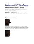
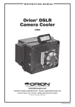
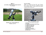
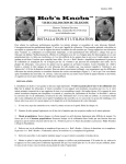
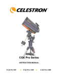
ANALOGIC PC & BIG 35 Analogic_PC
USER MANUAL
ASCOM V1 COMPATIBILE
INSTALLATION
Mechanics – Schmidt-Cassegrain
The Micro Focuser Analogic (MFA_PC) are designed to be compatible with most telescope with a
standard 2 inches barrel, like Schmidt-Cassegrain instruments. The threaded ring must be removed
by hand from the focuser and attached firmly to the telescope. Now the MFA_PC focuser can be
applied to the telescope, rotating it if needed and block it using the three thumbscrews near the
base of the focuser. Along with the MFA_PC two adapters RSWLRQDO, the first permits to insert
eyepieces and accessories with a diameter of 1 ”, the seconds is designed for 2” accessories.
Mechanics – Newton and BIG 35 Analogic_PC
This focuser supports the same accessories of the previous model, not a Micro Focuser BIG 35
Analogic_PC (subsequently appointed BIG35A). To mount the focuser to the telescope use the
supplied plate attaching it with screws at the same place of the previous focuser of the telescope.
Before mounting the MFA_PC it is mandatory to securely attach the plate to the base of the focuser
using the 4 thumbscrews supplied.
Electronics
The MFA_PC or BIG35A are supplied with a cable for the power supply marked by a yellow or
white stripe. Optionally it’s available a power supply with an universal input (110/240 Vac 50/60
Hz). The 8-pins cable between the controller and the focuser is approx. 2 meters long. The RS232
6-pins cable is 5 meters long (maximum length: 15 m) and must be connected between the
controller and the PC, using the DB9 adapter. We recommend to connect the all the cables before
turning on the focuser. If a different power supply is used then it’s mandatory to verify the following
specifications: minimum Vcc: 9 Volt, maximum: 14 V. At least 0.5 Ampere for the current.
CONTROLLER AND COMMANDS
• Power on: Press the central button (PWR)
• Manual power off: Keep pressed the button PWR until
all leds are off.
• Automatic power off: This function is enabled if the led
of the speed blinks (MOTOR SPEED %). To enable this
function press the button PWR until the led stars blinking.
When the focuser is controlled by the PC this function is
automatically disabled. To disable this function keep
pressed the button PWR until the led stops blinking.
• Calibration: This function brings the focuser to the half of
its run, a known position which will can be used as
reference. To enable this function power off the focuser
(keeping pressed the button PWR until all leds are off),
then power it on (always pressing the PWR button and
waiting until the speed leds are on) then press again
PWR while the leds starts going off.
• Speed selection: Press the button SPEED to change it,
the speed is indicated by the leds and it’s expressed as
percentage relative to the maximum.
2
NEW HAND CONTROLLER
• Moving forward: keep pressed the button IN. If the button is pressed for an instant then the
focuser will be moved by a fixed small step.
• Moving backward: keep pressed the button OUT. If the button is pressed for an instant then the
focuser will be moved by a fixed small step.
• Indication of end of run: both leds (in and out) start blinking when the focuser has reached its
maximum or minimum position. The motor will stop moving.
• Indication of low battery: all leds start blinking when the voltage becomes too low, when the
focuser is powered by a battery. The battery must be replaced.
Attention
The MFA_PC focuser with firmware version 1.1 has a more powerful motor which needs more
energy, so it cannot be powered by small internal batteries. The firmware version is written in this
manual and in the PC software click the button “?” in the Setup page. An internal battery can be
inserted anyway, but its duration would be very short and may not be sufficient to move the focuser.
PC CONTROL
This section explains how to operate the MFA_PC or BIG35A from any Personal computer running
Windows™ 98, Me, 2000, XP. This function is very useful when combined with CCD cameras or
when the astronomical instruments must be controlled remotely. Now compatible with ASCOM
platform.
The “SETUP” page let the user to choose the correct communication port and connect or
disconnect the focuser. To connect automatically when the program is executed enable the option
“Connect on start”. To keep the program window always in foreground (e.g. above other programs)
enable the option “Window in foreground”. The button “Calibrate” starts the automatic calibration.
Attention !!! Be careful about cables and connections. A wrong wiring may damage the focuser or
the serial port of the PC. See the following scheme.
3
CONNECTION SCHEMATICS
Power supply
Temperature probe
Controller
Serial port
Focuser
To the PC through the DB9
adapter and the 6-pins cable
9 ÷ 14
Vcc
-
Connect here the 8-pins cable
+
The “CONTROL” page let the user to control the focuser.
• Steps (sec): This section contain some button to move the focuser by a fixed amount of time
(seconds). The effective step of the focuser depends also by the current speed (see below), this
means that 16 steps are possible (4 steps by 4 speeds). The buttons with a red title and a
4
•
•
•
•
•
negative value move the focus inside (IN). The buttons with a blue title and a negative value
move the focus outside (OUT).
Speed: This panel changes the focuser speed, expressed as percentage of the maximum speed
of the motor.
IN: This button moves the focuser inside, at the current speed. The focuser keeps moving until
the button remain pressed. After the last pressure in this direction it appears, to flank of the
written one Moves, the written IN.
OUT: This button moves the focuser outside, at the current speed. The focuser keeps moving
until the button remain pressed. After the last pressure in this direction it appears, to flank of the
written one Moves, the written OUT.
Temperature: This panel shows the current ambient temperature. Click the button it’s possible
to switch between Celsius and Fahrenheit.
?: (setup page) Shows a dialog window with the firmware version and the microprocessor
version.
Driver for the Ascom platform
The version 2.0 of the control software is compatible with Ascom standard http://ascomstandards.org , this makes the focuser controllable from any software which implements this
platform. The main purpose is automatic focusing using an imaging and a focusing program like for
example Maxim DL/CCD. The Microfocuser will be listed in the box “focuser” at the page Setup of
the menu View → Telescope Control Window.
In the Ascom page of the software it’s possible to choose the focuser model (20 for SchmidtCassegrain, 40 and 60 for Newton) inside the panel “Ascom Range”. Remember to perform the
calibration if you modify this setting, which brings the focuser to half of its travel distance, for
example at 20 mm for the Newton 40mm.
The buttons IN and OUT in the panel “Ascom step“ move the focuser step by step, every step is
long 7 ms (approx. 100 µm) for the focuser release 1.2 or 3 ms (approx. 30 µ/m) for release 1.3.
In the panel “Ascom Goto“ it’s possible to move the focuser to a given position.
Please note !!! The Ascom position displayed this way is calculated measuring the movement
time, so it’s approximate. The same numerical position may not be related to the same mechanical
position.
5
TECHNICAL SPECIFICATIONS
ANALOGIC_PC S/C 20 mm, NW 40 mm – BIG 35 40 mm
Focuser
Total travel distance mm
Total travel distance mm - BIG 35
Maximum load
Maximum load - BIG 35
Gear (motor)
Gear (focuser)
Controller connector
Temperature probe ( optional )
Mechanical dimensions max.
Mechanical dimensions max. BIG 35
Operating temperature °C
Calibration sensor
Weight
Hand Controller
CPU
Technology
CPU memory
Ram
EEPROM
Clock frequency
Power consumption max.
Focuser connector
PC connector
PC cable, length
Dimensions
Operating temperature °C
Power supply
Optional power supply
Input
Output
Connector
Certificate
20 S/C – 40 NW
40
3.2 ÷ 4.8 kg (depends by the tilt of the instruments)
13 ÷ 15 kg (depends by the tilt of the instruments)
Stainless steel
Brass
1 x 8 pins RJ45
Digital 9 bit, lin. ± 0,5°C ( -0 / +70 ), cable 50 cm
92 x 86 mm ( Ø x H )
Ø 160 ; L 122 mm (40 mm), L 153 mm (60 mm)
-25 / + 65
Hall effect / neodymium magnet
2,6 Kg. approx. (BIG 35) - A_PC 720 gr. (20 mm), 780 gr. (40 mm)
RISC, PIC Microchip 18F876i
FLASH / EEPROM
FLASH 8K – 14 bit
368 bytes
256 bytes
16 MHz
250 mA
1 x 8 pin RJ45
1 x 6 pin RJ11
5 m – (15 m BIG 35)
(L)104 x (W)71,8 x (H)25,4
-25 °C + 65 °C
Internal battery 9 VDC ( only on request )
Extern 12 ÷ 14 VDC (from the focuser)
100~240 Vac, 47~63 Hz, 0.5 A
12 VDC, 1.25 A, 15W max.
Coaxial plug 5.5 mm (positive in the middle)
UL - CE - GS – CB
Revision : January 2015 – firmware 1.5
Web: http://www.microfocuser.com - E-mail: [email protected]
1999 - 2009 ©
CONNECTOR SCHEMATICS
654321
CABLE AND SERIAL
AD APTER DESCR IPTION
RJ11
CONNECTOR
DE SCRI PTION
DB9 SERIAL
ADAPTE R
1 WHITE
NC
1 NC
2 BLACK
GND
2 BLACK
3 RE D
NC
3 RED
4 GREE N
RX 232
4 NC
5 YALLOW
TX 232
5 YE LLOW
6 BLUE
NC
6,7, 8, 9
SERIAL CABLE 6 PINS
FRONTAL VIEW
87654321
HAND CONTROLLER CABLE 8 PINS
NC
FRONTAL VIEW
TEMPERATURE PROBE (OPTIONAL)
HAND CONT ROLL ER
CABL E DESC RIPT ION
+
DQ
-
CONNECTOR
FRONTAL VIEW
1
GRAY
GND
2
BROWN
MOTOR – NE GATIV E P OLE
3
YA LLOW
NC
9
4
4
GREEN
MOTOR - POSI TIVE POLE
5
RED
NC
6
BLA CK
TEMP ERA TURE PROBE
7
ORANGE
8
BLUE
8
FRONTAL VIEW
7
6
SENSOR
5
1
2
3
4
5
2
6
1
CA LI BRATION S ENSOR
DB9 SERIAL ADAPTER
+ 12 ÷ 14 VCC
6