1
Agilent 218 Solvent
Delivery Module
User Manual
218 Solvent Delivery - User Manual
Agilent Technologies
Notices
© Agilent Technologies, Inc. 2012, 2013
Warranty
No part of this manual may be reproduced
in any form or by any means (including electronic storage and retrieval or translation
into a foreign language) without prior agreement and written consent from Agilent
Technologies, Inc. as governed by United
States and international copyright laws.
The material contained in this document is provided “as is,” and is subject to being changed, without notice,
in future editions. Further, to the maximum extent permitted by applicable
law, Agilent disclaims all warranties,
either express or implied, with regard
to this manual and any information
contained herein, including but not
limited to the implied warranties of
merchantability and fitness for a particular purpose. Agilent shall not be
liable for errors or for incidental or
consequential damages in connection
with the furnishing, use, or performance of this document or of any
information contained herein. Should
Agilent and the user have a separate
written agreement with warranty
terms covering the material in this
document that conflict with these
terms, the warranty terms in the separate agreement shall control.
Manual Part Number
G9300-90001
Edition
01/2013
Printed in Germany
Agilent Technologies
Hewlett-Packard-Strasse 8
76337 Waldbronn
This product may be used as a component of an in vitro diagnostic system if the system is registered with
the appropriate authorities and complies with the relevant regulations.
Otherwise, it is intended only for general laboratory use.
receive no greater than Restricted Rights as
defined in FAR 52.227-19(c)(1-2) (June
1987). U.S. Government users will receive
no greater than Limited Rights as defined in
FAR 52.227-14 (June 1987) or DFAR
252.227-7015 (b)(2) (November 1995), as
applicable in any technical data.
Safety Notices
CAUTION
A CAUTION notice denotes a
hazard. It calls attention to an
operating procedure, practice, or
the like that, if not correctly performed or adhered to, could
result in damage to the product
or loss of important data. Do not
proceed beyond a CAUTION
notice until the indicated conditions are fully understood and
met.
Technology Licenses
The hardware and/or software described in
this document are furnished under a license
and may be used or copied only in accordance with the terms of such license.
Restricted Rights Legend
If software is for use in the performance of a
U.S. Government prime contract or subcontract, Software is delivered and licensed as
“Commercial computer software” as
defined in DFAR 252.227-7014 (June 1995),
or as a “commercial item” as defined in FAR
2.101(a) or as “Restricted computer software” as defined in FAR 52.227-19 (June
1987) or any equivalent agency regulation
or contract clause. Use, duplication or disclosure of Software is subject to Agilent
Technologies’ standard commercial license
terms, and non-DOD Departments and
Agencies of the U.S. Government will
WA R N I N G
A WARNING notice denotes a
hazard. It calls attention to an
operating procedure, practice,
or the like that, if not correctly
performed or adhered to, could
result in personal injury or
death. Do not proceed beyond a
WARNING notice until the indicated conditions are fully understood and met.
218 Solvent Delivery - User Manual
In This Book
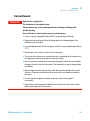
In This Book
This manual contains information on:
• G9300A Agilent 218 Isocratic Solvent Delivery Module
• G9301A Agilent 218 Add-on Solvent Delivery Module
• G9306A Agilent 218 Injection Pump
1 Introduction
This chapter gives an instrument overview.
2 Site Requirements and Specifications
This chapter provides information on environmental requirements, physical
and performance specifications.
3 Installation
This chapter gives information about the installation of your instrument.
4 Using the 218 Solvent Delivery Module
This chapter explains the operational parameters of the instrument.
5 Optimizing Performance
This chapter gives hints on how to optimize the performance or use additional
devices.
6 Troubleshooting and Diagnostics
This chapter gives an overview about the troubleshooting and diagnostic
features.
218 Solvent Delivery - User Manual
3
In This Book
7 Maintenance and Repair
This chapter describes the maintenance of the instrument.
8 Parts
This chapter provides information on parts for the instrument.
9 Cables
This chapter provides information on cables used with the instrument.
10 Appendix
This chapter provides addition information on safety, legal and web.
4
218 Solvent Delivery - User Manual
Contents
Contents
1 Introduction
9
Introduction to the System 10
Physical Layout 12
Pressure Module 14
Pump Head 16
Dual Chamber High Pressure Mixer
Control 23
20
2 Site Requirements and Specifications
31
Site Requirements 32
Physical Specifications 35
Performance Specifications 36
3 Installation
39
Installation
40
4 Using the 218 Solvent Delivery Module
41
Introduction 42
Power On 43
Priming the Pump Heads 44
Creating a Simple Method on an Agilent 218 Pump
Check and Run the Method 46
Method Menu 48
Sample Methods 54
5 Optimizing Performance
45
61
Choose the Appropriate Pump Head for the Application
218 Solvent Delivery - User Manual
62
5
Contents
6 Troubleshooting and Diagnostics
63
Introduction to Troubleshooting and Diagnostics 64
Using the Pressure Display as Diagnostic Tool 65
Troubleshooting Guide 66
7 Maintenance and Repair
73
Introduction to Maintenance 74
Warnings and Cautions 75
Maintenance Schedule 77
Service Logs 79
Adjusting the Flow Rate on the Pump 81
Clearing Air Bubbles from the Liquid Head 82
Removing Seals (Standard Head) 83
Removing Seals (Washing Head < 200 mL/min) 85
Removing seals 200 mL/min Head 87
Replacing Piston Seals (Heads < 200 mL/min) 88
Replacing Piston Seals (200 mL/min Head) 90
Breaking In a New Seal (200 mL/min Head) 92
Breaking In a New Seal (Heads < 200 mL/min) 93
Cleaning Check Valves 94
Replacing Check Valves 96
Checking and Replacing the Mixer Outlet Filter Frit (Analytical and Narrowbore
Mixers Only) 98
Replacing the Mixer Seal 99
Checking and/or Changing Power Fuses (F1) 100
Switching the Mains Voltage 103
8 Parts
107
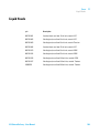
Parts List 108
Liquid Heads 109
Pressure Modules 110
Mixer 111
Standard Accessory Package
6
112
218 Solvent Delivery - User Manual
Contents
9 Cables
113
Cable Overview 114
Cable Connections 115
10 Appendix
117
General Safety Information 118
Solvent Miscibility 124
Solvent Compressibility 125
The Waste Electrical and Electronic Equipment Directive
Batteries Information 128
Radio Interference 129
Electromagnetic Compatibility 130
Agilent Technologies on Internet 132
218 Solvent Delivery - User Manual
127
7
Contents
8
218 Solvent Delivery - User Manual
218 Solvent Delivery - User Manual
1
Introduction
Introduction to the System
Physical Layout
10
12
Pressure Module
14
Pump Head 16
Check Valves
18
Dual Chamber High Pressure Mixer
Control
20
23
This chapter gives an instrument overview.
Agilent Technologies
9
1
Introduction
Introduction to the System
Introduction to the System
A complete modular system includes the pump(s), tubing, mast kit, detector,
and optional fraction collector or autosampler.
This manual is set up to help guide you through an Agilent 218 Solvent
Delivery Module installation, comprising pressure module, mixer (if ordered)
mast kit and tubing.
The Agilent 218 Pump uses proven single-piston rapid-refill technology for
economy, reliability, and virtually pulse-free operation. A range of
interchangeable pump heads allows operation at flow rates from 10 μL/min to
200 mL/min. Biocompatible pump heads are available for those analysts
requiring a completely inert flow path.
A single-channel analog-to-digital converter built in to each Agilent 218 Pump
can convert a detector signal to digital form and transmit the data to a
computer system. Five programmable analog inputs and three programmable
relay outputs are available to further automate the HPLC system. The Agilent
218 Pump is easy to use and very flexible in operation. It can be used in
several different modes of operation: as a standalone isocratic pump, as either
a master pump or a slave pump in a high pressure gradient system, as a
sample inject pump in a preparative system, or in a fully automated HPLC
system controlled by an external computer. In each case, the Agilent 218 Pump
provides outstanding accuracy over its entire range of pressures, flow rates,
and solvents.
The Agilent 218 Pump operates very quietly because of minimal motor noise
and resonance vibrations.
A complete Agilent 218 Pump includes a drive module, a pump head, and a
pressure module.
One of the Agilent 218 Pumps in the HPLC system needs to have a pressure
module installed in its compartment in the pump side panel. The pressure
module dampens pulsations and supplies the current system pressure value to
the drive module. Software in the drive module ensures that the system
pressure is within pre-set maximum and minimum limits. Flow rates are
automatically corrected for solvent-compression effects based on the system
pressure value read from the pressure module and a compressibility factor
entered by the user for each solvent.
10
218 Solvent Delivery - User Manual
1
Introduction
Introduction to the System
The Agilent 218 Pump operates with a variety of 218 pump heads to maintain
specified performance over designated flow and pressure ranges. The easily
replaceable pump heads are self-contained units including a spring-loaded
piston and check-valve cartridges. Pump heads are not included with
individual drive modules.
A complete HPLC system can be controlled either by an Agilent 218 Pump or
PC-based software. When the computer controls pumps, all pumps are slaves
and programming is done on the computer.
On the pump rear panel there is a single RS-422 male connector. This
connector is used for bidirectional signals to and from the controller, whether
the controller is an external computer or another Agilent 218 Pump. Internal
software in the Agilent 218 Pump determines whether the pump is a master
controller or a slave pump.
The possible system configurations (depending on the type of pumps and
controller being used) are the following:
• Isocratic system
• Gradient system with one Agilent 218 Pump as the controller
When several pumps are connected together, the master Agilent 218 Pump
can control the other pumps in the liquid delivery system. A master Agilent
218 Pump can control up to three other slave units: either three additional
pumps in a quaternary system, or two additional elution pumps and one
injection pump. The master Agilent 218 Pump can control other modules in
the system using outputs, and receive information through input contacts.
• Gradient system with HPLC control software as a controller
In this configuration all pumps are slaves and the computer is the system
controller. The HPLC control software controls the pumps via the serial
interface cable and other devices through contact closures on the
Control/Interface module (CIM) built into the Agilent 218 Pump.
218 Solvent Delivery - User Manual
11
1
Introduction
Physical Layout
Physical Layout
DjaZiX]ZX`kVakZ
A^fj^YX]gnhiVaY^heaVn
@ZneVY
EdlZghl^iX]
Ejbe]ZVY
>ca^cZX]ZX`kVakZ
Figure 1
12
Agilent 218 Solvent Delivery Module – front panel
218 Solvent Delivery - User Manual
Introduction
Physical Layout
1
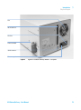
;Vc
7VX`XdccZXidgh
;jhZWdm
EgZhhjgZbdYjaZ
HZg^VaXdccZXidg
EdlZggZXZeiVXaZ
Figure 2
Agilent 218 Solvent Delivery Module – rear panel
218 Solvent Delivery - User Manual
13
1
Introduction
Pressure Module
Pressure Module
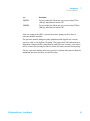
Each Agilent 218 Pump can have a pressure module installed in the panel on
the right side of the pump.
Figure 3
Pressure module
The following pressure modules are available:
14
p/n
Description
393552501
Pressure module, flow: 10 mL/min, max. pressure rating: 599.84 bar
(8700 psi), wetted material: Titanium, FEP
393552801
Pressure module, flow: 10 mL/min, max. pressure rating: 275.79 bar
(4000 psi), wetted material: PEEK, FEP
393552601
Pressure module, flow: 50 mL/min, max. pressure rating: 413.69 bar
(6000 psi), wetted material: Titanium, FEP
393552901
Pressure module, flow: 50 mL/min, max. pressure rating: 275.79 bar
(4000 psi), wetted material: PEEK, FEP
393553001
Pressure module, flow: 100 mL/min, max. pressure rating: 137.9 bar
(2000 psi), wetted material: PEEK, FEP
218 Solvent Delivery - User Manual
Introduction
Pressure Module
p/n
Description
393552701
Pressure module, flow: 100 mL/min, max. pressure rating: 82.74 bar
(1200 psi), wetted material: Titanium, FEP
393650501
Pressure module, flow: 200 mL/min, max. pressure rating: 275.79 bar
(4000 psi), wetted material: Titanium, FEP
1
Only one pump in the HPLC system (the master pump) needs to have a
pressure module installed.
The pressure module dampens pump pulsations and supplies the current
pressure value to the Agilent 218 pump. The pump needs this information to
implement compressibility compensation and flow rate accuracy corrections,
and to ensure that system pressure is within the limits entered during setup.
Choose a pressure module that has a pressure and flow limit greater than the
maximum pressure and flow you will be using.
218 Solvent Delivery - User Manual
15
1
Introduction
Pump Head
Pump Head
Agilent 218 Pump Heads are easily changed, self-contained units including
spring-loaded pistons and check valve cartridges.
Simply loosen a finger-tight clamp to rapidly change pump heads between
analytical and preparative configurations.
Figure 4
NOTE
16
Pump head installed on the pump
The clamp on the 218 pump with 200 mL/min head requires a 1/4 in hex wrench that is
included with the 200 mL/min pump head kit.
218 Solvent Delivery - User Manual
Introduction
Pump Head
1
The following pump heads are available:
NOTE
p/n
Description
R007101061
Pump head, stainless steel, 10 mL/min
R007101062
Pump head, stainless steel, 10 mL/min with piston wash
R007101063
Pump head, titanium, 10 mL/min with piston wash
R007101073
Pump head, PEEK, 10 mL/min with piston wash
393594291
Pump head, titanium, 25 mL/min with piston wash
R007101064
Pump head, stainless steel, 25 mL/min
R007101074
Pump head, PEEK, 25 mL/min with piston wash
R007101076
Pump head, PEEK, 100 mL/min with piston wash
R007101077
Pump head, titanium, 100 mL/min with piston wash
393650701
Pump head kit (218 ONLY), titanium, 200 mL/min
These heads incorporate a second chamber located behind the high-pressure seal. This
chamber, filled with water, literally washes the piston with each stroke. This prevents scale
build-up on the piston that can lead to premature seal failure.
218 Solvent Delivery - User Manual
17
1
Introduction
Pump Head
Check Valves
The pump head in the Agilent 218 Pump has one inlet check valve and one
outlet check valve.
DjiaZiX]ZX`kVakZ
EjbeWdYn
E^hidc
A^fj^Y]ZVY
>caZiX]ZX`kVakZ
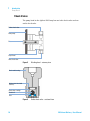
Figure 5
Washing head – cutaway view
Figure 6
Outlet check valve – sectional view
8]ZX`kVakZ]djh^c\
LVh]ZgVcYX]ZX`WVaa
gZiV^cZg
8]ZX`kVakZXVgig^Y\Z
8]ZX`WVaa
HZVi
18
218 Solvent Delivery - User Manual
Introduction
Pump Head
NOTE
1
Inlet check valves are similar to outlet check valves but are installed on the liquid head the
other way up. Both types of valve the check valve cartridge assembly is oriented as shown.
Principle of Operation
The retracting piston creates a negative pressure in the piston chamber above
the inlet check valve. Mobile phase flows upward past the check ball into the
inlet check valve, then into the piston chamber.
As soon as the piston starts to move forward, gravity causes the ball in the
inlet check valve to seat, preventing mobile phase from flowing back out the
inlet check valve. At the same time, a positive pressure is created in the piston
chamber which dislodges the outlet check valve check ball. Mobile phase flows
upward through the outlet check valve while the piston is moving forward.
When the piston retracts again, gravity causes the ball in the outlet check
valve to seat, preventing mobile phase flowing back out the outlet check valve,
and the cycle is repeated.
NOTE
During manufacture, each check valve is closely inspected and then individually assembled
in a clean-room. Check valves should be kept clean and in good condition for reliable,
reproducible flow.
218 Solvent Delivery - User Manual
19
1
Introduction
Dual Chamber High Pressure Mixer
Dual Chamber High Pressure Mixer
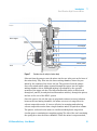
Mixers are dual chamber high pressure dynamic mixers designed for binary
and ternary gradient HPLC and preparative HPLC systems, see Figure 7 on
page 21.
The unique design of the mixer employs a motor-driven magnet oriented
perpendicular to the mixing chambers. As the magnet turns, it causes two
magnetic stir bars inside the chambers to rotate by radial drive rather than by
axial drive as in other dynamic mixers. The close proximity of both stir bars to
the rotating drive magnet and the fact that the stir bars rotate in opposite
directions ensures continuous and thorough mixing.
A unique piston-type closure on the outlet of the mixer allows easy
disassembly without tools for cleaning and maintenance. On analytical and
narrowbore mixers the piston incorporates a 2 μm solvent filter to protect
system components from contamination.
The mixer is designed to be plumbed into an HPLC system between the pumps
and the injection valve.
Titanium and PEEK mixers are available for applications where 316 stainless
steel may be inappropriate because of corrosion or release of metal ions into
solution. Titanium or PEEK plumbing components can be used together with
PEEK tubing to provide a totally iron-free fluid path.
20
218 Solvent Delivery - User Manual
1
Introduction
Dual Chamber High Pressure Mixer
&%"(';^ii^c\ZmigVadc\
E^hidc
B^mZgXVe
9g^kZbV\cZi
HZVa
HZVagZiV^cZg
;g^i
Hi^gWVgjeeZg
HeVXZg
Hi^gWVgadlZg
H]V[i
&%"(';^ii^c\hiVcYVgY!':6
Figure 7
Section view of analytical mixer body
Solvents from the pumps enter the mixer via the two inlet ports at the base of
the mixer body. They flow into the lower mixing chamber, where they are
mixed by the rotation of the lower stir bar. The pressure from the pumps
forces the mixed mobile phase upward through the spacer into the upper
mixing chamber, where additional mixing is performed by the opposite
rotation of the upper stir bar. The fully mixed mobile phase is then forced
through a 2 μm frit (in analytical and narrowbore mixers), through the piston,
and out to the rest of the HPLC system.
Since the spacer (the stir bar cage on preparative mixers) assures isolation
between the two mixing chambers, the mixer acts as a two-stage filter for
solvent composition noise. It is more effective in averaging and reducing
solvent composition noise than a single-chamber mixer of equivalent volume.
The passive seal used in the mixer is a hollow molded plastic ring with a
circular groove containing an energizing spring. The side of the seal containing
the spring faces into the mixer chambers. When the mixer is unpressurized,
218 Solvent Delivery - User Manual
21
1
Introduction
Dual Chamber High Pressure Mixer
the small spring inside the seal maintains contact with the mixer bore and the
piston with enough force to seal at low pressures, but not excessive force to
prevent the seal from sliding as the mixer cap is hand-tightened. When
pressurized, mobile phase enters the mixer body and presses the seal against
the mixer bore and the piston. The increased force maintains sealing action at
HPLC pressures.
The inlet ports on the analytical and narrowbore mixers accept standard 10-32
fittings. The outlet port uses an extra-long 10-32 fitting. On the preparative
scale, both inlet and outlet ports accept 1/4-28 fittings for 0.318 cm (1/8 in)
tubing.
Effective sealing in the mixer is a function of the passive sealing mechanism
only. The sealing action cannot be improved by tightening the cap with more
force than can be applied by hand.
22
218 Solvent Delivery - User Manual
1
Introduction
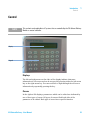
Control
Control
NOTE
This section is only applicable to LC systems that are controlled by the 218 Solvent Delivery
Module as master controller.
9^heaVn
@ZneVY
Displays
The left and right arrows at the sides of the display indicate that more
information is off screen and can be accessed by pressing either the left arrow
key or the right arrow key. You can scroll left or right through the off-screen
information by repeatedly pressing the key.
Cursors
In the Agilent 218 displays, parameters which can be edited are indicated by
one of four types of cursor. All types of cursors flash both sides of the
parameter to be edited. Each type of cursor has a specific function.
218 Solvent Delivery - User Manual
23
1
Introduction
Control
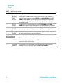
Table 1
Specific cursor functions
Cursor
Name
Function
--
NUMERIC
ENTRY
CURSOR
Used for numeric entry only. Values entered or edited while the cursor is flashing are
temporary until accepted by pressing the ENTER key, the RIGHT ARROW key, the LEFT
ARROW key, or the RUN key. If the edited value is not accepted by pressing one of the
above keys, or cancelled by pressing the CLEAR key, the parameter reverts to its previous
value after 60 seconds.
↓↑
SCROLL
CURSOR
Used when there is a preset list of choices. Pressing the UP ARROW or the DOWN
ARROW with this type of cursor is displayed scrolls up or down through the preset choices.
??
DUAL-MODE
CURSOR
Used when there is a preset list and numeric entry. Used when the value can be set either
by numeric entry or by scrolling through a preset list of choices, as described above.
||
MENU
CURSOR
Used when the selection is a menu. Pressing the DOWN ARROW or the ENTER key with
this type of cursor displays the next level of the menu.
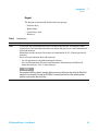
NOTE
The following are not cursors, but are described here for clarity.
*
ASTERISK
Used to show cursor position (for accessing HELP) when the parameter in question is a
status indicator and cannot be edited.
←→
LEFT-RIGHT
ARROWS
These indicators are used at the right or left edge of the display to indicate that more
information can be seen by pressing either the RIGHT or LEFT ARROW key.
24
218 Solvent Delivery - User Manual
Introduction
Control
1
Keypad
The keypad is functionally divided into four groups:
• Function keys,
• Method keys,
• Control keys, and
• Edit keys.
Table 2
Function keys
Key
Function
Flow
This key opens the FLOW window where you can set flow rate and ramp time. The window also shows
system pressure. The left and right arrows at the sides indicate that you can access more information with
the left-right arrow keys:
Method status and name to the left. Current values for composition for %B, %C, %D to the right. Also I/O
parameters.
You can reach more information to the right in two ways:
• Press the right arrow to scroll rightward through the entire line.
• Press the I/O button below. (The entire line of information is divided between the FLOW and I/O
buttons for convenience. “time” is always displayed.)
NOTE
Pressing the FLOW key when in another display returns the display to the part of the Flow field
which was last viewed. Pressing the FLOW key a second time returns to the default position,
with the cursor on the flow rate value.
218 Solvent Delivery - User Manual
25
1
Introduction
Control
Table 2
Function keys
Key
Function
I/O
This key opens the second part of the display. Note that you can scroll leftward into the Flow section if you
wish. The I/O section contains the following items, from left to right:
Analog
Analog Input. This is the current voltage read on the Analog input channel for this pump
only. Range from –0.5 V to +2.5 V.
ishtm
Input Contact Status. Contacts are: Inject, Stop, Hold, Transfer and Mark. “1” indicates a
closed contact, “0” indicates an open contact.
Meth
Method status and name (repeat information from Flow display above).
nm
This control is used to set wavelength on a suitable detector when the analog out signal
has been set to the “nm” option in Setup or there is a detector online. Range is 1.90 V
(190 nm) to 7.00 V (700 nm).
w
Inject Wait. When a method is running, this is used to set an inject wait. The method will
hold at current conditions until the wait is cancelled, when the method will continue. The
wait can be cancelled manually by pressing the RUN key or by contact closure on the Inject
input.
A
Alarm. Can be set to “1” (on), “0” (off), or “P” (Pulse on then off). If Pulsed, the alarm will
sound three times then off. If set to Pulse at the same time as an inject wait, the alarm
sounds four times, then off. Otherwise the alarm sounds continuously until turned off.
1 - 12
Output contacts. Can be set to “0” (off), “P” (Pulse on then off), “1” (on), or “P” (Pulse off
then on). Pulses last for 0.5 s. Contacts 1–3 are for Pump A or the Master Pump in a
multi-pump configuration.
The Master Pump can control the outputs as follows:
• Contacts 1, 2, 3 are for Pump A or the Master Pump.
• Contacts 4, 5, 6 are for Pump B.
• Contacts 7, 8, 9 are for Pump C.
• Contacts 10, 11, 12 are for Pump D.
One or two contacts can be dedicated for High and Low Pressure signals, defined in the
pressure window below. Pressure States are H for High, L for Low, or b for both, if the same
contact is used for high and low limits.
NOTE
Pressing the I/O key when in another display returns the display to the part of the
I/O field which was last viewed. Pressing the I/O key a second time returns to the
default position, with the cursor on “nm”.
26
218 Solvent Delivery - User Manual
Introduction
Control
Table 2
1
Function keys
Key
Function
PRESSURE
Opens the PRESSURE window containing several pressure-related items.
ZERO
The pressure can be zeroed using the up/down arrow key. Executing a Zero command
displays a prompt. When system pressure is more than 50 psi, a second prompt with
current pressure is displayed.
psi/bar/MP
a
Current system pressure is shown in the selected units.
MAX P
Maximum system pressure limit, in the units selected.
MIN P
Minimum system pressure limit, in the units selected.
UNITS
Select between psi, bar, and MPa (mega Pascals).
OUTPUT
CONTACTS
Set the output contacts to be used for MAX P and MIN P signals.
NOTE
The same contact can be set for both high limit and low limit.
218 Solvent Delivery - User Manual
27
1
Introduction
Control
Table 2
Function keys
Key
Function
SETUP
Opens the Set Up and Service Log menus. The Service Log is used to log piston seal changes, check valve
changes/service intervals, and show the pump drive status. See the Maintenance section for details of this
function. The Set Up menu appears in one of two forms, depending on whether the Agilent 218 is a master
controller or a slave pump. In both cases, Set Up is used to set up various parameters listed below:
As Slave Pump:
ID
Pump ID. Set the ID for the Agilent 218 either by entering a number between 0 and 63, or
pressing the UP ARROW or DOWN ARROW key to scroll through a preset list of choices.
Available choices are: 0–63, MC (master controller) or – – (no ID).
HdSz
Pump head size. Use the UP ARROW or DOWN ARROW to select between a preset list of
choices. Choices are: 5, 10, 25, 50, 100, and 200 (mL/min), 10P, 25P, 50P, 100P. The “P”
designation stands for PEEK. The compressibility compensation for PEEK heads is different
than for stainless steel or titanium heads.
x
Compressibility Factor. This is used to calculate the flow rate compensation necessary to
correct for the solvent’s compressibility. Values can be set between 0 – 2000 Mbar-1.
Default of 46 is the setting for water. The parameter can be adjusted to set the measured
flow rate at exactly the set flow rate. See “Adjusting the Flow Rate on the Pump” on
page 81 for details on how to do this. Other solvents will have different x parameters. See
“Solvent Compressibility” on page 125 for a list of values for other solvents.
L
High Pressure Constant. Range is from 1 – 9999 bar. Default is 3231 bar, the value for
water. Consult the available literature for high pressure constants for other solvents. A
partial list is given in “Solvent Miscibility” on page 124.
REFILL
Refill time in milliseconds. Refill time is the time required for the piston return stroke.
Range is from 100 – 1000 ms.
CIM
Control-Interface Module ID. Set the ID for the CIM installed in the pump either by entering
a number between 0 and 63, or pressing the UP ARROW or DOWN ARROW key to scroll
through a preset list of choices. Can be set between 0 and 63, or to – – (no ID).
As Master Controller:
28
AOut
Analog Out. 0 – 10 V output signal with 8 options. Output can be sent to a detector (to
control wavelength) or to a recording device. Options are: Flow, nm (wavelength),
Pres(sure), %A, %B, %C, %D, or off.
PUMPS
Select between A, B, C, and D. Selecting a pump opens a window to set Pump ID, Head
size, compressibility factors, and refill speed.
Detr
Sets the ID number for any detector connected to the serial cable.
Bus Status
Shows the status of serial devices. The display shows ID numbers of devices and active
devices at any of the IDs. Identifiers are “B, C, D, or P” for Pump, “M” for Detector, “I” for
CIM, and “E” for Error.
BUS IDs
Identifies devices defined on the serial bus with their model number, ID number, and status
(online or offline) device IDs of some remote devices may be changed in this window.
218 Solvent Delivery - User Manual
Introduction
Control
Table 3
1
Method keys
Key
Function
METHOD
Displays method information. Pressing the METHOD key opens a window where you can see the status of
the running method and scroll through a list of existing methods. Method Status codes are:
V
View. Indicates that the method in the display is not running.
I
Initialization. The displayed method is ramping to time 0 (inject time).
R
Running. The displayed method is running (beyond time 0).
S
Stop. The displayed method is stopped, and flow rate = 0, by the STOP key or external
input, or by the method finishing with 0 mL/min flow rate.
H
Hold. The displayed method is holding. Either the HOLD key was pressed, an Inject Wait
programmed, or an external input was received.
F
Finished. The method has run and finished normally with flow rate ? 0.
For non-manual methods the Agilent 218 displays a list of method parameters, which can be accessed by
scrolling with the RIGHT ARROW and LEFT ARROW keys:
RECALL
Meth
This shows the Method name and status (see above).
PASS
Indicates the current method pass (if there are more than one).
#TIMES
Indicates the total number of times (up to 99) that the method will be executed before it
finishes.
Access
method will be executed before it finishes. Access User can scroll between LOCK and
UNLOCK. Locked methods cannot be edited. They are saved intact and when running
Locked methods ignore the HOLD key.
Transfer
Lets you set a method to be transferred to in one of three ways:
• immediately on receipt of a Transfer contact closure input
• at the end of the current method pass on receipt of a Transfer input
• automatically on completion of all the method passes
Safety
Allows you to assign a safety method for any of the following conditions:
• Stop input
• High Pressure Limit
• Low Pressure Limit
• Pump Off-line
Returns the pump to the current status timeline of the running method. The fields displayed in this view are
the same as were displayed the last time the FLOW or I/O key was pressed in the running method. When
on the current time line RECALL returns to the last display viewed.
218 Solvent Delivery - User Manual
29
1
Introduction
Control
Table 3
Method keys
Key
Function
HELP
Opens a Help display for the parameter which is selected. In most cases, the help information is longer than
will fit a two-line display.
• Scroll through the help message by pressing the HELP key, the RIGHT ARROW key, or the DOWN
ARROW key.
• Scroll back through the Help message by pressing the UP ARROW or the LEFT ARROW key.
• Press the CLEAR key or the HELP key at the end of the message to exit the Help.
L-R Arrows
These keys are used to move right and left in the display to access adjacent menus and to set values.
U-D Arrows
These keys are used to scroll up or down through preset values or toggle between choices. They are also
used to select time lines in a method. The Down Arrow key is also used to open menus.
ENTER
The Enter key is used to open menus. It also is used to accept a value.
Table 4
Control Keys
Key
Function
RUN
Starts the method timer and begins a linear ramp from current conditions to the target conditions at the
next time line in the method. If used to clear a Hold, (see below) RUN continues the run from the HOLD
point.
HOLD
Stops the method timer but does not change current flow or composition conditions. Holds the ramp at its
current position. This key is cancelled by pressing RUN again or STOP.
PRIME
Runs the pump at the maximum flow rate for the installed pump head. Pressing STOP stops the pump when
it is priming. All other keys are locked out from operation while the pump is priming.
STOP
Stops flow immediately and aborts the Run method.
Table 5
Edit keys
Key
Function
0–9, and .
Numeric keys, used to enter numeric values into parameters: method number, flow rate, minimum and
maximum pressure limits, pump ID, CIM ID, etc.
CLEAR
Used to cancel a user-entered value or choice, leaving the previously entered setting intact. Also used
when zeroing pressure, answers "No" to prompts and clears messages.
U-D Arrows
Used to scroll through a list of options and select an item from the list.
ENTER
Accepts a temporary value into a parameter. Answers "Yes" to prompts.
30
218 Solvent Delivery - User Manual
218 Solvent Delivery - User Manual
2
Site Requirements and Specifications
Site Requirements
32
Physical Specifications
35
Performance Specifications
36
This chapter provides information on environmental requirements, physical and
performance specifications.
Agilent Technologies
31
2
Site Requirements and Specifications
Site Requirements
Site Requirements
Power Considerations
The instrument power supply has wide ranging capability. It accepts any line
voltage in the range described in Physical Specifications.
WA R N I N G
Hazard of electrical shock or damage of your instrumentation
can result, if the devices are connected to a line voltage higher than specified.
➔ Connect your instrument to the specified line voltage only.
CAUTION
Inaccessible power plug.
In case of emergency it must be possible to disconnect the instrument from the power
line at any time.
➔ Make sure the power connector of the instrument can be easily reached and
unplugged.
➔ Provide sufficient space behind the power socket of the instrument to unplug the
cable.
32
218 Solvent Delivery - User Manual
2
Site Requirements and Specifications
Site Requirements
Power Cords
Different power cords are offered as options with the module. The female end
of all power cords is identical. It plugs into the power-input socket at the rear.
The male end of each power cord is different and designed to match the wall
socket of a particular country or region.
WA R N I N G
Absence of ground connection or use of unspecified power cord
The absence of ground connection or the use of unspecified power cord can lead to
electric shock or short circuit.
➔ Never operate your instrumentation from a power outlet that has no ground
connection.
➔ Never use a power cord other than the Agilent Technologies power cord designed
for your region.
WA R N I N G
Use of unsupplied cables
Using cables not supplied by Agilent Technologies can lead to damage of the
electronic components or personal injury.
➔ Never use cables other than the ones supplied by Agilent Technologies to ensure
proper functionality and compliance with safety or EMC regulations.
WA R N I N G
Unintended use of supplied power cords
Using power cords for unintended purposes can lead to personal injury or damage of
electronic equipment.
➔ Never use the power cords that Agilent Technologies supplies with this instrument
for any other equipment.
218 Solvent Delivery - User Manual
33
2
Site Requirements and Specifications
Site Requirements
Bench Space
The module dimensions and weight (see Table 6 on page 35) allow you to place
the module on almost any desk or laboratory bench.
It needs an additional 5 cm (2 in) of space on either side and approximately
15 cm (5.9 in) at the rear for air circulation and electric connections.
If the bench shall carry a complete HPLC system, make sure that the bench is
designed to bear the weight of all modules.
The module should be operated in a horizontal position.
Condensation
CAUTION
Condensation within the module
Condensation will damage the system electronics.
➔ Do not store, ship or use your module under conditions where temperature
fluctuations could cause condensation within the module.
➔ If your module was shipped in cold weather, leave it in its box and allow it to warm
slowly to room temperature to avoid condensation.
34
218 Solvent Delivery - User Manual
Site Requirements and Specifications
Physical Specifications
2
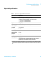
Physical Specifications
Table 6
Specifications Agilent 218 Purification Solution
Type
Specification
Rated voltage
100 – 240 VAC (90 – 264 Absolute), 50 – 60 Hz
The Agilent 218 Purification Solution1 may be wired for either:
• 115 V ±10 % , 50 /60 Hz single phase
• 230 V ±10 % , 50 /60 Hz single-phase
Weight
23.6 kg(52.0 lb)
Dimensions (height x
width x depth)
197 x 292 x 464 mm (7.8 x 11.5 x 18.3 in)
Line voltage
115 – 230 V ±10 %
Line frequency
50 – 60 Hz
Power consumption
550 VA
Ambient operating
temperature
3 – 40 °C
Humidity
20 – 80 %
Operating altitude
up to 2000 m
The 218 System Pump is suitable for indoor use only and is classified
Pollution degree 2 and Installation Category II (EN 61010-1).
1
All power supplies should be single phase AC, 3 wire system (active, neutral, ground) and should
be terminated at an appropriate connection receptacle that is within reach of the system power cable.
218 Solvent Delivery - User Manual
35
2
Site Requirements and Specifications
Performance Specifications
Performance Specifications
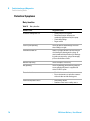
Table 7
36
Performance specifications Agilent 218 Purification Solution
Type
Specification
Display
Backlit LCD with 2 lines, 48 characters
Programs
Up to 100 methods with unlimited timed events
Interface
•
•
•
•
•
Flow Accuracy
1 % of selected flow rate or 0.05 % of maximum flow, whichever is larger
(0.1 % for 5 mL/min heads)
Flow Reproducibility
0.1 % of selected flow or 0.05 % of maximum flow, whichever is larger
(0.01 % for 5 mL/min heads)
Connections
•
•
Fluid Path
316 stainless steel, titanium, sapphire or ceramic, ruby, PCTFE, PTFE, or
HDPE
Digital serial input/output channel (RS-422)
3 programmable contact-closure relay outputs
5 contact-closure inputs
1 analog input (-0.5 V to +2.5 V), 18-bit A/D converter
1 programmable analog output (0 – 10 V )
1/4-28 inlet flanged or gripper-type fitting
1/4-28 outlet for nut and ferrule
218 Solvent Delivery - User Manual
Site Requirements and Specifications
Performance Specifications
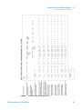
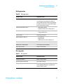
Table 8
2
Pressure limits pump heads
Nominal flow
(mL/min)
Range
(mL/min)
SST and Titanium
(pressure
maximum)
PEEK (pressure
maximum)
10
0.01 – 10
8700 psi
600 bar
60.0 MPa
4000 psi
275 bar
27.6 MPa
25
0.025 – 25
6000 psi
414 bar
41.4 MPa
4000 psi
275 bar
27.6 MPa
100
0.1 – 100
4000 psi
275 bar
27.6 MPa
2000 psi
137 bar
13.8 MPa
200
0.2 – 200
3500 psi
241 bar
24.1 MPa
N/A
218 Solvent Delivery - User Manual
37
2
Site Requirements and Specifications
Performance Specifications
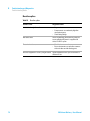
Table 9
Description/wetted
materials
Inlet fittings
(in)
Outlet fittings
(in)
Max.
pressure
(psi)
Max. flow
rate (mL/min)
10 mL/min , Titanium, FEP
¼-28
¼-28
8700
10
50 mL/min , Titanium, FEP
¼-28
¼-28
6000
50
100 mL/min , Titanium, FEP
¼-28
¼-28
1200
100
10 mL/min , PEEK, FEP
¼-28
¼-28
4000
10
50 mL/min , PEEK, FEP
¼-28
¼-28
4000
50
100 mL/min , PEEK, FEP
¼-28
¼-28
2000
100
200 mL/min , Titanium, FEP
¼-28
¼-28
400
200 1
1
38
Performance specifications pressure modules
Uses 0.318 cm (1/8 in.) ID tubing.
218 Solvent Delivery - User Manual
218 Solvent Delivery - User Manual
3
Installation
Installation
40
This chapter gives information about the installation of your instrument.
Agilent Technologies
39
3
Installation
Installation
Installation
For details on installation of the module, refer to Agilent 218 Purification
System – Setup and Installation Guide (G9300-90301).
40
218 Solvent Delivery - User Manual
218 Solvent Delivery - User Manual
4
Using the 218 Solvent Delivery Module
Introduction
Power On
42
43
Priming the Pump Heads
44
Creating a Simple Method on an Agilent 218 Pump
Check and Run the Method
Method Menu
Sample Methods
45
46
48
54
This chapter explains the operational parameters of the instrument.
Agilent Technologies
41
4
Using the 218 Solvent Delivery Module
Introduction
Introduction
The Agilent 218 Purification Solution can be used in several different modes of
operation, including operation as a master pump in an automated HPLC
system. This section explain how to use the LC system if the 218 pump is
configured as master controller. If your LC system is controlled by OpenLAB
CDS ChemStation as master controller, please refer to the OpenLAB CDS
online help system.
NOTE
42
If the equipment is used in a manner not specified by the manufacturer, the protection
provided by the equipment may be impaired.
218 Solvent Delivery - User Manual
Using the 218 Solvent Delivery Module
Power On
4
Power On
1 Press the power switch on the module.
The Agilent 218 pump will perform a self-check and display the screens
below in the order shown.
Appropriate pressure rating will be shown.
218 Solvent Delivery - User Manual
43
4
Using the 218 Solvent Delivery Module
Priming the Pump Heads
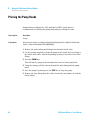
Priming the Pump Heads
Pump heads are shipped dry. IPA, methanol or HPLC grade water is
recommended for priming the pump heads and pre-wetting the seals.
Tools required
Description
Syringe
Preparations
Pump head size entered, see Setting the Pump ID and Pump Head Size in Agilent 218 Purification
System – Setup and Installation Guide (G9300-90301).
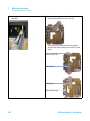
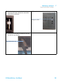
1 Remove the outlet tubing and fitting from the outlet check valve.
2 Use the syringe supplied to prime the pump head. Attach the Luer fitting to
the outlet check valve. Attach the priming syringe to the outlet of the Luer
fitting.
3 Press the PRIME key.
This will run the pump at the maximum flow rate for that pump head.
4 Using the syringe, pull the solvent through the inlet tubing and the pump
head.
5 Once the pump is primed, press the STOP key to stop the pump.
6 Remove the Luer fitting from the outlet check valve and replace it with the
outlet tubing.
44
218 Solvent Delivery - User Manual
4
Using the 218 Solvent Delivery Module
Creating a Simple Method on an Agilent 218 Pump
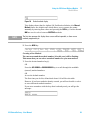
Creating a Simple Method on an Agilent 218 Pump
The following method will ramp an Agilent 218 Pump to 5 mL/min in 2
minutes to time 0.00. At time 0.00, the pump will wait for inject and Alarm;
make the injection, and maintain flow rate at 5 mL/min for 5 minutes. After 5
minutes, the flow rate will ramp to 0 mL/min over 5 minutes. Use a pump head
size of 10 mL or greater for this method.
1 Press the METHOD key.
2 Press the NEW key (a new method number will be selected and displayed
automatically). The method number displayed will be the next available
number from 0 to 99.
3 Press the FLOW key.
4 The starting time is shown in minutes (default is -2.00). If this is not
displayed, press 2, ENTER. This is the time for the linear ramp to initial
conditions.
5 Press the DOWN ARROW key to get to time 0.00.
6 Press the RIGHT ARROW key to move to the FLOW field. Press 5 (flow rate of
5 mL/min.)
7 Press the I/O key then the RIGHT ARROW key to get to the w field. Press the
UP ARROW key with the cursor on the w field. The value changes to 1 (ON).
8 Press the RIGHT ARROW key to get to the A field. Press the DOWN ARROW key.
The value changes to P (Pulse on then off).
9 Press the FLOW key then the LEFT ARROW key to get to the Time field.
10 Press the NEW key.
11 Press 5 to set a time of 5 minutes.
12 Press the RIGHT ARROW to get to the FLOW field and press 5.
13 Press the NEW key and then press 1, 0, then ENTER.
14 Press the RIGHT ARROW key and then 0, ENTER.
218 Solvent Delivery - User Manual
45
4
Using the 218 Solvent Delivery Module
Check and Run the Method
Check and Run the Method
1 Press the LEFT ARROW key until you are at the Time field then press the UP
ARROW key a number of times to read through the method time lines.
2 Press the DOWN ARROW key to scroll down through the time lines.
3 Press the RUN key to begin this method.
You will see the time field counting down and the flow rate counting up, to
reach 5 mL/min at time zero. Then you will hear the alarm at time 0,
indicating there is an inject wait.
NOTE
If you were performing an actual run, the inject wait would be cancelled by a contact
closure from either the manual injection valve or an autosampler. In this case, cancel it as
follows:
• Press the RUN key to clear the HOLD. This will act as an injection signal in this
demonstration method.
The method will continue to run its course, ramping from 0 to 5 mL/min over
2 minutes, and then maintaining 5 mL/min until 5 minutes, finally ramping
down to zero flow rate at 10 minutes.
46
218 Solvent Delivery - User Manual
Using the 218 Solvent Delivery Module
Check and Run the Method
Figure 8
4
Method editing: diagrammatic form
218 Solvent Delivery - User Manual
47
4
Using the 218 Solvent Delivery Module
Method Menu
Method Menu
Display the Main Method display
1 Press the METHOD key then the NEW key.
The Main Method display is visible.
Figure 9
Main Method display
NOTE
You will not see all this information at once, but can access the off-screen portion of the
display with the RIGHT ARROW key. The DOWN ARROW is used to select menu choices,
such as ACCESS: its choices are UNLOCK and LOCK.
NOTE
The TRANSFER and SAFETY method sub-menus are also shown. These sub-menus are
used to specify which method is to be used when there is a Transfer or Stop signal received
by the pump and are also opened by pressing the DOWN ARROW key.
NOTE
The New status and COPY OF Meth appear only when you press the New key. Once a
method is created, these items do not appear in the display.
Preparing Creating a Method
1 Press the METHOD Key
The default method display is open.
48
218 Solvent Delivery - User Manual
Using the 218 Solvent Delivery Module
Method Menu
Figure 10
4
Default method display
This display shows that the Agilent 218 Purification Solution is in Manual
Method status, the default state which allows you to operate the pump
manually by entering flow values and pressing the RUN key. Cursors around
MM are used to select between EXISTING methods.
NOTE
The first time you open this display these cursors will be inoperable, as there are no
methods programmed yet.
2 Press the NEW key.
Creating a New Method
The cursors around the method number (0 in this case) will be flashing.
This means that you can select a method number for your new method.
1 Press the desired number key(s).
OR
Press the UP ARROW or DOWN ARROW key to scroll through the available
(unused) method numbers.
OR
Access the default number.
The first time you do this, all methods from 0–99 will be selectable.
However, if you have methods already created, you will not be able to select
or enter allocated method numbers.
If you enter a number with the keys that is already used, you will get the
message:
218 Solvent Delivery - User Manual
49
4
Using the 218 Solvent Delivery Module
Method Menu
NOTE
You can create up to 99 methods. This may seem like overkill, but is useful when there are
multiple users in a lab: Specialized methods, such as Transfer methods or Safety methods,
could be allocated from 90–99.
Examples on how to use this feature:
• Analyst A could use methods from 20–29, and Analyst B from 40–49.
• Specialized methods, such as Transfer methods or Safety methods, could be allocated
from 90–99.
Copying Methods
The Agilent 218 Purification Solution allows you to duplicate an existing
method. This is useful if you want to create a new method with the same or
similar conditions as an existing method. Perhaps you wish to change only a
single parameter or condition.
1 Press the RIGHT ARROW key to reach the COPY OF Meth field and then use the
UP ARROW or DOWN ARROW to scroll through a list of existing method
numbers.
OR
If you already know the method you wish to duplicate, enter the number
with the number keys.
Display PASS
This is not editable, but is a display of the current pass (if more than one)
of the method.
1 See #TIMES, step 1 on page 50.
Set #TIMES
1 Use the LEFT ARROW or RIGHT ARROW key to move to the #TIMES field.
2 Enter the number of times you wish the method to execute before stopping.
When the method is running, the PASS field will increment for each time the
method executes.
Set the ACCESS level
This field lets you set the access level, or status of the method.
1 Use the LEFT ARROW or RIGHT ARROW key to move to the ACCESS field.
2 Choose between UNLOCK and LOCK.
50
218 Solvent Delivery - User Manual
4
Using the 218 Solvent Delivery Module
Method Menu
NOTE
Unlocked methods can be edited and changed, even while running. Locked methods cannot
be edited and the steps are protected from change. The Hold key will be ignored when a
Locked method is running.
Assign a TRANSFER Method
1 Use the LEFT ARROW or RIGHT ARROW key to move to the TRANSFER Meth
field.
2 Press the DOWN ARROW.
Figure 11
Sub-Menu to set transfer method
3 Set the method to be transferred in the event of a TRANSFER signal to the
Agilent 218 or automatically at the end of the method if no transfer signal is
received.
NOTE
If you do not wish the method to transfer, leave this entry blank.
4 Use the UP ARROW or DOWN ARROW key to scroll between existing method
numbers.
OR
Enter the method number with the number keys.
5 Under the MODE field, use the UP ARROW or DOWN ARROW key to select
between IMMED(iate) or DEFER(ed).
NOTE
• If you choose IMMED, the transfer function will occur immediately on receipt of the
transfer contact closure.
• If you choose DEFER, the transfer will take place at the end of the current method pass
IF a transfer contact closure is received.
• If there is no transfer contact closure received, the method will transfer automatically at
the end of all method passes.
218 Solvent Delivery - User Manual
51
4
Using the 218 Solvent Delivery Module
Method Menu
6 Press the Method key to leave this sub-menu and return to the Method
Menu.
Assign a SAFETY Meth
Set the method to be transferred to in the event of an emergency condition
or contact closure to the Agilent 218 Purification Solution.
1 Use the LEFT ARROW or RIGHT ARROW key to move the cursor on SAFETY
METH.
2 Press the DOWN ARROW key.
3 Select between the available methods for each field with the UP ARROW or
DOWN ARROW key.
OR
Enter the method number with the number keys.
Table 10
52
Safety methods
Setting
Use case
STOP
Used to set the method to be used in the event of a STOP signal to the
Agilent 218 Purification Solution. The current method will stop and
transfer to the selected method. If there is no STOP method selected the
pump will abort the running method and stop.
HIGH P
Used to set the method to be used in the event of a High Pressure
condition (High Pressure Limit, or Max Pressure, is set in the Pressure
menu). The current method will stop and transfer to the selected method.
If there is no HIGH P method selected the pump will transfer to the Stop
Safety method, if one is specified, otherwise it will simply stop when the
High Pressure Limit is reached.
218 Solvent Delivery - User Manual
4
Using the 218 Solvent Delivery Module
Method Menu
Table 10
NOTE
Safety methods
Setting
Use case
LOW P
Used to set the method to be used in the event of a Low Pressure
condition (Low Pressure Limit, or Min Pressure, is set in the Pressure
menu). The current method will stop and transfer to the selected method.
If there is no LOW P method selected the pump will transfer to the Stop
Safety method, if one is specified, otherwise it will simply stop when the
Low Pressure Limit is reached.
OFF-LINE
Used to set the method to be used in the event that one of the other pumps
in the system goes OFF-LINE. The current method will stop and transfer to
the selected method. If there is no method selected the Agilent 218 will
transfer to the Stop Safety method, if one is specified, otherwise it will
simply stop if another pump goes OFF-LINE.
If you do not wish the method to transfer, leave this entry blank.
4 Press the Method key to leave this sub-menu and return to the Method
Menu.
Assign a MODE
In NORMAL mode the master pump will operate normally and respond to
pressure, flow and compositional information from the other pumps in the
HPLC system. DEMO mode is useful for method development. This mode
allows you to create and run methods which control other pumps, without
those pumps being physically present. Also, a single-pump demo method
can be run without the pump operating; the display will indicate the
changing conditions, current time, flow rate, etc., but the drive mechanism
will not engage.
1 Use the LEFT ARROW or RIGHT ARROW key to move to the MODE field.
2 Select between NORMAL or DEMO.
218 Solvent Delivery - User Manual
53
4
Using the 218 Solvent Delivery Module
Sample Methods
Sample Methods
The following pages contain sample methods and a blank method sheet.
54
218 Solvent Delivery - User Manual
Using the 218 Solvent Delivery Module
Sample Methods
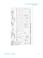
Figure 12
4
Proteins on C8
218 Solvent Delivery - User Manual
55
4
Using the 218 Solvent Delivery Module
Sample Methods
Figure 13
56
Aromatic hydrocarbons
218 Solvent Delivery - User Manual
Using the 218 Solvent Delivery Module
Sample Methods
Figure 14
4
AA Analytics
218 Solvent Delivery - User Manual
57
4
Using the 218 Solvent Delivery Module
Sample Methods
Figure 15
58
Standby
218 Solvent Delivery - User Manual
Using the 218 Solvent Delivery Module
Sample Methods
Figure 16
4
Stop
218 Solvent Delivery - User Manual
59
4
Using the 218 Solvent Delivery Module
Sample Methods
Figure 17
60
Blank
218 Solvent Delivery - User Manual
218 Solvent Delivery - User Manual
5
Optimizing Performance
Choose the Appropriate Pump Head for the Application
62
This chapter gives hints on how to optimize the performance or use additional
devices.
Agilent Technologies
61
5
Optimizing Performance
Choose the Appropriate Pump Head for the Application
Choose the Appropriate Pump Head for the Application
Choose from standard pump heads providing flow rates up to 10, 25, 100, or
200 mL/min.
Single Pump Operation
Ideally, for single pump operation, the flow rate should be between 5 % and
90 % of the maximum pump head flow rate.
Examples:
• 10 mL/min pump head for applications requiring between 0.5 – 9 mL/min
• 100 mL/min pump head should be used for applications requiring between
5 – 90 mL/min
NOTE
The pump head can be used at its fully specified range but a 10 mL/min pump head will
operate at 1 mL/min better than a 100 mL/min pump head.
Gradient Applications
Choosing the best pump heads for gradient applications is slightly different.
If possible, choose the pump head so that the system operates at or above 10 %
of the minimum pump head flow rate. Also try to use the smallest pump head
possible for gradient operation.
Protein Purification Applications
Biocompatible pump heads constructed entirely of titanium or chemically
inert plastics are available.
These heads incorporate a second chamber located behind the high-pressure
seal. This chamber, filled with water, literally washes the piston with each
stroke. This prevents scale build-up on the piston that can lead to premature
seal failure.
62
218 Solvent Delivery - User Manual
218 Solvent Delivery - User Manual
6
Troubleshooting and Diagnostics
Introduction to Troubleshooting and Diagnostics
Using the Pressure Display as Diagnostic Tool
Troubleshooting Guide
64
65
66
This chapter gives an overview about the troubleshooting and diagnostic
features.
Agilent Technologies
63
6
Troubleshooting and Diagnostics
Introduction to Troubleshooting and Diagnostics
Introduction to Troubleshooting and Diagnostics
Troubleshooting an HPLC system requires a methodical approach to be
effective.
To correct a given problem, proceed step-by-step, eliminating each variable in
turn before moving to the next. Some problems have more than one cause, and
can be difficult to locate and correct. The troubleshooting guide lists some
common pump and HPLC system symptoms, with possible causes and
suggested corrective actions.
In most cases, you will be able to correct the problem. However, sometimes the
symptom will remain after you have tried the corrective action. In these cases,
please contact your local Agilent office.
64
218 Solvent Delivery - User Manual
Troubleshooting and Diagnostics
Using the Pressure Display as Diagnostic Tool
6
Using the Pressure Display as Diagnostic Tool
The sensitivity of the pressure display is within 68.9 kPa (10 psi). The
pressure display can be used as a diagnostic tool. Following issues cause
characteristic pressure fluctuations in HPLC systems (parameters valid for
HPLC operating at normal pressure):
• Zero to several hundred kPa: Bubbles in the solvent
• 68.9 – 275.8 kPa Sticking check valve
HINT
If fluctuations > 68.9 kPa try to eliminate bubbles in the solvent (see “Clearing Air Bubbles
from the Liquid Head” on page 82).
If this does not solve the problem, a check valve is probably sticking. It may be possible to
rectify this problem by cleaning the check valve (see “Cleaning Check Valves” on page 94).
218 Solvent Delivery - User Manual
65
6
Troubleshooting and Diagnostics
Troubleshooting Guide
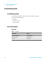
Troubleshooting Guide
Troubleshooting Guide
The troubleshooting guide is divided into sections, related to symptoms
observed in the following units:
• Electronics
• Liquid flow system
• Detector signals
Electrical Symptoms
Pump Dead
Table 11
66
Pump dead
Probable cause
Solution
Power cord disconnected
Plug in power cord
Power switched off
Switch power on
Fuse dead
Replace fuse
218 Solvent Delivery - User Manual
Troubleshooting and Diagnostics
Troubleshooting Guide
6
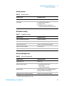
External Symptoms of Liquid Flow System
Leaks
Table 12
Leaks
Probable cause
Suggested actions
Loose fitting(s)
Tighten all plumbing connections no more than
1/4 turn past finger-tight.
Worn ferrule or fitting
Replace fitting and ferrule.
Damaged seal
Replace seal.
Loose check valve
Tighten 1/16 turn past the leak-point.
Incorrect fitting(s)
Reconnect with correct fittings.
No flow or pressure
Table 13
No flow or pressure
Probable cause
Suggested actions
Pump is not operating
1 Plug in power cord
2 Switch pump on
3 Check fuses and replace if necessary
Air in pump
1 Disconnect outlet fittings
2 Degas solvent.
3 Divert flow to waste and pump at a high
flow rate to prime pump.
Clogged solvent inlet filter
218 Solvent Delivery - User Manual
Check and replace if necessary.
67
6
Troubleshooting and Diagnostics
Troubleshooting Guide
Low flow
Table 14
Low flow
Probable cause
Suggested actions
Pump is pressure limiting
Reset MIN P setting to higher value.
Clogged solvent inlet filter
Check and replace if necessary.
Drain valve leaking
Repair leak in drain valve.
Excessive pressure, restricted flow
Table 15
68
Excessive pressure, restricted flow
Probable cause
Suggested actions
Tubing clogged/ partly clogged
Crack all fittings one by one until the pressure
reverts to normal. Then replace the section of
tubing immediately after the last cracked fitting.
Injection valve clogged
Flush injection valve, replace sample loop. If
this does not clear the blockage see the
injection valve manual.
Injector between LOAD/INJECT
Reposition to LOAD or INJECT.
Frit (filter) in column clogged
Replace the column frit.
Detector flow cell clogged
Attach a syringe to the flow cell inlet and try to
clear blockage by drawing on the syringe. Or
attach to outlet and back-flush to clear blockage
by gentle pressure on the syringe. Do not apply
pressure to the flow cell inlet.
218 Solvent Delivery - User Manual
Troubleshooting and Diagnostics
Troubleshooting Guide
6
Erratic pressure
Table 16
Erratic pressure
Probable cause
Suggested actions
Leak
Check and repair leaks.
Air in pump
1 Disconnect outlet fittings.
2 Degas solvent.
3 Divert flow to waste and pump at a
moderately high flow rate to prime pump.
Air bubble in tubing
Table 17
Air bubble in tubing
Probable cause
Suggested actions
Loose inlet tubing connection
Tighten inlet fittings.
Worn flange in inlet tubing
Remake inlet tubing flange.
Loose inlet check valve
Tighten 1/16 turn past the leak-point.
Inlet filter partially clogged
Clean or replace.
Loose outlet tubing connection
Tighten outlet fittings.
Excessive backpressure
Table 18
Excessive backpressure
Probable cause
Suggested actions
Clogged mixer frit
Replace frit1
Stir bar/spacer sticking
•
•
•
Blocked tubing
Loosen fitting after each component to find
blockage. Replace affected tubing.
Damaged ferrule in compression fitting
Replace ferrule. Do not over-tighten.
1
Dismantle and clean mixer
Filter solvents
Check solvent miscibility
Analytical and narrowbore mixers only.
218 Solvent Delivery - User Manual
69
6
Troubleshooting and Diagnostics
Troubleshooting Guide
Detection Symptoms
Noisy baseline
Table 19
Noisy baseline
Probable cause
Suggested actions
Air bubbles through flow cell
•
•
•
•
70
Install backpressure regulator
Divert flow to waste and pump at a
moderately high flow rate to prime pump
Check tubing fittings
Degas solvent
Leak in system plumbing
Check for deposits around fittings and check
that all fittings are tight.
Contaminated flow cell
Attach a syringe to the flow cell inlet and try to
clear blockage by drawing on the syringe. Or
attach to outlet and back-flush to clear blockage
by gentle pressure on the syringe. Do not apply
pressure to the flow cell inlet.
Detector lamp failing
Check and replace if necessary.
Bad grounding
Check all grounding connections on pump and
ensure grounded AC power is supplied to all
devices in HPLC system.
Electronic interference
•
•
Check for loose connections
Ensure instruments are not in direct contact
with each other or with vibrating parts
Localized temperature effects
•
•
Wrap tubing, column
Remove or cover heat or cooling source
218 Solvent Delivery - User Manual
6
Troubleshooting and Diagnostics
Troubleshooting Guide
Drifting baseline
Table 20
Drifting baseline
Probable cause
Suggested actions
Contaminated flow cell
Attach a syringe to the flow cell inlet and try to
clear blockage by drawing on the syringe. Or
attach to outlet and back-flush to clear blockage
by gentle pressure on the syringe. Do not apply
pressure to the flow cell inlet.
Localized temperature effects
•
•
Wrap tubing, column
Remove or cover heat or cooling source
Contamination in column
•
•
Wash or replace column
Change mobile phase
Leak in system
Locate leak and repair.
Bubble trapped in flow cell
•
•
•
Column not equilibrated
Flush system until column is equilibrated.
Mobile phase contamination
Use fresh HPLC-grade solvents.
Weak detector lamp
Replace detector lamp.
Flush flow cell
Degas solvent
Add back-pressure device to flow cell
Flat-top peaks
Table 21
Flat-top peaks
Probable cause
Suggested actions
Saturated electronics
Reduce sample volume.
Recorder adjusted incorrectly
Set recorder correctly.
Bad grounding
Check all grounding connections on pump and
ensure grounded AC power is supplied to all
devices in HPLC system.
218 Solvent Delivery - User Manual
71
6
Troubleshooting and Diagnostics
Troubleshooting Guide
Baseline spikes
Table 22
Baseline spikes
Probable cause
Suggested actions
Air bubbles through flow cell
•
•
•
72
Degas solvent
Pump to waste at a moderately high flow
rate to prime pump
Check tubing fittings
Bad connections
Check all grounding connections on pump and
ensure grounded AC power is supplied to all
devices in HPLC system.
Electronic interference
•
•
Electrical equipment in circuit cycling on and off
Isolate equipment which cycles on and off to a
different circuit.
Check for loose connections.
Ensure instruments are not in direct contact
with each other or with vibrating parts.
218 Solvent Delivery - User Manual
218 Solvent Delivery - User Manual
7
Maintenance and Repair
Introduction to Maintenance
Warnings and Cautions
75
Maintenance Schedule
77
Service Logs
74
79
Adjusting the Flow Rate on the Pump
81
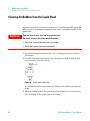
Clearing Air Bubbles from the Liquid Head
Removing Seals (Standard Head)
82
83
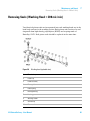
Removing Seals (Washing Head < 200 mL/min)
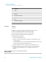
Removing seals 200 mL/min Head
85
87
Replacing Piston Seals (Heads < 200 mL/min)
88
Replacing Piston Seals (200 mL/min Head)
90
Breaking In a New Seal (200 mL/min Head)
92
Breaking In a New Seal (Heads < 200 mL/min)
Cleaning Check Valves
Replacing Check Valves
93
94
96
Checking and Replacing the Mixer Outlet Filter Frit (Analytical and
Narrowbore Mixers Only) 98
Replacing the Mixer Seal
99
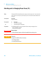
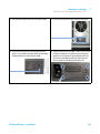
Checking and/or Changing Power Fuses (F1)
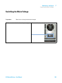
Switching the Mains Voltage
100
103
This chapter describes the maintenance of the instrument.
Agilent Technologies
73
7
Maintenance and Repair
Introduction to Maintenance
Introduction to Maintenance
The pumps have been carefully designed with continuous, unattended
operation in mind. Rugged construction and sophisticated electronics mean a
minimum of routine maintenance and years of trouble-free service if treated
carefully and if replacement parts are changed when they show signs of wear.
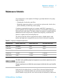
This section of the manual describes a maintenance schedule, service logs,
changing the piston seals, changing the check valve cartridges and changing
the mixer seals and frits.
You should take advantage of the Service Logs. Software in the pump
automatically tracks seal wear, check valve use, and pump drive wear. The
software also allows the user to enter and record seal and check valve
changes. Make it a point to check the Service Log area frequently and make
sure to record seal changes and check valve replacements into the software.
74
218 Solvent Delivery - User Manual
Maintenance and Repair
Warnings and Cautions
7
Warnings and Cautions
WA R N I N G
Toxic, flammable and hazardous solvents, samples and reagents
The handling of solvents, samples and reagents can hold health and safety risks.
➔ When working with these substances observe appropriate safety procedures (for
example by wearing goggles, safety gloves and protective clothing) as described in
the material handling and safety data sheet supplied by the vendor, and follow good
laboratory practice.
➔ The volume of substances should be reduced to the minimum required for the
analysis.
➔ Do not operate the instrument in an explosive atmosphere.
WA R N I N G
Electrical shock
Repair work at the module can lead to personal injuries, e.g. shock hazard, when the
cover is opened.
➔ Do not remove the cover of the module.
➔ Only certified persons are authorized to carry out repairs inside the module.
WA R N I N G
Personal injury or damage to the product
Agilent is not responsible for any damages caused, in whole or in part, by improper
use of the products, unauthorized alterations, adjustments or modifications to the
products, failure to comply with procedures in Agilent product user guides, or use of
the products in violation of applicable laws, rules or regulations.
➔ Use your Agilent products only in the manner described in the Agilent product user
guides.
218 Solvent Delivery - User Manual
75
7
Maintenance and Repair
Warnings and Cautions
CAUTION
Safety standards for external equipment
➔ If you connect external equipment to the instrument, make sure that you only use
accessory units tested and approved according to the safety standards appropriate
for the type of external equipment.
76
218 Solvent Delivery - User Manual
Maintenance and Repair
Maintenance Schedule
7
Maintenance Schedule
User maintenance on the Agilent 218 Pump is generally limited to the pump
head, as follows:
• Cleaning the check valves and filter.
• Replacing components subject to wear and tear: piston seals, check valves,
piston assembly, seal back-up, return spring.
Continuous, unattended operation is common with HPLC components. A
general guideline for the replacement frequency of consumable components is
indicated in the table below. The table assumes the pump is working at half its
maximum flow rate and pressure. Replacement frequency is indicated for
intensive, regular, and occasional pump use.
The solvent used also effects replacement frequency. Mobile phases with
buffers and high ionic strength will cause the seals to fail more frequently.
Table 23
Frequency of component replacement
Component/Use
Intensive (168 hrs/wk)
Regular (40 hrs/wk)
Occasional (10 hrs/wk)
Piston seal
4–6 months
1 year
2 years
Check valves
6–12 months
2 years
4 years
Piston assembly
1–2 years
4–6 years
8–10 years
Seal back-up
1–2 years
4–6 years
8–10 years
Return spring
2 years
4–6 years
8–10 years
NOTE
This table is only a guideline; pump head components may need to be replaced more or less
often than indicated.
Changes in performance, or visible leaks, give more precise indication that a part should be
replaced.
Seals need to be replaced every so often. This is because friction from the
moving pistons eventually abrades the seal and pressurized liquid in the
piston chamber seeps past the seal. Seal wear may be indicated by leaks from
218 Solvent Delivery - User Manual
77
7
Maintenance and Repair
Maintenance Schedule
the notch at the bottom of the liquid head, although this sign may not be
present if the solvent leak evaporates quickly.
Seal wear is accelerated under adverse conditions, such as pumping at high
flow rates or pressures, using aggressive or aqueous solutions, or dirty or
contaminated mobile phase. Moderate operation (low flow, low pressure,
organic solutions, and fresh clean HPLC-grade mobile phases) will result in
longer seal life. However, every seal will eventually need replacing. Software in
the Agilent 218 Pump allows you to both check the seal wear and to log when
the seals are changed. Your pump uses either a standard liquid head or a
washing liquid head.
78
218 Solvent Delivery - User Manual
Maintenance and Repair
Service Logs
7
Service Logs
Agilent 218 software automatically tracks seal wear, check valve use, and
pump drive wear. The software also allows the user to enter and record seal
and check valve changes.
Use the Service Logs
1 Press the SETUP key to open the SETUP / SERVICE log display.
2 Press the RIGHT ARROW to reach Service Log and then press the DOWN
ARROW to see the following display.
3 Select the desired menu by pressing the RIGHT or LEFT ARROW key.
Table 24
Piston Seal Log
Item
Function
SL LOG (Seal Log)
Displays the sequential number of last seal change.
DATE
Date of last seal change service. This value is entered numerically by the
user.
USE
Use units since last seal change, proportional to number of strokes and
pump pressure.
LIMIT
Use units limit set by user, depending on anticipated amount of use.
CHGD (Changed)
Press the DOWN ARROW then the ENTER key to enter YES when seal
change is performed.
Table 25
Check Valve Log
Item
Function
CK LOG
Sequential number of the last check valve service (check valve cartridge
replacement).
DATE
Date of last check valve service. This value is entered numerically by the
user.
218 Solvent Delivery - User Manual
79
7
Maintenance and Repair
Service Logs
Table 25
Check Valve Log
Item
Function
USE
Use units since last check valve service.
LIMIT
Use units set by user, depending on anticipated amount of use.
IO (Inlet/Outlet)
Press the UP or DOWN ARROW keys to scroll between the choices to
indicate the check valve. The check valve is referenced in the next menu
item (CHGD).
Scrollable choices are:
CHGD (Changed /
Serviced)
Table 26
80
IO
YY
Serviced both check valves
IO
NY
Serviced the outlet check valve, but
not the inlet check valve
IO
YN
Serviced the inlet check valve, but
not the outlet check valve
Press the DOWN ARROW then the ENTER key to enter YES when check
valve cartridge replacement (the only check valve user-service item) is
performed.
Pump drive
Item
Function
WEAR FACTOR
This indicates wear in the drive. Both the pump pressure and the flow rate
are recorded by the Agilent 218 software and factored into this indicator.
KCYLS
This is the number of piston strokes recorded by the pump software
divided by 1000.
HRS
Cumulative operational hours recorded by the pump software.
218 Solvent Delivery - User Manual
7
Maintenance and Repair
Adjusting the Flow Rate on the Pump
Adjusting the Flow Rate on the Pump
The flow rate can be adjusted using the compressibility compensation
parameters.
One may achieve this by applying pressure to the pump, using a column, a long
piece of small diameter analytical tubing or a restrictor valve.
When
Tools required
Operational qualification
Description
Restriction (column, small diameter tubing or restrictor valve)
Flow meter, volumetric flask or balance
1 Flush the system with water. (If you want to adjust the flow rate using a
different solvent, flush the system with that solvent.)
2 Enter the values for the compressibility compensation for water (or
whatever solvent you are using to adjust the flow rate). Using the SETUP key
and adjust the x value to
46 and the L value to
3231. (For a different solvent, use the compressibility values provided in
Table 29 on page 125.)
3 Put a restriction into the flow path that provides between 2000 psi
(13.8 MPa) and 3000 psi (20.7 MPa) pressure. This can be a column, a long
piece of small diameter tubing or a restrictor valve.
4 Set the flow rate to 1 mL/min (for the 5 or 10 mL pump heads) and
whatever flow is normally used for larger pump heads and start the pump.
Allow the pressure to come to equilibrium.
5 Measure the flow rate accurately using either a calibrated flow meter, a
calibrated volumetric flask or by weighing solvent on a calibrated balance.
6 If the measured flow rate is higher than the set flow rate, lower the value of
the x parameter. To raise the actual flow rate, increase the value of the x
parameter. For water, an increase or decrease of about 20 will lower the
flow rate about 0.5 % to 1 %. For other solvents, the x parameter adjustment
value will vary.
7 Continue to adjust the x parameter until the actual flow rate falls within
the pump specification of ±1 % of the set flow rate.
218 Solvent Delivery - User Manual
81
7
Maintenance and Repair
Clearing Air Bubbles from the Liquid Head
Clearing Air Bubbles from the Liquid Head
If you notice pressure fluctuations from zero to several hundred kPa when the
HPLC system is operating at normal pressure, there is probably a bubble in the
liquid head.
WA R N I N G
Chemical burns to eyes, skin, and/or respiratory tract
The mobile phases in the system may be hazardous.
➔ Observe all standard laboratory safety precautions.
➔ Always wear personal protective equipment.
1 Operate the pump at moderate flow (10 % of maximum) with the system
pressurized.
2 Carefully loosen the outlet check valve fitting; just enough to make it leak
(also known as crack the fitting).
Figure 18
Outlet check valve fitting
You should see solvent sputtering at the fitting as the bubble leaks past the
fitting.
3 When the bubble is clear, the sputtering will stop and the solvent will ooze
past the fitting. At this point tighten the fitting.
82
218 Solvent Delivery - User Manual
Maintenance and Repair
Removing Seals (Standard Head)
7
Removing Seals (Standard Head)
Figure 19
Standard pump head (exploded view)
1
Threaded cap
2
Piston cup
3
Piston assembly
4
Piston guide
5
Return spring
6
Screws
7
Bearing housing
218 Solvent Delivery - User Manual
83
7
Maintenance and Repair
Removing Seals (Standard Head)
Tools required
8
Housing spacer
9
Seal backup
10
Piston seal
11
Liquid head
12
Outlet check valve cartridge
13
Inlet check valve cartridge
14
Outlet check valve housing
15
Inlet valve housing
16
Outlet check valve cartridge
17
Inlet check valve cartridge
18
Outlet check valve housing
19
Inlet valve housing
Description
3 mm wrench
1 Make sure the pump is stopped and switch off the power switch.
2 Remove the fittings at the inlet and outlet check valves.
3 Loosen the head clamp nut and remove the head clamp.
4 Pull the pump head straight out from the pump body.
5 Disassemble the pump head:
a Unscrew the threaded cap (1).
b Remove the piston cup (2), piston assembly (3), piston guide (4), and
return spring (5).
c Loosen the two screws (6) at the front of the pump head. Remove the
bearing housing (7) and the housing spacer (8).
d Remove the seal backup (9).
6 Carefully remove the seal (10). If the seal is stuck, pry it out carefully so
that the liquid head (11) is not scratched.
NOTE
84
Do not reuse a seal after it has been removed.
218 Solvent Delivery - User Manual
Maintenance and Repair
Removing Seals (Washing Head < 200 mL/min)
7
Removing Seals (Washing Head < 200 mL/min)
Two identical piston seals are incorporated into each washing head: one in the
head body and one in the washing section. Each piston seal consists of a seal
ring made from high-density polyethylene (HDPE) and a spring made of
Hastelloy®-C276. Both piston seals should be replaced at the same time.
Figure 20
Washing head (exploded view)
1
Threaded cap
2
Piston cup
3
Piston assembly
4
Piston guide
5
Return spring
6
Bearing housing
7
Housing spacer
8
Washing section
9
Seal backup
10
Piston seal
218 Solvent Delivery - User Manual
85
7
Maintenance and Repair
Removing Seals (Washing Head < 200 mL/min)
Tools required
11
Liquid head
12
O-ring
13
Seal backup
14
Piston seal
15
Inlet check valve cartridge
16
Inlet check valve support screw
17
Screw
18
Outlet check valve cartridge
19
Outlet check valve support screw
Description
3 mm wrench
1 Make sure the pump is stopped and switch off the power switch.
2 Remove the fittings at the inlet and outlet check valves.
3 Loosen the head clamp nut and remove the head clamp.
4 Pull the pump head straight out from the pump body.
5 Disassemble the pump head:
a Unscrew the threaded cap (1).
b Remove the piston cup (2), piston assembly (3), piston guide (4), and
return spring (5).
c Loosen the two screws (17) at the front of the pump head and remove the
bearing housing (6) and the housing spacer (7).
d Remove washing section (8), o-ring (12), and seal backups (9, 13).
6 Carefully remove the seals (10, 14). If the seals are stuck, pry them out
carefully so that the liquid head (11) or washing section (8) is not
scratched.
NOTE
86
Do not reuse a seal after it has been removed.
218 Solvent Delivery - User Manual
Maintenance and Repair
Removing seals 200 mL/min Head
7
Removing seals 200 mL/min Head
Tools required
Description
1/4 in hex wrench
3 mm wrench
1 Turn off power to the pump.
2 Remove pump head clamp by loosening the hex screw
6 Place the liquid head with both inlet and outlet check
valves plugged.
with 1/4-in. hex wrench.
3 Lift off clamp and pull pump head out of the housing.
4 Unscrew the threaded cap (see Figure 19 on page 83) and
remove all parts possible from this side of the head.
5 Before loosening the two hex head screws draw a line
the length of the pump head body using a marker pen.
This line will make it easier to have all of the parts in the
correct orientation during reassembly. Loosen and
remove the two 3 mm hex head screws and separate all
of the parts.
7 Fill the cylinder cavity half full with HPLC-grade water.
Insert the ceramic piston into the cavity through the
piston seal.
8 Push down on the piston. The piston seal will pop out
onto the piston.
NOTE
When the seal pops out a small amount of water is
sprayed out, so use an area appropriate for this
procedure.
218 Solvent Delivery - User Manual
87
7
Maintenance and Repair
Replacing Piston Seals (Heads < 200 mL/min)
Replacing Piston Seals (Heads < 200 mL/min)
Preparations
The necessary seal tools come as part of the pump head kit.
Piston, seal, and seal location are clean, undamaged, and completely free from foreign matter.
1 Place the guide on the head or rinse body with the beveled side facing out.
2 Insert the new seal into the guide with spring down.
3 10 and 25 mL/min heads: Press the seal into place using the seal tool.
Figure 21
Seal replacement for 10 and 25 mL/min heads
OR
100 mL/min head: Press the seal into place using the seal tool.
Figure 22
88
Seal replacement for 100 mL/min heads
218 Solvent Delivery - User Manual
7
Maintenance and Repair
Replacing Piston Seals (Heads < 200 mL/min)
4 Reassemble the head by reversing the directions for seal removal, noting the
following:
• Align the ball housing assembly, the housing spacer, the rinse body (for
washing heads) and the head body so the matching hole or notch is on
the same side on each component.
• Thread the ball housing assembly, the housing spacer, and the rinse body
(for washing heads) to the head body. After these parts are attached, put
the assembly on a flat surface to facilitate mounting the other parts.
218 Solvent Delivery - User Manual
89
7
Maintenance and Repair
Replacing Piston Seals (200 mL/min Head)
Replacing Piston Seals (200 mL/min Head)
Preparations
The necessary seal tools come as part of the pump head kit.
Piston, seal, and seal location are clean, undamaged, and completely free from foreign matter.
1 Before installing a new piston seal make sure you are
installing the piston seal and not the washing section
seal.
2 Put the seal insertion tool (with protruding ring down)
into liquid head and make sure it is flush against the
liquid head.
E^hidchZVa
LVh]^c\hZXi^dchZVa
NOTE
The piston seal has ridges on its edge.
3 Place the piston seal (spring side down) in the seal
insertion tool with the spring side of the seal down.
90
4 Place the seal plunger tool on top of the seal and press
the seal into place.
218 Solvent Delivery - User Manual
7
Maintenance and Repair
Replacing Piston Seals (200 mL/min Head)
5 Remove seal insertion tools and reassemble the pump head following Figure 20 on page 85 and the ink mark which was
placed on the pump head body before disassembly (see “Removing seals 200 mL/min Head” on page 87).
NOTE
Before use, break in the seal using a 100 % methanol.
218 Solvent Delivery - User Manual
91
7
Maintenance and Repair
Breaking In a New Seal (200 mL/min Head)
Breaking In a New Seal (200 mL/min Head)
When
After seal replacement
1 Install a 60 – 90 cm (2 – 3 ft) length of 0.25 mm (0.010 in) ID PEEK or
stainless steel tubing downstream from the pump, which will create
backpressure.
2 Use 100 % methanol at 25 mL/min for 5 – 10 min.
NOTE
92
You can recycle the methanol back into the supply reservoir.
218 Solvent Delivery - User Manual
7
Maintenance and Repair
Breaking In a New Seal (Heads < 200 mL/min)
Breaking In a New Seal (Heads < 200 mL/min)
When
After seal replacement
To maximize the life of new seal
1 Run the pump without backpressure for 1 – 2 min at 20 % of nominal flow
rate with 100 % methanol.
2 Plumb a column (or tubing or restrictor that causes approximately
13.8 MPa (2000 psi) and 20.7 MPa (3000 psi) pressure) into the HPLC
system and run the pump at normal operating pressure for 5 – 10 min,
checking for any leaks.
3 Repeat Step 1 for 30 minutes.
The seal will now be ready for normal operation.
218 Solvent Delivery - User Manual
93
7
Maintenance and Repair
Cleaning Check Valves
Cleaning Check Valves
A pressure drop may indicate that one of the check balls has become coated
with gummy or particulate matter or that a small particle has become lodged
on the seat; in either case the check ball will not seat correctly and pressure
will be lost. It may be possible to rectify this problem using isopropanol to
dissolve the foreign matter.
When
Occasionally, especially in case of drop in backpressure.
Cleaning Check Valves with Isopropanol
1 Disconnect the outlet tubing and connect a line to a waste bottle.
2 Check miscibility of solvent in the pump head with isopropanol.
3 Isopropanol and solvent in pump head miscible: Pump isopropanol in the
pump head
OR
Isopropanol not miscible with solven in the pump head:
1 Pump an intermediate solvent in the pump head (see “Solvent
Miscibility” on page 124)
2 Pump isopropanol in the pump head.
4 With the pump head filled with isopropanol, stop the flow for
approximately 15 min to dissolve deposits.
5 Flush the isopropanol from the head and return to operating conditions.
(Using an intermediate solvent if necessary.)
94
218 Solvent Delivery - User Manual
Maintenance and Repair
Cleaning Check Valves
7
Cleaning Check Valves with 20 % Nitric Acid
If the above cleaning procedure does not restore normal performance, you
can try using 20 % nitric acid to dissolve the deposits.
1 Remove the check valve from the pump head.
WA R N I N G
Chemical burns to eye, skin and respiratory tract
A 20 % nitric acid solution is a strong acid. Strong acids are extremely corrosive and
pose severe risks.
➔ Observe all standard laboratory safety precautions when using strong acids.
➔ Always wear appropriate personal protective equipment.
2 Soak check valve in 20 % nitric acid for ten minutes.
3 Carefully remove the check valve from the acid bath and rinse thoroughly
with deionized water.
4 Reinstall the check valve on the pump head.
NOTE
If this procedure fails to correct the problem you should replace the check valve as
described in “Replacing Check Valves” on page 96.
218 Solvent Delivery - User Manual
95
7
Maintenance and Repair
Replacing Check Valves
Replacing Check Valves
Check valve failure may be indicated by a severe loss in flow rate. However, a
leaking piston seal can also result in low flow rate and is more common than
check valve failure. Inspect for a leaking seal before replacing the check valve.
Tools required
Description
Appropriately sized open ended wrench (delivered with the pump head).
Preparations
CAUTION
Pump head is already removed.
Damage to check valve cartridges
➔ Do not disassemble check valve cartridges. Reassembly requires strict cleanroom
conditions and great expertise. Sub-assemblies are not available for check valve
cartridges.
1 Remove the inlet and outlet check valves; they are threaded into the liquid
head.
2 Remove the check valve cartridge. If needed, use compressed air to remove
the cartridge. Do not use a sharp tool that could damage the check valve or
the support.
96
218 Solvent Delivery - User Manual
Maintenance and Repair
Replacing Check Valves
7
3 Insert the new check valve cartridge into the support.
DjiaZiX]ZX`kVakZ
>caZiX]ZX`kVakZ
Figure 23
NOTE
Orientation of check valve cartridges
The outlet check valve housing is smaller than the inlet check valve housing, and threads
into the top of the liquid head. The cartridge must be inserted in the check valve housing as
shown below. The check ball must be above the seat in both types of check valve housing
so that it will seat by gravity.
4 Tighten the check valves into the liquid head by hand, then tighten each
liquid head a further 1/8th turn with an appropriately-sized open-ended
wrench.
CAUTION
Damage to the liquid head and the check valve
➔ Do not overtighten the check valve into the liquid head.
5 Run the pump and inspect for leaks around each check valve. If leaks are
present, tighten the check valve only enough to stop the leak. Check for
leaks again, tightening only if necessary.
218 Solvent Delivery - User Manual
97
7
Maintenance and Repair
Checking and Replacing the Mixer Outlet Filter Frit (Analytical and Narrowbore Mixers Only)
Checking and Replacing the Mixer Outlet Filter Frit (Analytical
and Narrowbore Mixers Only)
The analytical and narrowbore mixers incorporate a 2 μm frit pressed into the
seal retainer to protect the downstream components of the HPLC system from
particulate contamination. With normal use, this frit may become clogged,
resulting in restricted flow through the mixer and HPLC system.
To check for restricted flow you will need a pressure module in the HPLC
system between the pumps and the mixer.
Check the flow
1 Open the prime-purge valve so the flow is diverted to waste.
2 Run the pumps with methanol (rinsing first with water, if necessary) at a
moderate flow rate (1 mL/min) and check the pressure monitor.
If the frit and the fluid lines are in good condition, the pressure reading on
the monitor should be minimal. A reading over 100 psi (6.7 bar, 0.67 MPa)
indicates that the frit is probably clogged and needs to be replaced. (A
clogged frit cannot be cleaned.)
Replace the frit
The frit can be replaced without fully dismantling the mixer or
disconnecting the outlet tubing.
1 Turn off the Agilent 218 Purification Solution.
2 Unscrew the mixer mounting panel from the Agilent 218 Purification
Solution and disconnect the power connection.
3 Unthread the mixer cap by turning it counterclockwise. The outlet tubing
fitting will still be connected.
4 Loosen and remove the seal retainer (includes frit).
5 Thread the replacement seal retainer and frit onto the piston.
Finger-tighten the seal retainer.
6 Press the piston in the mixer body bore.
7 Replace the mixer cap.
98
218 Solvent Delivery - User Manual
Maintenance and Repair
Replacing the Mixer Seal
7
Replacing the Mixer Seal
When
If leaks are seen at the top of the mixer, and the correct outlet fitting is swaged properly, the seal
may need to be replaced.
Replace the seal
The seal can be replaced without fully dismantling the mixer or
disconnecting the outlet tubing.
1 Turn off the Agilent 218 Purification Solution.
2 Unscrew the mixer mounting panel from the Agilent 218 Purification
Solution and disconnect the power connection.
3 Unthread the mixer cap by turning it counterclockwise. The outlet tubing
fitting will still be connected.
4 Analytical and narrowbore mixers: Loosen and remove the seal retainer
and frit. Remove the seal by pulling it away from the piston. Place a
replacement seal on the piston so the spring inside the seal is visible. If the
seal is put in upside down the seal will leak. Push the seal over the screw
threads onto the shoulder. Thread the seal retainer onto the piston and
finger-tighten. Do not use tools.
OR
Preparative mixers: Remove the seal by pulling it away from the piston.
Slide the seal over the piston so the side of the seal with the larger outside
diameter is closer to the bottom of the piston.
5 Press the piston, with seal (and seal retainer on analytical and narrowbore
models), all the way into the mixer body bore.
6 Replace the mixer cap.
218 Solvent Delivery - User Manual
99
7
Maintenance and Repair
Checking and/or Changing Power Fuses (F1)
Checking and/or Changing Power Fuses (F1)
When
If the Agilent 218 Purification Solution does not operate when the power cord is connected and the
power switch is on, the fuse(s) may need replacing. Fuses are located in the power module on the
back panel.
Tools required
Description
Flat hat screwdriver
Parts required
OR
Preparations
WA R N I N G
#
Description
1
T5 AH 250 V (115 V option)
1
T3.15 AH 250 V (220 /230 V option)
Check following probable causes for the power fail before starting exchanging the fuses:
• Power cord properly connected
• Power at the wall receptacle
Electrical shock
➔ Always disconnect power cord from the module before replacing a fuse.
CAUTION
Wrong fuse
Damage to the module and loss of warranty.
➔ Set voltage properly.
➔ Use only the correct fuses.
100
218 Solvent Delivery - User Manual
7
Maintenance and Repair
Checking and/or Changing Power Fuses (F1)
1 Disconnect the module from the mains power supply.
2 Locate the fuse box on the right side of the back panel.
;jhZWdm
3 Inspect the fuse box to see what configuration your
pump is set to. Look for the white plastic pip protruding
through the hole next to the voltage setting.
4 Gently pry open the fuse box door. To do this, use a small
flat head screwdriver to carefully pry open the top and
bottom left side and then the top and bottom right side.
Open the fuse box door by pulling the right side away
from the pump and swinging the door to the left.
KdaiV\ZhZiVi')%K
218 Solvent Delivery - User Manual
101
7
Maintenance and Repair
Checking and/or Changing Power Fuses (F1)
5 Lift the fuse holder out. Remove the two fuses for the
240 V setup and replace them or the single 120 V fuse.
Figure 24
6 Slide the fuse holder back into the fuse box ensuring that
the fuse is facing into the instrument. Once inserted, the
fuse should not be visible. For details see instruction
sheet (p/n 8510249500)
120 V fuse in holder
NOTE
The fuse holder has a small cutout on the side (as
shown in the previous figures) that fits around a small
guide post located in the left side of the fuse box.
102
218 Solvent Delivery - User Manual
7
Maintenance and Repair
Switching the Mains Voltage
Switching the Mains Voltage
Preparations
Power fuses are already checked and/or changed.
1 Disconnect the module from the mains power supply.
2 Locate the fuse box on the right side of the back panel.
;jhZWdm
218 Solvent Delivery - User Manual
103
7
Maintenance and Repair
Switching the Mains Voltage
3 Remove the voltage circuit card carefully with a needle
nosed pliers.
4 To change the voltage selection, slide the plastic
indicator around the holes on the circuit card.
The tip of the plastic indicator points in the opposite
direction of the required voltage and is locked in a small
indent.
EaVhi^X^cY^XVidgadX`
')%Kedh^i^dc
&'%Kedh^i^dc
EaVhi^X^cY^XVidgadX`
104
218 Solvent Delivery - User Manual
Maintenance and Repair
Switching the Mains Voltage
5 Slide the voltage circuit card back into the fuse box so
7
6 Change the indicator on the cover to the present voltage.
that the tip on the plastic indicator faces out and the
pointed side faces to the left.
KdaiV\ZhZiVi&'%K
7 To close the fuse box gently, push down the cover until
the small tabs snap into place.
IVWdci]Z[jhZWdmXdkZg
218 Solvent Delivery - User Manual
105
7
106
Maintenance and Repair
Switching the Mains Voltage
218 Solvent Delivery - User Manual
218 Solvent Delivery - User Manual
8
Parts
Parts List
108
Liquid Heads
109
Pressure Modules
Mixer
110
111
Standard Accessory Package
112
This chapter provides information on parts for the instrument.
Agilent Technologies
107
8
Parts
Parts List
Parts List
108
p/n
Description
G9300A
Agilent 218 Isocratic Solvent Delivery Module
G9301A
Agilent 218 Add-on Solvent Delivery Module
218 Solvent Delivery - User Manual
Parts
Liquid Heads
8
Liquid Heads
p/n
Description
R007101061
Standard head, max. flow: 10 mL/min, material: SST
R007101062
Washing head, max. flow: 10 mL/min, material: SST
R007101063
Washing head, max. flow: 10 mL/min, material: Titanium
R007101064
Standard head, max. flow: 25 mL/min, material: SST
R007101073
Washing head, max. flow: 10 mL/min, material: PEEK
R007101074
Washing head, max. flow: 25 mL/min, material: PEEK
R007101076
Washing head, max. flow: 100 mL/min, material: PEEK
R007101077
Washing head, max. flow: 100 mL/min, material: Titanium
393650701
Washing head, max. flow: 200 mL/min, material: Titanium
218 Solvent Delivery - User Manual
109
8
Parts
Pressure Modules
Pressure Modules
110
p/n
Description
393552501
Pressure module, flow: 10 mL/min, max. pressure rating: 599.84 bar
(8700 psi), wetted material: Titanium, FEP
393552601
Pressure module, flow: 50 mL/min, max. pressure rating: 413.69 bar
(6000 psi), wetted material: Titanium, FEP
393552701
Pressure module, flow: 100 mL/min, max. pressure rating: 82.74 bar
(1200 psi), wetted material: Titanium, FEP
393552801
Pressure module, flow: 10 mL/min, max. pressure rating: 275.79 bar
(4000 psi), wetted material: PEEK, FEP
393552901
Pressure module, flow: 50 mL/min, max. pressure rating: 275.79 bar
(4000 psi), wetted material: PEEK, FEP
393553001
Pressure module, flow: 100 mL/min, max. pressure rating: 137.9 bar
(2000 psi), wetted material: PEEK, FEP
393650501
Pressure module, flow: 200 mL/min, max. pressure rating: 275.79 bar
(4000 psi), wetted material: Titanium, FEP
218 Solvent Delivery - User Manual
8
Parts
Mixer
Mixer
p/n
Description
393554601
Mixer, volume: 0.6 mL, material: SST, wetted materials: 316 Stainless
Steel, PTFE, Hastelloy, Fluoroloy 12, type: Narrowbore
393554701
Mixer, volume: 0.6 mL, material: Titanium, wetted materials: Titanium,
PTFE, Fluorowhite, type: Narrowbore
393554801
Dual chamber mixer, volume: 1.2 mL, material: SST, wetted materials:
316 Stainless Steel, PTFE, Hastelloy, Fluoroloy 12, type: Analytical
393555001
Dual chamber mixer, volume: 1.2 mL, material: PEEK, wetted materials:
Titanium, PTFE, PEEK, UHMWPE, Fluorowhite, type: Analytical
393554901
Dual chamber mixer, volume: 1.2 mL, material: Titanium, wetted
materials: Titanium, PTFE, Fluorowhite, type: Analytical
393555201
Dual chamber mixer, volume: 10 mL, material: PEEK, wetted materials:
PEEK, PTFE, Perfluoro, Fluorowhite, type: Preparative
393555101
Dual chamber mixer, volume: 10 mL, material: Titanium, wetted
materials: Titanium, PTFE, Perfluoro, Fluorowhite, type: Preparative
218 Solvent Delivery - User Manual
111
8
Parts
Standard Accessory Package
Standard Accessory Package
p/n
Description
393550991
Standard accessory kit
The standard accessory kit contains the following parts:
112
p/n
Description
5140892700 (2x)
External Contacts Panel, 12 pin
R005400012
Double-ended wrench, 1/4 in. and 5/16 in.
R007200141
Cable, Recorder/Integrator
6713543000 (2x)
Fuse, 3 A
5550033300 (2x)
Fuse, 1.6 A
5910007600
Cable 3 wire main C/W plug /SKT
8510249500
Voltage conversion instructions
218 Solvent Delivery - User Manual
218 Solvent Delivery - User Manual
9
Cables
Cable Overview
114
Cable Connections
115
This chapter provides information on cables used with the instrument.
Agilent Technologies
113
9
Cables
Cable Overview
Cable Overview
Necessary cables
p/n
OR
Description
392612901
Ethernet cable (for use in a network)
5023-0203
Ethernet cable (cross-over, for standalone use)
392607969
Inject marker cable
392607975
Next injection cable
393546291
Serial communication ribbon
393597601
Converter RS-232 to RS-422
7910046300
Serial cable
Optional cables
114
p/n
Description
110743800
Relay interface cable (for relay interface board, one relay contact per
cable)
110744200
Analog signal cable
218 Solvent Delivery - User Manual
9
Cables
Cable Connections
Cable Connections
7VX`XdccZXidgh[dg
'&-id^ciZgcVa8>B
,,'*^
&
."E^cXdccZXidgh
&
*
8dbb'
HZg^Va
Xdbbjc^XVi^dc
g^WWdc
8dbb&
8dckZgiZgGH'('
idGH)''
HZg^VaXVWaZ
:i]ZgcZi
XVWaZ
<E>7
CZmi^c_ZXi^dc
XVWaZ
)
& '&-Ejbe
'
' )&%6jidhVbeaZg
( ('*9ZiZXidg
) ))%;gVXi^dc8daaZXidg
(
>c_ZXibVg`ZgXVWaZ
* 8EJ
Figure 25
Cable connections for workstation control of Agilent 218 Pumps, Agilent 325
Detector, Agilent 410 Autosampler and Agilent 440 Fraction Collector
218 Solvent Delivery - User Manual
115
9
116
Cables
Cable Connections
218 Solvent Delivery - User Manual
218 Solvent Delivery - User Manual
10
Appendix
General Safety Information
Solvent Miscibility
118
124
Solvent Compressibility
125
The Waste Electrical and Electronic Equipment Directive
Batteries Information
Radio Interference
127
128
129
Electromagnetic Compatibility
Agilent Technologies on Internet
130
132
This chapter provides addition information on safety, legal and web.
Agilent Technologies
117
10 Appendix
General Safety Information
General Safety Information
General Safety Information
The following general safety precautions must be observed during all phases of
operation, service, and repair of this instrument. Failure to comply with these
precautions or with specific warnings elsewhere in this manual violates safety
standards of design, manufacture, and intended use of the instrument. Agilent
Technologies assumes no liability for the customer’s failure to comply with
these requirements.
WA R N I N G
Ensure the proper usage of the equipment.
The protection provided by the equipment may be impaired.
➔ The operator of this instrument is advised to use the equipment in a manner as
specified in this manual.
118
218 Solvent Delivery - User Manual
10
Appendix
General Safety Information
Information Symbols
The following is a list of symbols that appear with warnings in this manual or
on the liquid chromatograph. The hazard they describe is also shown.
A triangular symbol indicates a warning. The meanings of the symbols that
may appear alongside warnings in the documentation or on the instrument
itself are as follows:
Table 27
Warning symbols
Broken glass
Chemical
hazard
Electrical
shock
Explosion
hazard
Eye hazard
Fire hazard
Heavy
weight
(danger to
feet)
Heavy
weight
(danger to
hands)
Hot surface
Moving parts
Respiratory
hazard
Attention1
1
The symbol may be used on warning labels
attached to the instrument. When you see
this symbol, refer to the relevant operation or
service manual for the correct procedure referred to by that warning label.
218 Solvent Delivery - User Manual
119
10 Appendix
General Safety Information
Table 28
Information symbols
Symbol
Description
I
Mains power on
o
Mains power off
Fuse
Single phase alternating current
Direct current
Confirms that the product complies with the requirements of all applicable
European Community directives
120
218 Solvent Delivery - User Manual
Appendix
General Safety Information
10
Solvent Hazards
WA R N I N G
Explosion, fire, asphyxiation
This instrument is not explosion-proof.
Certain solvents may cause weakening and leaks of tubings or fitthings with
possible bursting.
Even small leaks in solvent supply systems can be dangerous.
➔ Only use solvents compatible with the HPLC system tubings and fittings.
➔ Employ static measuring and static discharge devices to safeguard against the
buildup of static electricity.
➔ In unattended operation, do not use organic solvents having an ignition point below
70 °C.
➔ Do not bring a heat or flame source near the instrument.
➔ The area in which solvents are stored and the area surrounding the instrument must
be adequately ventilated to prevent accumulations of gas.
➔ Always check the condition of the instrument (leakage of solvent or waste solution,
leakage of solvent inside the instrument). If an abnormality is found, stop operation
immediately.
➔ When using flammable chemicals, be careful about possible ignition due to static
electricity. To prevent the build-up of static electricity, use a conductive container
for waste.
➔ Use only approved regulator and hose connectors (refer to the supplier’s
instructions).
➔ Keep solvents cool and properly labeled. Ensure that you have the correct solvent
before connecting it to the instrument.
218 Solvent Delivery - User Manual
121
10 Appendix
General Safety Information
WA R N I N G
Inflammation or injury due to toxic, corrosive or stimulative solvent
➔ Do not contact toxic, corrosive or stimulative solvent.
➔ For details of the properties of each solvent and how to handle it, refer to the
relevant Material Safety Data Sheets (MSDS).
➔ Be sure to handle each solvent properly.
➔ Wear proper personal protective clothes (e.g., safety goggles) so that a solvent will
not come into direct contact with the skin.
➔ Ventilate the laboratory room adequately to prevent accidental inhalation of harmful
solvent vapor.
WA R N I N G
Cuts
➔ When working with glass or quartz parts take care to prevent breakage.
Other Precautions
Airflow to the cooling fans of the liquid chromatograph must be unobstructed.
Do not block the ventilation grills on the liquid chromatograph and
accessories.
Consult the manuals supplied with your PC, monitor and for their specific
ventilation requirements.
122
218 Solvent Delivery - User Manual
10
Appendix
General Safety Information
High Pressure Hazards
WA R N I N G
High velocity stream of volatile and/or toxic liquids.
If a line ruptures, a relief device opens, or a valve opens accidentally under pressure,
potentially hazardous high liquid pressures can be generated by the pump.
➔ Wear personal protective equipment when you inject samples or perform routine
maintenance.
➔ Never open a solvent line or valve under pressure. Stop the pump first and let the
pressure drop to zero.
➔ Always keep the doors and covers closed during operation.
➔ Read and adhere to all Notes, Cautions, and Warnings in the manual.
218 Solvent Delivery - User Manual
123
10 Appendix
Solvent Miscibility
Solvent Miscibility
Solvents should mix with each other in all proportions. This is important
during elution and during solvent changeover. Refer to Figure 26 on page 124
for miscibility of some common HPLC solvents.
Figure 26
124
Solvent miscibility of some common solvents
218 Solvent Delivery - User Manual
Appendix
Solvent Compressibility
10
Solvent Compressibility
The values in Table 29 on page 125 should be used for the Agilent 218
Purification Solution compressibility factors when you are setting up the
pumping system parameters.
For details on how to set up the pump system parameters, refer to “Adjusting
the Flow Rate on the Pump” on page 81.
Table 29
Compressibility factors
Solvent
x
L
Water
46
3231
Acetone
128.9
956
Acetonitrile
97.4
1212
Benzene
96.7
1046
Carbon tetrachloride
106.7
998
Chloroform
97.4
1227
Cyclohexane
114
800
Dichloroethane
111.9
1020
Diethyl ether
188
700
Dimethylformamide
80
1500
Dioxane
60
1500
Ethanol
115
1100
Ethyl acetate
100
1800
Methylene chloride
97.4
1212
Methanol
125
1200
n Heptane
144
760
n Hexane
167.2
644
o Dichlorobenzene
95
1400
218 Solvent Delivery - User Manual
125
10 Appendix
Solvent Compressibility
126
Table 29
Compressibility factors
Solvent
x
L
Propanol
98
1200
Tetrahydrofuran
95
1500
Toluene
93
1200
2-Methylformamide
80
1500
218 Solvent Delivery - User Manual
Appendix
The Waste Electrical and Electronic Equipment Directive
10
The Waste Electrical and Electronic Equipment Directive
Abstract
The Waste Electrical and Electronic Equipment (WEEE) Directive
(2002/96/EC), adopted by EU Commission on 13 February 2003, is
introducing producer responsibility on all electric and electronic appliances
starting with 13 August 2005.
NOTE
This product complies with the WEEE Directive (2002/96/EC) marking requirements. The
affixed label indicates that you must not discard this electrical/electronic product in
domestic household waste.
Product Category:
With reference to the equipment types in the WEEE Directive Annex I, this product is
classed as a Monitoring and Control Instrumentation product.
NOTE
Do not dispose off in domestic household waste
To return unwanted products, contact your local Agilent office, or see www.agilent.com for
more information.
218 Solvent Delivery - User Manual
127
10 Appendix
Batteries Information
Batteries Information
WA R N I N G
Lithium batteries may not be disposed-off into the domestic waste. Transportation of
discharged Lithium batteries through carriers regulated by IATA/ICAO, ADR, RID,
IMDG is not allowed.
Danger of explosion if battery is incorrectly replaced.
➔ Discharged Lithium batteries shall be disposed off locally according to national
waste disposal regulations for batteries.
➔ Replace only with the same or equivalent type recommended by the equipment
manufacturer.
WA R N I N G
Lithiumbatteri - Eksplosionsfare ved fejlagtig håndtering.
Udskiftning må kun ske med batteri af samme fabrikat og type.
➔ Lever det brugte batteri tilbage til leverandøren.
WA R N I N G
Lithiumbatteri - Eksplosionsfare.
Ved udskiftning benyttes kun batteri som anbefalt av apparatfabrikanten.
➔ Brukt batteri returneres appararleverandoren.
NOTE
128
Bij dit apparaat zijn batterijen geleverd. Wanneer deze leeg zijn, moet u ze niet weggooien
maar inleveren als KCA.
218 Solvent Delivery - User Manual
Appendix
Radio Interference
10
Radio Interference
Cables supplied by Agilent Technologies are screened to provide optimized
protection against radio interference. All cables are in compliance with safety
or EMC regulations.
Test and Measurement
If test and measurement equipment is operated with unscreened cables, or
used for measurements on open set-ups, the user has to assure that under
operating conditions the radio interference limits are still met within the
premises.
218 Solvent Delivery - User Manual
129
10 Appendix
Electromagnetic Compatibility
Electromagnetic Compatibility
EN55011/CISPR11
Group 1 ISM equipment: group 1 contains all ISM equipment in which there is
intentionally generated and/or used conductively coupled radio- frequency
energy which is necessary for the internal functioning of the equipment itself.
Class A equipment is equipment suitable for use in all establishments other
than domestic and those directly connected to a low voltage power supply
network which supplies buildings used for domestic purposes.
This device complies with the requirements of CISPR11, Group 1, Class A as
radiation professional equipment. Therefore, there may be potential
difficulties in ensuring electromagnetic compatibility in other environments,
due to conducted as well as radiated disturbances.
Operation is subject to the following two conditions:
• This device may not cause harmful interference.
• This device must accept any interference received, including interference
that may cause undesired operation.
If this equipment does cause harmful interference to radio or television
reception, which can be determined by turning the equipment off and on, the
user is encouraged to try one or more of the following measures:
• Relocate the radio or antenna.
• Move the device away from the radio or television.
• Plug the device into a different electrical outlet, so that the device and the
radio or television are on separate electrical circuits.
• Make sure that all peripheral devices are also certified.
• Make sure that appropriate cables are used to connect the device to
peripheral equipment.
• Consult your equipment dealer, Agilent Technologies, or an experienced
technician for assistance.
• Changes or modifications not expressly approved by Agilent Technologies
could void the user’s authority to operate the equipment.
130
218 Solvent Delivery - User Manual
Appendix
Electromagnetic Compatibility
10
ICES/NMB-001
This ISM device complies with Canadian ICES- 001.
Cet appareil ISM est conforme à la norme NMB-001 du Canada.
218 Solvent Delivery - User Manual
131
10 Appendix
Agilent Technologies on Internet
Agilent Technologies on Internet
For the latest information on products and services visit our worldwide web
site on the Internet at:
http://www.agilent.com
132
218 Solvent Delivery - User Manual
Index
Index
2
F
200 mL/min head
seal removal 87
flow rate
adjusting
A
H
accessory package 112
Agilent
on internet 132
air bubbles
clearing 82
high pressure mixer
high pressure
hazard 123
internet 132
introduction
system 10
128
L
layout 12
liquid heads 109
lithium batteries 128
C
check valve
overview 18
check valves
cleaning 94
replacing 96
condensation 34
connections
workstation control
M
115
D
dimension 35
dual chamber 20
method menu 48
method
check 46
creating 45
run 46
mixer seal
replacement 99
mixer 111
P
E
electronic waste
20
I
B
battery
safety information
bench space 34
81
127
218 Solvent Delivery - User Manual
parts
list 108
piston seal
replacement 200 mL/min head
replacement 88
power cords 33
power fuses
change 100
check 100
power on 43
pressure display
functions 65
pressure limits
pump head 37
pressure module
overview 14
pressure modules 110
pump head
priming 44
90
R
radio interference 129
replacement
mixer seal 99
S
safety information
lithium batteries 128
safety
general information 118
sample methods 54
schedule
maintenance 77
seal
200 mL/min 87
service logs 79
site requirements
133
Index
power cords 33
solution
air bubble in tubing 69
baseline spikes 72
erratic pressure 69
excessive backpressure 69
excessive pressure 68
flat top peaks 71
leaks 67
low flow 68
no flow 67
no pressure 67
noisy baseline 71, 70
restricted flow 68
specifications
performance 36
physical 35
standard head
seal removal 83
T
temperature
range 35
troubleshooting
guide 66
introduction
64
V
voltage
35
W
washing head
seal removal 85
waste
electrical and electronic
equipment 127
WEEE directive 127
weight 35
134
218 Solvent Delivery - User Manual
www.agilent.com
In This Book
The manual describes the following:
• Introduction
• Site requirements
• Installation
• Using
• Troubleshooting and error information
• Maintenance and repair
• Parts
• Safety
Agilent Technologies 2012, 2013
Printed in Germany
01/2013
*G9300-90001*
*G9300-90001*
G9300-90001
Agilent Technologies