1
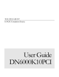
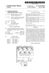
PR-8802
This product manual contains important information about the safe installation and use of this
projector. Please read and follow these instructions carefully and keep this manual in a safe place
for future reference.
PR LIGHTING LTD.
http://www.pr-lighting.com
INDEX
3
4
4
5
6
6
7
9
12
12
12
13
16
17
SAFE USAGE OF THE PROJECTOR
INSTALLING THE PROJECTOR
CONTROL SYSTEM AND POWER CONNECTIONS
DMX TERMINATOR
SETUP OPTIONS-PROJECTOR CONFIGURATION
TO SET THE DMX START ADDRESS
OPERATION MENU
DMX PROTOCOL
INDICATION OF LED DIGITAL TUBE
MAINTENANCE
TROUBLESHOOTING
TECHNICAL DATA
ELECTRICAL DIAGRAM
COMPONENT ORDER CODES
Please note that as part of our ongoing commitment to continuous product development, specifications are subject to change without
notice. Whilst every care is taken in the preparation of this manual we reserve the right to change specifications in the course of
product improvement. The publishers cannot be held responsible for the accuracy of the information herein, or any consequence
arising from them.
Every unit is tested completely and packed properly by the manufacturer. Please make sure the packing and / or the unit are in good
condition before installation and use. Should there be any damage caused by transportation, consult your dealer and do not use the
unit. Any damage caused by improper use will not be assumed by the manufacturer and / or dealer.
ACCESSORIES
These items are packed together with the projector:
Name
Quantity
Barn door
1
Clamps
2
Safety cord
1
This manual
1
2/18
Unit
Pc
Pcs
Pc
Pc
Remark
SAFE USAGE OF THE PROJECTOR
When unpacking and before disposing of the carton, check there is no transportation damage before using the projector.
Should there be any damage caused by transportation, consult your dealer and do not use the apparatus.
The projector can be used indoors and outdoors, IP67.
The projector is not designed or intended to be mounted directly on to inflammable surfaces.
The projector is only intended for installation, operation and maintenance by qualified personnel.
Do not project the beam onto inflammable surfaces, minimum distance is 5m.
5m
Avoid direct exposure to the light from the lamp. The light is harmful to eyes.
Do not attempt to dismantle and/or modify the projector in any way.
Electrical connection must only be carried out by qualified personnel.
Before installation, ensure that the voltage and frequency of power supply match the power requirements of the projector.
It is essential that each projector is correctly earthed and that electrical installation conforms to all relevant standards.
Do not connect this device to any other types of dimmer apparatus.
When the projector is hanged to a high place, please use a safety cord provided to pass through as a secondary safety
fixing for safety reasons. For details, refer to “INSTALL THE PROJECTOR “section.
Make sure that the power-cord is never crimped or damaged by sharp edges. Never let the power-cord come into contact
with other cables. Only handle the power-cord by the plug. Never pull out the plug by tugging the power-cord.
LED lens shall be changed if they have become visibly damaged to such an extent that their effectiveness is impaired, for
example by cracks or deep scratches.
Exterior surface temperatures of the projector after 5 minutes’ operation is 55℃, when achieving steady state it is 70℃.
There is no user serviceable parts inside the projector, do not open the housing and never operate the projector with the
covers removed.
Always disconnect from the mains, when the device is not in use or before cleaning it or
before attempting any maintenance work !
If you have any questions, don’t hesitate to consult your dealer or manufacturer.
3/18
INSTALL THE PROJECTOR
Take 2 clamps and safety cord out from the package and mount 2 clamps on the underside of fixture with 2 retainers
attached to each clamp. Hang the fixture on the structure and fasten the screws attached to each clamp. Always ensure
that the projector is firmly anchored to avoid vibration and slipping whilst functioning. Always ensure that the structure that
you are going to mount the projector is secure and is strong enough to support a weight of PR-8802.
WARNING:
1. The projector MUST be lifted or carried by the HANDLES instead of clamps.
2. For safety the safety cord should afford 10 times of the unit’s weight.
CONTROL SYSTEM AND POWER CONNECTION
Connection between the controller and a projector and between one projector and another must be made with a 2
core-screened cable, with each core having at least a 0.5mm diameter. Please use the projector’s cannon 3- pin signal
input and output cables as connection. The 3-pin signal connections are connected as shown in the figure above.
Note: Care should be taken to ensure that none of the pins touch the metallic body of the plug or each other. The body of
the plug is not connected in any way. The fixture accepts digital control signals in protocol DMX512 (1990).
The amount of projectors connected in parallel is not more than 32. Connect the controller’s output to the first fixture’s
input cable with a 3-pin signal cable, connect the first fixture’s output cable to the second fixture’s input cable and connect
the rest fixtures in the same way. Eventually, connect the last fixture’s output cable to a DMX terminator. Note: Only when
all the start addresses of fixtures are set the same, synchronous control could be achieved.
When the first fixture is not connected to the controller, and all the other connections are the same as above, it is master /
slave mode connection. To achieve master / slave mode, set the first fixture master , the others salve( slave is default).
As for power connections, each projector has to be supplied separately by external power. Use the power cord of each
projector to connect the mains power directly, paying attention to the voltage and frequency marked on the panel of the
projector.
4/18
DMX TERMINATOR
In the Controller mode, at the last fixture in the chain, the DMX output has to be connected with a DMX terminator. This
prevents electrical noise from disturbing and corrupting the DMX control signals.
The DMX terminator is simply an XLR connector with a 120Ω (ohm) resistor connected across pins 2 and 3, which is
then plugged into the output socket on the last projector in the chain. The connections are illustrated below.
DMX TERMINATOR
2
1
3
120
CONNECTION
Connect a 120 (OHM) resistor
across pins 2 and 3 in an XLR plug
and insert into the DMX out socket
on the last unit in the chain.
5/18
PIN 2
PIN 3
SETUP OPTIONS-PROJECTOR CONFIGURATION
Projector configuration can be set conveniently via push-button switch and LED display.
Launch the projector and press button ENTER for more than 5 seconds to unlock the panel, the LCD will show the
function menu of the projector, each main menu has its submenus and each submenu has a specific function. For
details, please see the “OPERATION MENU” section.
Press button UP or DOWN if you want to browse through the various Setup Options. Press button ENTER to save your
settings or enter the next menu. Press button UP or DOWN to shift.
Press button FUNC, it will return to the upper menu one by one or browse through the main menu.
TO SET THE DMX START ADDRESS
Each unit must be given a DMX start address so that the correct projector responds to the correct control signals. This
DMX start address is the channel number from which the projector starts to “listen” to the digital control information being
sent out from the controller. The PR-8802 have 3 DMX modes, which are standard mode, extended mode and short
mode. For example, the standard mode has 11 channels, so set the No. 1 projector’s address 001, No. 2 projector’s
address 012, No. 3 projector’s address 023, No. 4 projector’s address 034, and so on.
Launch the projector. Press button ENTER for more than 5 seconds to unlock the panel.
Press button FUNC, UP or DOWN to find “AddR” menu.
Then press ENTER to show DMX address and press UP or DOWN to set DMX address.
At this time, the address will flash continuously. Press button ENTER to confirm and it means the setting has been
enabled.
Press button FUNC, it will return to the upper menu one by one.
6/18
OPERATION MENU
1st LEVEL
2nd LEVEL
AddR
(DMX address)
XXX
(XXX:1~512)
3rd LEVEL
dmX
(DMX mode)
(Default: STd)
dISP
(Display setting)
(Default: ON)
b-C
Brightness level
control setting
[5][6]
CNFG
(Config settings)
ON(Brightness control is ON)
(Default: OFF)
T-C
Timer control setting
(Default: OFF)
OFF (Timer control is OFF)
ON (Timer control is ON)
ONCA (Only XLR)
ONWR (Only wireless)
DMXS
DMX setting
(Default: ONCA)
PPCA (XLR first)
PRWR (wireless first)
mORS
(Master /Slave Setting)
(Default: SLAVE)
INFO
(Information)
TEST
(Test mode)
mENU
(Operation mode)
STd
(Standard mode)
EXT
(Extended mode)
SHRT
(Short mode)
ON
OFF
(Shut off digital CRT without
pressing buttons in 5 minutes)
OFF(Brightness control is
OFF )
PAIR
Unlink wireless
FACT
(Reset factory setup)
TRmd
[2]
(Transmit parameters )
TImE
(Power on hours)
TEmP
(LED board temperature)
VER
(Version)
R
(Red)
G
(Green)
B
(Blue)
W
(White)
RGb
(Red/green/blue)
Rwb
(Red/white/blue)
RGbw
(Red/green/blue/white)
dmx
(DMX mode)
PR XX
(Preset memory, PR01~PR16)
7/18
WTOC (wireless to XLR)
SLAV
(Slave)
mAST[1]
(Master )
yES
yES
yES
XXXX
XX
X.X.X
4th LEVEL
COL1
(Colour 1)
COL2
(Colour 2)
COL3
(Colour 3)
COL4
(Colour 4)
HOUR
ET XX
(User memory,ET01~ET16)
T-S
[4]
Current time setting
T*B
Timer value and brightness
value setting
XX
[3]
(Number: 0~14 )
XX
(Number: 0~14)
XX
(Number: 0~14)
XX
(Number: 0~14)
MINU
T-ON
[4]
Power on time setting
HOUR
T-OF
Power off time setting
HOUR
MINU
MINU
B-ON
[5]
Power on by brightness setting
B-OF
Power off by brightness setting
B-EN
Check brightness
1-100
1-100
1-101
Note:
[1]. There can only be one main unit set as master at the same single circuit. Please remove DMX single when main
unit function is working.
[2]. When multiple projectors’ work together in synchronous control state, Parameters can be transmitted from the
master projector to the slave projectors in the following conditions, such as DMX channel mode, display setting
status brightness level setting, timer control setting, DMX setting, brightness value setting, timer value setting,
current time value and operation mode (User memory data is included). Please set main unit as master and others
as slave while carrying on transmitting parameters.
[3]. Colour number in user’s memory represents refer to the following table.
Number
0
1
2
3
4
5
6
7
8
9
10
11
12
13
14
Colour
R
G
B
W
RG
RB
RW
GB
GW
BW
RGB
RGW
RBW
GBW
RGBW
[4]. When timer control setting (T-C) is set to ON: Power on time is set to t1, Power off time is set to t2, current time is set
to t3.
If t2 >t1, when t1<=t3<t2, the projector is power on, in addition time of the projector is power off.
If t2 <t1, when t2<=t3<t1, the projector is power off, in addition time of the projector is power on.
If t2 =t1, the projector is power on.
[5]. When brightness level control (b-C) is set to ON: Power on by brightness is set to b1, power off by brightness is set
to b2, current brightness is set to b3.
If b2 >b1, when b1<=b3<b2, the projector is power on, in addition brightness of the projector is power off.
If b2 <b1, when b2<=b3<b1, the projector is power off, in addition brightness of the projector is power on.
If b2 =b1, the projector is power on.
[6]. Brightness level control setting and timer control is a logic and or relationship, if one of them to conform he off
condition, the LED lights turns off.
8/18
DMX PROTOCOL
Short
mode
1
Standard
mode
1
Extended
mode
1
2
FUNCTION
DMX
Dimmer
000-255
Dimming from dark to light
Dimmer Fine
000-255
Dimmer in 16 Bit precision
000
2
2
3
Colour Temperature
001-255
000
3
4
Macros
DESCRIPTION
No effect
Colour temperature adjustment from
3200K to 10000K
No effect
001-015
Colour Temperature 3200K
016-031
Colour Temperature 5600K
032-047
Colour Temperature 7200K
048-063
Colour Temperature 10000K
064-079
Red
080-095
Green
096-111
Blue
112-127
Purple
128-143
Blue and White
144-159
Red and White
160-175
Green and White
176-191
White
192-207
Yellow and White
208-223
Purple and White
224-239
Effect 1
240-255
Effect 2
3
4
5
Red
000-255
Dimming from dark to light
4
5
6
Green
000-255
Dimming from dark to light
5
6
7
Blue
000-255
Dimming from dark to light
6
7
8
White
000-255
Dimming from dark to light
9
Hue
000-255
Hue selection
10
Saturation
000-255
Saturation from shallow to deep
11
Value
000-255
From dark to light
12
Strobe
000-009
No effect
010-255
Strobe speed from slow to fast
7
8
000
9
13
Preset memory
9/18
No effect
001-015
Preset memory 1
016-031
Preset memory 2
032-047
Preset memory 3
048-063
Preset memory 4
064-079
Preset memory 5
080-095
Preset memory 6
096-111
Preset memory 7
112-127
Preset memory 8
128-143
Preset memory 9
144-159
Preset memory 10
160-175
Preset memory 11
176-191
Preset memory 12
192-207
Preset memory 13
208-223
Preset memory 14
224-239
Preset memory 15
240-255
Preset memory 16
000
10
14
User Memory
001-015
User memory 1
016-031
User memory 2
032-047
User memory 3
048-063
User memory 4
064-079
User memory 5
080-095
User memory 6
096-111
User memory 7
112-127
User memory 8
128-143
User memory 9
144-159
User memory 10
160-175
User memory 11
176-191
User memory 12
192-207
User memory 13
208-223
User memory 14
224-239
User memory 15
240-255
User memory 16
000
11
15
Memory Speed
10/18
No effect
No effect
001-015
Speed 1,the fastest
016-031
Speed 2
032-047
Speed 3
048-063
Speed 4
064-079
Speed 5
080-095
Speed 6
096-111
Speed 7
112-127
Speed 8
128-143
Speed 9
144-159
Speed 10
160-175
Speed 11
176-191
Speed 12
192-207
Speed 13
208-223
Speed14
224-239
Speed 15
240-255
Speed 16, the slowest
Note:
**** Channel priority from high to low is as the following: preset memory, user memory, RGBW dimming, HSV
dimming, macro channel;
****When high priority channel is used, low priority channel is no effect.
11/18
INDICATION OF LED DISPLAY
Decimal point of the first character
Decimal point of the third character
Decimal point of the fourth character
Parameters that LED digital tubes display
Blue LED
On
Off
On
Off
On
Off
Flash
DMX signal is OK
No DMX signal
Master / slave signal is OK
No master / slave signal
When setting master mode
When setting slave mode
Parameters not saved, press “ENTER” to save them
On
DMX signal of wireless is OK
Off
No connection to any transmitter
Lost contact with transmitter or contacting
transmitter
Flash
MAINTENANCE
To prolong the life of the projector, it is very important to do the maintenance work. The environment is hash outdoors,
or if the projector is idle for a long time, damp, smoke or particularly dirty surroundings can cause greater accumulation
of dirt on its cover and housing. So it should be cleaned to maintain an optimum light output and at the same time to
prevent it from corrupted by acid gas.
Cleaning frequency depends on the environment in which the fixture operates. Soft cloth and typical glass cleaning
products should be used for cleaning. It is recommended to clean projector at least once every 20 days.
Do not use any organic solvent, e.g. alcohol, to clean housing of the apparatus.
TROUBLESHOOTING
PROBLEM
ACTION
¾
Power connection is not correct.
¾
Power supply is damaged or abnormal. Call a qualified personnel
to fix it.
The projector doesn’t switch on
¾
Connection of control board is not correct. Call a qualified
personnel to fix it.
The projector can be turned on, but LEDs do
¾
not emit light and are out of control.
Connection of LED board is not correct. Call a qualified
personnel to fix it.
The lamp comes on but the projector
¾
Make sure that the projector is correctly configurated.
doesn’t respond to the controller
¾
Replace or repair the DMX cable.
¾
The projector is too hot. Take ventilation measures to make it
The beam appears dim
cool.
12/18
TECHNICAL DATA
VOLTAGES:
100V/120V/200V/220V /230V/240V AC, 50/60Hz
POWER CONSUMPTION:
700W@220V
LED:
Power consumption
3W
Quantity
216(54R+54G+54B+54W)
Manufacturers Rated LED Life
50000 Hours
COLOURS:
RGBW colours mixing
Linearly colour temperature correction
DIMMER:
0-100% linearly adjustable
STROBE:
1~20F.P.S
BEAM ANGLE:
32°(Optional 26°,57°)
LENS ANGLE:
14°(Optional 8°, 45°)
CONTROL:
DMX512, 3 pin interfaces
7 channels in short mode, 11 channels in standard mode, and 15 channels in extended mode
Wireless DMX signal transmission
Master /Slave mode
16 preset memories
16 user memories
Preset memories and user memories can be load by control channels,16 level speeds adjustable
Self-test mode
OTHER FUNCTIONS:
LED board temperature display
Fixture usage time display
Brightness level control
Timer control
DMX mode, setting status, operation mode and user memory data can be transmitted by synchronous control
13/18
HOUSING:
High-intensity die-casting aluminum, IP67
WORK ENVIRONMENT TEMPERATURE:
-20°C~40°C
WEIGHT:
27kg
SIZES:
See it below
LIGHT OUTPUT:
14/18
Optional lens 8°:
Optional lens 45°:
15/18
"#
$
"#
%
!
!
(-
%
$
!
/
.
'( )*+,(
"#
&
,
& '( )*+,(
(-
!
&
,
. #
$
.
#
%
! $0
.
$
"#
$
COMPONENT ORDER CODES
NAME
LED LENS
LED LENS
LED LENS
SIGNAL CABLE
SIGNAL CABLE
SIGNAL CABLE
SIGNAL CABLE
POWER CORD
POWER SUPPLY
LED CONTROL BOARD
LED BOARD
LED DRIVE BOARD
PART NO.
070070040
070070015
070070041
120080030B
120080031B
120080032
120080033
120080034A
192010142
230060083
230060085
230060086
17/18
QUANTITY
216
216
216
1
1
1
1
1
2
1
2
2
REMARK
14°
8°(optional)
45°(optional)
1.7m,male
1.7m,female
0.3m,male
0.3m,female
1m,female
PR LIGHTING LTD.
PR New Hi-tech Science Park, 1582 Xingye Avenue
Nancun Panyu, Guangzhou, 511442 China
TEL: +86-20-3995 2888
FAX: +86-20-3995 2330
P/N: 321030053
Version: 20101230
18/18