1
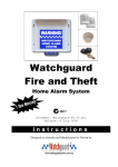
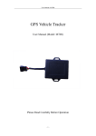
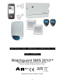
Inbox 11:21pm WGSMS2010. Perimeter Alarm – Zone 1. INSTRUCTION MANUAL VERSION 1.12 MODEL: WGSMS2010 Watchguard SMS 2010 Mobile Phone Monitored Alarm System via SMS with Wireless Detectors, Remote Controls & Siren RoHS N517 COMPLIANT Designed in Australia. Made in Taiwan 1 Contents Contents ............................................................................................................................................................. 2 Quick Reference Guide...................................................................................................................................... 3 1. Introduction .................................................................................................................................................... 4 1.1 Watchguard SMS 2010 Features ........................................................................................................... 4 1.2 Main Components:.................................................................................................................................. 5 1.2.1 Optional Components – Compatible Sirens ................................................................................... 6 1.2.2 Optional Components - Accessories: ............................................................................................. 7 2. Installation ...................................................................................................................................................... 8 2.1 Planning the Installation.......................................................................................................................... 8 2.2 Installation Sequence.............................................................................................................................. 8 2.2.1 Setting up the SIM Card.................................................................................................................. 9 2.2.2 Main Control Unit ............................................................................................................................ 9 2.2.3 Wireless PIR Detectors................................................................................................................. 10 2.2.4 Wireless Panic Buttons ................................................................................................................. 15 2.2.5 Wireless Smoke Detectors ........................................................................................................... 16 2.2.6 Wireless Reed Switches ............................................................................................................... 18 2.2.7 Wireless External Siren................................................................................................................. 19 2.2.8 Wireless Solar Siren ..................................................................................................................... 22 2.2.9 Wireless Keypad ........................................................................................................................... 24 2.3 Configure Arm/Disarm Confirmation Reports ....................................................................................... 30 2.3.1 Set-up Arm/Disarm Confirmation Reports .................................................................................... 30 3. Operation ..................................................................................................................................................... 31 3.1 Master key switch on Main Control Unit ............................................................................................... 31 3.2 Exit & Entry Delays ............................................................................................................................... 31 3.2.1 Exit Delay...................................................................................................................................... 31 3.2.2 Entry Delay (For Use With The Optional Wireless Keypad) ......................................................... 31 3.3 Red LED Indicator Main Control Unit.................................................................................................... 31 4. Alarm Modes ................................................................................................................................................ 32 4.1 Away, Home and Panic Modes............................................................................................................. 32 4.2 Disarming the Unit: ............................................................................................................................... 32 4.3 Remote Control Functions .................................................................................................................... 33 4.3.1 Button 1......................................................................................................................................... 33 4.3.2 Button 2......................................................................................................................................... 33 4.3.3 Buttons 1 and 2............................................................................................................................. 33 5. Programming................................................................................................................................................ 34 5.1 Main Control Unit Programming............................................................................................................ 34 5.1.1 Add a new remote......................................................................................................................... 34 5.1.2 Delete all remotes ......................................................................................................................... 35 5.1.3 Add a detector............................................................................................................................... 35 5.1.4 Delete a detector........................................................................................................................... 36 5.2 Zone Feature Programming.................................................................................................................. 36 5.2.1 Zone feature programming ........................................................................................................... 36 5.2.2 Turning zone supervision on or off ............................................................................................... 37 5.2.3 Turning siren arm / disarm beeps on or off................................................................................... 37 5.3 Basic SMS Functions ............................................................................................................................ 38 5.4 Phone Number Memory........................................................................................................................ 39 5.4.1 To Change Your PIN code............................................................................................................ 39 5.4.2 To Change The ID Of The System ............................................................................................... 39 5.4.3 To Add Phone Numbers To The System...................................................................................... 40 5.4.4 To Read Phone Numbers From The System ............................................................................... 40 5.4.5 To Erase Phone Numbers From The System............................................................................... 41 5.4.6 SMS Controlled Output ................................................................................................................. 41 5.5 SMS Commands List ............................................................................................................................ 42 6. Warranty Terms ........................................................................................................................................... 43 6.1 Warning Limitations & Warranty ........................................................................................................... 43 2 Quick Reference Guide 1. Set-up the SIM card for operation in the system. (ref. 2.2.1 Installation: Setting up the SIM Card – Page: 9) 2. Set-up the PIN code. (ref. 5.4.1. To Change Your PIN code – Page: 35) 3. Set-up the Identification of the alarm system. This ‘Identification’ is a description for the system that appears at the start of every SMS message you will receive from the alarm system. (ref. 5.3.5 To Change The ID Of The SMS message – Page: 37) 4. Set-up the Phone Numbers that the system will send messages to. Refer to the sections Adding/Erasing Phone Numbers from the system’s memory. (ref. 5.3. Phone Number Memory – Page: 35) NOTE: To receive a FULL list of all commands, send your PIN code to the Main Unit. Please note down the relevant details for the alarm system. i.e. The phone numbers that have been programmed into the system and the phone number of the actual Watchguard SMS 2010 (WGSMS2010) alarm system. PROGRAMMED PHONE NUMBERS REFERENCE WGSMS2010 SIM Card Phone Number This is the phone number of the alarm system. Stored Phone Numbers Telephone 1 Telephone 2 Telephone 3 Telephone 4 Telephone 5 3 1. Introduction As Australia's leading designer & manufacturer of quality wireless security systems we are proud to release our latest model that enables 2-way communication between you and your alarm via your mobile phone. 1.1 Watchguard SMS 2010 Features Features: • Quick and simple to install – very easy to use! • Remote Controls to arm / disarm your system or send a panic alarm from anywhere within operating range on your premises. • The remote controls utilise Code Hopping technology to protect against scanning and code grabbing, with more than 4 billion security combinations chosen at random. • 8 Zone controller with battery back-up, allowing up to 8 wireless sensor devices including smoke detectors, passive infrared movement sensors (both indoor and outdoor versions) and reed switches for doors and windows. • Long-life lithium batteries used on all sensors as well as automatic low battery warning to indicate when they need replacing. • Tamper detection on all system parts including panel and wireless sensors. • Extra wireless sensors are available including door-window reed switches, Wireless Solar Siren and AC Powered Siren (wirelessly triggered; includes back up battery). • Optional compatibility with external siren. • Anti tamper protection, AC failure notification, battery failure notification, supervision failure notification (if the external siren does not report to the main unit for 24hours), powerful siren with auto 5 minute timeout and blue flashing strobe for ARM, DISARM and HOME ARM visual conformation. • Radio interference detection for maximum system integrity (optional) • Confirmation SMS reports of arm/disarm (programmable) • SMS notification for all alarm events • Easy programming using DIP switches • Latest generation radio receiver – up to 300m line of sight 4 1.2 Main Components: The below components are included in the Watchguard SMS 2010 alarm system package: 1 Main Control Unit & Keys 2 Remote Controls 3 12V DC Power Supply 4 Wireless Passive Infrared Detectors 5 Wired Compact External Siren 6 Mounting Materials 5 1.2.1 Optional Components – Compatible Sirens Wireless Sirens: 1. Wireless Triggered Siren (AC Powered) Part # WSIREN Wireless External Siren with flashing blue strobe and backup battery. 10m of pre-terminated cabling for ‘plug-secure’, DIY friendly installation. Includes low voltage plug-pack. Sends tamper, low battery and supervision signals. 2. Completely Wireless Solar Siren Part # WSSOL The Wireless Solar Siren requires no cables, with an inbuilt solar panel to charge its 6V 1.2Ah internal battery. Backup battery included. Can operate continually for 40 days without sunlight once charged. Incorporates powerful siren and flashing blue strobe. Tough, weatherproof polycarbonate housing. 3. Wireless Compact Siren Part # WSSENTINEL Compact design Wireless External Siren with flashing blue strobe. Includes low voltage plug-pack. Hard Wired Siren: 1. Hard Wired External Siren Part # COS-PLUG Hard Wired External Siren with high visibility flashing blue strobe and tamper switch. Housed in a moisture and UV resistant, highly durable, attractive industry standard casing. All cabling is pre-terminated for easy installation. Includes rear protective cover. 6 1.2.2 Optional Components - Accessories: 1. Wireless Keypad Part# WKP A wireless keypad can be placed inside the entrance to your premises, allowing people to arm and disarm the system using a PIN code instead of remote controls. This enables multiple user access without needing extra remote controls. 2. Large Wireless Keypad Part # WKPL Large conventional size wall mountable keypad with flip-down front cover – allows for arming and disarming of system using PIN code. Powered by 9V Battery. Backlit keys for night time illumination. 3. Wireless Smoke Detector Part # SMODETW The Wireless Smoke Detector will trigger an alarm whenever smoke or fire is detected. The detector contains a long life battery and the system will notify you when it requires replacing. 4. Wireless Supervised PIR Detector (Outdoor) Part # PIRWOD Fully sealed UV resistant housing for outdoor use. Four selectable coverage patterns (wide angle 10m, curtain 10m, long range 20m & vertical curtain 3m). Wirelessly communicates alarm, low battery and supervision signals. High quality TAKEX sensor, made in Japan. 5. Wireless Emergency Pendant Part # WPANIC Designed with the elderly or invalid person in mind. Large rubber button. Nylon lanyard included. Splash proof. Dipswitch Coding. 6. Wireless Reed Switch Part # WREEDI The Wireless Reed is used for detecting the opening of windows or doors. They contain long life lithium batteries that last up to 5 years, and the system will automatically notify you when they need replacing. 7 2. Installation 2.1 Planning the Installation To get the best possible protection from your Watchguard SMS 2010 alarm system, it is imperative that you follow the following guidelines on where to place the system components. Below is a diagram of typical locations to place the Main Control Unit and wireless accessories. 2.2 Installation Sequence A variety of accessories are available with the Watchguard SMS 2010 alarm system. This guide provides installation details for each of these accessories, following the setting up of the SIM Card and the mounting of the main control unit. 1. Setting up the SIM Card. 2. Main Control Unit. 3. Install Accessories. Once the Main Control Unit is mounted, you will then need to set-up and install any accessories you have. a. Wireless PIR Motion Detectors b. Panic Buttons c. Smoke Detectors d. Wireless Reed Switch and Shock Sensors e. External Hard-Wired/Wireless Sirens f. Wireless Keypad 4. Configure Arm/Disarm Confirmation Reports. 5. Customise Programming. 8 2.2.1 Setting up the SIM Card IMPORTANT NOTE: The Watchguard SMS 2010 requires a GSM SIM Card. You must purchase this from a telecommunications provider. Also, it must not be PIN code locked – please follow the instructions below to ‘deactivate (turn off) the PIN code’ if locked. If the SIM asks you for a PIN code, place it in an existing mobile phone and deactivate (turn off) “PIN code request.” You may need to refer to your mobile phone manual on how to do this. After deactivating the request, insert the SIM card into the Watchguard SMS 2010. Save the system’s phone number in your phone to easily recall for sending SMS commands e.g. ‘WGSMS2010’ or Home Alarm or another meaningful name. This way when the system calls because an SMS did not get through or sends a normal status message you will know that it is the alarm that has attempted to contact you and be able to take immediate action. 2.2.2 Main Control Unit The Main Control Unit requires 12VDC power – the plug pack must be connected to AC voltage at all times. Therefore, it should be located as close as possible to a power outlet, preferably mounted out of sight. For maximum wireless range, mount the unit at a height of 1.5m or greater from the ground and ensure there are no metal objects directly adjacent to the antenna. Note: Make the antenna as straight as possible, as even small bends can reduce the wireless range significantly. DO NOT ever attempt to shorten or lengthen the antenna. Note: The Watchguard SMS 2010 system has been designed with most single and two storey residential / business premises in mind. In some instances however, (due to the construction of the building) range may be diminished, and this may require you to either locate the main control unit, the wireless solar siren, or the alarm detector closer to one another to achieve reliable performance. Carrying out a Walk Test (Refer Page 13) will ensure best operation. Mounting the Main Control Unit Antenna – Keep vertical & straight 1. Drill the mounting holes (7mm Diameter) into the chosen location (preferably 1.5m or greater from the floor). 2. Install the unit so the antenna is straight and vertical. 3. Push the supplied wall plugs into the holes then mount the unit on the wall using the supplied screws. 4. Plug the power adapter (with the right angle plug) into your power point (leaving it switched off), and connect the right angle plug into the Main Control Unit. 5. Insert the SIM card into the slot and lock it in place using the slide. 6. Turn the power point on where the power adapter is connected. 7. Now you can setup SMS messaging (see page 35). NOTE: Ensure you hold a record of the programmed numbers and the unit’s SIM card number – this can be done in the ‘Programmed Numbers Reference’ at the start of this manual. Note: The main control unit must also be turned on with the unit keys provided. The keyswitch is primarily used for programming in features and optional accessories and is not necessary after system setup. Once the alarm is configured, the main unit keyswitch should remain on. See page 28 for more information on the keyswitch. 9 2.2.3 Wireless PIR Detectors This section shows you how to install wireless PIR detectors (PIRW3) for your system. a) Systems with packaged wireless PIR detectors should already be learnt into the Main Control Unit. If your detectors have a sticker with a zone number on the back, then they are already learnt into the system. Follow the Set-up a pre-learnt wireless PIR detector procedure for each of these detectors that you have. b) If you have purchased additional detectors, you will need to learn them into the Main Control Unit. Follow the Set-up and learn-in a wireless PIR detector procedure for each of these detectors that you have. Refer to the Programming chapter later further in the manual if you wish to change the Home and Away settings for a zone. a) Set-up a pre-learnt wireless PIR detector Open the front cover of the detector and remove the plastic insulator from the battery. Wait 3 minutes for the detector to warm up. Set dipswitches 1 and 3 on the Main Control Unit to ON. Open and close the front cover of the detector. The detector will now enter Walk Test mode. Walk test the detector and adjust the facing angle as necessary so that the red light on the detector turns on whenever you walk past it. The unit will beep out the zone number of the detector whenever it is triggered (i.e. zone 1 will beep once). The unit will not beep out the zone number if the radio signal strength is not strong enough. Mount the detector if the walk test was successful. Press button 2 on the remote to exit Walk Test mode. Set all the dipswitches to off. 10 b) Set-up and learn-in a wireless PIR detector Open the front cover of the detector and remove the plastic insulator from the battery. Wait 3 minutes for the detector to warm up. Set the dipswitch to ON for the zone you wish to learn the detector into. Press the ADD button on the Main Control Unit. Remove the front cover of the detector. Press and release the tamper switch. The Main Control Unit should then beep a number of times; to indicate which zone the detector has been learnt into. The system will now automatically enter Walk Test mode. Walk test the detector and adjust the facing angle as necessary so that the red light on the detector turns on whenever you walk past it. The unit will beep out the zone number of the detector whenever it is triggered (i.e. zone 1 will beep once). The unit will not beep out the zone number if the radio signal strength is not strong enough. Mount the detector if the walk test was successful. Set all the dipswitches to off. 11 c) About the wireless PIR detector The detector is a high quality infrared movement detector, which is battery operated and communicates with the Watchguard SMS 2010 alarm system via radio frequency (RF) transmission. This detector is very easy to install, provides excellent detection sensitivity and has a long battery life (approximately 3 years). This detector transmits four different codes to the main control unit. 1 Alarm Sent when a valid movement is detected 2 Tamper Sent when the detector case is opened 3 Supervision Sent every 2.5 hours to the main control unit 4 Low Battery Sent when the batteries need replacing During the warm up period, (first 3 minutes after installing the batteries) the detector will not respond to the tamper switch or to movement in front of the detector. You must wait 3 minutes before it will respond to movement This detector has Intelligent Power Saving (IPS). This means that in normal operation the lights will not flash every time you move in front of the detector. When the red light flashes on for 1 second, this means that the detector has picked up and validated body movement (or an intruder) and an alarm code is transmitted. The detector will now go into IPS mode for approximately 3 minutes. During this time the detector will not trigger and no lights will turn on. d) Tips for positioning Mount the detector on your wall at a minimum height of 1.8 metres and maximum of 2.1 metres (lower is better). Always mount your PIRW so that an intruder has to walk across its zones (i.e. walk past the detector, not towards it). Don’t mount detectors facing glass doors or windows. Always mount above windows and doors to look inside. Don’t mount detector facing hot areas or areas where the temperature may change suddenly (e.g. open fire places, direct sunlight or air conditioning vents). Select a location where the detector can provide the best detecting range. Always ensure that you do not cover an area with multiple detectors, so as to avoid simultaneous transmission back to the Main Control Unit. The receiver can only decode one coded signal at any given time. If the Main Control Unit is mounted close to metal frames or doors, this may reduce the radio transmitting range. The higher the mounting and straighter the antenna, the better the range! The detector is not waterproof and is designed for indoor use only. 1. 2. 3. 4. Firstly, the mounting bracket must be fixed to the wall using the self-tapping screw. Mounting should be at a minimum height of 1.8 metres and maximum of 2.1 metres. Drill a 5mm diameter hole (at least 30mm deep) into the wall for mounting the detector bracket/socket base. Push the wall plug into the hole then screw in the mounting bracket. It will clip into the base. The detector can now be clipped onto the swivel bracket. See diagram below. It is vital that the detector is tested carefully for each installation. At 25°Celsius, the detector should have a detection range of approximately 10 metres and a scope angle of 90°, i.e. 45° either side of the centre position straight ahead of the lens. You can check how well the detector is functioning, by performing a walk test. 12 e) Perform a walk test Remove the front cover off the detector via the clip at the top. The green and red lights will flash together, 6 times, to indicate that the detector has entered test mode. Replace the front cover. The detector will stay in walk test mode for 3 minutes. It may be triggered as often as desired during this period. When movement is detected the green light will flash to indicate one pulse count. When 3 pulse counts are detected the red light will flash to indicate a valid movement and that the alarm code signal has been sent back to the main control unit. After the alarm code signal has been received, the internal screamer will beep the number of times of the zone that has been triggered, ie: two beeps for a zone 2 detector. Detectors, which have been set to 24-hour mode, will still trigger the alarm. If a tamper switch is pressed on the main control unit or a wireless detector the internal screamer will beep once. By following this process, test the range of your detector setup, acknowledging the beeping out of the zones by the main control unit. If the detector does not trigger these beeps from the main control unit, you may need to reposition your detectors closer to the main control unit. 13 The Watchguard PIR detectors have a special firmware known as Dual Edge Sensing (DES). This enhances the reliability of the detectors in all environments. DES is explained further below: f) About Dual Edge Sensing (DES) Technology Side view detection pattern in optimal temperature environment (3ft) (13ft) (30ft) (60ft) This detector has Dual Edge Sensing (DES) Technology, developed to eliminate false alarms yet still provide maximum security. The detector uses a pattern of infrared beam zones to sense body movement. The detection pattern in an optimal temperature environment is shown opposite. Each time you walk into or out of an infrared beam zone this will be sensed and processed by the DES technology built into the detector. The red trigger light will not turn on until the detector has made valid movement detection in normal mode. This will only happen if the detector is not in Intelligent Power Saving (IPS) mode. Trigger examples in ‘least sensitive’ mode When set to least sensitive, the PIR must receive 3 pulses before it will trigger. 2 of the 3 pulse counts must be for different zones. Both of the examples to the left will trigger the PIR, provided movements 1 to 4 are made within 10 seconds. Trigger examples in ‘most sensitive mode When set to most sensitive, the PIR must only receive 2 pulses before it will trigger. Both pulse counts must be from different zones. This example will trigger because two separate zones are crossed. 14 No trigger examples In this example, the PIR will not trigger. This is because the two pulse counts aren’t for two separate zones. 2.2.4 Wireless Panic Buttons This section shows you how to install wireless panic buttons (WPANIC) for your system. • If your system came with wireless panic buttons, they should already be learnt into the Main Control Unit. No further set-up is required. • If you have purchased additional panic buttons, you will need to learn them into the Main Control Unit. Follow the Set-up and learn-in a panic button procedure for each of the panic buttons that you have. a) Set-up and learn-in a panic button Dipswitches 12V Battery Open the panic button, and set the dipswitches to a random combination. Close the panic button. Set the dipswitches on the Main Control Unit to the zone you wish to learn the panic button into. Press and release the ADD button on the Main Control Unit. Press and hold down the panic button until the Main Control Unit beeps. It will beep a number of times corresponding to the zone you have learnt it in to. Set the dipswitches back to OFF 15 2.2.5 Wireless Smoke Detectors This section shows you how to install wireless smoke detectors (SMODETW) for your system. Please read the Smoke detector mounting information section before permanently fixing the detector. • As smoke detectors are optional accessories with the Watchguard SMS 2010 System, you will need to learn them into the Main Control Unit. Follow the Set-up and learn-in a smoke detector procedure for each of the smoke detectors that you have. Note: Wireless Smoke Detectors require a 9VDC battery to operate. Do not repair the smoke alarm yourself. It contains an extremely small amount of a radioactive element in the dual ionisation chamber. a) Smoke detector mounting information • • • • • • • • • • • • • • Locate an alarm for each separate sleeping area in the immediate vicinity of the bedrooms. Try to protect the exit path as the bedrooms are usually farthest from an exit. If more than one sleeping area exit, locate additional alarms in each sleeping area in the immediate vicinity bedrooms. Locate additional alarms to PROTECT any stairway as stairways act like chimneys for smoke and heat. Locate at least one alarm on every floor level. Locate an alarm in every room where a smoker sleeps. Locate an alarm in every room where electrical appliances are operated (i.e. portable heaters or humidifiers). Locate an alarm in every room where someone sleeps with the door closed. The closed door may prevent the alarm from waking the sleeper. Smoke, heat and other combustion products rise to the ceiling and spread horizontally. Mounting the alarm on the ceiling in the centre of the home places it closest to all points in the room. Ceiling mounting is preferred in ordinary residential construction. For mobile home installations, select a location carefully to avoid thermal barrier that may form at the ceiling. For more details see Mobile Home installation overleaf. When mounting alarms on the ceiling locate it at a minimum of 300mm from the side wall and 300mm from any corner. When mounting alarms on a wall, use an inside wall with the alarm of a maximum of 300mm below the ceiling but not exceeding 600mm. NOTE: The performance of smoke alarms mounted on walls is unpredictable and that this mounting is not recommended when ceiling mounting can be implemented. When mounting the alarm at the apex of a sloping ceiling it should be located a minimum of 500mm from the apex but not exceeding 1500mm. (See diagram). Locate smoke alarm at both ends of a bedroom hallway if the hallway is more than 9m long. We do not recommend installation in areas of high condensation such as bathrooms due to potential for false alarms. 16 b) Set-up and learn-in a smoke detector Set the dipswitches to the zone you wish to learn the smoke detector as. In the picture on the left it is set to zone 1. Open the back cover of the detector. Insert the supplied 9VDC battery so that the contacts are touching. Make sure the battery holds down the red tamper switch. Close the back cover of the detector. ADD A Press the ADD button on the main control unit. Press and hold the button on the smoke detector until it beeps. Set the dipswitch to the zone the detector was learnt in to (is already set if following this guide from the beginning). In the picture on the left it is set to zone 1. IMPORTANT: Press and release the tamper button on the main control unit. The smoke detector will beep a number of times to inform you what operation mode it is using. Continue pressing and releasing the tamper button until you hear 4 beeps. This puts the smoke detector in 24 Hour Zone Mode – this means that if the smoke detector is triggered, the alarm will sound whether the system is armed or disarmed. If you are unsure of the mode your detector is in, please refer to manual Section 5.2 – Zone Feature Programming for further assistance. Set the dipswitches back to OFF Mount the smoke detector in a suitable location. 17 2.2.6 Wireless Reed Switches This section shows you how to install wireless reed switches (WREEDI) for your system. • Reed switches are optional accessories, which must initially be learnt into the Main Control Unit. However, if these detectors have previously been learnt in and require setting up, follow the Set-up a pre-learnt reed procedure for each of these detectors that you have. • If the accessories are newly purchased (as in the case of a new Watchguard SMS 2010 System where they are purchased as an option), you will need to learn them into the Main Control Unit. Follow the Set-up and learn-in a reed procedure for each of these detectors that you have. a) Set-up a pre-learnt Reed Switch Open the detector and remove the plastic insulation tabs from the battery, so that the contacts are touching. Mount the detector in a suitable location using the screws provided. (See installation example – Mounted on doorway Fig 1.) - Mount the large sensor body on the stationary part of the door or window & the smaller magnet on the moving part. IMPORTANT NOTE: The gap between the mounting surface and screw must not exceed 3.0mm (as shown below) Gap MUST NOT exceed 3.0mm Figure 1. b) Set-up and learn-in a Reed Switch Set the dipswitches to the zone you wish to learn the reed switch into. In the picture on the left it is set to zone 1. Open the detector and remove the plastic insulation tabs from the battery, so that the contacts are touching. Move the magnet away so that the detector triggers. The Main Control Unit should beep a number of times to inform you what zone the detector is learnt into. Set the dipswitches back to OFF 18 2.2.7 Wireless External Siren This section shows you how to install a wireless external siren for your system. The External Siren should be mounted at the front or the front side of the building so as to provide maximum visual deterrent and to allow neighbours to identify that it is your system that has been activated. The mounting position must NOT be exposed to direct rain or other water sources. This means that under an eave or roof overhang is a good location as shown in the diagram below. The position should allow line of sight viewing from both the street (for visual deterrent) and from your main point of entry (for visual confirmation of arming/disarming). Use the wall plugs and screws provided if suitable for your particular building construction. 19 To Power Point Connect to Power a) Installing the Siren Unit (refer to pictures opposite) 1. Drill mounting holes (7mm diameter, 25mm minimum in depth) into the chosen wall. 2. If a masonry wall, use the green star plugs. Press each one into the 4 main mounting holes. 3. Make a 12mm hole and feed the 10m of low voltage power cable through the wall and up into the ceiling for power. 4. Screw the top 2 screws half way in. 5. Place the unit to support itself from the top 2 screws through the key shape holes at the top of the main control unit 6. Screw in and tighten the bottom two mounting screws then tighten the top two screws. 7. Now run the 10m of low voltage cable through the roof to the closest power point. 8. Plug the power adapter into your power point, connect the 10m cable and then turn the power point on. Plug on power adapter connected to power point Socket on 10m of cable from the siren 9. Now turn the key switch on the outdoor siren to the ON position (clockwise). 10. Perform Wireless Siren Auto Test (shown below). To test signal strength/coverage of the main unit to Siren follow the procedure below. b) Wireless Siren Auto Test 1. 2. Set dipswitches 1 and 5 to on. The strobe on the siren will flash every 5 seconds, and the main unit will beep out the signal strength every 5 seconds. The beeps range from 1-10. The minimum acceptable strength is 3. Note: if the 3 beeps are not achieved, relocate the siren slightly. If the 3 beeps are still not achieved then relocate the siren closer to the main unit. 20 Note: If for any reason your external siren does not beep when you arm & disarm your Watchguard SMS 2010, simply turn off the External Siren Key switch, wait for 10 seconds and then turn back on again. Now immediately (within 3 seconds) arm the system using your remote control. You should now hear 1 beep from the external siren. c) Learning in the Siren Unit to the Main Control Unit 1. Switch ON the wireless siren by turning the key-switch to the ON position. The strobe will flash for a few seconds. This means the device is active and ready to learn in the Watchguard SMS 2010. Immediately press Button 1, then Button 2. 2. Immediately arm and disarm the Watchguard digital by using the remote control. 3. If the learning is successful, the Wireless Siren will respond to the Watchguard Digital when armed and disarmed. The Wireless Siren will beep once when armed and twice when disarmed. 4. To finish up the test, confirm the LED on the siren cover is flashing when the alarm is armed. NOTE: Only ONE Wireless External Siren is compatible with the Watchguard SMS 2010 alarm system. If you require more than one siren, Wireless Solar Sirens should be installed instead. Wireless External Sirens and Wireless Solar Sirens cannot be used together on the system. 21 2.2.8 Wireless Solar Siren This section shows you how to install a wireless solar siren for your system. The Wireless Solar Siren must be mounted in a position that provides both maximum visual deterrent and maximum sunlight coverage. The mounting position should be located at the front or the front side of the building so as to provide maximum visual deterrent and to allow neighbours to identify that it is your system that has been activated. The position should allow line of sight viewing from the street for visual deterrent and from your main point of entry for visual confirmation of arming and disarming. The position should be at a height that is relatively inaccessible to an intruder. The mounting position should allow for as much sunlight coverage time as possible. Ideally it should be located on a southerly facing wall (northern hemisphere) or northerly facing wall (southern hemisphere). A westerly or easterly facing wall would suffice in either hemisphere. Avoid any shadows from neighbouring walls, tress and roof overhangs to affect the performance of the solar panel. Remember in winter the sun is lower in the sky and you should avoid any winter shadows. If mounting under a roof overhang, position as low as possible to allow as much sun exposure time as possible, however still maintaining a height relatively inaccessible to an intruder. Positioning in Northern Hemisphere Positioning in Southern Hemisphere 22 a) Mounting a wireless solar siren Use the wall plugs and screws provided if suitable for your particular building construction. Figure 1 Remove the holding screw from the base of the unit and hinge off the front plate. 2. Use the template provided to mark the position of the four fixing holes on the external wall. 3. Drill mounting holes (7mm diameter, 25mm minimum in depth) into the chosen wall. 4. If a masonry wall, use the larger wall plugs provided. Press each one into the 4 main mounting holes. 5. Screw the top 2 screws half way in. 6. Place the back-plate to support itself from the top 2 screws through the key shape holes at the top of the main control unit 7. Screw in and tighten the bottom two mounting screws then tighten the top two screws. 8. Change the dipswitches on the solar siren to a random combination. This ensures that the siren transmits a unique code. 9. First connect the 9V initial power up battery inside the unit to the clip-on connectors. Then connect the rechargeable battery to the charging leads red to red (+) and black to black (-). See figure 3. Strobe Top mounting holes Back-plate 1. Bottom mounting holes Back-plate holding screw Figure 2 10. Hinge the front cover locating tabs over the top edge of the back-plate, and push the base of the siren cover in place. The strobe will flash momentarily, if not remove the siren and replace it again, and secure the lower fixing screw. 11. Press and hold button 1 on one of the remote controls for 3 seconds. The strobe will start flashing and the internal screamer will start sounding. If not either the Wireless Solar Siren unit or the Main unit need to be relocated so that they are closer together. Press button 2 to stop the siren sounding. How to learn in the Solar Siren Set the dipswitches on the Main Control Unit so they are the same as the dipswitches on the solar siren. Hold the ADD button down and turn the Main Control Unit ON using the master key. When you hear the solar siren beep, turn the dipswitches on the Main Control Unit OFF. Figure 3 23 2.2.9 Hard Wired External Siren This section shows you how to install a hard wired external siren for your system. The External Siren should be mounted at the front or the front side of the building so as to provide maximum visual deterrent and to allow neighbours to identify that it is your system that has been activated. The mounting position must NOT be exposed to direct rain or other water sources. This means that under an eave or roof overhang is a good location as shown in the diagram below. The position should allow line of sight viewing from both the street (for visual deterrent) and from your main point of entry (for visual confirmation of arming/disarming). Use the wall plugs and screws provided if suitable for your particular building construction. a) Installing the COS-PLUG Siren Unit (refer to pictures opposite) 1. Drill mounting holes (7mm diameter, 25mm minimum in depth) into the chosen wall. 2. If a masonry wall, use the green star plugs. Press each one into the 4 main mounting holes. 3. Make a 12mm hole and feed the 20m cable through the wall and to the main control module. 4. Screw the top 2 screws half way in. 5. Place the unit to support itself from the top 2 screws through the key shape holes at the top of the main control unit 6. Screw in and tighten the bottom two mounting screws then tighten the top two screws. 7. Now run the 10m of low voltage cable through the roof to the closest power point. 8. Plug the cable into the main control unit as below. 24 2.2.10 Compact Hard Wired Siren a) Mounting a Compact Hard Wired External Siren – W24-PLUG Remove the 2 screws from the main unit as per Fig 1. and remove front cover from the siren. Remove screws located on both sides of the cover Figure 1 Align siren unit & mark 3 mounting holes. Align the siren backing plate in your chosen location and mark the 3 mounting holes as per Fig 2. Drill mounting holes (7mm diameter, 25mm minimum in depth) into the chosen wall. If a masonry wall, use the green star plugs. Press each one into the 3 main mounting holes. Make a 12mm hole and feed the 20m of cable through the wall and to the main control module. Fit the siren cover back on to the backing plate a fasten with screws Figure 2 Plug the cable into the main control unit as per Fig3. Figure 3 25 2.2.11 Wireless Keypad This section shows you how to install a wireless keypad for your system. The Wireless Keypad is designed for use with your Watchguard SMS 2010 Alarm System, offering arm, disarm, home arm and panic functions. The Wireless Keypad offers the security of a user-programmable 4 Digit PIN code. The Wireless Keypad is ideal for the following situations: • Where you have a need for more than 8 remote controls that your Watchguard SMS 2010 Alarm can accept, or for instances where you do not wish to supply remotes. • Where the added security of a PIN code is desired to activate the system, with the added ability to easily change the PIN code at any time. • Where you would like a wall-mounted keypad, rather than carry a remote control. The Wireless Keypad also offers the following: • Tamper protection – any attempt to open the casing of the keypad will initiate a complete alarm event even if the system is disarmed. • Auto Lockout – if a sequence of more then 16 incorrect key presses is entered the keypad will automatically be disabled for 1 minute. If keypad is disabled 3 times consecutively a keypad tamper event will be triggered. a) Insert Battery Remove the fixing screw from the bottom of the Wireless Keypad and remove the back-plate. Remove the battery holder fixing screws. Connect the 9V battery provided to the battery clip and replace battery holder and back-plate fixing screws. The Wireless Keypad is suitable for mounting either indoor or outdoor as it is water resistant. It should be mounted at the main point of entry of the premises. To cover multiple points of entry additional Wireless Keypads may be used. The mounting position must be isolated from any metallic objects or framework as this could diminish the radio range. 26 b) Selecting a mounting location Choose a suitable location Hold the Wireless Keypad in the desired location. + 1 Press and hold the two buttons shown together for 3 seconds 2 The alarm should start sounding. If the alarm did not sound then the Wireless Keypad relocated slightly closer to the main unit and retested. Do not mount the Wireless Keypad until it has proven to work in the chosen location. c) Mounting the Wireless Keypad Back-plate Remove the fixing screw from the bottom of the Wireless Keypad and remove the backplate. Drill holes (5mm) into the wall to suit the mounting holes. The mounting plate may be used as a template. Wall plugs Mounting screws Insert the wall plugs into the holes and screw the back-plate to the wall using the screws provided. Back-plate fixing screw Replace the Wireless Keypad into the mounting plate by sliding it in at 45º. Then replace the back plate fixing screw. 27 The Wireless Keypad comes with the PIN 1 2 3 4 from the factory. This must be changed to your own Personal Identification Number. d) Changing the User PIN Press the button shown. Enter your current PIN. Note the factory default PIN is 1 2 3 4. Press the button shown. The confirmation light shown on the keypad will illuminate once and flash twice. Enter your new 4-digit PIN. Press the button shown. The confirmation light shown on the keypad will illuminate once and flash 3 times to confirm that the PIN has been successfully changed. If the light does not flash then wait 5 seconds and redo this procedure. The following instructions explain how to operate your Wireless Keypad. For more information on the alarm mode indicated please refer to section Alarm Modes. e) Using your Wireless Keypad Disarming Enter your PIN Press the button shown Arming in AWAY mode Enter your PIN Press the button shown Arming in HOME mode Enter your PIN Press the button shown Panic Press and hold the 2 buttons shown together for 3 seconds It is possible to change the house code to allow two keypads to operate the same alarm. The house code is the transmission key that is use by the main unit to recognise your individual keypad. If two house codes are the same on two keypads, they will both operate the system. 28 f) Changing the house code Press the button shown. Enter your current PIN. Note the factory default PIN is 1 2 3 4. Press the button shown. The conformation light shown on the keypad will illuminate once and flash twice. Enter your new house code. The house code MUST only be each number once, and starting from the lowest number (e.g. 1234 or 13589 or 3456 or 789 or 79 or 6789). Press the button shown. The confirmation light shown on the keypad will illuminate once and flash 3 times to confirm that the PIN has been successfully changed. If the light does not flash then wait 5 seconds and redo this procedure. If you have a new keypad, or have changed the house code, this procedure will add keypad to the system. Note: If you require more than one keypad to work with the system, you must set the house code to the same on both units. g) Adding a keypad to the system Place DIP Switch 1-4 up ADD Press the ADD button A (Next two steps must be completed within 3 seconds from pressing ADD) Enter your current PIN. Note the factory default PIN is 1 2 34 Press the button shown. The confirmation light shown on the keypad will illuminate once and flash twice. Test your keypad will now Arm and Disarm the alarm after returning all DIP Switches to off. 29 2.3 Configure Arm/Disarm Confirmation Reports What are ‘Arm/Disarm Confirmation Reports’? Arm/Disarm confirmation reports notify you (by SMS) if your Watchguard SMS 2010 has been armed or disarmed. Overview • By factory default the Watchguard SMS 2010 is set to ‘do not send confirmation reports.’ • Confirmation reports enables message sending each time the system is armed or disarmed. Where can this feature be used? • In a business: The owner of a number of stores can monitor when each store has been armed/disarmed by the managing employee. The SMS report can also confirm if the Watchguard SMS 2010 has been armed or disarmed at an irregular time, i.e.: outside of 9am – 5pm work hours. • At home: A child arriving home can disarm the alarm with a remote or by SMS. A Disarm Confirmation SMS Report will be delivered to all mobile phones written into your Watchguard SMS 2010 system. This feature can monitor if the child has arrived home, detailing what time the alarm was disarmed, notifying the parents. Watchguard SMS 2010 confirmation reports identify the number of the user who has armed/disarmed the unit. For example: System Disarmed. User 3. 2.3.1 Set-up Arm/Disarm Confirmation Reports Turn the Main control Unit off via the key switch. After waiting at least 5 seconds, turn the main control unit key switch back to the on position. The RED LED indicator on the main control unit will now flash very quickly. Press & hold button/s until unit beeps. COMPLETE Immediately press and hold down the necessary button/s for your selected plan (Button 1 = No Arm/Disarm Confirmation, Button 2 = Arm/Disarm Confirmation Active) on a remote control until the confirmation beeps are heard (approx 5 seconds). One beep = No Arm/Disarm Confirmation, Two beeps = Arm/Disarm Confirmation Activated 30 3. Operation 3.1 Master key switch on Main Control Unit The master key switch is located on the Main Control Unit. The master key switch allows you to completely disable the alarm system, and is used primarily for transportation purposes so as not to flatten the internal backup battery unnecessarily. Leaving the switch on without main power connected will cause long-term damage to the battery cells. To utilise your Watchguard Digital, turn the key switch to the ‘ON’ position. Two keys are provided with the kit, and it is suggested you keep them on each key ring with your remote controls. When you switch on the system, the LED on the Main Control Unit will flash once every 5 seconds to indicate that the unit is active. When the unit is turned on for the first time it will automatically enter Walk test mode - unless the cover is on which will allow you to test that each device had good signal coverage. To exit walk test mode Arm/Disarm the alarm or wait 20 minutes and it will exit automatically. Key switch Located (On the Main Control Unit) 3.2 Exit & Entry Delays Your Watchguard SMS 2010 is equipped with Entry and Exit Delay Warning capabilities. 3.2.1 Exit Delay Exit Delay is a 30 second delay before the alarm is actually armed; this delay is to provide the user with sufficient time to exit the premises. During the Exit Delay the internal screamer of the alarm will chirp at 1second intervals. 3.2.2 Entry Delay (For Use With The Optional Wireless Keypad) The programmable Entry Delay is 30 seconds. The purpose of this function is to allow users to disarm the alarm system within the delay before the alarm is set-off (triggering the Screamer, Siren/ Strobe and communicating with you via SMS). The Entry Delay is turned off as standard. For it to be functional, the wireless alarm zones you would like an entry delay on must be programmed via the optional Wireless Keypad. For information on how to program Entry Delay on a particular zone please refer to the zone programming section of this manual on page 33. 3.3 Red LED Indicator Main Control Unit The red LED indicator is located on the bottom right corner of the main control unit. This indicator will flash to indicate the current status of the system: Flashing once every second Flashing once every 2 secs Flashing Once Every 5 Secs On Steady Fast Flashing Blinking Off Every 5 Seconds = = = = = = Armed Home/Armed Disarmed Exit Delay In Progress System Is In Program Mode Power On Walk Test Mode 31 4. Alarm Modes Below you will find an explanation of the different operational modes of your Watchguard SMS 2010 Alarm and when it is appropriate to use them. 4.1 Away, Home and Panic Modes Alarm Mode Away Mode When to Use This mode activates all wireless detectors. Indications The siren will beep twice and the strobe will flash twice. The red warning light on the main unit will turn on. The internal To be used when leaving the building or premise, i.e. AWAY screamer will beep for the 30from premises. second exit delay before the system is fully armed. During this delay only the 24-hour detectors (e.g. smoke detectors) and tamper signals will trigger the alarm. Once the system is fully armed the red LED indicator will begin flashing at 1-second intervals on the Main Control Unit. Home Mode This mode is used for protecting only a selected area(s) of the building while you (and others) are on the premises or someone is staying home. Generally used at night while sleeping. Panic Mode This mode is used in an emergency situation. This mode should only be activated when a user is in a distressing or emergency situation. The red warning light will turn on the main control unit. The internal screamer will beep at 2-second intervals for the 30second delay before the system is armed in HOME mode. The red warning light will now flash at 2-second intervals on main control unit. The outside siren will sound and the strobe will flash to alert people in the area but the internal screamer will not sound. Triggering If a detector is triggered when the system is fully armed, the outside siren and internal screamer will sound for 3 minutes or until the system is disarmed (which ever occurs first). Each detector zone can only trigger the siren once in one arming period, as per Australian Standards requirements. When an alarm is triggered, a text message is sent from your main control unit to each of your ‘written in’ phones – details of the zone in which the system was triggered are also provided in the message. Arming the system in this mode will enable only Zone 1 (default), unless other extra detectors that have been programmed to trigger the alarm in HOME mode. When any home mode detectors are triggered in this mode after the 30-second exit delay the internal screamer will beep 5 times. Triggered via use of Panic Button or SMS command ‘PANIC.’ Panic mode can also be triggered by holding down button 1 of your remote for 3 seconds. 4.2 Disarming the Unit: Component Used Remotes Disarming Method Wireless Keypad (Large) Type in your keypad PIN followed by the ‘UNLOCK’ key. Press the ‘#’ key, then enter your keypad PIN followed by the number ‘2’ button. Send SMS containing your mobile PIN followed by the word ‘DISARM.’ Wireless Keypad (Small) Mobile Phone Indications Press the ‘2’ Button. The internal screamer will give one long beep. If a siren is installed it will beep twice and the strobe will flash twice SMS notifies system disarm – indicated by one long beep from the internal screamer (and, if a siren is installed it will beep twice and the strobe will flash twice). 32 4.3 Remote Control Functions 4.3.1 Button 1 AWAY mode Press once to arm the system in normal AWAY mode. The siren will beep twice and the strobe will flash twice. The internal screamer will beep at 1-second intervals for the 30-second exit delay. HOME mode Press twice within 3 seconds to arm the system in HOME mode. The internal screamer will beep at 2-second intervals for the 30-second exit delay. PANIC mode Press and hold (3 seconds) to activate PANIC mode, the outside siren will sound and the strobe will flash but the internal screamer 4.3.2 Button 2 DISARMING Press once to disarm the system. The siren will beep twice and the strobe will flash twice. The internal screamer will give one long beep. LEARN NEW REMOTE mode Press and hold (approximately 3 seconds) to activate learn new remote mode. The internal screamer will beep 9 times, during this time press and hold down the button on the new remote. 4.3.3 Buttons 1 and 2 QUIET ARMING and DISARMING For QUIET (SILENT) AWAY arming or DISARMING press both buttons together. If the system is armed pressing both buttons together will disarm the system, the internal screamer will give one long beep. If the system is disarmed pressing both buttons together will arm the system, the internal screamer will beep at 1-second intervals for the 30-second exit delay. For quiet HOME arming press both buttons together, twice (within 3 seconds). Note: If the alarm is active for an unknown reason (internal screamer and siren is sounding) then it is possible that panic mode has been accidentally activated by holding button 1 for 3 seconds. You can deactivate panic by pressing button two once on your remote. 33 5. Programming Using the DIP switch simply follow the steps, when complete ensure all switches are left in the off position. For ease of programming ensure that there is no movement in front of any of the detectors unless otherwise required. 5.1 Main Control Unit Programming ADD DIP ON A DELETE D 1 2 3 4 5 6 7 8 DIP Switches SIM Card Slot Power Expansion Plug (Siren) Tamper 5.1.1 Add a new remote Set dipswitches 1 and 2 to on. ADD Press the ADD button. A The unit will start to beep. Press button 1 on the remote control you wish to add. Set all dipswitches to off. Your Watchguard SMS 2010 can store a maximum of Seven (7) remotes in its memory. If you learn in an 8th remote, the 1st remote control will be erased. If you lose a remote control, or have one stolen, then all remotes must be deleted and then added back in. 34 5.1.2 Delete all remotes Set dipswitches 1 and 2 to on. DELETE Press the DELETE button. D Now all the remotes that you wish to keep must be added back in. Follow the procedure above To Add a New Remote. Set all dipswitches to off. 5.1.3 Add a detector Set the dipswitch to on for the zone you wish to add. I.e. To add a detector into zone 3, set dipswitch 3 to on. ADD A Open the detector you wish to add Press the ADD button If you are learning a Passive Infrared detector Remove the front cover or press the tamper switch then release. Learning mode will timeout in 60 seconds. When the system has successfully received the code from the detector, the internal screamer will beep the number of times of the zone that the detector has been learnt into. The system will automatically enter Walk Test mode. During this time, the internal screamer will beep the number of times of the zone that has been triggered. Label the detector with its zone number for future reference. Detectors, which have been set to 24-hour mode, will still trigger the alarm. If a tamper switch is pressed on the main control unit or a wireless detector the internal screamer will beep once. Set all dipswitches to off. 35 NOTE: If you attempt to learn in a device that is already learned in, it will be deleted and added to the new zone eg: If a WPIR is in zone 3 and you wish to move it to zone 5 relearning in zone 5 will delete it from zone 3 and add it to zone 5. 5.1.4 Delete a detector Set the dipswitch to on for the zone you wish to delete. I.e. if you wish to delete the sensor currently programmed into Zone 1, set dipswitch 1 to on as shown. DELETE D Press the DELETE button. The unit will beep once to confirm the zone was deleted. Set all dipswitches to off. 5.2 Zone Feature Programming Zone Feature Programming can be used to set all the different combinations of alarm modes. Simply put the corresponding zones dipswitch up, and press the tamper to change the features. For every press of the tamper, the feature will increment to the next, the number of beep(s) from the internal screamer heard correspond to the feature that you have activated: 5.2.1 Zone feature programming Set the dipswitch for the zone you wish to program. Press the tamper until the desired feature is reached. For every press of the tamper, the feature will increment to the next, the number of beep(s) heard correspond to the feature that you have activated. Set all the dipswitches to off. Operating Mode 1 2 3 4 5 6 7 Zone is always active when system is armed Not used Zone is now active in away mode only, disabled in home mode Zone is always active, when system is both armed and disarmed (24 hour zone) Zone is always active when system is armed with a 30 sec entry delay Not used Zone is now active in away mode only with a 30 sec entry delay, disabled in home mode 36 Turning on Zone Supervision enables contact between the supervised zone and the main control unit. Every 24 hours, the supervised zone transmits a signal to the main control unit, telling it that it is still functional. If the main control unit does not receive this signal while supervision is turned on, an SMS will be sent to each of the phones ‘written’ into the system. This allows you to determine if the wireless connection between a zone and the main control unit is still active. By factory default this function is turned off. 5.2.2 Turning zone supervision on or off Set the dipswitch for the zone you wish to program. DELETE Hold the DELETE button down. D Press button 1 on the remote control to enable supervision. The internal screamer will beep once. Press button 2 on the remote control to disable supervision. The internal screamer will beep twice. DELETE Release the DELETE button. D Set all dipswitches to off. The Arming and Disarming beeps produced by the siren maybe turned off or on. This does not affect the beeps produced by the internal screamer. This setting is on by default. 5.2.3 Turning siren arm / disarm beeps on or off Set dipswitches 1, 2, 3, 4, and 5 to on. ADD A Press ADD to turn beeps ON. Press DELETE to turn beeps OFF. DELETE D Set all dipswitches to off. 37 5.3 Basic SMS Functions This section provides an introduction to interacting with your Watchguard SMS 2010 alarm system via your mobile phone. It is important to read through and understand these basic requirements before sending any commands to you Watchguard SMS 2010 system. Points to keep in mind when entering, sending and receiving SMS Commands: The default PIN code is 000000 (six zeroes). 1. Your Watchguard SMS 2010 comes factory set with a PIN code (a personal identification number of six digits used to identify the user and prevent unauthorised access to system controls). 2. This six-digit PIN must come before all commands. 3. The six-digit PIN must only contain numbers (0-9) or letters (A-Z). 4. Limit to SMS is 25 messages in 8.5 minutes (the system automatically overrides the sending of too many messages). 5. Commands are not case sensitive. For example, ‘000000DiSARm’ will function as ‘000000DISARM’ (the software internally converts whole text to uppercase) 6. Messages that contain no valid PIN code that are sent to the Watchguard SMS 2010 will not be responded to (refer to Section 5.4.1 – ‘To Change your PIN code,’ to assign/change a PIN code). 7. Messages that contain a valid PIN with a command that is not recognised will have a list of messages that are available sent to them. These include: ARM DISARM PANIC OUTPUTON OUTPUTOFF READPHONE WRITEPHONE ERASEPHONE ID PIN etc. (Refer to Section 5.5 – ‘SMS Commands List,’ for a complete listing and explanation of each of these messages and their functions). 8. The ID (identification) is at the start of every SMS received from the Watchguard SMS 2010. 38 5.4 Basic Phone to Alarm Commands The following section contains information and instructions on 5.4.1 To Change Your PIN code Instructions below show you how to change you PIN code via SMS. You may wish to change the PIN code from the default code 000000, to something more secure and familiar to you. This code can contain numbers and letters and must be 6 characters long. BY SMS ONLY Type your PIN code and PINXXXXXX, you can change the PIN code for accessing features of the alarm system. Where ‘XXXXXX’ is the new PIN code you want to have in the alarm system. NOTE: the PIN code must be 6 digits in length, 0-9, a-Z. 000000PIN123456 EG: 000000PIN123456 – will change the current PIN code to 123456. You will then receive a reply SMS message back stating NEWPIN: 123456. **** The DEFAULT PIN CODE is - 000000 **** 5.4.2 To Change The ID Of The System Changing the ID or identity of the system will allow you to recognise the specific alarm system that is messaging you. This is especially useful when more than one alarm system is being used, i.e.: for different stores. BY SMS ONLY You can change the ID Message that is displayed at the start of the SMS messages you receive. Where XXXXXX is a code to distinguish the alarm from another system. Up to 19 characters can be used for the ID. You will then receive a reply SMS message back saying: 000000IDABC123 ABC123: ID Change passed. ABC123. ID change passed. EG: 000000IDABC123 – will change the current ID to ABC123 as shown in the pictures opposite. 39 ABC123: System is armed. 5.4.3 To Add Phone Numbers To The System The Watchguard SMS 2010 alarm is able to be programmed with up to 5 different mobile phones, so when the alarm is armed or put in to panic mode and activates, it will send an SMS message to each of the phone numbers in the systems memory. Instructions on adding additional numbers, such as a child or spouse’s number, are shown below. BY SMS ONLY By typing your 6-digit PIN code and WRITEPHONEXYYYY from a mobile phone, you can add a mobile phone number to the alarm system. The mobile phone number ‘YYYY’ will go in location ‘X’. (X must be between 1 – 5) PIN CODE LOCATION: 1 to 5 ⇓ 000000 WRITEPHONEXYYYY ⇓ EG: 000000WRITEPHONE30409986655 ⇑ ⇑ COMMAND NEW PHONE NUMBER This will add the phone number 0409986655 to location 3 in the alarm. You will then receive a reply SMS message back stating all the phone numbers in the alarm systems memory. Ph Numbers: 1.0409986655 2.Not Used 3.0409599939 4.Not Used 5.0414222345 E.G. Phone Numbers: 1: 0409986655, 2: Not Used, 3: 0409986655, 4: Not Used, 5: 0414222345 5.4.4 To Read Phone Numbers From The System This function allows you to see what numbers are programmed into the system already. The Watchguard SMS 2010 will tell you what location the number is programmed into (1 to 5) and if you have any free spaces to add additional numbers by saying ‘not used’. BY SMS ONLY Type your PIN number and READPHONE, and send it to your alarm. You can find out the different mobile numbers that are programmed into the system. You will then receive a reply SMS message, stating all the phone numbers in the alarm system’s memory. 000000 READPHONE E.G. Phone Numbers: 1: 0409986655, 2: 040411689, 3: Not Used, 4: Not Used, 5: 0414222345 40 5.4.5 To Erase Phone Numbers From The System The Watchguard SMS 2010 can erase numbers from its memory via SMS. This is useful when a phone number has changed and a new number needs to be programmed into the system – the old number must first be erased. Follow the steps below to erase an old or undesired number from you alarm system. BY SMS ONLY There are 5 memory locations for mobile phones. Type your PIN code and ERASEPHONEX, and send it to your alarm you can erase the mobile phone number that is stored in the location identified by ‘X’ in the alarm system. EG: 000000ERASEPHONE3 – will erase the phone number stored in location 3 in the alarm memory. 000000 ERASEPHONE3 You will then receive a reply SMS message back stating all the phone numbers that are stored in the alarm systems. E.G. Phone Numbers: 1: 0409986655, 2: Not Used, 3: Not Used, 4: Not Used, 5: 0414222345 5.4.6 SMS Controlled Output The Watchguard SMS 2010 incorporates an onboard SMS controlled open collector output that can be switched on and off with a simple message. OUTPUTON/OFF: Type your PIN number and OUTPUTON from a mobile phone, and send it to the alarm to activate the output. Once the message is sent the alarm will respond with “Output turned on.” To turn the output off send OUTPUTOFF and the alarm will respond with “Output turned off.” 000000 OUTPUTON 000000 OUTPUTOFF 41 5.5 SMS Commands List SMS Command Example of Command in Use ARM (shortened to A) DISARM (shortened to D) PANIC NEWPIN 000000ARM (or 000000A) Possible Received Messages from Unit - Alarm armed. - Alarm already armed. 000000DISARM (000000D) - Alarm disarmed. - Alarm already disarmed. 000000PANIC - PANIC ALERT! NEWPINXXXXXX - New PIN code ‘XXXXXX’ (i.e. new PIN has been confirmed). - Remote confirmation not received. - PIN change fail. Valid characters are 0-9, A-Z. - See 5.4.4 for more details on the READPHONE 000000READPHONE READPHONE command. WRITEPHONE 000000WRITEPHONEXYYYYYYYYYY - See 5.4.3 for more details on the WRITEPHONE command. - See 5.4.5 for more details on the ERASEPHONE 000000ERASEPHONEX ERASEPHONE command. - See 5.4.1 for more details on the PIN 000000PINXXXXXX PIN command. - See 5.4.2 for more details on the ID ID 000000IDXXXXXX command. HISTORY 000000HISTORY - ALARM HISTORY • Alarm trigger #1 • Alarm trigger #2 • Alarm trigger #3 (List of past alarm triggers from oldest to most recent event – where ‘Alarm trigger #1’ is the oldest event). STATUS 000000STATUS The status command lists 3 different criteria. These include: - Alarm status: Armed/Disarmed/ Activated. - Phone signal status: Good/Poor. - Battery life status: Good/Poor (main control unit 9V battery status). LEARN 000000LEARN - Learn Mode Activated. - Unable to activate learn mode – system is armed. GSMOFF 000000GSMOFF - PHONE GSM TURNED OFF This will turn off the alarm’s SMS interface – no SMS functions will operate whilst this is turned off. The GSM function will turn back on when after a valid remote signal is received. OUTPUTON 000000OUTPUTON - Output on. OUTPUTOFF 000000OUTPUTOFF - Output off. Some messages are received by the user(s) without any given input – these are alerts to warn you of changes in the status of your alarm system. WHEN YOUR ALARM IS TRIGGERED OTHER REPLY’S MAY INCLUDE: PANIC ALERT! Battery Low Warning! Alarm Activated. 42 6. Warranty Terms 6.1 Warning Limitations & Warranty While this system is an advanced design security system, it does not offer guaranteed protection against burglary, fire or any other emergency. Any alarm system, whether commercial or residential, is subject to compromise or failure to warn for a variety of reasons. For example: • Intruders may gain access through unprotected openings, or have the technical sophistication to bypass an alarm detector or disconnect an alarm-warning device. • Intrusion detectors (e.g., passive infrared detectors), smoke detectors, and many other sensing devices will not work without power. Battery operated devices will not work without batteries, with dead batteries or with improperly fitted batteries. Devices powered solely by AC will not work if their AC power supply is cut off for any reason, however briefly. • Signals sent by wireless transmitters may be blocked or reflected by metal before they reach the alarm receiver. Even if the signal path has been recently checked during a weekly test, blockage can occur if a metal object is moved into the path. A user may not be able to reach a panic or emergency button quickly enough. • While smoke detectors have played a key role in reducing residential fire deaths, they may not activate or provide early warning in as many as 35% of all fires, for a variety of reasons, according to data published by the US Federal Emergency Management Agency (Figures from USA Statistics only). Some of the reasons smoke detectors used in conjunction with this system may not work are as follows: Smoke detectors may have been improperly installed and positioned. Smoke detectors may not sense fires that start where smoke cannot reach the detectors, such as in chimneys, in walls, or roofs, or on the other side of closed doors. Smoke detectors may not sense a fire on another level of a residence or building. A second floor detector, for example, may not sense a first floor or garage fire. Moreover, smoke detectors have sensing limitations. No smoke detector can sense every kind of fire. In general, detectors may not always warn about fires caused by carelessness and safety hazards like smoking in bed, violent explosions, escaping gas, improper storage of flammable materials, overloaded electrical circuits, children playing with matches, or arson. Depending on the nature of the fire and/or the location of the smoke detectors, the detector, even if it operates as anticipated, may not provide sufficient warning to allow all occupants to escape in time to prevent injury or death. • Passive Infrared Motion Detectors can only detect intrusion within the designed ranges as diagrammed in their installation manual. Passive Infrared Detectors do not provide volumetric area protection. They do create multiple beams of protection, and intrusion can only be detected in unobstructed areas covered by the beams. They cannot detect motion or intrusion that takes place behind walls, ceilings, floors, closed doors, glass partitions, glass doors, or windows. Mechanical tampering, masking, painting, or spraying of any material on the mirrors, windows or any part of the optical system can reduce their detection ability. Passive Infrared Detectors sense changes in temperature; however, as the ambient temperature of the protected area approaches the temperature range of 32°c to 65°c, the detection performance can decrease. • Alarm warning devices such as sirens, bells or horns may not alert people or wake up sleepers who are located on the other side of closed or partly open doors. If warning devices sound on a different level of the residence from the bedrooms, then they are less likely to waken or alert people inside the bedrooms. Even persons who are awake may not hear the warning if the alarm is muffled by noise from a stereo, radio, air conditioner or other appliances, or by passing traffic. Finally, alarm warning devices, however loud, may not warn hearing-impaired people or waken deep sleepers. • Even if the system responds to the emergency as intended, occupants may have insufficient time to protect themselves from the emergency situation. 43 • This equipment, like other electrical devices, is subject to component failure. Even though this equipment is designed to last as long as 10 years, the electronic components could fail at any time. • The most common cause of an alarm system not functioning when an intrusion or fire occurs is inadequate maintenance. This alarm system should be tested weekly to make sure all detectors are working properly. • Installing an alarm system may make one eligible for lower insurance rates, but an alarm system is not a substitute for insurance. Homeowners, property owners and renters should continue to act prudently in protecting themselves and continue to insure their lives and property. We continue to develop new and improved protection devices. Users of alarm systems owe it to themselves and their loved ones to learn about these developments. LIMITED WARRANTY Cornick Pty Ltd (ABN 74 001 621 610) (Seller), warrants its products to be in conformance with its own plans and specifications and to be free from defects in materials and workmanship under normal use and service for twelve months from the date of original purchase. Sellers obligation shall be limited to repairing or replacing, at its option, free of charge for materials or labour, any part which is proved not in compliance with Sellers specifications or proves defective in materials or workmanship under normal use and service. Seller shall have no obligation under this Limited Warranty or otherwise if the product is altered or improperly repaired or serviced by anyone other than Seller. For warranty service, return transportation prepaid, to 9 Hannabus Place McGraths Hill NSW 2756. Seller has no obligation to attend the buyer’s location to retrieve the goods or make repairs onsite. There are no warranties, expressed or implied, of merchant ability, or fitness for a particular purpose or otherwise, which extend beyond the description on the face hereof. In no case shall Seller be liable to anyone for any consequential or incidental damages for breach of this or any other warranty, express or implied, or upon any other basis of liability whatsoever, even the loss or damage is caused by its own negligence or fault. Seller does not represent that the products it sells may not be compromised or circumvented; that the products will prevent any personal injury or property loss by burglary, robbery, fire or otherwise; or that the products will in all cases provide adequate warning or protection. Customer understands that a properly installed and maintained alarm system may only reduce the risk of a burglary, robbery, or fire without warning, but it is not insurance or a guarantee that such will not occur or that there will be no personal injury or property loss as a result. Consequently, Seller shall have no liability for any personal injury; property damage or other loss based on a claim the product failed to give any warning. However, if Seller is held liable, whether directly or indirectly, for any loss or damage arising under this limited warranty or otherwise, regard less of cause or origin, Seller's maximum liability shall not in any case exceed the purchase price of the product, which shall be the complete and exclusive remedy against Seller. This warranty replaces any previous warranties and is the only warranty made by Seller on this product. No increase or alteration, written or verbal, of the obligations of this Limited Warranty is authorized. NOTE: In addition to the warranty conditions, warranty will not be given where a product has been immersed in water under any circumstances, or where damage has been caused by hosing the main control unit, without all due care taken by the owner to protect the main unit by covering with some sort of plastic sheeting. 44 PLEASE CUT OUT & RETURN THIS INFORMATION WITHIN 14 DAYS OF PURCHASE TO: Cornick Pty Ltd 9 Hannabus Place McGraths Hill NSW 2756 Australia Watchguard SMS 2010 Warranty Card Name Address Suburb Country Email Purchase Date Daytime Phone Who did you purchase your Watchguard SMS 2010 System from? Store Location Did you buy any accessories? Please indicate the qty purchased State Postcode Invoice Number PIR Smoke Remotes Reed Switch Impact Wireless Keypad Panic Button Who installed your system? * This information will only be used by the manufacturer / reseller and will not be sold to any third parties. Dear Customer, We appreciate your confidence in our product, and you can be certain that we will do everything possible to ensure that you are happy with your decision and that you have years of satisfaction from your Watchguard SMS 2010 System. We take extreme care in the research, design and development of our products to ensure they meet your needs. Additionally, we keep in close contact with our dealers worldwide, and should any problem occur, we will work closely with your local dealer to see that it is resolved quickly. As a leading designer and manufacturer, we are continually endeavouring to exceed the expectations of our customers. Furthermore, we appreciate your input regarding potential design improvements, issues regarding our service and support, and any other ideas you may have which could help us to serve you better. Please make any comments you have here: May we use your comments as a customer testimonial? Yes / No Signed:…………………………………………….Date:…………….. 45