1
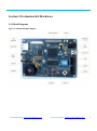
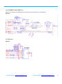
3.5.10 Jumper
Figure 3-12 Jumpers (USB0 Boot Mode Shown)
Table 3-1 Boot mode jumper settings
Boot mode
1
2
3
4
Description
USART0
UP
UP
UP
UP
Boot from device connected to USART0 using pins P2_0 and P2_1.
For flash parts, enter UART ISP mode.
SPIFI
DN
UP
UP
UP
Boot from Quad SPI flash connected to the SPIFI interface on P3_3
to P3_8
EMC 8-bit
UP
DN
UP
UP
Boot from external static memory (such as NOR flash) using CS0
and an 8-bit data bus.
EMC 16-bit
DN
DN
UP
UP
Boot from external static memory (such as NOR flash) using CS0
and a 16-bit data bus.
EMC 32-bit
UP
UP
DN
UP
Boot from external static memory (such as NOR flash) using CS0
and a 32-bit data bus.
USB0
USB1
SPI(SSP)
DN
UP
DN
UP
DN
DN
DN
DN
DN
UP
UP
UP
Boot from USB0.
Boot from USB1.
Boot from SPI flash connected to the SSP0 interface on P3_3
(function SSP0_SCK), P3_6 (function SSP0_MISO), P3_7 (function
SSP0_MOSI), and P3_8 (function SSP0_SSEL).
USART3
DP
DP
DP
DN
Boot from device connected to USART3 using pins P2_3 and P2_4.
For flash parts, enter UART ISP mode.
Sales &Marketing: [email protected]
Technical support: [email protected]
13