1
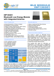
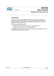
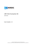
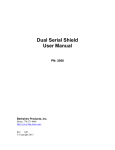
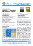
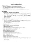
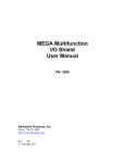
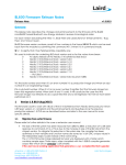
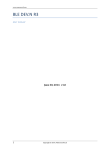
EMRF-nRF51-SKY66111: Bluetooth Low Energy Long Range Arduino Shield Evaluation Kit Description: The EMRF-nRF51-SKY66111 is an Ardiuno shield compatible board that allows a user with the nRF51 DK to plug in the EMRF-nRF51-SKY66111 shield and have a system that provides Long Range capabilities and work with the Nordic SDK examples without any modifications. The shield consists primarily of a nRF51422(BTLE and ANT capable) and a SKY66111-11. The SKY66111-11 is a Power Amplifier(PA) from Skyworks Inc. and provides up to +10dBm output power. This Long Range shield provides an excellent platform for engineers to evaluate the SKY66111-11 in a Long Range application where greater than +4dBm output is desired from the nRF51. The nRF514222 is 100% compatible with the nRF518222 that is BLE only device. Custom Embedded PCB/Software, Wireless/Mobile Applications, and general design services can be provided by Embedded Masters for your own application. Contact [email protected] Want a breakout/evaluation board that Embedded Masters doesn’t currently offer please let us know!! EMRF-nRF51-SKY66111-User Manual 20151021 www.embeddedmasters.com Page 1 References: nRF51422 Product Specification: https://www.nordicsemi.com/eng/nordic/download_resource/20360/9/3824576 nRF51 Reference Manual: http://www.nordicsemi.com/eng/nordic/download_resource/20337/12/15668068 nRF51 SDK Download: http://developer.nordicsemi.com/nRF51_SDK/ nRF51 SDK Documentation/Getting Started: http://infocenter.nordicsemi.com/topic/com.nordic.infocenter.sdk51.v9.0.0/nrf51_getting_started.h tml?c p=4_1_0_1 SKY66111-11: http://store.skyworksinc.com/PortalProductDetail.aspx?ProdId=520726&Ignor eStatus=True BUY IT NOW!! http://www.embeddedmasters.com/ProductDetail/EMRFNRF51SKY66111-Embedded-Masters/574407 Keil Compiler/IDE, FREE 32kB Limited Version: http://www.keil.com/arm/mdk.asp IAR EWARM, FREE 32kB Limited Version: http://supp.iar.com/Download/SW/?item=EWARM-EVAL EMRF-nRF51-SKY66111-User Manual 20151021 www.embeddedmasters.com Page 2 Contents: DESCRIPTION: ............................................................................................................................................................................................................... 1 REFERENCES: ................................................................................................................................................................................................................. 2 CONTENTS:...................................................................................................................................................................................................................... 3 FEATURES:....................................................................................................................................................................................................................... 4 BLOCK DIAGRAM:........................................................................................................................................................................................................ 5 ELECTRICAL CHARACTERISTICS SKY66111-11(ABBREVIATED): .................................................................................................. 6 SKY66111-11 MODE LOGIC TRUTH TABLE.................................................................................................................................................. 7 PIN CONFIGURATIONS AND FUNCTION DESCRIPTIONS: 3.3X3.0X0.8MM 20-PIN MCM PACKAGE ............................. 7 TOP PHOTO: ................................................................................................................................................................................................................... 8 BOTTOM PHOTO: ........................................................................................................................................................................................................ 9 PROGRAMMING/DEBUGGING:.......................................................................................................................................................................... 10 CURRENT MEASUREMENT:................................................................................................................................................................................. 11 RADIO TEST APPLICATION: ......................................................................................................... ERROR! BOOKMARK NOT DEFINED. TRANSMIT CURRENT VS. OUTPUT POWER:.............................................................................................................................................. 22 OUTPUT POWER VS. CHANNEL......................................................................................................................................................................... 23 SPURIOUS EMISSIONS MEASUREMENTS:.................................................................................................................................................... 24 SPURIOUS EMISSIONS PLOTS:........................................................................................................................................................................... 25 SPURIOUS BELOW 1 GHZ, TX MODE, SWEPT CW .................................................................................................................................................................25 0.5*FC SUBHARMONIC, TX, POWER LEVEL 0 .......................................................................................................................................................................25 LO FEEDTHROUGH, SWEPT RX MODE ..................................................................................................................................................................................26 2 ND HARMONIC, TX, POWER LEVEL 0 ...................................................................................................................................................................................26 7 TH HARMONIC, TX, POWER LEVEL 0 ...................................................................................................................................................................................27 8 TH HARMONIC, TX, POWER LEVEL 0 ...................................................................................................................................................................................27 9 TH HARMONIC, TX, POWER LEVEL 0 ...................................................................................................................................................................................28 10 TH HARMONIC, TX, POWER LEVEL 0 .................................................................................................................................................................................28 SCHEMATICS: .............................................................................................................................................................................................................. 29 SKY66111-11 ..................................................................................................................................................................................................................29 NRF51422 CIRCUIT...........................................................................................................................................................................................................30 USB-UART I NTERFACE .....................................................................................................................................................................................................31 NAND LEVEL SHIFTER/I NVERTER CIRCUIT...........................................................................................................................................................................31 CONNECTORS, LEDS, AND SWITCHES ..................................................................................................................................................................................32 EMRF-NRF51-SKY66111 PCB – TOP.............................................................................................................................................................. 33 EMRF-NRF51-SKY66111 PCB – BOTTOM................................................................................................................................................... 33 EMRF-nRF51-SKY66111-User Manual 20151021 www.embeddedmasters.com Page 3 Features: Arduino Shield with nRF51422 and SKY66111-11 compatible out of the box with the Nordic nRF51 DK and Nordic SDK examples. Can be used as Stand-alone without nRF51 if user has JTAG/SWD debugger. 10pin SWD connector is provided on Shield. Nearly +12dBm PA Power output. PA Enable Jumper for testing in PA Bypass Mode. SMA RF Connector for RF analysis. Precisely tuned matching circuit. PCB Antenna Selectable Power Source: CR2032, External Supply, USB, or nRF51 DK 4 Push-Buttons for application use. Header for additional GPIO access. 4 Application LED’s. USB-UART(CP2104) on shield for easy debugging COM terminal interface. Current Measurement header. Makes use of Segger J-LINK debugger/programmer already on nRF51 DK. EMRF-nRF51-SKY66111-User Manual 20151021 www.embeddedmasters.com Page 4 Block Diagram: EMRF-nRF51-SKY66111-User Manual 20151021 www.embeddedmasters.com Page 5 Electrical Characteristics SKY66111-11(abbreviated): (values from SKY66111-11 datasheet for complete specifications please refer to SKY66111-11) Vcc = 3.3V, VBIAS = 1.8V, TA = +25°C, RBIAS = 0kΩ, Characteristic Impedance[Z o] = 50Ω PARAMETER CONDITIONS TYP UNITS DC Characteristics RX Current(bypass) TX quiescent current TX operating current TX bias current(BIAS pin) Sleep current Transmit Characteristics Output Power Saturated gain Gain slope Input return loss Output return loss Third order input intercept point(Note 4) Third order output intercept point(Note 4) RX to TX transition time TX power on time TX power off time Receive Characteristics Isertion Loss Isolation Input return loss Output return loss TX to RX transition time RX power on time RX power off time EMRF-nRF51-SKY66111-User Manual RX mode TX mode TX mode(PIN = -1dBm): VCC = 1.8V VCC = 3.0V VCC = 3.3V 1 6 uA mA 8.5 9.8 10 mA mA mA Sleep Mode 550 0.1 uA uA +8 +10 +10.2 11 0.5 -14 -10 +5 dBm dBm dBm dB dB dB dB dBm +16 dBm 500 ns 500 ns 150 ns 0.9 25 -15 -15 500 dB dB dB dB ns 150 ns 150 ns VCC = 1.8V VCC = 3.0V VCC = 3.3V PIN = -1dBm Over Frequency Range @ 2.44 GHz, ∆f = ± 1 MHz, PIN = 14dBm/tone @ 2.44 GHz, ∆f = ± 1 MHz, PIN = 14dBm/tone 10% to 90% RF 50% VCTX to 90% RF 10% to 90% RF 50% VCTX to 90% RF 10% to 90% RF 50% VCTX to 90% RF 10% to 90% RF 50% VCRX to 90% RF 10% to 90% RF 50% VCRX to 90% RF 10% to 90% RF 50% VCRX to 90% RF 20151021 www.embeddedmasters.com Page 6 SKY66111-11 Mode Logic Truth Table Mode Sleep mode Receive(RX)mode Transmit(TX) mode Non-permissable state(This mode will enable both the TX and RX paths. It is not permittable) CTX 0 0 1 1 CRX 0 1 0 1 Pin Configurations and Function Descriptions: 3.3x3.0x0.8mm 20-pin MCM package Note: Paddle should be connected to GND. EMRF-nRF51-SKY66111-User Manual 20151021 www.embeddedmasters.com Page 7 Top Photo: EMRF-nRF51-SKY66111-User Manual 20151021 www.embeddedmasters.com Page 8 Bottom Photo: EMRF-nRF51-SKY66111-User Manual 20151021 www.embeddedmasters.com Page 9 Programming/Debugging: EMRF-nRF51-SKY66111 is fully functional with or without the nRF51 DK. EMRF-nRF51-SKY66111 can be mounted directly to the nRF51 DK to allow use of the JTAG Programmer/Debugger already on nRF51 DK. Additional 10pin SWD Connector is provided so that EMRF-nRF51SKY66111can be used as a Stand-Alone board also with use of external J-LINK/SWD. EMRF-nRF51-SKY66111-User Manual 20151021 www.embeddedmasters.com Page 10 Current Measurement: Current Measurements can be taken with an Ammeter at jumper J2. Measures TOTAL current to SKY66111 and nRF514222. Nordic Radio Test App can be used to put the nRF51 radio into different modes to allow for current measurements to be taken. EMRF-nRF51-SKY66111-User Manual 20151021 www.embeddedmasters.com Page 11 Getting Started: To get started you can refer to the Quick Start guide from the link below. The information in the Quick Start guide are also provided here along with further details. There are 3 primary firmware examples we will make use of in this section. These examples are all included in the nRF51 SDK, at the time of this document SDK v9.0.0 is the most current. nRF51 SDK v9.0.0 Documentation: http://infocenter.nordicsemi.com/topic/com.nordic.infocenter.sdk51.v9.0.0/index.html?cp=4_1_0 nRF51 SDK Download: http://developer.nordicsemi.com/nRF51_SDK/ 1) Radio Test example: This example provides a simple application that can be used to place the radio into various modes and power levels which are useful for taking RF measurements. http://infocenter.nordicsemi.com/topic/com.nordic.infocenter.sdk51.v9.0.0/nrf_radio_test_exa mple.html?cp=4_1_0_4_6_14 2) Radio Receiver / Radio Transmitter Example: Receiver: http://infocenter.nordicsemi.com/topic/com.nordic.infocenter.sdk51.v9.0.0/nrf_dev_radio_rx_e xample.html?cp=4_1_0_4_6_8 Transmitter: http://infocenter.nordicsemi.com/topic/com.nordic.infocenter.sdk51.v9.0.0/nrf_dev_radio_tx_e xample.html?cp=4_1_0_4_6_9 3) BLE Peripheral / Central Example: First Steps: 1) Plug the EMRF-nRF51-SKY66111 into the nRF51 DK as shown below. 2) Connect the nRF51 DK to your computer with a USB cable. If this is your first time using the nRF51 DK you can also refer to the nRF51 DK User Guide: http://www.nordicsemi.com/eng/nordic/download_resource/38677/1/73523072 EMRF-nRF51-SKY66111-User Manual 20151021 www.embeddedmasters.com Page 12 3) If this is your first usage of the nRF51 DK you will also need to install the nRFgo Studio software(includes JLinkARM, JLink CDC, nRFjprog, and mergehex) from the link below. http://www.nordicsemi.com/eng/Products/2.4GHz-RF/nRFgo-Studio 4) Next you will need to choose your preferred Compiler/IDE: IAR, Keil, or GCC). Links for downloading the FREE 32kB limited versions are included for both IAR and Keil in the Compiler Download section. You will need to register with IAR or KEIL to download the Compiler/IDE. NOTE!! If you already have a previous version of IAR/KEIL you should be able to make use of this. You will most likely need to reconfigure the Project Settings such as Target Device, Header include directories, and Debugger settings as these are typically lost when you open the Project in an older version of the toolset. For those that are already familiar with your respective IDE/Compiler this should be straightforward. a) IAR b) KEIL 5) The next step is to install the nRF51 SDK. At the time of this document the most version was SDK v9.0.0 from the nRF51 SDK Download. EMRF-nRF51-SKY66111-User Manual 20151021 www.embeddedmasters.com Page 13 6) After downloading the SDK Zip file unzip it to a directory where you want to do your firmware development out of. 7) After you have unzipped the SDK you will also see in the top level directory nRF5xMDK_8_0_3_IAR.msi and nRF5xMDK_8_0_3_Keil4.msi installation files. Choose which IDE/Compiler *.msi you prefer to use. This will install the necessary Nordic part specific information into the respective Compiler/IDE that you choose to use. 8) After doing these first simple steps you should be able to compile/run the first example, Radio Test using either Keil or IAR IDE/Compilers. Software Example 1: Radio Test Radio Test Example Instructions: The Receiver and Transmitter project can be found in your SDK Installation directory at the following location. ..\Nordic\examples\peripheral\radio_test Using IAR: 1) Open the ‘radio_test.eww’ project. It should open up in IAR and appear as shown below. EMRF-nRF51-SKY66111-User Manual 20151021 www.embeddedmasters.com Page 14 2) Compile the project by one of two methods. a. Right-click on the Project and select ‘Rebuild All’ b. Click the ‘Make’ Button EMRF-nRF51-SKY66111-User Manual 20151021 www.embeddedmasters.com Page 15 You should now see that the project has compiled… 3) Download/Debug the project on the EMRF-nRF51-SKY66111 board. By either the keyboard shortcut OR the menu. a. Keyboard Shortcut: CTRL+D b. Menu EMRF-nRF51-SKY66111-User Manual 20151021 www.embeddedmasters.com Page 16 4) Using either the USB-UART that comes on the EMRF-nRF51-SKY66111… a. Choose the COM port to connect to using Putty, Hyperterminal, or whatever your preferred Terminal Window is and use the following settings. b. Data Rate: 38400 Data Bits: 8 Parity: None Stop bits: 1 Flow Control: Hardware 5) After you have configured your terminal Window click the ‘GO’ button in the IAR IDE. You now should see the following in your terminal window… EMRF-nRF51-SKY66111-User Manual 20151021 www.embeddedmasters.com Page 17 You can enter various configurations from the terminal window to configure the nRF51 Radio for different modes to perform RF measurements by connecting your RF test equipment to the SMA connector that is supplied on the EMRF-nRF51-SKY66111. NOTE!!! To make use of the SMA connector you will need to ‘De-Pop’ L22 and replace in the L20 position so that the RF output is directed to the SMA connector vs. the PCB Antenna. Using Keil: Using the same procedures you can make use of the KEIL version of these projects by using the following project… radio_test.uvmpw EMRF-nRF51-SKY66111-User Manual 20151021 www.embeddedmasters.com Page 18 Software Example 2: Tx/Rx Communication Example You will need two EMRF-nRF51-SKY66111’s for this Radio Communication example. You only need one nRF51 DK as you can swap the EMRF-nRF51-SKY66111’s onto the nRF51 to be able to program it. This example provides a simple example of configuring one of the boards as a Transmitter and one of the boards as a Receiver. This can be used to do Range Testing. This example is not based on a particular protocol. The Receiver and Transmitter project can be found in your SDK Installation directory at the following location. ..\Nordic\examples\peripheral\radio Using IAR: 1) Open the ‘transmitter.eww’ project. It should open up in IAR and appear as shown below. Radio Transmitter Instructions: 2) Compile the project as shown before and Download/Debug the application. NOTE!!! In IAR if you just want to have the application run in Stand-Alone(without the Debugger) just simply click the Red ‘X’ to disconnect the Debugger. This disconnects the De bugger but the application is still running on the nRF514222 EMRF-nRF51-SKY66111-User Manual 20151021 www.embeddedmasters.com Page 19 3) Next we need to program the second EMRF-nRF51-SKY66111as the Receiver. You can either open up another instance of IAR or simply open the Receiver project in the same instance of IAR. If you want to inspect the source code of both the Receiver and the Transmitter it is useful to have 2 instances of IAR running concurrently. Open the ‘receiver.eww’ project. Radio Receiver Instructions: 4) If ‘receiver_pca10028 – nRF51422_xxac’ is not HIGHLIGHTED as shown above you will need to right click on this project and choose ‘Set As Active’. 5) As before compile, download/debug. 6) We now have a EMRF-nRF51-SKY66111 programmed as a Transmitter and one as a Receiver. 7) To test the radio communications the easiest way is to put a CR2032 into the ‘Transmitter’ board and leave the ‘Receiver’ board connected to a PC so you can see that the signal from the Transmitter has been received. a. Connect the Receiver board to a PC using the USB-UART on the EMRF-nRF51-SKY66111 configure a Terminal Window program such as Putty, Hyperterminal, etc and configure as we have done in the Radio Test with the following settings. b. Data Rate: 38400 Data Bits: 8 Parity: None Stop bits: 1 Flow Control: Hardware c. You can use the Transmitter board as a stand-alone board by inserting a CR2032 into the Coin Cell holder on the bottom of the board. NOTE!!! Unfortunately you will need to carefully bend up the edges of the COIN CELL HOLDER on this version to be able to insert the COIN CELL. APPLY DOWNWARD PRESSURE ON THE COIN CELL HOLDER WHILE GENTLY APPLY UPWARDS PRESSURE ON THE ROUNDED (+) TABS TO BEND THEM UPWARDS. DOWNWARD PRESSURE WITH YOUR HAND ON THE COIN CELL HOLDER IS HIGHLY RECOMMEND TO AVOID PULLING THE PAD OFF THE PCB. WE APOLOGIZE FOR THIS INCONVENIENCE AND WILL BE FIXED IN A FUTURE VERSION. EMRF-nRF51-SKY66111-User Manual 20151021 www.embeddedmasters.com Page 20 d. Now you can press any of the pushbuttons SW2-SW5 on the transmitter board and you will see the output on the Terminal Window that is connected to the Receiver board as shown below. Each button has a distinct message that is printed. Using KEIL: Using the same procedures you can make use of the KEIL version of these projects by using the following projects… transmitter.uvmpw receiver.uvmpw EMRF-nRF51-SKY66111-User Manual 20151021 www.embeddedmasters.com Page 21 Transmit Current vs. Output Power: Approximately 1.5mA current advantage around +4dBm. Nearly +12dBm output power available. EMRF-nRF51-SKY66111-User Manual 20151021 www.embeddedmasters.com Page 22 Output Power vs. Channel Power Levels Correspond to Power Settings using the ‘Radio Test’ Example in the nRF51 SDK. Power level 0 = +4dBm, Power level 1 = 0dBm, Power level 2 = -4dBm, Power level 3 = -8dBm Power level 4 = -12dBm, Power level 5 = -16dBm, Power level 6 = -20dBm, Power level 7 = -30dBm SKY66111 provides 8dB of TX gain with the supplied BOM. 1 dB or better flatness across BTLE band at all power levels except max. Up to +12dBm output power available. EMRF-nRF51-SKY66111-User Manual 20151021 www.embeddedmasters.com Page 23 Spurious Emissions Measurements: All spurious emissions are measured at maximum output power(+12dBm, power level 0), with the EMRF-nRF51-SKY66111 powered from USB. For TX mode spurious emissions the nRF51 generates a CW signal swept across the BTLE band; RX mode spurious emissions are caused by sweeping the Local Oscillator(LO). Emissions were measured using an FSQ-26 spectrum analyzer connected to the SMA test port. MAX HOLD(300 sweeps) Peak Detector VBW 1MHz, RBW 3 MHz All spurious emissions comply with FCC limits(conducted at test port). EMRF-nRF51-SKY66111-User Manual 20151021 www.embeddedmasters.com Page 24 Spurious Emissions Plots: Spurious below 1 GHz, Tx mode, swept CW 0.5*Fc subharmonic, TX, power level 0 EMRF-nRF51-SKY66111-User Manual 20151021 www.embeddedmasters.com Page 25 LO feedthrough, swept RX mode 2nd Harmonic, TX, power level 0 EMRF-nRF51-SKY66111-User Manual 20151021 www.embeddedmasters.com Page 26 7th Harmonic, TX, power level 0 8th Harmonic, TX, power level 0 EMRF-nRF51-SKY66111-User Manual 20151021 www.embeddedmasters.com Page 27 9th Harmonic, TX, power level 0 10th Harmonic, TX, power level 0 EMRF-nRF51-SKY66111-User Manual 20151021 www.embeddedmasters.com Page 28 Schematics: SKY66111-11 Resistor R16 trades off Icc for Tx gain; 12kΩ gives ~8dB. Output filter tuned to remove harmonics and subharmonics. L22/L20 inductor placement selects SMA connector or PCB trace antenna. EMRF-nRF51-SKY66111-User Manual 20151021 www.embeddedmasters.com Page 29 nRF51422 Circuit Output match (C12, L6, C10) retuned due to ground slot removal. Inductor placements(L4, L5) allow DC-DC mode operation. SMT placements allow use of P0.27 and P0.26 for GPIO(instead of XTAL). EMRF-nRF51-SKY66111-User Manual 20151021 www.embeddedmasters.com Page 30 USB-UART Interface CP2104 USB-UART bridge provides VCP interface and can also power EMRF-nRF51-SKY66111 from its 3.45V output. NAND Level Shifter/Inverter Circuit Level Translating NAND gates provide direct nRF51 DK compatibility. Gates toggle SKY66111, CRX and CTX, from nRF51422 PA supply. User can drive CRX/CTX directly from P0.22, P0.21 respectively with firmware modification. EMRF-nRF51-SKY66111-User Manual 20151021 www.embeddedmasters.com Page 31 Connectors, LEDs, and Switches Top connectors have Arduino pinout(P1, P2, P3, P4). Power Options: nRF51 DK Arduino Micro-USB Cable DC Supply CR2032 Coin Cell Programmable by nRF51 DK External ARM SWD Programmer/Debugger via 10pin SWD connector, P18. EMRF-nRF51-SKY66111-User Manual 20151021 www.embeddedmasters.com Page 32 EMRF-nRF51-SKY66111 PCB – Top ADD PCB PICTURES!! EMRF-nRF51-SKY66111 PCB – Bottom ADD PCB BOTTOM PICTURES!! EMRF-nRF51-SKY66111-User Manual 20151021 www.embeddedmasters.com Page 33