1
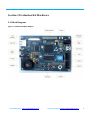
(3) JTAG Debugger Connection: One end is connected to JTAG interface on the board (J9), the other to PC . (4) Turn on the switch (SW2). (5) U Stick: prepare a U stick. (6) Turn on the switch. (7) Build the project, and download the image to the board, as chapter 4.1.2. Phenomenon: (1) Create a .txt file, named 1. You can write anything in this file, save it and put it in the U Stick. Here I write as below: (2) Reset the board. After the PC realize the virtual COM, open your terminal, configured as below: Baud rate: 9600 Data bit: 8bits Stop bit: 1bit Check bit: none Data flow control: none Insert the U stick to the USB Host interface (J4). The terminal will show what you’ve written in the 1.txt file, as below: 4.10 SDRAM Location: LPC4357-EVB\Examples\02-SDRAM The project describes how to read and write the SD card. Preparation: (1) Power support: power line (J8) connection. (2) USB device connection: connect the board to the computer through the USB device interface (J7). (3) JTAG Debugger Connection: One end is connected to JTAG interface on the board (J9), the other to PC . (4) Turn on the switch (SW2). Sales &Marketing: [email protected] Technical support: [email protected] 29