1
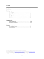
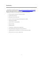
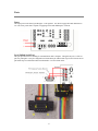
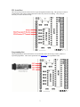
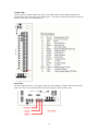
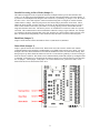
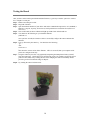
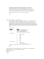
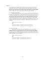
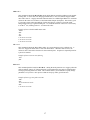
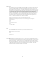
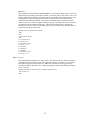
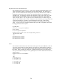
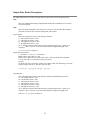
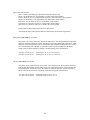
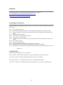
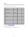
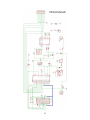
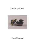
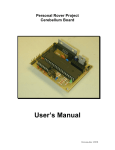
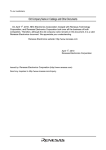
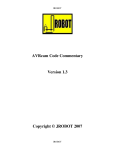
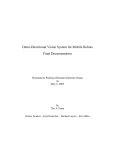
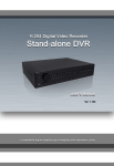
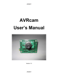
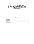
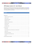
CMUcam Vision Board
User Manual
Contents
Introduction ………………………………………………………. 3
Hardware
Board Layout …………………………………………….. 4
Assembled View ………………………………………….. 5
Ports and Jumpers ………………………………………… 6-9
Testing ……………………………………………………. 10
About the Camera ………………………………………… 11
Parts list …………………………………………………… 24
Schematic …………………………………………………. 25
Communication
Serial Command Set ……………………………………… 12-20
Data Packet Description ………………………………….. 21-22
Firmware
Downloading Firmware …………………………………... 23
Troubleshooting …………………………………………. 23
This is the CMUcam Manual v1.08 for the CMUcam v1.1 firmware.
For more information go to http://www.cs.cmu.edu/~cmucam or contact us at [email protected]
Copyright 2001 Anthony Rowe and Carnegie Mellon University. All Rights Reserved.
2
Introduction
The CMUcam is a SX28 microcontroller ( http://www.ubicom.com/products/processors/sx28ac.html )
interfaced with an OV6620 Omnivision CMOS camera (http://www.ovt.com/omnicmoss.htm) on a chip
that allows simple high level data to be extracted from the camera’s streaming video. The board
communicates via a RS-232 or a TTL serial port and has the following functionality:
•
Track user defined color blobs at 17 Frames Per Second
•
Find the centroid of the blob
•
Gather mean color and variance data
•
Transfer a real-time binary bitmap of the tracked pixels in an image
•
Arbitrary image windowing
•
Adjust the camera' s image properties
•
Dump a raw image
•
80x143 Resolution
•
115,200 baud or 38,400 baud serial communication
•
Slave parallel image processing mode off a single camera bus
•
Automatically detect a color and drive a servo to track an object upon startup
•
Ability to control 1 servo or have 1 digital I/O pin
3
Board Layout
4
Assembled View
5
Ports
Power
The input power to the board goes through a 5 volt regulator. It is ideal to supply the board with between
5-6 volts of DC power that is capable of supplying at least 200 milliamperes of current.
Level Shifted Serial Port
This port provides full level shifting for communication with a computer. Though it only uses 3 of the 10
pins it is packaged in a 2x5 pin configuration to fit standard 9 pin ribbon cable clip-on serial sockets and 10
pin female clip on serial headers that can both attach to a 10 wire ribbon cable.
6
TTL Serial Port
This serial port taps into the serial I/O before it goes through the MAX232 chip. This port may be ideal for
communication with a microcontroller that does not have any built in level shifting. Note, it may be
necessary to remove the max232 chip.
Programming Port
The programming port allows the firmware to be downloaded to the SX28 using a SX-Key / Blitzer or
equivalent programmer. These can be purchased from Parallax Inc (www.parallaxinc.com).
7
Camera Bus
This bus interfaces with the CMOS camera chip. The CMOS camera board is mounted parallel to the
processing part of the board and connects staring at pin 1. The female camera header should be soldered on
the back of the board. (See assembled view)
Servo Port
This is the output for the servo. The positive signal does not go through a regulator from the boards power
input. Do not use a servo with the board if the board is being run off of more than 6 volts.
8
Parallel Processing in Slave Mode (Jumper 1)
The CMUcam supports a mode of operation that allows multiple boards to process data from the same
camera. If a PC104 style pass through header is used instead of the standard double row female header, it
is possible to rack multiple boards along the same camera bus. Upon startup, if jumper 1 is set, the camera
becomes a slave. Slave mode stops the camera board from being able to configure or interfere with the
CMOS camera’s settings. Instead it just processes the format setup by the master vision board. When
linking the buses together you must only have one master, all other boards should be setup to be in slave
mode. In this current version of the system there is no message passing between boards other than the
image data from the camera bus. This means you have to communicate to each slave board via a separate
serial link. This communication to the board should be identical to using a single CMUcam. For example,
you could have the master board tracking some color while the slave board could be told to get mean color
data. Each board runs independently of one another and only the master can control camera registers.
Baud Rate (Jumper 2)
Jumper 2 on the camera switches the baud rate from 115,200 baud to 38,400 baud.
Demo Mode (Jumper 3)
Jumper 3 puts the camera into a demo mode. Demo mode causes the camera to call the track window
command and then begin outputting a standard hobby servo PWM signal from the servo output. The servo
attempts to drive the camera mounted on it towards the middle mass of the color detected on startup. Note
that upon power up in this mode the camera will wait for 5 seconds before grabbing a color and servoing to
allow the camera to stabilize. This feature can be enabled manually without the jumper by sending the MM
2 command. If when the servo is mounted on the camera it appears to be tracking in the incorrect direction
also set jumper 1. When jumper 1 and jumper 3 are set, the board does not go into slave mode, it runs
demo mode and reverses the direction of the servo.
9
Testing the Board
Once you have set the board up and downloaded the firmware, a good way to test the system is to connect
it to a computer’s serial port.
Step 1: Build a serial and power cable.
Step 2: Plug both of them in.
Step 3: Open the terminal emulator of your choice and set the communication protocol to 115,200 Baud, 8
Data bits, 1 Stop bit, no parity, local echo on, and if possible turn on "add line feed" (add \n to a
received \r).
Step 4: Turn on the board, the Power LED should light up and the Track LED should not.
Step 5: You should see the following on your terminal emulator:
CMUcam v1.1
:
Once you have seen this, the board was able to successfully configure the camera and start the
firmware.
Step 6: Type gv followed by the enter key. You should see the following:
:gv
ACK
CMUcam v1.1
:
This shows the current version of the firmware. If this is successful, then your computer serial
port is also configured correctly.
Step 7: Using the CMUcam java GUI or by graphically interpreting the Dump Frame Packet yourself,
focus the camera lens. Usually the lens is focused when it sits a few rotations out from its closest
position to the CMOS array. Turning the lens and re-dumping the frame incrementally should
provide a good feel for when the image is sharpest.
Step 8: Try running the camera in demo mode.
10
About the Camera
From power up, the camera can take up to 6 seconds to automatically adjust to the light. Drastic changes in
the environment, such as lights being turned on and off, can induce a similar readjustment time. When
using the camera outside, due to the sun’s powerful IR emissions, even on relatively cloudy days it will
probably be necessary to use either an IR filter or a neutral density 3 camera filter to decrease the ambient
light level. The field of view depends on the lens attached to the camera. Amazon Electronics provides a
f3.7mm, F2.0 lens with a 65deg x 50deg field of view. It is possible to special order the camera with wider
or narrower lenses. Individual lenses can be purchased separately.
The functions provided by the camera board a meant to give the user a toolbox of color vision functions.
Actual applications may greatly vary and are left up to the imagination of the user. Being able to change
the viewable window, grab color / light statistics and track colors can be interwoven by the host processor
to create higher level functionality.
11
Serial Command Set
The serial communication parameters are as follows:
•
115,200 Baud
•
8 Data bits
•
1 Stop bit
•
No Parity
•
No Flow Control (Not Xon/Xoff or Hardware)
All commands are sent using visible ASCII characters (123 is 3 bytes "123" ). Upon a successful
transmission of a command, the ACK string should be returned. If there was a problem in the syntax of the
transmission, or if a detectable transfer error occurred a NCK string is returned. After either an ACK or a
NCK, a \r is returned. When a prompt ('\r' followed by a ':' ) is returned, this indicates that the camera is
waiting for another command in the idle state. White spaces do matter and are used to separate argument
parameters. The \r (ASCII 13 carriage return) is used to end each line and activate each command. If
visible character transmission exerts too much overhead, it is possible to use varying degrees of raw data
transfer. (See Raw Mode)
12
\r
This command is used to set the camera board into an idle state. Like all other
commands you should receive the acknowledgment string "ACK” or the not
acknowledge string "NCK" on failure. After acknowledging the idle command the
camera board waits for further commands which is shown by the ':' prompt. While in this
idle state a /r by itself will return an "ACK" followed by \r and : character prompt.
Example of how to check if the camera is alive while in the idle state
:
ACK
:
CR [ reg1 value1 [reg2 value2 ... reg16 value16] ]\r
This command sets the Camera's internal Register values directly. The register locations and
possible settings can be found in the Omnivision documentation. All the data sent to this
command should be in decimal visible character form unless the camera has previously been set
into raw mode. It is possible to send up to 16 register-value combinations. Previous register
settings are not reset between CR calls, however you may overwrite previous settings. Calling this
command with no arguments resets the camera and restores the camera registers to their default
state.
Useful Settings:
Register
18 Color Mode
Values
36 YCrCb* Auto White Balance On
32 YCrCb* Auto White Balance Off
44 RGB Auto White Balance On
40 RGB Auto White Balance Off (default)
17 Clock Speed
2
3
4
5
6
7
8
10
12
17 fps (default)
13 fps
11 fps
9 fps
8 fps
7 fps
6 fps
5 fps
4 fps
32
33
Auto Gain Off
Auto Gain On (default)
19 Auto Exposure
Example of decreasing the internal camera clock speed (default speed is 2)
:CR 17 5
ACK
:
*Red channel becomes Cr which approximates r-g, Green channel becomes Y which approximates
intensity, Blue channel becomes Cb which approximates b-g
RGB -> CrYCb
Y=0.59G + 0.31R + 0.11B
Cr=R-Y
Cb=B-Y
13
DF\r
This command will Dump a Frame out the serial port to a computer. This is the only
command that will by default only return a non-visible ASCII character packet. It dumps
a type F packet that consists of the raw video data column by column with a frame
synchronize byte and a column synchronize byte. (This data can be read and displayed
by the CMUcamGUI java application. ) Since the data rate required to send the raw video
greatly exceeds the maximum serial port speed, only one column per frame is sent at a
time. This allows you to see a slowly updating view of what the camera sees. To get the
correct aspect ratio, double each column of pixels.
Type F data packet format
1 - new frame
2 - new col
3 - end of frame
RGB (CrYCb) ranges from 16 - 240
1 2 r g b r g b ... r g b r g b 2 r g b r g b r ... r g b r g b ...
Example of a Frame Dump from a terminal program
(WARNING: This may temporarily interfere with a terminal program by sending non
visible characters)
:DF
ACK
maKP(U A$IU AL<>U A$L*YL%*L L (G AUsonthAYA(KMAy098a34ymawvk....
GM\r
This command will Get the Mean color value in the current image. As with the TC
command this function only operates on a selected region of the image. The mean
values will be between 16 and 240. It will also return a measure of the average absolute
deviation of color found in that region. The mean together with the deviation can be a
useful tool for automated tracking or detecting change in a scene. In YCrCb mode RGB
maps to CrYCb.
Type S data packet format
S Rmean Gmean Bmean Rdeviation Gdeviation Bdeviation\r
Example of how to grab the mean color of the entire window
:SW 1 1 40 143
ACK
:GM
ACK
S 89 90 67 5 6 3
S 89 91 67 5 6 2
S 88 90 66 4 6 2
GV\r
This command Gets the current Version of the firmware from the camera. It returns an
ACK followed by the firmware version string.
Example of how to ask for the firmware version
:GV
ACK
CMUcam v1.0
14
HM active\r
This command puts the camera into Half-horizontal resolution Mode for the DF command and the
LM command when dumping a bitmap image. An acitve value of 1 causes only every odd column
to be processed. The default value of 0 disables the mode.
I1 \r
This command uses the servo port as a digital Input. Calling I1 returns either a 1 or 0 depending
on the current voltage level of the servo line. The line is pulled high, so it is only required to pull
it low or let it float to change its state. The servo line can also be used as a digital output. ( See S1
command)
Example of how to read the digital value of the servo line
:I1
ACK
1
L1 value\r
This command is used to control the tracking Light. It accepts 0, 1 and 2 (default) as inputs. 0
disables the tracking light while a value of 1 turns on the tracking light. A value of 2 puts the light
into its default auto mode. In auto mode and while tracking, the light turns on when it detects the
presents of an object that falls within the current tracking threshold. This command is useful as a
debugging tool.
Example of how to toggle the Tracking Light on and then off
:L1 2
ACK
:L1 0
ACK
15
LM active\r
This command turns on Line Mode which uses the time between each frame to transmit more
detailed data about the image. It adds prefix data onto either C, M or S packets. This mode is
intended for users who wish to do more complex image processing on less reduced data. Since the
frame rate is not compromised, the actual processing of the data output by the vision system must
be done at a higher rate. This may not be suitable for many slower microcontrollers.
Line mode’s effect on TC and TW:
When line mode is active and TC or TW is called, line mode will send a binary bitmap of
the image as it is being processed. It will start this bitmap with an 0xAA flag value (hex value AA
not in human readable form). The value 0xAA will not occur in the data stream. This is followed
by bytes each of which contains the binary value of 8 pixels being streamed from the top-left to
the bottom-right of the image. The vertical resolution is constrained by the time in which it takes
to transfer the horizontal data so lines may be skipped when outputting data. In full resolution
mode, the resulting binary image is 80x48. The binary bitmap is terminated by two 0xAA’s. This
is then followed by the normally expected standard C or M data packet (processed at that lower
resolution).
Example of TC with line mode on
:LM 1
:TC
(raw data: AA XX XX XX …. XX XX XX AA AA) C 45 72 65 106 18 51
(raw data: AA XX XX XX …. XX XX XX AA AA) C 46 72 65 106 18 52
Line mode’s effect on GM:
When line mode is active and GM is called, line mode will send a raw (not human
readable) mean value of every line being processed. These packets are started with an 0xFE and
terminate with an 0xFD. Each byte of data between these values represents the corresponding
line’s mean color value. Similarly to the bitmap mode, due to the serial transfer time the vertical
resolution is halved. At 17 fps 115,200 baud every other line is skipped. At any slower frame rate
(still 115,200 baud) no lines will be skipped.
Example of GM with line mode on
:LM 1
:GM
(raw data: FE XX XX XX … XX XX XX FD) M 45 56 34 10 15 8
(raw data: FE XX XX XX … XX XX XX FD) M 45 56 34 10 15 8
16
MM mode\r
This command controls the Middle Mass mode which adds the centroid coordinates to the normal
tracking data. A mode value of 0 disengages middle mass, a value of 1(default) engages middle
mass and a value of 2 engages the mode and turns on the servo PWM signal that tries to center the
camera on the center of color mass (see the Demo Mode Jumper description). This mode is good
if you want a single point representation of where the object is or if there is too much small
background noise to get a good bounding box. To switch the direction of the servo it is necessary
to set the 2nd bit (counting from 0 i.e. 4) of the mode value.
Example of how to disable Middle Mass mode
:MM 0
ACK
:TC
ACK
C 38 82 53 128 35 98
C 38 82 53 128 35 98
C 38 82 53 128 35 98
NF active\r
This command controls the Noise Filter setting. It accepts a Boolean value 1 (default) or 0. A
value of 1 engages the mode while a value of 0 deactivates it. When the mode is active, the
camera is more conservative about how it selects tracked pixels. It requires 2 sequential pixels for
a pixel to be tracked.
Example of how to turn on noise filtering
:NF 1
ACK
:
PM mode\r
This command puts the board into Poll Mode. Setting the mode parameter to 1 engages poll mode
while 0 (default) turns it off. When poll mode is engaged then only one packet is returned when
an image processing function is called. This could be useful if you would like to rapidly change
parameters or if you have a slow processor that can't keep up with a given frame rate.
Example of how to get one packet at a time
:PM 1
ACK
:TC 50 20 90 130 70 255
ACK
C 38 82 53 128 35 98
:
17
RM bit_flags\r
This command is used to engage the Raw serial transfer Mode. It reads the bit values of the fist 3
(lsb) bits to configure settings. All bits cleared is the default visible ascii mode. If bit 0 is set,
then all output is in raw byte packets. The format of the data packets will be changed so as not to
include spaces or be formatted as readable ASCII text. Instead you will receive a 255 valued byte
at the beginning of each packet followed by the packet including the packet identifying character
(i.e. C for a color packet). There is no \r sent after each packet, so you must use the 255 to
synchronize the incoming data. Any 255 valued bytes that may be sent as part of the packet are
set to 254 to avoid confusion. If bit 1 is set then all input will be read as raw byte values too.
After the byte values of a command are sent, send 1 byte telling how many arguments are to
follow. (i.e. DF0 for no arguments) No \r character is required.
Example of the new packet for Track Color with Raw Mode output only
(WARNING: This may temporarily interfere with a terminal program by sending non
visible characters)
:RM 1
ACK
:TC 50 20 90 130 70 255
ACK
C>%k(ai Ck$&,.L
RS \r
This command ReSets the vision board. Note, on reset the first character is a /r.
Example of how to reset the camera
:rs
ACK
CMUcam v1.0
:
S1 position \r
This command lets you Set the position of servo 1. 0 turns the servo off and holds the line low. 1127 will set the servo to that position while it is tracking or getting mean data. Any value 128 and
higher sets the line high. In order for the servo to work, the camera must be in either a tracking
loop or mean data gather loop. Values 0 and 128 can be useful if you wish to use the servo port as
a digital output. The port can also be used as a digital input (see I1 command). The “MM”
command can enable or disable the automatic servo tracking.
18
SM value \r
This command is used to enable the Switching Mode of color tracking. When given a 0 it is in it's
default mode where tracking will return its normal C or M color packet. If the value is set to 1, the
tracking commands will alternate each frame between color packets and S statistic packets. Each
statistic packet is only being sampled from an area one quarter the size of the bounded area
returned from the tracking command. If no object was bounded, then no S statistic packets are
returned. This can be useful for adaptive tracking or any type of tracking where you would like to
get feedback from the currently bound target. After the first tracking packet is returned, the
window gets set back to full size for all future packets. Note, you will get only half the number of
actual color packets per time interval.
Example of how to Track Color with SM
:SM 1
ACK
:TC 200 255 0 30 0 30
ACK
C 2 40 12 60 10 70
S 225 20 16 2 3 1
C 5 60 20 30 12 100
S 225 19 17 1 2 1
C000000
C000000
C000000
C 5 60 20 30 12 100
S 225 19 17 1 2 1
SW [x y x2 y2] \r
This command Sets the Window size of the camera. It accepts the x and y Cartesian coordinates
of the upper left corner followed by the lower right of the window you wish to set. The origin is
located at the upper left of the field of view. SW can be called before an image processing
command to constrain the field of view. Without arguments it returns to the default full window
size of 1,1,80,143.
Example of setting the camera to select a mid portion of the view
:SW 35 65 45 75
ACK
:
19
TC [Rmin Rmax Gmin Gmax Bmin Bmax]\r
This command begins to Track a Color . It takes in the minimum and maximum RGB (CrYCb)
values and outputs a type M or C data packet (set by the MM command). The smaller type C
packet encodes a bounded box that contains pixels of the curently defined color, the number of
found pixels (scaled: actual value is (pixels+4)/8 ) that fall in the given color bounds and a
confidence ratio. The default type M packet also includes the center of mass of the object. The
resolution of the processed image is 80x143. The X values will range from 1 to 80 and the y
values will range from 1 to 143. A packet of all zeros indicates that no color in that range was
detected. The confidence value is a ratio of the pixels counted within the given range and the area
of the color bounding box. It returns a value which ranges from 0 to 255. Under normal
operations any value greater then 50 should be considered a very confident lock on a single
object. A value of 8 or lower should be considered quite poor. With no arguments, the last color
tracking parameters will be repeated.
Type M packet
M mx my x1 y1 x2 y2 pixels confidence\r
Type C packet
C x1 y1 x2 y2 pixels confidence\r
Example of how to Track a Color with the default mode parameters
:TC 130 255 0 0 30 30
ACK
M 50 80 38 82 53 128 35 98
M 52 81 38 82 53 128 35 98
M 51 80 38 82 53 128 35 98
TW \r
This command will Track the color found in the central region of the current Window. After the
color in the current window is grabbed, the track color function is called with those parameters
and on the full screen. This can be useful for locking onto and tracking an object held in front of
the camera. Since it actually calls track color, it returns the same type of C or M color packet.
Note, your set window will only be used for grabbing the color to track and then the window will
return to 80x143.
Example of how to use Track Window:
:TW
ACK
S 240 50 40 12 7 8
C 2 40 12 60 10 70
C 3 41 12 61 11 70
C 2 40 12 60 13 70
C 3 42 12 62 9 70
C 4 45 12 60 8 70
20
Output Data Packet Descriptions
All output data packets are in ASCII viewable format except for the F frame and prefix packets.
ACK
This is the standard acknowledge string that indicates that the command was received and
fits a known format.
NCK
This is the failure string that is sent when an error occurred. The only time this should be
sent when an error has not occurred is during binary data packets.
Type C packet
This is the return packet from a color tracking command.
x1 - The left most corner's x value
y1 - The left most corner's y value
x2 - The right most corner's x value
y2 -The right most corner's y value
pixels –Number of Pixels in the tracked region, scaled and capped at 255: (pixels+4)/8
confidence -The (# of pixels / area)*256 of the bounded rectangle and capped at 255
C x1 y1 x2 y2 pixels confidence\r
Type F data packet format
1 - new frame 2 - new col 3 - end of frame
RGB (CrYCb) ranges from 16 - 240
RGB (CrYCb) represents a two pixels color values. Each pixel shares the red and blue.
176 cols of R G B (Cr Y Cb) packets (forms 352 pixels)
144 rows
To display the correct aspect ratio, double each column so that your final image is 352x144
It does not begin with an “F” and only sends raw data!
1 2 r g b r g b ... r g b r g b 2 r g b r g b ... r g b r g b ...
Type M packet
This is the return packet from a color tracking command with Middle Mass mode on.
mx - The middle of mass x value
my - The middle of mass y value
x1 - The left most corner's x value
y1 - The left most corner's y value
x2 - The right most corner's x value
y2 -The right most corner's y value
pixels –Number of Pixels in the tracked region, scaled and capped at 255: (pixels+4)/8
confidence -The (# of pixels / area)*256 of the bounded rectangle and capped at 255
M mx my x1 y1 x2 y2 pixels confidence\r
21
Type S data packet format
This is a statistic packet that gives information about the camera's view
Rmean - the mean Red or Cr (approximates r-g) value in the current window
Gmean - the mean Green or Y (approximates intensity) value found in the current window
Bmean - the mean Blue or Cb (approximates b-g) found in the current window
Rdeviation - the *deviation of red or Cr found in the current window
Gdeviation- the *deviation of green or Y found in the current window
Bdeviation- the *deviation of blue or Cb found in the current window
S Rmean Gmean Bmean Rdeviation Gdeviation Bdeviation\r
*deviation: The mean of the absolute difference between the pixels and the region mean.
Binary bitmap Line Mode prefix packet
This packet is in raw byte form only. It starts off with the hex value 0xAA and then streams bytes,
each byte containing a mask for 8 pixels, from the top-left to the bottom-right of the image. (Each
binary bit in the byte represents a pixel) The bitmap is then terminated with two 0xAAs. 0xAA is
never transmitted as part of the data, so it should be used to signify termination of the binary
bitmap. After the binary bitmap is complete, a normal tracking packet should follow.
(raw data: AA XX XX XX …. XX XX XX AA AA) C 45 72 65 106 18 51
(raw data: AA XX XX XX …. XX XX XX AA AA) C 46 72 65 106 18 52
Get mean Line Mode prefix packet
This packet prefix outputs the mean color of each row being processed. These packets are started
with an 0xFE and terminate with an 0xFD. Each byte of data between these values represents the
corresponding line’s mean color value. Due to the serial transfer time, the vertical resolution is
halved. After all rows have been completed, a normal tracking packet should follow.
(raw data: FE XX XX XX … XX XX XX FD) M 45 56 34 10 15 8
(raw data: FE XX XX XX … XX XX XX FD) M 45 56 34 10 15 8
22
Firmware
Once the board has been assembled and powered up, the firmware can be downloaded using the SX-Key
downloading program. The SX-Key downloader and manual are available at:
www.parallaxinc.com/html_files/downloads/downloads_sx.htm
The firmware for the camera can be found at:
http://www.cs.cmu.edu/~cmucam/downloads.html
Downloading The Firmware
After downloading and installing the SX-Key software, it is necessary to load the CMUcam.hex firmware
to the board.
step 1: Turn on the boards power.
step 2: Ensure that the programming switch is in the program mode (pushed away from the LEDs)
step 3: Plug in the SX-key text side facing away from the board. (for more details see the hardware port
section)
step 4: Open up the SX-Key software
step 5: Select "Device" from under the "Run" menu
step 6: Click on the "Load Hex" button
step 7: Go to the directory of the CMUcam.hex file and type its name into the dialog box. (It may not be
visible)
step 8: Press "Open" to load it
step 9: Press the "Program" button
step 10: Once programming has finished, turn off the power to the board
step 11: Unplug the SX-Key and switch the programming switch into the run position
step 12: Once the power switch is turned on again the firmware should be running and will greet you with
CMUcam v1.1
:
Troubleshooting
If when you tried to program you see or experience:
SX-Key not found -Make sure the comm port is set correctly and power is going to the camera
Vpp Generation Failed -Ensure that the program switch is in the correct position
Programming Failed - Try it again and if it still occurs consult the SX-Key manual
No response - Make sure you switched the board out of program mode. Try power cycling the board.
23
Hardware
The following is a list of parts needed to assemble the CMUcam.
Qty
1
1
1
1
1
3
2
6
2
1
1
2
3
2
1
1
1
1
(1)
(2)
(1)
(1)
(1)
Item
75 MIPS Ubicom SX28
OV6620 Eval Board *
Maxim 232 Level Shifter
SG-531 75.00 MHz crystal osc
5 Volt Regulator
4.7 Kohm 1/4 Watt Resistor
220 ohm 1/4 Watt Resistor
1.0 uF Capacitor
SPST Switch
3mm red LED
3mm green LED
0.1uF Capacitor
100 uF Capacitor
14 pin IC socket (to form a 28 pin socket)
8 pin IC socket **
16 pin IC socket
Double row female header
Single row male header
Polarized 2 pin terminal housing
Crimp terminals
Polarized 2 pin terminal header
Female serial ribbon cable head
Serial ribbon cable socket connector
Part no. (Digi-key)
SX28AC75/DP-ND
BB048*
MAX232CPE-ND
SE2911-ND
LM2940CT-5.0-ND
4.7KQBK-ND
220QBK-ND
P2105-ND
EG1847-ND
67-1125-ND
67-1127-ND
P4923-ND
P5138-ND
AE8914-ND
ED3308-ND
ED3316-ND
929852-01-36
929647-09-36-ND
WM2700-ND
WM2200-ND
WM4000-ND
AFS09G-ND
ASC10G-ND
Schematic Label
IC1
Unit Price
5.18
57.95
IC3
3.31
QG1
5.85
IC2
1.80
R2 R3 R4
0.06
R1
0.06
C1 C2 C3 C4 C5 C6 0.42
S1 S2
1.11
LED3MM
0.16
D1
0.16
C8 C10
0.55
C7 C9 C11
0.28
IC1
0.32
QG1
0.42
IC3
0.83
JP5
3.35
JP1x2 JP3 JP4 JP7 1.83
0.25
0.13
0.25
6.14
1.11
*Order Code BB048 at http://www.electronics123.com. Ask them for an evaluation board with an OV6620
from Omnivision and an IR coated lens.
**Use this for the oscillator by cutting off the inner 4 legs
( ) accessories that make interfacing easier, but are not required for functionality
24
25