1
Seattle Robotics
CMUcam1 AppMod Vision System
TM
for
BoeBot
User Guide
This product or portions thereof is manufactured under license from Carnegie Mellon University.
AppMod is a trademark of Parallax, Inc.
Copyright 2004 Seattle Robotics. All Rights Reserved.
User Guide version 1.0
The CMUcam1 AppMod vision system
The goal of this product is to give you as simple a plug-n-play experience as possible.
Plug in the hardware, upload the demo code then press the buttons and watch your BoeBot use it’s new
vision system to “see” and respond to it’s environment.
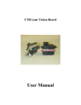
The CMUcam1 AppMod vision system consists of a CMUcam1 vision system mounted on a plug in
AppMod board.
Included on the AppMod board is a simple user interface consisting of two buttons, eight LED’s and one
piezo speaker. The user interface serves these three purposes –
1) A simple menu selection system which works with the included demo code to allow you to select and
run one of eight robot vision demonstration programs.
2) Provide visual feedback from the LED’s as the demo programs run showing where the CMUcam1 is
seeing the tracked target.
3) Indicate the color of objects it see’s by illuminating the red leds for a red object, green led’s for a green
object and yellow led’s for a yellow object.
With some clever circuitry on the AppMod board the two buttons, eight led’s and one piezo speaker only
require four I/O pins on your Basic Stamp2 thereby conserving I/O pins for other uses.
CMUcam1 AppMod package
Your CMUcam1 BoeBot package should include –
1. A CMUcam1 mounted on an AppMod user interface board.
2. This printed user manual.
3. A CD-ROM that includes demo programs.
Begin here
Before opening the plastic bag containing the CMUcam1 be careful to discharge any static charge from
your body before handling the CMUcam1. Typically you can do this by holding your finger to a metal table
or lamp before you remove the CMUcam1 from its package. Although the CMUcam1 is quite rugged
static discharge can damage it. You may wish to use a grounding strap during installation. You may
notice that the CMUcam1 printed circuit board appears to be missing some of the components. This is
correct, there is nothing wrong with your board. The circuit board for the CMUcam1 is a multi-purpose
board capable of serving several functions. The optimal components for the BoeBot have been
incorporated in this version of the assembly. Your CMUcam1 board and camera module have been
tested at the factory before shipping to assure proper operation when you get it.
Installing the CMUcam1 AppMod on your BoeBot
1. Before beginning the installation process be sure the power to your BoeBot is disconnected. It is good
practice to remove the batteries from the BoeBot during the installation process.
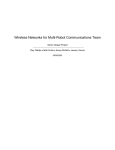
2. Plug the CMUcam1 AppMod into the AppMod connector located toward the front of the BoeBot
behind the white solder less bread board.
3. Be sure the camera lens is pointing forward across the top of the solder less bread board.
4. Double check that the CMUcam1 AppMod orientation is correct before proceeding.
5. Connect power to your BoeBot and observe that the CMUcam1 red power LED turns on. If the
CMUcam1 red power LED does not turn on disconnect the power immediately and double check the
orientation.
6. Remove the lens cap (shown at the bottom of this photo) when you are ready to use your CMUcam1
AppMod.
Note:
It’s a good idea to leave the lens cap in place when the CMUcam1 is not in use.
Try not to touch the surface of the CMUcam1 lens with your finger as it will leave an oily smudge that
could impair it’s proper function. To avoid scratching your lens only use a cleaning cloth designed for
either camera lenses or eye glasses to clean the CMUcam1 lens.
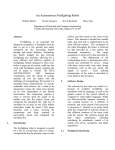
CMUcam1 tilt angle
For typical applications and the included eight function demo program you will want to adjust the
mounting bracket so your CMUcam1 has a downward tilt angle similar to the picture below. This allows
your BoeBot to see directly in front of it and a short distance forward and forward to the right and left. The
pivot point on the mounting bracket uses knurled head nylon screws that you can loosen and tighten by
hand. Be careful not to over tighten these screws as they are made of soft plastic and you can strip them.
You should use the camera tilt angle as a way of fine tuning the programs forward / backward and
right / left tracking performance.
Lens focus
The lens comes pre-focused for close-up to moderate range viewing, which works best with your BoeBot
for most applications. Once you are experienced using the CMUcam1 you may have an application that
requires a farther distant focus and you can gently turn the lens housing in or out to adjust.
Caution: The focus on the CMUcam1 is very sensitive. It will function as is for most any application using
the BoeBot. Be very careful when adjusting the focus to only change it in small increments. If it gets very
far out of focus it will have difficulty identifying and tracking objects close up and far away.
You should also be aware of the fact that technically speaking the CMUcam1 is mounted upside down on
its mounting bracket. This reverses the relationship of the X and Y data from the camera.
Battery Problems
If your CMUcam1 and BoeBot appear to work erratically chances are your batteries are discharged. The
CMUcam1 consumes a hefty 200 ma of power from your BoeBot voltage regulator and batteries. This will
make your batteries run down much sooner than before. Be sure and replace all four batteries at the
same time with quality alkaline batteries.
The AppMod essentially contains the Low Battery Indicator circuit from your Parallax Robotics Student
Workbook chapter 2, activity 1. This can help diagnose intermittent low battery problems. The integral
piezo speaker included on your CMUcam1 AppMod board acts as the Low Battery Indicator circuit.
The Eight Function Demo Code
Once you have your CMUcam1 AppMod vision system plugged into the BoeBot AppMod connector the
next step is to program the main demo code from the CDROM to your Basic Stamp2. The demo code has
eight functions each function demonstrating a capability of the CMUcam1. The AppMod interface board
has eight LED’s and two push buttons that function as a simple menu selection system. When you first
turn on the BoeBot the eight led’s will flash several times then the piezo speaker will beep indicating it is
ready. Each function starts with one audible beep and stops with two beeps. The LED’s flash during each
function in different patterns to let you know how that function is operating.
How to use the menu interface
Press the “Select” button repeatedly and you will see the LED’s light one after the other in sequence from
left to right. It helps to put a finger under the edge of the AppMod board as you depress the button. This
keeps the AppMod board from moving on it’s plug in connector mount. Press the “Go/Stop” button to start
a function. If a function is already activated press the “Go/Stop” button again to stop that function. You
may then press the “Select” button again to select another function.
The eight demo functions
Function 1 - “Calibrate Lighting” the first step after the BoeBot is turned on is to calibrate the CMUcam1
to the ambient lighting conditions. Press the Select button until the red LED “1” is lit, then press the
Go/Stop button. The LED’s will flash while the CMUcam1 is calibrating for the lighting conditions. This
takes about 20 seconds. Make sure the area is clear of objects in front of the BoeBot (out to about six
inches) and that you are in the typical lighting conditions you will be operating in. Avoid facing the camera
directly toward a light source. As you are using your BoeBot and if your lighting conditions change you
may wish to run this function again.
Function 2 - “Sample and Save Color” hold a colored object directly in front of the CMUcam1 lens (1 to 2
inches away) and then select function two and press the Go/Stop button. It takes about a second to lock
onto the color of the object and the LED’s will flash and the speaker will beep twice when done. The color
values are saved in the Basic Stamp 2 EEPROM. The sampled color will be saved even when the robot is
turned off.
Function 3 - “Track Color” the robot moves forward, backward, right and left to follow the color of the
object saved during function 2. The LED’s will light up to indicate which direction the robot will move. The
two center green LED’s illuminate for forward, the four red LED’s for backward and the one yellow LED
on each side for right and left turns. This is very useful for testing. The LED’s also flash briefly during
each look and move loop.
Function 4 - “Move and Avoid” the robot will move forward and avoid objects using the vision sensor
only. It works by sampling the color range of the floor in front of the robot. It then backs up and turns away
from anything it sees that is not the color of the floor. You must have the area in front of the robot object
free when you first start this function so it can sample the floor color correctly.
Function 5 - “Adaptive Tracking” the robot locks onto the first color it sees and tracks that color (it only
goes fwd, right and left, not bwd). If it loses the object for about five seconds it then locks onto the next
color it sees and tracks that until it loses that etc. You can hold any colored object in front of the robot and
it will beep fast twice to indicate it has locked onto the object it will track.
Function 6 – “Line Following” it is assumed a black line about ½” wide on a white line tracking course.
This is very simple basic line following. The CMUcam1 should be calibrated on the white line tracking
course background before you select this function.
Function 7 – “Finger Point and Move” the robot will backup, turn right and turn left in relation to finger
pointing. This is done with the CMUcam1 using the same downward facing angle as is used on all the
other functions. The hand is laid flat on the surface in front of the robot. One finger only is extended and
pointed toward the center of the robot facing head on toward the robot. As you get close to the front of the
robot it will backup. Your finger should be flat on the floor pointing straight at the center of the front of the
robot. To turn right and left the finger is laid flat on the floor and brought to approach the front of the robot
from each side, the robot will rotate toward the direction the finger is pointing.
Function 8 – “Show Color” the robot will light up either all of the red, green or yellow LED’s in response to
the color of the object placed in front of the robot. This is typically done with a 2” square (or larger) of red,
green or yellow construction paper. It also works well with 2” diameter colored rubber balls or plastic
blocks.
For best performance with all of the above functions the tilt of the camera should be pointing down
looking just in front of the robot. (there is a good picture of the proper angle in front of this manual)
You should try tilting the camera a little up or down to tune the tracking performance.
The camera tilt angle can make a big difference on tracking performance.
About the Demo Code
The demo code serves three purposes
1) Get you going quickly and easily using vision as the only sensor.
2) Demonstrate some of the things you can do with the CMUcam1.
3) You can learn how to accomplish things using the CMUcam1 and the Basic Stamp 2 by looking at
the documented demo source code provided on the CDROM.
Basic Stamp2sx and Basic Stamp2p
This CMUcam1 AppMod and demo code will also work with the more powerful 2sx and 2p versions of the Basic
Stamp. Separate versions of the demo code for each Stamp can be found on the CDROM. The code changes are
minor and related to the 2.5x faster execution speed.
You can do more with the CMUcam1 and the 2sx and 2p Stamps due to there faster speed and more memory. The
Basic Stamp2 is limited to 9600 baud serial interface speed to talk to the CMUcam1 but the 2sx and 2p can both talk
to the CMUcam1 at it’s maximum serial data rate of 115,200 baud. The CMUcam1 is switched to the 115,200 baud
rate by removing the two jumpers that can be found on the CMUcam1 board. The higher baud rate means your
BoeBot can respond much faster to the vision system.
About the CMUcam1
The functions provided by the CMUcam1 are meant to give the user a toolbox of color vision functions.
Actual applications may vary greatly and are left up to the imagination of the user. By being able to
change the viewable window, grab color / light statistics and track colors the user can interweave these
functions on the host processor (Basic Stamp) to create higher levels of functionality.
The CMUcam1 is a SX28 microcontroller (http://www.ubicom.com/products/processors/sx28ac.html)
interfaced with a OV6620 Omnivision CMOS camera (http://www.ovt.com/omnicmoss.htm) on a chip that
allows simple high level data to be extracted from the camera’s streaming video. The board
communicates using a TTL level serial port and has the following functionality:
• Track user defined color blobs at 17 Frames Per Second
• Find the centroid of the blob
• Gather mean color and variance data
• Arbitrary image windowing
• 80x143 Resolution
• 9600 baud serial communication
• Automatically detect a color and drive a servo to track an object
• Slave parallel image processing mode off a single camera bus – advanced function
• Ability to control 1 servo or have 1 digital I/O pin – advanced function
• Adjust the camera's image properties – advanced function
About the CMUcam1 camera module
When using the camera outside, due to the sun’s powerful IR (Infra-Red) emissions, even on relatively
cloudy days, it will probably be necessary to use either an IR cutoff filter or a neutral density 3 camera
filter to decrease the ambient light level. We have found a lens taken from a cheap drug store pair of
sunglasses when placed over the camera lens will allow the CMUcam1 to work in sun lit conditions.
Serial Communication format
The serial communication parameters are as follows:
• 9600 Baud
• 8 Data bits
• 1 Stop bit
• No Parity
• No Flow Control (Not Xon/Xoff or Hardware)
All commands are sent using visible ASCII characters (123 is 3 bytes "123" ). Upon a successful
transmission of a command, the ACK string should be returned. If there was a problem in the syntax of
the transmission, or if a detectable transfer error occurred, a NCK string is returned. After either an ACK
or a NCK, a \r is returned. When a prompt ('\r' followed by a ':' ) is returned, it means that the camera is
waiting for another command in the idle state. White spaces do matter and are used to separate
argument parameters. The \r (ASCII 13 carriage return) is used to end each line and activate each
command. If visible character transmission exerts too much overhead, it is possible to use varying
degrees of raw data transfer. (See Raw Mode)
CMUcam1 color balance
Better Tracking with Auto-gain and White-balance
Auto-gain is an internal control that adjusts the brightness level of the image to best suit the environment.
It attempts to normalize the lights and darks in the image so that they approximate the overall brightness
of a hand adjusted image. This process iterates over many frames as the camera automatically adjusts its
brightness levels. If for example a light is turned on and the environment gets brighter, the camera will try
and adjust the brightness to dim the overall image.
White-balance on the other hand attempts to correct the camera’s color gains based on the ambient light
conditions and the environment. The ambient light in your image may not be pure white. In this case, the
camera will see colors differently. The camera begins with an initial guess of how much gain to give each
color channel. If active, white-balance will adjust these gains on a frame-by-frame basis so that the
average color in the image approaches a gray color. Empirically, this “gray world” method has been found
to work relatively well. The problem with gray world white-balance is that if a solid color fills the camera’s
view, the white-balance will slowly set the gains so that the color appears to be gray and not its true color.
Then when the solid color is removed, the image will have undesirable color gains until it re-establishes
its gray average.
Utility programs Also included on the CD-ROM are the following utility programs.
Program 1 – Test CMUcam1 to BoeBot communication
This program sets up a 9600-baud serial connection between the Stamp and the CMUcam1. It then tells
the CMUcam1 to blink its green LED.
Program 2 – Display CMUcam1 tracking data on debug screen
The first data packet displayed by the Debug screen is the “S” Statistics packet which tells you the color
of the object it is tracking. The Stamp then loops displaying on your PC debug screen The “M” Track
Color (TC) packet once per second. You will want to move your object being tracked around and watch
the PC debug screen. This will let you evaluate the ability of your camera to track an object. Try different
color objects and different sizes to see the effects on the tracking data.
This is an important program that you will re-use many times as you as you find more and more
interesting things to do with your CMUcam1 and BoeBot. This program allows you to see and understand
exactly what your BoeBot can see with its CMUcam1 vision system.
CMUcam1 Calibration procedure - Important
To successfully identify and track colored objects using the CMUcam1 you must calibrate the
CMUcam1 to the lighting environment in which it will be operating. The main eight function demo
program does this with function 1
To better identify and track colors, this utility program begins by adjusting the auto-gain and whitebalance to the environment in which you are operating your BoeBot. Once set they are turned off during
operation.
To use this program follow these steps 1. Place the robot on the floor of the area in which it will be operating with no objects in front of it.
2. Hold the BoeBot reset button down and release.
3. After about a one second delay the green LED on the CMUcam1 (next to the red power LED) will
illuminate for 5 seconds while the CMUcam1 is calibrating to your lighting conditions.
4. When the green LED turns off you have 5 seconds to place your object to be tracked in front of the
camera.
5. Hold the object to be tracked a few inches away and directly in front of the CMUcam1 until the green
LED illuminates again. Please note - When locking onto the color to be tracked the CMUcam1
samples a small area in the center of the image. If you wish to track small objects smaller than 3”
diameter it may take trial and error testing to determine exactly where to hold the object so the
CMUcam1 will properly lock onto the objects color.
6. The CMUcam1 is now ready to track objects of that color.
Basic Command Set
\r (the “enter” or “return” key)
This command is used to set the camera board into an idle state. Like all other
commands, you should receive the acknowledgment string "ACK” or the not
acknowledge string "NCK" on failure. After acknowledging the idle command the
camera board waits for further commands, which is shown by the ':' prompt. While in
this idle state a /r by itself will return an "ACK" followed by \r and : character prompt.
Example of how to check if the camera is alive while in the idle state
:
ACK
:
GM\r
This command will Get the Mean color value in the current image. As with the TC
command this function only operates on a selected region of the image. The mean
values will be between 16 and 240. It will also return a measure of the average absolute
deviation of color found in that region. The mean together with the deviation can be a
useful tool for automated tracking or detecting change in a scene. In YCrCb mode RGB
maps to CrYCb.
Type S data packet format
S Rmean Gmean Bmean Rdeviation Gdeviation Bdeviation\r
Example of how to grab the mean color of the entire window
:SW 1 1 40 143
ACK
:GM
ACK
S 89 90 67 5 6 3
S 89 91 67 5 6 2
L1 value\r
This command is used to control the green LED tracking Light. It accepts 0, 1 and 2 (default) as inputs. 0
disables the tracking light while a value of 1 turns on the tracking light. A value of 2 puts the light
into its default auto mode. In auto mode and while tracking, the light turns on when it detects the
presence of an object that falls within the current tracking threshold. This command is useful as a
debugging tool.
Example of how to toggle the Tracking Light on and then off
:L1 2
ACK
:L1 0
ACK
MM mode\r
This command controls the Middle Mass mode which adds the centroid coordinates to the normal
tracking data. A mode value of 0 disengages middle mass, a value of 1(default) engages middle
mass and a value of 2 engages the mode and turns on the servo PWM signal that tries to center the
camera on the center of color mass (see the Demo Mode Jumper description). This mode is good
if you want a single point representation of where the object is or if there is too much small
background noise to get a good bounding box. To switch the direction of the servo it is necessary
to set the 2nd bit (counting from 0 i.e. bit-wise OR in the value 4) of the mode value. If the 3rd bit
is set (bit-wise OR in the value 8), then tracking a color will return a type N packets that is identical
to a type M packet, only it contains the current servo position as its first return value (see Output
Data Packet Description section).
Example of how to disable Middle Mass mode
:MM 0
ACK
:TC
ACK
C 38 82 53 128 35 98
C 38 82 53 128 35 98
C 38 82 53 128 35 98
NF active\r
This command controls the Noise Filter setting. It accepts a Boolean value 1 (default) or 0. A
value of 1 engages the mode while a value of 0 deactivates it. When the mode is active, the
camera is more conservative about how it selects tracked pixels. It requires 2 sequential pixels for
a pixel to be tracked.
Example of how to turn off noise filtering
:NF 0
ACK
:
PM mode\r
This command puts the board into Poll Mode. Setting the mode parameter to 1 engages poll mode
while 0 (default) turns it off. When poll mode is engaged only one packet is returned when an
image processing function is called. This could be useful if you would like to rapidly change
parameters or if you have a slow processor that can't keep up with a given frame rate.
Example of how to get one packet at a time
:PM 1
ACK
:TC 50 20 90 130 70 255
ACK
C 38 82 53 128 35 98
:
RS \r
This command ReSets the vision board. Note, on reset the first character is a /r.
Example of how to reset the camera
:rs
ACK
CMUcam v1.12
:
SW [x y x2 y2] \r
This command Sets the Window size of the camera. It accepts the x and y Cartesian coordinates
of the upper left corner followed by the lower right of the window you wish to set. The origin is
located at the upper left of the field of view. SW can be called before an image processing
command to constrain the field of view. Without arguments it returns to the default full window
size of 1,1,80,143.
Example of setting the camera to select a mid portion of the view
:SW 35 65 45 75
ACK
:
TC [Rmin Rmax Gmin Gmax Bmin Bmax]\r
This command begins to Track a Color . It takes in the minimum and maximum RGB (CrYCb)
values and outputs a type M or C data packet (set by the MM command). The smaller type C
packet encodes a bounded box that contains pixels of the currently defined color, the number of
found pixels (scaled: actual value is (pixels+4)/8 ) that fall in the given color bounds and a
confidence ratio. The default type M packet also includes the center of mass of the object. The
resolution of the processed image is 80x143. The X values will range from 1 to 80 and the y
values will range from 1 to 143. A packet of all zeros indicates that no color in that range was
detected. The confidence value is a ratio of the pixels counted within the given range and the area
of the color bounding box. It returns a value which ranges from 0 to 255. Under normal
operations any value greater then 50 should be considered a very confident lock on a single
object. A value of 8 or lower should be considered quite poor. With no arguments, the last color
tracking parameters will be repeated.
Type M packet
M mx my x1 y1 x2 y2 pixels confidence\r
Type C packet
C x1 y1 x2 y2 pixels confidence\r
Example of how to Track a Color with the default mode parameters
:TC 130 255 0 0 30 30
ACK
M 50 80 38 82 53 128 35 98
M 52 81 38 82 53 128 35 98
M 51 80 38 82 53 128 35 98
TW \r
This command will Track the color found in the central region of the current Window. After the
color in the current window is grabbed, the track color function is called with those parameters
and on the full screen. This can be useful for locking onto and tracking an object held in front of
the camera. Since it actually calls track color, it returns the same type of C or M color packet.
Note, your set window will only be used for grabbing the color to track and then the window will
return to 80x143.
Example of how to use Track Window:
:TW
ACK
S 240 50 40 12 7 8
C 2 40 12 60 10 70
C 3 41 12 61 11 70
C 2 40 12 60 13 70
C 3 42 12 62 9 70
C 4 45 12 60 8 70
Output Data Packet Descriptions - Basic
All output data packets are in ASCII viewable format.
ACK
This is the standard acknowledge string that indicates that the command was received and
fits a known format.
NCK
This is the failure string that is sent when an error occurred. The only time this should be
sent when an error has not occurred is during binary data packets.
Type C packet
This is the return packet from a color tracking command.
x1 - The left most corner's x value
y1 - The left most corner's y value
x2 - The right most corner's x value
y2 -The right most corner's y value
pixels –Number of Pixels in the tracked region, scaled and capped at 255: (pixels+4)/8
confidence -The (# of pixels / area)*256 of the bounded rectangle and capped at 255
C x1 y1 x2 y2 pixels confidence\r
Type M packet
This is the return packet from a color tracking command with Middle Mass mode on.
mx - The middle of mass x value
my - The middle of mass y value
x1 - The left most corner's x value
y1 - The left most corner's y value
x2 - The right most corner's x value
y2 -The right most corner's y value
pixels –Number of Pixels in the tracked region, scaled and capped at 255: (pixels+4)/8
confidence -The (# of pixels / area)*256 of the bounded rectangle and capped at 255
M mx my x1 y1 x2 y2 pixels confidence\r
Type S data packet format
This is a statistic packet that gives information about the camera's view
Rmean - the mean Red or Cr (approximates r-g) value in the current window
Gmean - the mean Green or Y (approximates intensity) value found in the current window
Bmean - the mean Blue or Cb (approximates b-g) found in the current window
Rdeviation - the *deviation of red or Cr found in the current window
Gdeviation- the *deviation of green or Y found in the current window
Bdeviation- the *deviation of blue or Cb found in the current window
S Rmean Gmean Bmean Rdeviation Gdeviation Bdeviation\r
*deviation: The mean of the absolute difference between the pixels and the region mean.
Information for advanced users
Servo Port
This is the output for the servo. The positive signal does not go through a regulator from the board’s
power input. Do not use a servo with the board if the board is being run off of more than 6 volts.
Parallel Processing in Slave Mode
The CMUcam1 supports a mode of operation that allows multiple boards to process data from the same
camera. If a PC104 style pass-through header is used instead of the standard double row female header,
it is possible to rack multiple boards along the same camera bus. Upon startup, if jumper 1 is set, the
camera becomes a slave. Slave mode stops the camera board from being able to configure or interfere
with the CMOS camera’s settings. Instead it just processes the format setup by the master vision board.
When linking the buses together you must only have one master; all other boards should be setup to be
in slave mode. In this current version of the system there is no message passing between boards other
than the image data from the camera bus. This means you have to communicate to each slave board via
a separate serial link. This communication to the board should be identical to using a single CMUcam1.
For example, you could have the master board tracking some color while the slave board could be told to
get mean color data. Each board runs independently of one another and only the master can control
camera registers.
Advanced Command Set
CR [ reg1 value1 [reg2 value2 ... reg16 value16] ]\r
This command sets the Camera's internal Register values directly. The register locations and
possible settings can be found in the Omnivision documentation. All the data sent to this
command should be in decimal visible character form unless the camera has previously been set
into raw mode. It is possible to send up to 16 register-value combinations. Previous register
settings are not reset between CR calls; however, you may overwrite previous settings. Calling
this command with no arguments resets the camera and restores the camera registers to their
default state.
Useful Settings:
Register
Values
3 Saturation
5 Contrast
6 Brightness
0-255 (default = 128)
0-255 (default = 72)
0-255 (default = 128)
17 Clock Speed
2
3
4
5
6
7
8
10
12
17 fps (default)
13 fps
11 fps
9 fps
8 fps
7 fps
6 fps
5 fps
4 fps
18 Color Mode
0 YCrCb*, AGC off, Auto White-balance Off
4 YCrCb*, AGC off, Auto White-balance On
32 YCrCb*, AGC on, Auto White-balance Off
36 YCrCb*, AGC on, Auto White-balance On
8 RGB, AGC off, Auto White-balance Off
12 RGB, AGC off, Auto White-balance On
40 RGB, AGC on, Auto White-balance Off (default)
44 RGB, AGC on, Auto White-balance On
> Turns off or on both the Auto White-balance and Auto-gain Controls
19 Auto Adjust
32 Auto Adjust Off
33 Auto Adjust On (default)
> Use the Band Filter with Fluorescent lighting
45 Band Filter
3 Band Filter Off (default)
7 Band Filter On
Example of decreasing the internal camera clock speed (default speed is 2)
:CR 17 5
ACK
:
*The red channel becomes Cr which approximates r-g, The green channel becomes Y which
approximates
intensity, the blue channel becomes Cb which approximates b-g
RGB -> CrYCb
Y=0.59G + 0.31R + 0.11B
Cr=R-Y
Cb=B-Y
DF\r
This command will Dump a Frame out the serial port to a computer. This is the only
command that will by default only return a non-visible ASCII character packet. It dumps
a type F packet that consists of the raw video data column by column with a frame
synchronize byte and a column synchronize byte. (This data can be read and displayed
by the CMUcam1 GUI Java application. ) Since the data rate required to send the raw video
greatly exceeds the maximum serial port speed, only one column per frame is sent at a
time. This allows you to see a slowly updating view of what the camera sees. To get the
correct aspect ratio, double each column of pixels. The camera is able to dump a full
resolution frame at full speed (17 columns per second) only at 115,200 baud. At lower
baud rates, or 115,200 baud with added delays the frame rate must be decreased in order
to see a full resolution image. With auto-gain on and at lower frame rates, the image at
first may appear much brighter than usual. This is because the camera is getting frames
slower than usual and takes longer to adapt. Try manually setting the brightness and
contrast.
Type F data packet format
1 - new frame
2 - new col
3 - end of frame
RGB (CrYCb) ranges from 16 - 240
1 2 r g b r g b ... r g b r g b 2 r g b r g b r ... r g b r g b ...
Example of a Frame Dump from a terminal program
(WARNING: This may temporarily interfere with a terminal program by sending nonvisible
characters)
:DF
ACK
maKP(U A$IU AL<>U A$L*YL%*L L (G AUsonthAYA(KMAy098a34ymawvk....
DM value\r
This command sets the Delay before packets that are transmitted over the serial port. The value
should be set between 0 and 255. A value of 0 (default) has no delay and 255 sets the maximum
delay. Each delay unit correlates to approximately the transfer time of one bit at the current baud
rate.
GV\r
This command Gets the current Version of the firmware from the camera. It returns an
ACK followed by the firmware version string.
Example of how to ask for the firmware version
:GV
ACK
CMUcam v1.12
HM active\r
This command puts the camera into Half-horizontal resolution Mode for the DF command and the
LM command when dumping a bitmap image. An active value of 1 causes only every odd column
to be processed. The default value of 0 disables the mode.
I1 \r
This command uses the servo port as a digital Input. Calling I1 returns either a 1 or 0 depending
on the current voltage level of the servo line. The line is pulled high; because of this it is only
required to pull it low or let it float to change it’s state. The servo line can also be used as a digital
output. ( See S1 command)
Example of how to read the digital value of the servo line
:I1
ACK
1
LM active\r
This command turns on Line Mode which uses the time between each frame to transmit more
detailed data about the image. It adds prefix data onto either C, M or S packets. This mode is
intended for users who wish to do more complex image processing on less reduced data. Since the
frame rate is not compromised, the actual processing of the data put out by the vision system must
be done at a higher rate. This may not be suitable for many slower microcontrollers.
Line mode’s effect on TC and TW:
When line mode is active and TC or TW is called, line mode will send a binary bitmap of
the image as it is being processed. It will start this bitmap with an 0xAA flag value (hex value AA
not in human readable form). The value 0xAA will not occur in the data stream. This is followed
by bytes each of which contains the binary value of 8 pixels being streamed from the top-left to
the bottom-right of the image. The vertical resolution is constrained by the transfer time of the
horizontal data so lines may be skipped when outputting data. In full resolution mode, the
resulting binary image is 80x48. The binary bitmap is terminated by two 0xAA’s. This is then
followed by the normally expected standard C or M data packet (processed at that lower
resolution).
Example of TC with line mode on
:LM 1
:TC
(raw data: AA XX XX XX …. XX XX XX AA AA) C 45 72 65 106 18 51
(raw data: AA XX XX XX …. XX XX XX AA AA) C 46 72 65 106 18 52
Line mode’s effect on GM:
When line mode is active and GM is called, line mode will send a raw (not human
readable) mean value of every line being processed. These packets are started with an 0xFE and
terminate with an 0xFD. Each byte of data between these values represents the corresponding
line’s mean color value. Similarly to the bitmap mode the vertical resolution is halved, because of
the serial transfer time. At 17 fps 115,200 baud every other line is skipped. At any slower frame
rate (still 115,200 baud) no lines will be skipped.
Example of GM with line mode on
:LM 1
:GM
(raw data: FE XX XX XX … XX XX XX FD) M 45 56 34 10 15 8
(raw data: FE XX XX XX … XX XX XX FD) M 45 56 34 10 15 8
RM bit_flags\r
This command is used to engage the Raw serial transfer Mode. It reads the bit values of the first 3
(lsb) bits to configure settings. All bits cleared sets the default visible ASCII mode. If bit 0 is set,
then all output from the camera is in raw byte packets. The format of the data packets will be
changed so as not to include spaces or be formatted as readable ASCII text. Instead you will
receive a 255 valued byte at the beginning of each packet, followed by the packet and the packet
identifying character (i.e. C for a color packet). There is no \r sent after each packet, so you must
use the 255 to synchronize the incoming data. Any 255 valued bytes that may be sent as part of
the packet are set to 254 to avoid confusion. If bit 1 is set, the “ACK\r” and “NCK\r”
confirmations are not sent. If bit 3 is set, input will be read as raw byte values, too. In this mode,
after the two command byte values are sent, send 1 byte telling how many arguments are to
follow. (i.e. DF followed by the raw byte value 0 for no arguments) No \r character is required.
If bit 0 is enabled, then output to the camera is in raw bytes
If bit 1 is enabled, then the “ACK\r” and “NCK\r” confirmations are suppressed
If bit 2 is enabled, then input to the camera is in raw bytes
Example of the new packet for Track Color with Raw Mode output only
(WARNING: This may temporarily interfere with a terminal program by sending non
visible characters)
:RM 1
ACK
:TC 50 20 90 130 70 255
ACK
C>%k(ai Ck$&,.L
S1 position \r
This command lets you Set the position of servo 1. 0 turns the servo off and holds the line low. 1127 will set the servo to that position while it is tracking or getting mean data. Any value 128 and
higher sets the line high. In order for the servo to work, the camera must be in either a tracking
loop or mean data gather loop. Values 0 and 128 can be useful if you wish to use the servo port as
a digital output. The port can also be used as a digital input (see I1 command). The “MM”
command can enable or disable the automatic servo tracking.
SM value \r
This command is used to enable the Switching Mode of color tracking. When given a 0 it is in it's
default mode where tracking will return its normal C or M color packet. If the value is set to 1, the
tracking commands will alternate each frame between color packets and S statistic packets. Each
statistic packet is only being sampled from an area one quarter the size of the bounded area
returned from the tracking command. If no object was bounded, then no S statistic packets are
returned. This can be useful for adaptive tracking or any type of tracking where you would like to
get feedback from the currently bound target. After the first tracking packet is returned, the
window gets set back to full size for all future packets. Note, you will get only half the number of
actual color packets per time interval.
Example of how to Track Color with SM
:SM 1
ACK
:TC 200 255 0 30 0 30
ACK
C 2 40 12 60 10 70
S 225 20 16 2 3 1
C 5 60 20 30 12 100
S 225 19 17 1 2 1
C000000
C000000
C000000
C 5 60 20 30 12 100
S 225 19 17 1 2 1
Output Data Packet Descriptions - Advanced
All output data packets are in ASCII viewable format except for the F frame and prefix packets.
ACK
This is the standard acknowledge string that indicates that the command was received and
fits a known format.
NCK
This is the failure string that is sent when an error occurred. The only time this should be
sent when an error has not occurred is during binary data packets.
Type N packet
This is identical to a type M packet with an added value for the servo position.
spos – The current position of the servo
N spos mx my x1 y1 x2 y2 pixels confidence\r
Binary bitmap Line Mode prefix packet
This packet is in raw byte form only. It starts off with the hex value 0xAA and then streams bytes,
with each byte containing a mask for 8 pixels, from the top-left to the bottom-right of the image.
(Each binary bit in the byte represents a pixel) The bitmap is then terminated with two 0xAAs.
0xAA is never transmitted as part of the data, so it should be used to signify termination of the
binary bitmap. After the binary bitmap is complete, a normal tracking packet should follow.
(raw data: AA XX XX XX …. XX XX XX AA AA) C 45 72 65 106 18 51
(raw data: AA XX XX XX …. XX XX XX AA AA) C 46 72 65 106 18 52
Get mean Line Mode prefix packet
This packet prefix outputs the mean color of each row being processed. These packets are started
with an 0xFE and terminate with an 0xFD. Each byte of data between these values represents the
corresponding line’s mean color value. Due to the serial transfer time, the vertical resolution is
halved. After all rows have been completed, a normal tracking packet should follow.
(raw data: FE XX XX XX … XX XX XX FD) M 45 56 34 10 15 8
(raw data: FE XX XX XX … XX XX XX FD) M 45 56 34 10 15 8
Type F data packet format
1 - new frame 2 - new col 3 - end of frame
RGB (CrYCb) ranges from 16 - 240
RGB (CrYCb) represents a two pixels color values. Each pixel shares the red and blue.
176 cols of R G B (Cr Y Cb) packets (forms 352 pixels)
144 rows
To display the correct aspect ratio, double each column so that your final image is 352x144
It does not begin with an “F” and only sends raw data!
1 2 r g b r g b ... r g b r g b 2 r g b r g b ... r g b r g b ...
Technical Support
Parallax, Inc.
www.parallax.com
[email protected]
www.forums.parallax.com.
Toll free
1-888-997-8267
Mon – Fri, 7a.m. to 5 p.m. PST
Seattle Robotics
www.seattlerobotics.com
[email protected]
(253) 630-9836
Fax: (253) 630-9914
Carnegie Mellon University
http://www.cs.cmu.edu/~cmucam
[email protected]
Quick Guide
Demo program
Press “Select” button to move between each Function LED.
Press “Go/Stop” button to begin or end a Function.
Function 1 - Calibrate Lighting
Function 2 – Sample and Save Color
Function 3 – Track Color
Function 4 – Move and Avoid
Function 5 – Adaptive Tracking
Function 6 – Line Following
Function 7 – Finger Point and Move
Function 8 – Show Color
Basic CMUcam1 commands
GM - Get Mean
L1 [0 or 1 or 2] – LED control (green)
RS - Reset
SW [x, y, x2, y2] – Set Window
TC [Rmin, Rmax, Gmin, Gmax, Bmin, Bmax] – Track Color
TW [Rmin, Rmax, Gmin, Gmax, Bmin, Bmax] - Track Window
Basic CMUcam1 data packet
Type C data packet format
This is the return packet from a color tracking command.
x1 - The left most corner's x value
y1 - The left most corner's y value
x2 - The right most corner's x value
y2 -The right most corner's y value
pixels –Number of Pixels in the tracked region, scaled and capped at 255: (pixels+4)/8
confidence -The (# of pixels / area)*256 of the bounded rectangle and capped at 255
C x1 y1 x2 y2 pixels confidence\r
Type S data packet format
This is a statistic packet that gives information about the camera's view
Rmean - the mean Red or Cr (approximates r-g) value in the current window
Gmean - the mean Green or Y (approximates intensity) value found in the current window
Bmean - the mean Blue or Cb (approximates b-g) found in the current window
Rdeviation - the *deviation of red or Cr found in the current window
Gdeviation- the *deviation of green or Y found in the current window
Bdeviation- the *deviation of blue or Cb found in the current window
S Rmean Gmean Bmean Rdeviation Gdeviation Bdeviation\r
*deviation: The mean of the absolute difference between the pixels and the region mean.
Mouser Electronics
Authorized Distributor
Click to View Pricing, Inventory, Delivery & Lifecycle Information:
Parallax:
30051