1
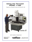
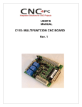
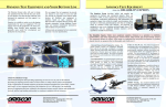
Emergency Stop Switch
p/n P-SW1 and P-SW2
INSTALLATION / USER MANUAL
FOR
EMERGENCY STOP SWITCH
MODEL P-SW1
MODEL P-SW2
Note: P-SW1 Cable color may be different (either white, black, gray, or yellow)
This Document is available online at: http://www.pasyl.com/docs/sw1-sw2.pdf
MODEL P-SW1 IS COMPATIBLE WITH:
ALL MECHATRONICS™ STEPPER MOTOR DRIVERS.
ALL ZENBOT™ CNC CONTROL BOXES.
OTHER STEPPER MOTOR DRIVERS USING DISCRETE GROUNDS TO STOP AXIS MOVEMENTS.
MODEL P-SW2 IS COMPATIBLE WITH:
ALL MECHATRONICS™ STEPPER MOTOR DRIVERS (May need DC Power Adapters.)
ALL ZENBOT™ CNC CONTROL BOXES USING 5.5mm x 2.5mm CONNECTORS (All are as of Oct 2011).
STEPPER MOTOR DRIVERS USING LAPTOP DC POWER SUPPLIES WITH 5.5mm x 2.5mm
CONNECTORS. UNITS WITH OTHER CONNECTORS WILL REQUIRE DC ADAPTERS.
First issue dated: Nov 05, 2011
Rev 01: Nov 11, 2011
Emergency Stop Switch
p/n P-SW1 and P-SW2
This page intentionally left blank
First issue dated: Nov 05, 2011
Rev 01: Nov 11, 2011
Emergency Stop Switch
p/n P-SW1 and P-SW2
Table of Contents
Page
Models P-SW1 and P-SW2 777777777777................... 2
Unpacking and Assembling the Unit 7777777777777.
4
P-SW1 Installation - Zenbot™CNC Control Box 777777777. 6
P-SW1 Installation – MECHATRONICS™ Boards7777777...
11
Testing 7777777777777777777777777..
15
Start/Stop Operation 7777777777777777777...
15
First issue dated: Oct 23, 2011
Rev 01: Nov 11, 2011
Page 1 of 16
Emergency Stop Switch
p/n P-SW1 and P-SW2
Models P-SW1 and P-SW2
CAUTION: Opening the Zenbot™ CNC Control Box May
Void the Warranty! Contact Zenbot™ and/or
Mechatronics™ if in doubt.
Note: Model P-SW2 Does not require installation, jump to page 3
Model P-SW1 (3-Axis Movement Stop - Ground Discretes)
Figure 1: P-SW1 Emergency Stop Switch – Minimum Wiring Required (o soldering)
Note: P-SW1 Cable color may be different (either white, black, gray, or yellow)
This Stop Switch Assembly requires drilling a hole in the stepper motor driver
enclosure (i.e.: Zenbot™ CNC Control Box), and the connection of four wires to the
terminals of the stepper-motor driver circuit-board. A strain relief is included to
secure the cable through an enclosure 31/64 inch diameter hole.
Zenbot™ uses Mechatronics™ boards. Installation should take between 5 and 15
minutes. No soldering is required. There are only 4 wires to connect to a terminal
strip on the circuit board. Wires are secured to the terminal strip with screws. You
will require a miniature common screw driver.
First issue dated: Oct 23, 2011
Rev 01: Nov 11, 2011
Page 2 of 16
Emergency Stop Switch
p/n P-SW1 and P-SW2
Model P-SW2 (Power Switch – Plug N’ Play)
Figure 2: P-SW2 Emergency Stop Switch – o Wiring Required (Plug n’ Play)
Power input through a 5.5mm x 2.5mm Metal Housing DC Power Jack and
output through a 5.5mm x 2.5mm DC Coaxial Plug with 18 AWG Power Cord.
This Stop Switch Assembly does not require installation for the Zenbot™ CNC
machines. Simply connect the Zenbot™ power supply to the unit, and the unit
cable to the Zenbot™ CNC Control Box. This unit cuts off power to the stepper
motor driver when the switch in pushed-in. To reset, you must turn the mushromm
button clockwise until the button pops up. Other DC powered stepper motor drivers
may need DC adapters if not using 5.5mm x 2.5mm jacks and plugs.
First issue dated: Oct 23, 2011
Rev 01: Nov 11, 2011
Page 3 of 16
Emergency Stop Switch
p/n P-SW1 and P-SW2
Unpacking and Assembling
Unpacking and Assembling the Unit
The Stop Switch Assembly may be shipped partially disassembled to minimize
shipping costs, assemble it as follows:
(Refer to Figures 1 below.)
1. Remove the four screws (6) attaching the lower cover (5) to the enclosure
(2).
2. Remove the mushroom button (4), black holding nut (3), and four screws (6)
from inside the enclosure (2).
3. Insert the switch (1) through the upper hole of the enclosure (2).
4. Insert the switch black holding nut (3) over the threads of the switch (1).
5. Hand tighten the black holding nut (3). Do not over tight.
6. Install the mushroom button (4) on the switch (1) by rotating clock-wise.
7. Attach the lower cover (5) with four included screws (6).
First issue dated: Oct 23, 2011
Rev 01: Nov 11, 2011
Page 4 of 16
Emergency Stop Switch
p/n P-SW1 and P-SW2
Figure 3: Assembly
First issue dated: Oct 23, 2011
Rev 01: Nov 11, 2011
Page 5 of 16
Emergency Stop Switch
p/n P-SW1 and P-SW2
Table 1: Tools Required
Note: Equivalent substitutes may be used
Tool Name
Possible Source
Use
Small Phillips Screw Driver
Commercial Off-the-Shelf
To attach bottom cover
Miniature common screw
driver
Commercial Off-the-Shelf
To secure wires to
circuit board terminals
31/64 inch Drill bit
Commercial Off-the-Shelf
Make hole in stepper
motor driver enclosure
for cable stress relief
and cable
P-SW1 Installation - Zenbot™ CC Control Box
1. Remove the four screws that attach the bottom cover of the Zenbot™ CNC
Control Box to the top cover.
2. Remove the top cover.
3. Inspect the back-left side of the the Zenbot™ CNC Control Box to make
sure drilling a hole will not cause any damage (make sure there are no
obstructions.)
4. Using a black marker, draw a dot on the back plate of the Zenbot™ CNC
Control Box where you want to drill the 31/64 diameter hole.
5. Re-Install the cover (it is easier to drill the hole with the top cover installed.)
6. Drill the 31/64 inch diameter hole. See Fig 4 and Fig 5 Below.
First issue dated: Oct 23, 2011
Rev 01: Nov 11, 2011
Page 6 of 16
Emergency Stop Switch
p/n P-SW1 and P-SW2
Fig 4: Removing the four screws
7. Drill a 31/64 inch diameter hole, centered approximately 3/8 inch from upper
edge, and approximately ½ inch from left edge on the back plate. The hole
must be exactly 31/64 inch diameter for the Strain Relief to fit correctly into
the hole and hold the cable tightly.
First issue dated: Oct 23, 2011
Rev 01: Nov 11, 2011
Page 7 of 16
Emergency Stop Switch
p/n P-SW1 and P-SW2
Fig 5: Hole drilling location
Note: Cable color may be different (either white, black, gray, or yellow)
8. Connect the wires of the unit cable to the terminal strips as follows:
a. Unscrew the four terminal screws X, Y, X, and COM.
b. Connect the black wire to the COM terminal (refer to Figures below)
and tighten the terminal screw.
c. Connect the other wires to the LIMIT SWITCHES X, Y, and Z
terminals and tighten the terminal screws. If installing the switch on a
4-axis CNC driver, install a jumper wire between one of the X, Y, or Z
axis terminal to the “A” Terminal.
First issue dated: Oct 23, 2011
Rev 01: Nov 11, 2011
Page 8 of 16
Emergency Stop Switch
p/n P-SW1 and P-SW2
Fig 6: X, Y, Z, COM Terminals
9. Install the strain relief over the cable.
Fig 7: Strain Relief
Note: Cable color may be different (either white, black, gray, or yellow)
First issue dated: Oct 23, 2011
Rev 01: Nov 11, 2011
Page 9 of 16
Emergency Stop Switch
p/n P-SW1 and P-SW2
10. Insert the strain relief inside the back plate hole. You may have the twist and
rotate for the strain relief to go in.
11. Install the four screws that attach the bottom cover of the Zenbot™ CNC
Control Box to the top cover.
Fig 8: Strain Relief (Will need twisting to go in)
Note: Cable color may be different (either white, black, gray, or yellow)
First issue dated: Oct 23, 2011
Rev 01: Nov 11, 2011
Page 10 of 16
Emergency Stop Switch
p/n P-SW1 and P-SW2
Fig 9: Fully insert strain relief into 31/64 in. dia. Hole
Note: Cable color may be different (either white, black, gray, or yellow)
P-SW1 Installation – MECHATRONICS™
Boards
1. Locate a good location to pass the cable through the enclosure (if any).
2. Drill a 31/64 inch diameter hole in the spot selected. The hole must be
exactly 31/64 inch diameter for the Strain Relief to fit correctly into the hole
and hold the cable tightly.
First issue dated: Oct 23, 2011
Rev 01: Nov 11, 2011
Page 11 of 16
Emergency Stop Switch
p/n P-SW1 and P-SW2
Fig 10: Hole drilling location
Note: Cable color may be different (either white, black, gray, or yellow)
3. Insert the cable through the hole.
4. Connect the wires of the unit cable to the terminal strips as follows:
a. Unscrew the four terminal screws X, Y, X, and COM.
b. Connect the black wire to the COM terminal (refer to Figures below)
and tighten the terminal screw.
c. Connect the other wires to the LIMIT SWITCHES X, Y, and Z
terminals and tighten the terminal screws. If installing the switch on a
4-axis CNC driver, install a jumper wire between one of the X, Y, or Z
axis terminal to the “A” Terminal.
First issue dated: Oct 23, 2011
Rev 01: Nov 11, 2011
Page 12 of 16
Emergency Stop Switch
p/n P-SW1 and P-SW2
Fig 11: X, Y, Z, COM Terminals
Note: Cable color may be different (either white, black, gray, or yellow)
5. Install the strain relief over the cable.
Fig 12: Strain Relief
6. Insert the strain relief inside the chosen hole. You may have the twist and
rotate for the strain relief to go in.
First issue dated: Oct 23, 2011
Rev 01: Nov 11, 2011
Page 13 of 16
Emergency Stop Switch
p/n P-SW1 and P-SW2
Fig 13: Strain Relief (Will need twisting to go in)
Note: Cable color may be different (either white, black, gray, or yellow)
Fig 14: Fully insert strain relief Inside Drilled Hole
12. Attach any cover if removed previously removed.
First issue dated: Oct 23, 2011
Rev 01: Nov 11, 2011
Page 14 of 16
Emergency Stop Switch
p/n P-SW1 and P-SW2
Testing
WARNING: YOU MUST DO THESE STEPS TO ENSURE THAT ALL AXIS
MOVEMENTS WILL STOP WHEN THE EMERGENCY SWITCH BUTTON IS
PUSHED! THESE STEPS ASSUME YOU HAVE MACH3 SOFTWARE RUNNING.
IF USING DIFFERENT SOFTWARE, MAKE SURE THAT EVERY AXIS CAN BE
STOPPED WITH THE SWITCH.
1. Turn on the driver unit and start the CNC Software.
2. Make sure that you can move the CNC machines with the computer
keyboard left arrow, right arrow, up arrow, down arrow, page up and page
down keys.
3. Push in the Emergency Stop Switch.
4. Make sure that the computer keyboard left arrow, right arrow, up arrow,
down arrow, page up and page down keys do not cause the CNC machine
to move.
CONGRATULATION! YOU HAVE COMPLETED THE INSTALLATION!
Start/Stop Operation
CAUTION: YOU MUST TEST THE UNIT BEFORE STARTING MACHINE
OPERATION!
1. Push down the mushroom button to stop/de-energize the unit.
2. Turn the mushroom button clockwise to turn on/energize the unit.
NOTE: The CAM software does not stop when the CNC machine is
stopped with the Emergency Stop Switch.
The part being machined will most likely be lost and will need to be
discarded.
Note: This Document is available at:
http://www.pasyl.com/docs/sw1-sw2.pdf
First issue dated: Oct 23, 2011
Rev 01: Nov 11, 2011
Page 15 of 16
PASYL Communications, llc
WWW.PASYL.COM
Copyright© 2011