1
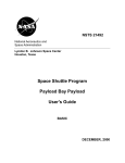
The PLDesign module USER MANUAL PLPAK Version 1.01 STRUCTURAL ANALYSIS SOFTWARE USING THE BOUNDARY ELEMENTS METHOD http://www.be4e.com E-mail: [email protected] 1 | PLPAK V1.01 User Manual ‐ PLDESIGN Table of Contents Disclaimer ............................................................................................................................................... 4 Copyright ................................................................................................................................................ 5 Introduction ............................................................................................................................................. 6 The PLDesign Operation Diagram ........................................................................................................... 6 The PLDesign philosophy ....................................................................................................................... 7 PLDesign capabilities: ............................................................................................................................. 8 The new interface should provide the user with the following capabilities: ............................................... 8 Starting the PLDesign.............................................................................................................................. 9 The PLDesign Menus ............................................................................................................................ 10 The File menu ................................................................................................................................... 10 File | Import LC ............................................................................................................................ 10 File | Open (.res) ........................................................................................................................... 10 File | Open (.des()) ........................................................................................................................ 10 File | Export Design Data .............................................................................................................. 10 File | Page setup ............................................................................................................................ 11 File | Print Preview........................................................................................................................ 11 File | Print ..................................................................................................................................... 11 The View Menu ................................................................................................................................ 12 View | Toolbar .............................................................................................................................. 12 View | Windows............................................................................................................................ 12 View | View Options ..................................................................................................................... 13 View | Fonts .................................................................................................................................. 13 View | Show/Hide Reactions ......................................................................................................... 13 View | Show/Hide Legend ............................................................................................................. 13 View | Show/Hide Assemblies....................................................................................................... 14 View | Show/Hide Slabs ................................................................................................................ 14 View | Show/Hide Slab RFT ......................................................................................................... 15 View | Show/Hide Beams .............................................................................................................. 15 View | Show/Hide Beams RFT ...................................................................................................... 16 View | Show/Hide Punching Critical Sections ............................................................................... 16 The Action menu ............................................................................................................................... 16 Action | Results Manager .............................................................................................................. 16 2 | PLPAK V1.01 User Manual ‐ PLDESIGN Action | Paths Manager ................................................................................................................. 22 Action | Select Case ...................................................................................................................... 22 Action | Assemblies....................................................................................................................... 22 Action | PL controls ...................................................................................................................... 23 Action | Beams .............................................................................................................................. 24 The Design menu .............................................................................................................................. 25 Design | Design model details ....................................................................................................... 25 Design | Design Slabs .................................................................................................................... 26 Design | Design Beams.................................................................................................................. 31 Design | Deflection Strips Manager ............................................................................................... 35 Design | Punching check ............................................................................................................... 35 The Detailing menu ........................................................................................................................... 36 Getting Help .......................................................................................................................................... 36 3 | PLPAK V1.01 User Manual ‐ PLDESIGN Disclaimer Considerable time, effort and expense have gone into the development and documentation of the PLPAKTM software. The PLPAKTM software has been thoroughly tested and used. The PLPAKTM software should be used by engineers with good understanding of concrete behavior, pre-stressing and structural mechanics. The user accepts and understands that no warranty is expressed or implied by the developers or the distributors on the accuracy or the reliability of the PLPAKTM software. The user must explicitly understand the assumptions of the PLPAKTM software and must independently verify the results produced by the PLPAKTM software. 4 | PLPAK V1.01 User Manual ‐ PLDESIGN Copyright Copyright © BE4E.com, 2000-2012 All rights reserved. The PLPAKTM, PLGenTM, PLViewTM, PLCoreMan TM, PLPostTM, PTPAKTM, PLTM, PL.EXETM, PLDesignTM are registered trademarks of BE4E.com. The computer program PLPAKTM and all associated documentation are proprietary and copyrighted products. Worldwide rights of ownership rest with BE4E.com. Unlicensed use of these programs or reproduction of documentation in any form, without prior written authorization from BE4E.com is explicitly prohibited. No part of this publication may be reproduced or distributed in any form or by any means, or stored in a database or retrieval system, without the prior explicit written permission of the BE4E.com. Further information and copies of this documentation may be obtained from: Phone: (732) 325-2616 Skype: youssef.f.rashed (technical director, Dr. Youssef F. Rashed) e-mail: [email protected] (for general questions) e-mail: [email protected] (for technical support questions) web: www.be4e.com 5 | PLPAK V1.01 User Manual ‐ PLDESIGN Introduction The PLDesign is an add-on for the PLPAK software (www.be4e.com) that is responsible for the automated reinforced concrete design of the slab and beam sections analyzed by the PLPAK. The PLDesign utilizes the BEM features adopted by the PLPLAK to offer to the user easy, fast and efficient design and detailing that suits any structural engineering community expectations. In this part of the manual, all the PLDesign commands and operations are going to be discussed explicitly. The PLDesign Operation Diagram $ALPHA$ Projectname.res Projectname.LC Projectname.basm Projectname.asm PLDesign.exe Projectname.SRFMT Projectname.BRFMT Calculation notes (.xls) Detailing (.dxf) $CDF$ $SDD$ $BDD$ $PROP$ $PUN$ PLSD.exe PLBD.exe MCALC.exe PUNCHK..exe $SDDR$ $BDDR$ $MCALC RES$ $PUNR$ PLDesign operation diagram 6 | PLPAK V1.01 User Manual ‐ PLDESIGN File Description Projectname.LC Load case file Projectname.res Results file Projectname.basm Beam assembly file $SDD$ Slab Design Data file $SDDR$ Slab Design Data Reinforcement file $BDD$ Beam Design Data file $BDDR$ Beam Design Data Reinforcement file $PROP$ Basic mesh Data file $MCALCRES$ Basic mesh maximum moment $PUN$ Punching Data file $PUNR$ Maximum punching stress file Projectname.SRFMT Slab reinforcement file Projectname.BRFMT Beam reinforcement file PLDesign file descriptions Program Description PLDesign.exe The main program that includes the user interface and controls the operation of other programs. PLSD.exe Slab designer PLBD.exe Beam designer Mcalc.exe Calculator of moment resistance of reinforcement mesh Punchk.exe Punching resistance calculator PLDesign programs description The PLDesign philosophy The PLDesign is the PLPAK component that will be responsible for the structural design of reinforced concrete slab and beam objects. The philosophy of the PLDesign is based on giving valued capabilities to the user. 7 | PLPAK V1.01 User Manual ‐ PLDESIGN PLDesign capabilities: The new interface should provide the user with the following capabilities: To utilize BEM results in the structural design easily. To choose the design code and appropriate design parameters. Currently, the PLDesign has the following codes: o The American Code (ACI), o The Eurocode (EC2). o Egyptian Code Of Practice (ECOP) To create full design for slab parts under bending moment based on either contour or strip results. To check punching stresses in the slab around regular/ irregular load/support elements. To create full design for beams under bending moment, shear and torsional stresses directly on the plan of the problem. To choose the reinforcement layout. To perform an accurate analysis for deflection limits. To export basic detailing. To export design results in the required formats to be used in RVT11ToPLGen. 8 | PLPAK V1.01 User Manual ‐ PLDESIGN Starting the PLDesign Step#1: Load the model from .LC file Step#2: Load the PLPost results already solved and saved as (*.res) (If necessary) 9 | PLPAK V1.01 User Manual ‐ PLDESIGN The PLDesign Menus The File menu File | Import LC Imports a numerical boundary element already completed and solved in the PLPost. This model will be used for the design purpose. File | Open (.res) Opens the results already saved by the user in the PLPost (either global or local contours, strips or other results) already solved. File | Open (.des ()) Opens a design result already saved in the PLDesign. File | Export Design Data This window is used to export the PLDesign design data to Excel & Revit for detailing. In this window you can define the required slabs and beams for export. The host level in Revit files can be imported in Revit using the Load Reinforcement from PLDesign tool. The tab gives the user a great advantage to export the model already designed to AutoDesk Revit to preview the required detailing for each section. 10 | PLPAK V1.01 User Manual ‐ PLDESIGN File | Page setup Brings up a dialog box in which the user can choose the size of the paper, the orientation and the margins File | Print Preview Brings up a small window in which the user can preview the .des file before printing File | Print Brings up a dialog box in which the user can choose the printer and print the current .des file 11 | PLPAK V1.01 User Manual ‐ PLDESIGN The View Menu View | Toolbar Used to control which toolbars should appear on the screen, the same function can be performed using right click on any toolbar. The mark beside a toolbar implies that it is selected. View | Windows Used to choose window options while using more than a single PLDesign interface at the same time. 12 | PLPAK V1.01 User Manual ‐ PLDESIGN View | View Options Clicking on view options allow you to change the drawing sequence of the result elements, grid spacing, element thickness, opacity & colors of different elements. Use this list to edit the drawing mode Use these lists to edit the grid spacing and element thickness Use this scroll bar to edit the column and beam transperency Use these buttons to delete defined material Use this button to restore default settings Use this button to save settings View | Fonts View | Show/Hide Reactions The Show/Hide commands can be used to show or hide Loads, No. of divisions of every element, Coordinates of the cursor, grid and axis View | Show/Hide Legend The Show/Hide legend command is used to view the legend corresponding to the contours displayed by the user. 13 | PLPAK V1.01 User Manual ‐ PLDESIGN View | Show/Hide Assemblies The Show/Hide command is used to show the Straining actions of Assemblies (Shear walls without beams, Columns loads without beams). View | Show/Hide Slabs Used to preview a numbering for each rectangular or quadrilateral contour used for the slabs design. 14 | PLPAK V1.01 User Manual ‐ PLDESIGN View | Show/Hide Slab RFT Used to preview the reinforcement required for each design slab in both major and minor directions. View | Show/Hide Beams The Show/Hide Beam Command allows the user to recognize each beam name necessary for the design. 15 | PLPAK V1.01 User Manual ‐ PLDESIGN View | Show/Hide Beams RFT The Show/Hide Beams RFT command allows the user to be acquainted with the beams components such as sections and breaks which are set by the user as shown later. Hint about Sections and Breaks of the beams: Each beam is divided into three regions defined by four breaks surrounding them (Start Break, End Break, Break 3, Break 4).The most critical section in each region is chosen relative to the region’s length (0.5 of the middle region, and 0.1 starting from the ends of the left and right region). Section A Break 1 Section B Section C Break 2 Break 3 Section D Section E Break 4 View | Show/Hide Punching Critical Sections The Show/Hide Punching critical section command shows/hides punching critical sections. The Action menu Action | Results Manager This command shows the results manager which is used to control the properties of the strips and result areas which have been previously drawn. 16 | PLPAK V1.01 User Manual ‐ PLDESIGN Beam 17 | PLPAK V1.01 User Manual ‐ PLDESIGN PLPost Results The following table shows the results that can be shown by PLPost. Quantity Description Rx Rotation about the X axis Ry Rotation about the Y axis Uz Deflection in Z axis direction Mxx Bendng moment in X direction Mxy Twisting moments about X and Y directions Myy Bendng moment in Y direction Qx Shear Force in X direction Qy Shear Force in Y direction Mii Bendng moment in i direction Mij Twisting moments about i and j directions Mjj Bendng moment in j direction Qi Shear Force in i direction Qj Shear Force in j direction Mmax Maximum principal bending moment Mmin Minimum principal bending moment Mxxdes Design moment in X direction Myydes Design moment in Y direction Miides Design moment in i direction Mjjdes Design moment in j direction 18 | PLPAK V1.01 User Manual ‐ PLDESIGN Strips: Use this button to delete the strip Use this box to edit the strip name Use this box to define no. of points to be solved Use this button to export the result file List box containing names of strips Use this list to choose which straining action should be displayed Use this box to define start point of strip Choose whether the strip should be solved or not Checking this box shows the result Use the scroll bar to control size of graphs produced Define the angle at which results should be shown. You can view results on prinicipal axis Use this box to define end point of strip Strips: This part of results manager is used to control strip properties including ID, Start and End points, No. of points within the strip, type of stress resultant that is required to be displayed at this strip. Export command is used to export a tabulated format of the strip results, the produced tables can be used by any spreadsheet software. Contours: This part of the Results Manager is used to control properties of the contour areas. Main Contour is used to display contours all over the model, this is the only contour that can not be deleted. Using this dialogue 19 | PLPAK V1.01 User Manual ‐ PLDESIGN you can control Contour ID, Type of stress component to be displayed, N which is the number of colours within the contour, spacing between points to be solved within the contour. Export command is used to export a tabulated format of the strip results, the produced tables can be used by any spreadsheet software. Use this button to delete the strip Use this box to edit the contour name Use this box to define no. of points to be solved List box containing names of strips Use this button to export the result file Checking this box allows user to define minimum value for contours Checking this box allows user to define maximum value for contours Checking this box shows the result Use this box to define spacing between points to be solved Used to define angle at which results should be displayed Used to define straining action required o be displayed 20 | PLPAK V1.01 User Manual ‐ PLDESIGN Define maximum value to be shown by the contour Define minimum value to be shown by the contour Column Plot: This part of result manager is used to show contour results at supports. This part is used to control the number of contour colours and type of stress component to be displayed. Export command is used to export a tabulated format of the strip results, the produced tables can be used by any spreadsheet software. 21 | PLPAK V1.01 User Manual ‐ PLDESIGN Action | Paths Manager Action | Select Case This command is used to select the load cases or combos that are required for the design of the slabs and the beams. We can also enter Envelop between the load cases and the combos. Action | Assemblies This command is used to show the cell properties. In order to show assembly results, type the cell number in the lower left box, then click add. The assembly results can be read at the normal X and Y directions or at any direction. The results at principal directions can be shown using the command “use principal”. The results can be exported to a file with a format that can be opened using any spreadsheet software. 22 | PLPAK V1.01 User Manual ‐ PLDESIGN Add assembly Delete assembly Display assembly name Display assembly area Export result file for assembly When checked, allows the user to define CG manually List box containing names of support assemblies Sets “theta” to equal angle of principal direction List box containing numbers of support assemblies Displays straining actions and inertias in the “theta” direction List box containing names of load assemblies List box containing numbers of load assemblies Action | PL controls Refer to PLCoreMan manual. 23 | PLPAK V1.01 User Manual ‐ PLDESIGN Displays straining actions and inertias Export all result file for assembly load supports & load cells Load assemblies file (.asm) Click to close and save settings Action | Beams This command is used to display and edit beam results. The produced dialogue is used to show beam nodes, directions, and type of stress component that should be displayed on the beam. Checkbox group controlling what is the beam that the user wants to show Checkbox group controlling what to be displayed Exports result file for assembly Scrollbar which controls size of results on screen 24 | PLPAK V1.01 User Manual ‐ PLDESIGN Used to choose straining action to be displayed Click to close and save settings The Design menu Design | Design model details Design codes zone Model units zone Design materials zone 25 | PLPAK V1.01 User Manual ‐ PLDESIGN The design codes allow the user to choose the required design code and to change the relevant design parameters. Currently, PLDesign supports ACI, EC2 and ECP. Throughout the PLPAK components, all the models were unit less; i.e., the user had to keep his units consistent. In PLDesign, the model units have to be defined; therefore, the model unit zone can be used by the user to define the models that he has been using so far throughout the model. The design materials zone allows the user to create and define the properties of any number of required design materials. The design materials are then attached to design slabs or beam sections. Design | Design Slabs This is the PLDesign menu that can be used to design slab parts under flexural stresses. When you choose to “Add strip to main model” a design slab, this dialogue box will allow you to create design slabs from ready local contours or strip results (present in the Results Manager). 26 | PLPAK V1.01 User Manual ‐ PLDESIGN If you choose to create design slabs from contours, you will reach this mean that can be used to create multiple design slabs from local contours. If you choose to create design slabs from strips, you will reach this menu that can be used to create design slabs from strips. The definition of a design slab from a strip requires the user to define the main strip and the area definition strips. 27 | PLPAK V1.01 User Manual ‐ PLDESIGN After creating your design slabs you can edit them directly from the Edit Design Slab menu shown below. This menu can be used to modify all possible slab design properties, reinforcement layout. In addition, it will display design errors if any. 28 | PLPAK V1.01 User Manual ‐ PLDESIGN Slabs: Match Properties The match properties command is used to match a slab (Source Slab) to other slabs (Destination Slab) having the same properties as the source one. Make sure that the bordered boxes are toggled ‘off’; else wise the reinforcement of the first slab (Source Slab) will be similar to the Destination slabs. 29 | PLPAK V1.01 User Manual ‐ PLDESIGN Press on “Start slab design” to start showing the as required for each design slab in both X and Y directions. Choose the Bar Diameter, the corresponding minimum number of rebar will show up, thus input the integer number of required rebar. 30 | PLPAK V1.01 User Manual ‐ PLDESIGN Design | Design Beams The following is the main design beams window. When opening this window, the beams have to be loaded from the Read Beam Data button. This button will ask the user to read the beam assembly file (.basm) that should have been previously exported from the PLGen. Press "Read Beam Data" Open (.basm) After loading the beams, the beam breaks and design sections positions can be defined using the “Define design regions” button. This menu allows the user to define and/or modify break and section positions using their relative or absolute position simultaneously. 31 | PLPAK V1.01 User Manual ‐ PLDESIGN Defining the Sections and Preparing for reinforcement Clicking on “Define reinforcement details” will take the user to the following menu that can be used to define design load cases for each section straining action. The menu functions as a reinforcement builder that can be used to define section reinforcement layers, stirrups and longitudinal bars. In addition, it calculates the reinforcement amount built and compares it to the required area of steel and informs the user whether the section is safe or not. The reinforcement of a beam section is defined by three distinct types of reinforcement: Reinforcement Layers for top and bottom steel to withstand flexure in beams. Stirrups to withstand shear and torsion in beams. Longitudinal reinforcement to withstand torsion in beams or any other purpose. 32 | PLPAK V1.01 User Manual ‐ PLDESIGN Beams: Match Properties 33 | PLPAK V1.01 User Manual ‐ PLDESIGN Similar beams are matched with the same reinforcement The users can also match properties for the sections in one beam Similar beam sections are matched with the same reinforcement 34 | PLPAK V1.01 User Manual ‐ PLDESIGN Design | Deflection Strips Manager It shows the Maximum deflection (according to selected moment) & the effective length of any selected strip. Design | Punching check The variables defines in the critical section properties window are similar to punching critical section properties as stated by ACI-318. These variables are: a,b: critical section dimensions Beta: ratio between b and a b1: dimension of the critical section in the direction of the analysis b2: dimension of the critical section in the direction perpendicular to b1 Bo: perimeter of the critical section d: depth of the slab at this point 35 | PLPAK V1.01 User Manual ‐ PLDESIGN Alpha: Constant defined based on the position of the column The Detailing menu PLDesign can be used to export design drawings for the designed beams and slabs. The drawings are exported in (.dxf) format. The PLDesign allows the user to choose the drawing components, layers and their respective colors. Getting Help The BE4E.com customer support team is always welcoming problems and suggestions of registered customers. Just send an e-mail including your questions, or your model together with your questions to:[email protected] Also check our site news at www.be4e.com regularly for Problems and Solutions section and the Frequently Asked Questions section. 36 | PLPAK V1.01 User Manual ‐ PLDESIGN