1
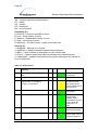
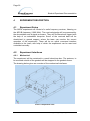
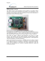
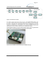
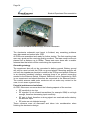
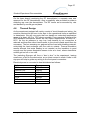
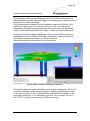
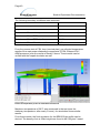
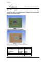
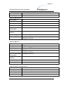
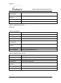
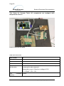
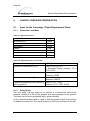
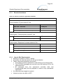
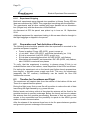
Page 29
Student Experiment Documentation
4.3
Experiment Components
Table 4-1: Experiment summary table
Experiment mass (in kg):
2
Experiment dimensions (in m):
0,2x0,2x0,1
2
Experiment footprint area (in m ):
0,04
3
Experiment volume (in m ):
0,004
Experiment expected COG (centre of near the base of the
gravity) position:
box, in the middle of the footprint area
The information in the table lists the dimensions of the E-Box. For mounting
purposes, the experiment spans two L-profiles between the gondola rails.
Antenna Dimensions:
Antenna mass (in kg)
Antenna length (in m)
Antenna diameter (in m)
Antenna COG:
4.4
<0,5
1
< 0,05
In the middle
Mechanical Design
As the experiment consists mostly of electronic components (circuit boards),
the design will be quite small. It will be housed in an aluminium box and will
be fastened to the gondola via the provided mounting brackets. The drawing
in Chapter 4.2.1 shows mechanical dimensions of the experiment box, as
seen from the outside. The experiment box mainly consists of two bent
aluminium sheets and multiple L sections, which are screwed together and
attached to the experiments mounting rails. To ensure easy access to the
experiment setup, the top is made of a separate aluminium sheet.
To protect the electronics inside the box against temperature influence, the
experiment will be using anti-static Styropor parts cut in shape to insulate the
box and to support any cabling to the front panel. The PCBs are fixed by bolts
to the base of the box, which are guided through the Styropor. This mounting
technique is very weight-efficient and guards efficiently against shock and
temperature transients, as Styropor has high thermal resistance.
BX18_ARCA_SED_v5-0_12JAN15.docx